

Page 1

Installation and maintenance manual
Notice d’installation et de maintenance
Installations und Wartungshandbuch
Manuale di installazione e di manutanzione
Manual de instalacion y de mantenimiento
IOM TRIO 01-EL-1ALL
Part number / Code / Code / Codice / Código : 3990216
Supersedes / Annule et remplace / annulliert und ersezt /
Annulla e sostituisce / anula y sustituye : None / Néant / Nichht / Nulla / Ninguno
WMT 090914 RC
HIGH TECH
MULTISPLITS
SIMULTANEOUS COOLING - HEATING
FROID – CHAUD SIMULTANE
GLEICHZEITIGER HEIZ UND KÜHLBETRIEB
FREDDO – CALDO SIMULTANEI
FRÍO – CALOR SIMULTÁNEO
7.5 0kW
7.06kW
WMN9 - WMN12
WMZ9 - WMZ12
PXD9 - PXD12
ECF9 - ECF11
WMF9 - WMF12
LS11
Page 2

Page 3

INSTINST
INSTINST
INST
ALLAALLA
ALLAALLA
ALLA
TION INSTRUCTIONSTION INSTRUCTIONS
TION INSTRUCTIONSTION INSTRUCTIONS
TION INSTRUCTIONS
NOTICE D’INSTALLATION
INSTALLATIONSHANDBUCH
ISTRUZIONI INST ALLAZIONE
INSTRUCCIONES DE INSTALACIÓN
Page 4

22
22
2
CONTENTSCONTENTS
CONTENTSCONTENTS
CONTENTS
GENERAL RECOMMENDGENERAL RECOMMEND
GENERAL RECOMMENDGENERAL RECOMMEND
GENERAL RECOMMEND
AA
AA
A
TIONSTIONS
TIONSTIONS
TIONS
..............................................................................................................................................................................................................
..............................................................................................................................................................................................................
.......................................................................................................
33
33
3
SAFETY AD VICE...................................................................................................................................3
WARNING .........................................................................................................................................3
PP
PP
P
AA
AA
A
CKACKA
CKACKA
CKA
GE CONTENTSGE CONTENTS
GE CONTENTSGE CONTENTS
GE CONTENTS
..............................................................................................................................................................................................................................................
..............................................................................................................................................................................................................................................
.......................................................................................................................
44
44
4
ACCESSORIESACCESSORIES
ACCESSORIESACCESSORIES
ACCESSORIES
........................................................................................................................................................................................................................................................................
........................................................................................................................................................................................................................................................................
....................................................................................................................................
44
44
4
GENERALGENERAL
GENERALGENERAL
GENERAL
......................................................................................................................................................................................................................................................................................
......................................................................................................................................................................................................................................................................................
...........................................................................................................................................
44
44
4
CHARACTERISTICS...............................................................................................................................4
CONFIGURATION POSSIBILITIES ..........................................................................................................5
OUTDOO RS UNIT – DESCRI PTION.......................................................................................................6
DIMENSIONSDIMENSIONS
DIMENSIONSDIMENSIONS
DIMENSIONS
..........................................................................................................................................................................................................................................................................
..........................................................................................................................................................................................................................................................................
.....................................................................................................................................
77
77
7
HANDLING PROCEDUREHANDLING PROCEDURE
HANDLING PROCEDUREHANDLING PROCEDURE
HANDLING PROCEDURE
....................................................................................................................................................................................................................................
....................................................................................................................................................................................................................................
..................................................................................................................
88
88
8
TECHNICAL SPECIFICATECHNICAL SPECIFICA
TECHNICAL SPECIFICATECHNICAL SPECIFICA
TECHNICAL SPECIFICA
TIONSTIONS
TIONSTIONS
TIONS
......................................................................................................................................................................................................................
......................................................................................................................................................................................................................
...........................................................................................................
88
88
8
ELECTRICAL SPECIFICAELECTRICAL SPECIFICA
ELECTRICAL SPECIFICAELECTRICAL SPECIFICA
ELECTRICAL SPECIFICA
TIONSTIONS
TIONSTIONS
TIONS
......................................................................................................................................................................................................................
......................................................................................................................................................................................................................
...........................................................................................................
99
99
9
REFRIGERAREFRIGERA
REFRIGERAREFRIGERA
REFRIGERA
TING SPECIFICATING SPECIFICA
TING SPECIFICATING SPECIFICA
TING SPECIFICA
TIONSTIONS
TIONSTIONS
TIONS
..................................................................................................................................................................................................
..................................................................................................................................................................................................
.................................................................................................
1010
1010
10
WMT 090914 RC INSTWMT 090914 RC INST
WMT 090914 RC INSTWMT 090914 RC INST
WMT 090914 RC INST
ALLAALLA
ALLAALLA
ALLA
TIONTION
TIONTION
TION
..........................................................................................................................................................................................................
..........................................................................................................................................................................................................
.....................................................................................................
1111
1111
11
GROUND AGROUND A
GROUND AGROUND A
GROUND A
TTTT
TTTT
TT
AA
AA
A
CHMENTCHMENT
CHMENTCHMENT
CHMENT
..................................................................................................................................................................................................................................
..................................................................................................................................................................................................................................
.................................................................................................................
1111
1111
11
CONDENSACONDENSA
CONDENSACONDENSA
CONDENSA
TE EVTE EV
TE EVTE EV
TE EV
AA
AA
A
CUCU
CUCU
CU
AA
AA
A
TION – DRAIN POSITIONINGTION – DRAIN POSITIONING
TION – DRAIN POSITIONINGTION – DRAIN POSITIONING
TION – DRAIN POSITIONING
....................................................................................................................................
....................................................................................................................................
..................................................................
1111
1111
11
DISTDIST
DISTDIST
DIST
ANCES AND LEVEL DIFFERENCES BETWEEN ST AND WMT 090914 RCANCES AND LEVEL DIFFERENCES BETWEEN ST AND WMT 090914 RC
ANCES AND LEVEL DIFFERENCES BETWEEN ST AND WMT 090914 RCANCES AND LEVEL DIFFERENCES BETWEEN ST AND WMT 090914 RC
ANCES AND LEVEL DIFFERENCES BETWEEN ST AND WMT 090914 RC
................................................................
................................................................
................................
1212
1212
12
PIPE CONNECTIONSPIPE CONNECTIONS
PIPE CONNECTIONSPIPE CONNECTIONS
PIPE CONNECTIONS
..............................................................................................................................................................................................................................................
..............................................................................................................................................................................................................................................
.......................................................................................................................
1313
1313
13
REFRIGERATION PIPE CONNECTIONS BETWEEN WMT 090914 RC AND ST..........................................13
PIPE WORK TO BE PRODUCED ON SITE............................................................................................. 1 3
REFRIGERATING PIPE CONNECTIONSLIAISONS FRIGORIFIQUES.........................................................13
REFRIGERATING PIPE CONNECTIONS BETWEEN THE INDOORS UNITS AND THE OUTDOORS UNIT ..... 1 4
EXAMPLE OF CONNECTION REQUIRING ADDITION OF R407C REFRIGERANT .................................... 15
VV
VV
V
AA
AA
A
CUUM DRAINING THE INDOORS UNIT AND THE REFRIGERACUUM DRAINING THE INDOORS UNIT AND THE REFRIGERA
CUUM DRAINING THE INDOORS UNIT AND THE REFRIGERACUUM DRAINING THE INDOORS UNIT AND THE REFRIGERA
CUUM DRAINING THE INDOORS UNIT AND THE REFRIGERA
TING PIPESTING PIPES
TING PIPESTING PIPES
TING PIPES
............................................................
............................................................
..............................
1616
1616
16
VACUUM DRAINING PROCEDURE.....................................................................................................16
WIRING DIAGRAM AND LEGENDWIRING DIAGRAM AND LEGEND
WIRING DIAGRAM AND LEGENDWIRING DIAGRAM AND LEGEND
WIRING DIAGRAM AND LEGEND
....................................................................................................................................................................................................
....................................................................................................................................................................................................
..................................................................................................
1717
1717
17
ELECTRICAL CONNECTIONSELECTRICAL CONNECTIONS
ELECTRICAL CONNECTIONSELECTRICAL CONNECTIONS
ELECTRICAL CONNECTIONS
....................................................................................................................................................................................................................
....................................................................................................................................................................................................................
..........................................................................................................
1919
1919
19
INDO ORS U NITS:..............................................................................................................................19
OUT DOOR S UNI T : ............................................................................................................................ 19
INDOORS UNITS INSTINDOORS UNITS INST
INDOORS UNITS INSTINDOORS UNITS INST
INDOORS UNITS INST
ALLAALLA
ALLAALLA
ALLA
TIONTION
TIONTION
TION
..........................................................................................................................................................................................................
..........................................................................................................................................................................................................
.....................................................................................................
2020
2020
20
SCHEMATIC DIAGRAM - WMT 090914 RC WITH ST AND WITHOUT ELECTRICAL HEA TING.....................21
SCHEMATIC DIAGRAM - WMT 090914 RC WITH ST - WITH ELECTRICAL HEA TING ..................................22
FUSE HOLDE R CONNECTIO N DET AILS ON MODEL WITH E LECTRICAL H EAT ING................................... 2 3
REGULAREGULA
REGULAREGULA
REGULA
TION SYSTEMTION SYSTEM
TION SYSTEMTION SYSTEM
TION SYSTEM
............................................................................................................................................................................................................................................
............................................................................................................................................................................................................................................
......................................................................................................................
2424
2424
24
GENERAL OPERATING PRINCIPLES.....................................................................................................24
SAFET Y PRO TEC TION........................................................................................................................ 24
DE-ICING......................................................................................................................................... 24
CHECKS BEFORE STCHECKS BEFORE ST
CHECKS BEFORE STCHECKS BEFORE ST
CHECKS BEFORE ST
ARAR
ARAR
AR
TINGTING
TINGTING
TING
........................................................................................................................................................................................................................
........................................................................................................................................................................................................................
............................................................................................................
2525
2525
25
POWER SUPPLY.................................................................................................................................25
ELECT RICAL T UBING ......................................................................................................................... 25
CONDENSA T ES DRAINA GE ............................................................................................................... 25
REFRIGE RANT CON NECTIONS.......................................................................................................... 25
CONNECT IONS THR OUGH A WA LL................................................................................................... 25
ATTACHMENT...................................................................................................................................25
FINAL TFINAL T
FINAL TFINAL T
FINAL T
ASKSASKS
ASKSASKS
ASKS
..........................................................................................................................................................................................................................................................................
..........................................................................................................................................................................................................................................................................
.....................................................................................................................................
2525
2525
25
MAINTENANCE AND SERVICINGMAINTENANCE AND SERVICING
MAINTENANCE AND SERVICINGMAINTENANCE AND SERVICING
MAINTENANCE AND SERVICING
......................................................................................................................................................................................................
......................................................................................................................................................................................................
...................................................................................................
2626
2626
26
Page 5
33
33
3
WMTWMT
WMTWMT
WMT
090914 RC090914 RC
090914 RC090914 RC
090914 RC
High THigh T
High THigh T
High T
echech
echech
ech
POWER SUPPLPOWER SUPPL
POWER SUPPLPOWER SUPPL
POWER SUPPL
Y MUST BEY MUST BE
Y MUST BEY MUST BE
Y MUST BE
CUT OFF BEFORECUT OFF BEFORE
CUT OFF BEFORECUT OFF BEFORE
CUT OFF BEFORE
STST
STST
ST
ARAR
ARAR
AR
TING ANY WORK ONTING ANY WORK ON
TING ANY WORK ONTING ANY WORK ON
TING ANY WORK ON
THE ELECTRICAL BOTHE ELECTRICAL BO
THE ELECTRICAL BOTHE ELECTRICAL BO
THE ELECTRICAL BO
XESXES
XESXES
XES
GENERAL RECOMMENDGENERAL RECOMMEND
GENERAL RECOMMENDGENERAL RECOMMEND
GENERAL RECOMMEND
AA
AA
A
TIONSTIONS
TIONSTIONS
TIONS
Firstly, congratulations for having selected an air conditioner.
SAFETY ADVICE
Always follow current safety regulations when working on your equipment.
Only qualified personnel should perform equipment installation and maintenance.
Make sure that the electrical voltage and frequency are adapted to the required operating
power supply, taking account of the specific installation conditions and the power required by
any other appliance connected on the same circuit.
WARNING
The power supply must be cut off before starting any work or maintenance operation.
The manufacturer declines all liability, and the guarantee becomes void, in the event of non-
compliance with these installation instructions.
In case of difficulties, please contact your local Technical Department.
If possible, assemble the mandatory or optional accessories before placing the appliance on
its final location (refer to the instructions provided with each accessory).
The information contained in these instructions is subject to change without prior notice.The information contained in these instructions is subject to change without prior notice.
The information contained in these instructions is subject to change without prior notice.The information contained in these instructions is subject to change without prior notice.
The information contained in these instructions is subject to change without prior notice.
This appliance complies with
EC STEC ST
EC STEC ST
EC ST
ANDAND
ANDAND
AND
ARDSARDS
ARDSARDS
ARDS
..
..
.
Page 6
44
44
4
WMTWMT
WMTWMT
WMT
090914 RC090914 RC
090914 RC090914 RC
090914 RC
High THigh T
High THigh T
High T
echech
echech
ech
GENERALGENERAL
GENERALGENERAL
GENERAL
CHARACTERISTICS
The outdoors reversible unit (WMT 090914 RC) comprises:
2 independent refrigerating circuits
1 unit per circuit A and 2 unitS per circuit B
Rotary compressor
Microprocessor control
It is compatible with Comfort range indoors units
PP
PP
P
AA
AA
A
CKACKA
CKACKA
CKA
GE CONTENTSGE CONTENTS
GE CONTENTSGE CONTENTS
GE CONTENTS
1 WMT 090914 RC outdoors unit
4 rubber pads
1 bag of fasteners
1 shunts (model with electrical heating)
10 cable ties
1 drain + seal
3 connectors
1 identification label for the wiring and pipe connections between the indoors unit and the
WMT 090914 RC
1 bag of documentation
AA
AA
A
CCESSORIESCCESSORIES
CCESSORIESCCESSORIES
CCESSORIES
Wall bracket
1/2"-1/4" Flare connectors
3/8"-1/4" Flare connectors
Page 7
55
55
5
WMTWMT
WMTWMT
WMT
090914 RC090914 RC
090914 RC090914 RC
090914 RC
High THigh T
High THigh T
High T
echech
echech
ech
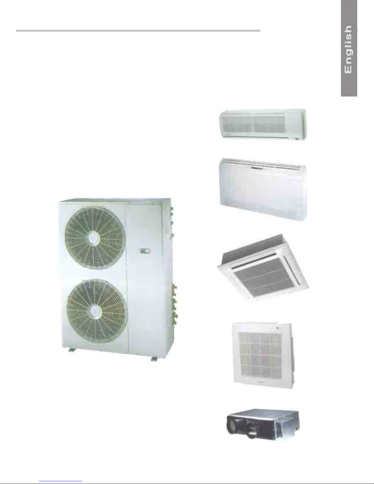
CONFIGURATION POSSIBILITIES
The difference in capacities between the two circuits added to the broad variety of installation
configurations mean that «Made to measure» air conditioning installations, perfectly adapted
to each application, can be created.
WMN9 - WMN 12
WMZ9 - WMZ12
PXD9 - PXD12
ECF9 - ECF11
WMF9 - WMF 12
LS11
Page 8
66
66
6
WMTWMT
WMTWMT
WMT
090914 RC090914 RC
090914 RC090914 RC
090914 RC
High THigh T
High THigh T
High T
echech
echech
ech
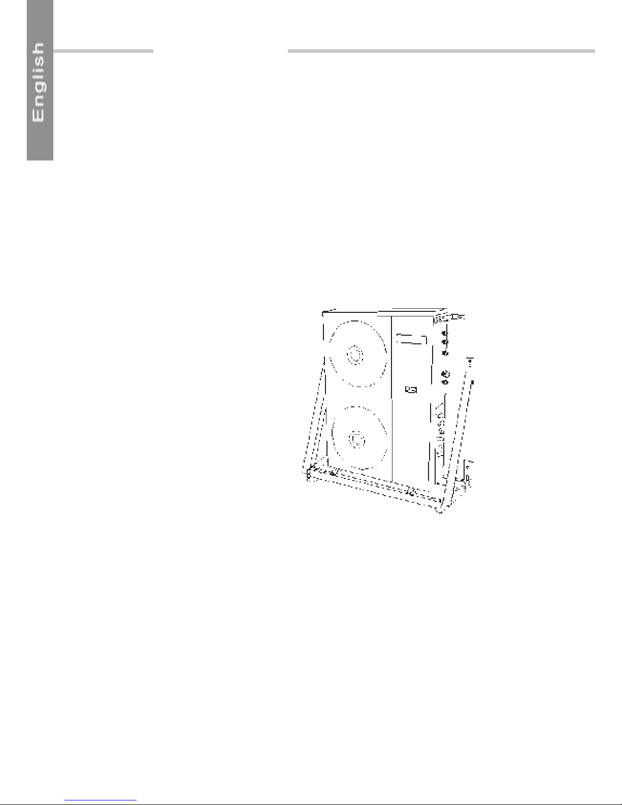
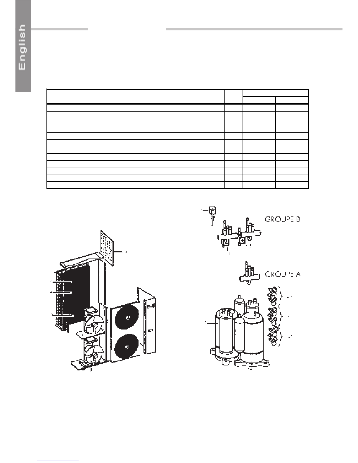
OUTDOORS UNIT – DESCRIPTION
One of the WMT 090914 RC HIGH TECH’s advantages is its compact design, taking up
very little floor space. Each circuit comprises:
REP.
AB
Rotary compressor 1 1 1
Ax i al fan (dual speed) 2 1 1
Main ex changer 3 1 1
Aux i l iary ex c hanger for optim ising operat ion under parti al l oad condit i ons 4 1
3/8’’ s ol enoid valves for cont roll i ng t he following m odes : 5 2
Eac h S T unit’ s Unoccupied or Standby m ode
One ¼’’ solenoid valve for discharging refrigerant into the auxiliary exchang 6 1
A s i ngle S T in operati on
4 way valves for thermodynami c heat ing 7 1 2
Temperature sensors
OAT (Outdoors A ir Temperature) 1 1
OCT (Out doors Coil Temperature) 1 2
DESCRIPTION UNIT
A regulator in the electrical box automatically manages the functions of the entire installation
in accordance with the demands expressed by the indoors units.(8)
Page 9
77
77
7
WMTWMT
WMTWMT
WMT
090914 RC090914 RC
090914 RC090914 RC
090914 RC
High THigh T
High THigh T
High T
echech
echech
ech
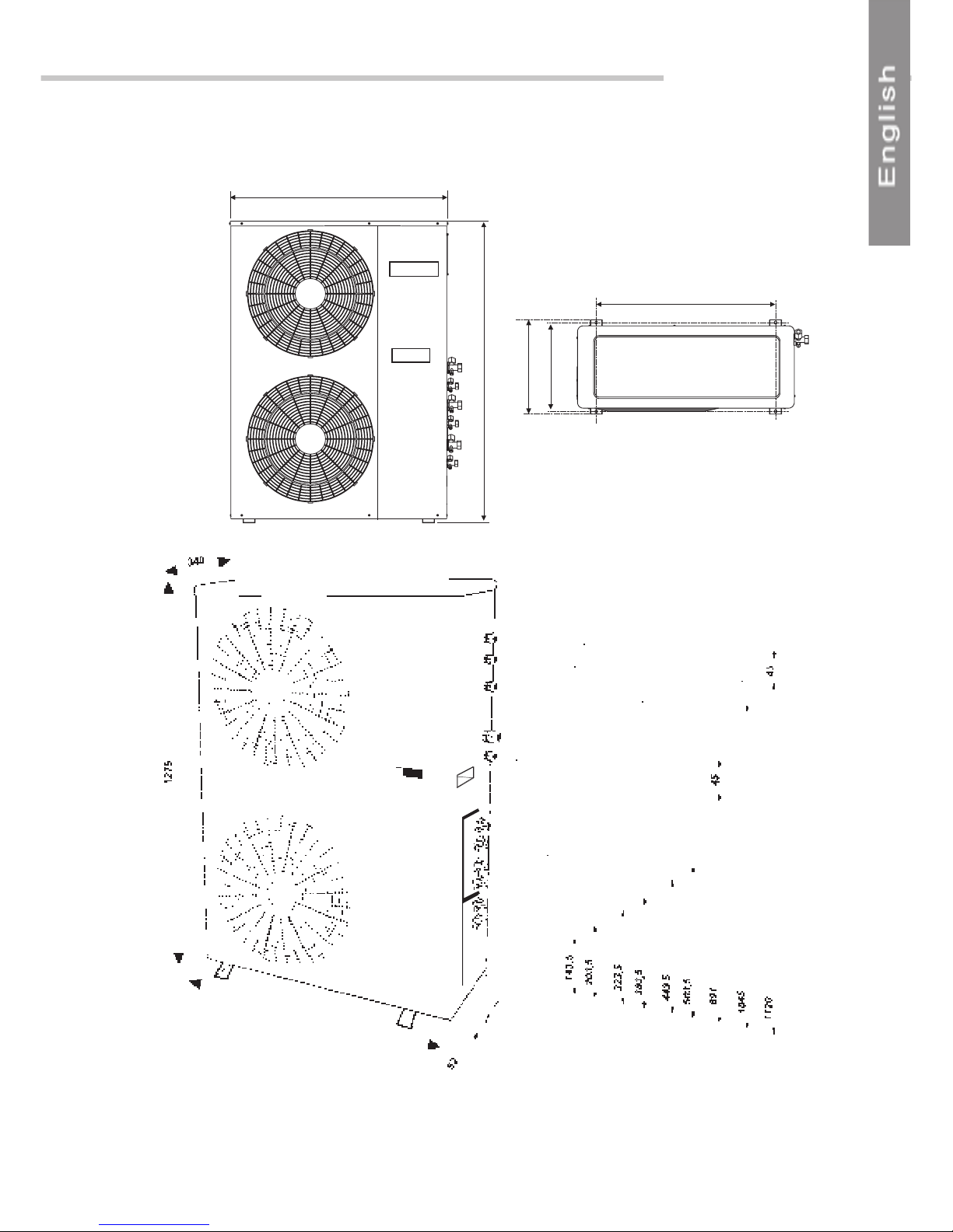
902
1275
DIMENSIONSDIMENSIONS
DIMENSIONSDIMENSIONS
DIMENSIONS
**
**
*
2 packing boxes for the mains power supply.
2 different sizes: installer to choose size in relation to mains power supply cable section (ST
with or without electrical heating).
*
CIRCUIT ACIRCUIT A
CIRCUIT ACIRCUIT A
CIRCUIT A
GAS
LIQUID
GAS
LIQUID
CIRCUIT BCIRCUIT B
CIRCUIT BCIRCUIT B
CIRCUIT B
GAS
LIQUID
902 Without valves
952 · With valves
Dimensions in relation to ground
705
357
380
Page 10

88
88
8
WMTWMT
WMTWMT
WMT
090914 RC090914 RC
090914 RC090914 RC
090914 RC
High THigh T
High THigh T
High T
echech
echech
ech
TECHNICAL SPECIFICATECHNICAL SPECIFICA
TECHNICAL SPECIFICATECHNICAL SPECIFICA
TECHNICAL SPECIFICA
TIONSTIONS
TIONSTIONS
TIONS
R407C
HE
A
T PUMP
Refrigerant char g e (*) g
757
Connecting pipe
s
Gas pipe
in (") - mm ½” - 12
Liquid pi pe
in(") - mm 1/4" - 6
Refrigerant char g e (*)
1315
Connecting pipe
s
Gas pipe
in(") - mm
3/8” - 10
Liquid pi pe
in(") - mm 1/4" - 6
Upper limit °C
43°C DB
Lower limit °C
21°C DB
Upper limit °C
24°C DB / 18°C WB
Lower limit °C
-5°C DB / -6°C WB
CIRCUIT B
CIRCUIT A
Model
Unit operating range
Cooling mode operating ran ge
Heating mode operating range
HANDLING PROCEDUREHANDLING PROCEDURE
HANDLING PROCEDUREHANDLING PROCEDURE
HANDLING PROCEDURE
Centre of gravity
113 kg Net weight
124 Kg Packed weight
* The R407C refrigerant charge value is given for 4 m pipe length connections with WMN
type outdoors units on both circuits
For any installations with longer pipe lengths, please refer to: § REFRIGERATING
SPECIFICATIONS and Example of connection requiring addition of R407c refrigerant
(DB)(DB)
(DB)(DB)
(DB) Dry Bulb temperature
(WB)(WB)
(WB)(WB)
(WB) Wet bulb temperature
Page 11

99
99
9
WMTWMT
WMTWMT
WMT
090914 RC090914 RC
090914 RC090914 RC
090914 RC
High THigh T
High THigh T
High T
echech
echech
ech
ELECTRICAL SPECIFICAELECTRICAL SPECIFICA
ELECTRICAL SPECIFICAELECTRICAL SPECIFICA
ELECTRICAL SPECIFICA
TIONSTIONS
TIONSTIONS
TIONS
TRIO HEAT PUMP
ABCD
Number of ST units without heating 3
3
2 1 0
Number of ST units with heating 0
0
1 2 3
Unité
Total nominal current A 12.2 20.7 27.3 33.9
Total maxi mum curre nt A 15 23.5 30.1 36.7
Total s tarting curre nt A 70 78.5 85.1 91.7
Fuse ra ting aM/VD E A 20/20 25/25 32/35 40/50
3G type power supply cable section mm² 2,5 6 10 10
CONFIG URATION EXA M PLE Unité A B C D
Ma x . curren t / ST w/o elec. h ea ting A 1 X 1,5 0 0 0
Ma x c urrent / ST wit h elec. heat in g (U NI T A) A ¬0 1 X 10,2 1 X 10,2 1 X 10,2
Max. current / ST w/o elec. heating A 2 X 1,5 2 X 1,5¬¬1 X 1,5¬ 0
Ma x current / ST wi t h el ec. hea t in g (U NI T B ) A 0 0 1 X 6,6 2 X 6,6
Fus e r ati ng with electric a l h ea ting aM A 0 10 10 /10 10 / 20
6G type ST connecting cable section mm² 1,5 1,5 1,5 1,5
UNIT A: FUSE QF1
UNIT B: FUSE QF23
ELECTRICAL CONNECTIONS TO ST UNITS
Indoors unit type Electrical heating capacity
(W)
Maximu m c u rr ent
(A)
PXD 9 1250 6,6
ECF 9 900 4,7
LS 11 1600 8, 5
PXD 12 1250 6,6
ECF 11 900 4,7
IMPORIMPOR
IMPORIMPOR
IMPOR
TT
TT
T
ANTANT
ANTANT
ANT
* The installer must comply with all local standards. The cable section must be suitable for the
installation method, the type of cable insulation and the cable length.
These values are provided for information purposes only. They must be verified and adapted
in relation to existing standards.
These values may vary in relation to the type of installation and the choice of conductors.
Comments:
This data is given for the most unfavourable installation in terms of maximum current
draw: 1 LS11 on circuit A / 2 PXD9 on circuit B
Case with 3 cassettes (2 x ECF9 + 2 x ECF11):
8A fuse is to be provided for unit A
16A fuse is to be provided for unit B .
Electrical heating details for each ST for determining the appropriate fuse rating
Page 12

1010
1010
10
WMTWMT
WMTWMT
WMT
090914 RC090914 RC
090914 RC090914 RC
090914 RC
High THigh T
High THigh T
High T
echech
echech
ech
REFRIGERAREFRIGERA
REFRIGERAREFRIGERA
REFRIGERA
TING SPECIFICATING SPECIFICA
TING SPECIFICATING SPECIFICA
TING SPECIFICA
TIONSTIONS
TIONSTIONS
TIONS
The WMT 090914 RC HIGH TECH comprises 2 independent non-identical circuits.
The unit is factory filled with refrigerant for the following installation configuration:
Circuit A: 1 WMN12/WMZ12 type indoors units and 4 m pipe lengths per way.
Circuit B: 2 WMN9/WMZ9 type indoors units and 4 m pipe lengths per way.
For longer pipe lengths the amount of charge to be added is
15g/m for each way15g/m for each way
15g/m for each way15g/m for each way
15g/m for each way.
The range of authorised configurations is as follows:
HHP
P
HP-B
HHP
P
HP-A
UNIT A - RC UNIT B - RC
WMN12 / WMZ 12
WMN9 / WMZ9
WMN9 / WMZ9
PXD12
WMN9 / WMZ9
PXD9
EC F11
WMN9 / WMZ9
ECF9
WMF12
WMN9 / WMZ9
WMF9
LS11
WMF9
PXD9
PXD9
PXD9
ECF9
ECF9
Page 13

1111
1111
11
WMTWMT
WMTWMT
WMT
090914 RC090914 RC
090914 RC090914 RC
090914 RC
High THigh T
High THigh T
High T
echech
echech
ech
WMT 090914 RC INSTALLATION
Minimum free clearances:
GROUND AGROUND A
GROUND AGROUND A
GROUND A
TTTT
TTTT
TT
AA
AA
A
CHMENTCHMENT
CHMENTCHMENT
CHMENT
On concrete slab with rubber pads supplied or PAULSTRA 521571 type vibration absorption
pads.
100 mm
500 mm
600 mm
200 mm
300 mm
705 mm
357 mm
Oblongs 13 x 10 (H8 screws)
CONDENSACONDENSA
CONDENSACONDENSA
CONDENSA
TE EVTE EV
TE EVTE EV
TE EV
AA
AA
A
CUCU
CUCU
CU
AA
AA
A
TION – DRAIN POSITIONINGTION – DRAIN POSITIONING
TION – DRAIN POSITIONINGTION – DRAIN POSITIONING
TION – DRAIN POSITIONING
To ensure effective condensate drainage, the drain pipe should be routed on a downward
slope of 2.5 cm/metre.
Adequate heat insulation for the condensate drain pipe should be provided for harsh
climates, or sub-zero temperatures.
Fit the drain pipe and its seal (supplied) if required, BEFORE attaching the unit to the ground.
For Heat pump models, in locations where the outdoors temperature may fall below 1°C, a
condensate anti-freezing protection device must be provided (a heated wrap for example).
When installing the unit in harsh climates, sub-zero temperatures, snow, or humidity it is
recommended that it is raised about 10 cm above ground level.
Page 14

1212
1212
12
WMTWMT
WMTWMT
WMT
090914 RC090914 RC
090914 RC090914 RC
090914 RC
High THigh T
High THigh T
High T
echech
echech
ech
DISTDIST
DISTDIST
DIST
ANCES AND LEVEL DIFFERENCES BETWEEN ST ANDANCES AND LEVEL DIFFERENCES BETWEEN ST AND
ANCES AND LEVEL DIFFERENCES BETWEEN ST ANDANCES AND LEVEL DIFFERENCES BETWEEN ST AND
ANCES AND LEVEL DIFFERENCES BETWEEN ST AND
WMT 090914 RCWMT 090914 RC
WMT 090914 RCWMT 090914 RC
WMT 090914 RC
H1 10 m
H2 5 m
L1
L2
L3
MAXIMUM HEIGHT
MAXIMUM LENGTH
15 m
Any pipe length of level difference exceeding the values stated in the above table is to be
avoided.
H1
H2
L1 L2 L3
UNIT B
UNIT A
H1
H2
L1
L2 L3
UNIT A
UNIT B
Page 15

1313
1313
13
WMTWMT
WMTWMT
WMT
090914 RC090914 RC
090914 RC090914 RC
090914 RC
High THigh T
High THigh T
High T
echech
echech
ech
REFRIGERATION PIPE CONNECTIONS BETWEEN WMT 090914 RC
AND ST
Labels supplied with the WMT 090914 RC unit enable the valves to be marked as the
installation operations advance.
The indoors units can be installed in 3 different rooms.
Refrigeration pipe lengths are available as an accessory in fixed lengths of 2.5, 5 and 8m.
The pipe lengths are supplied in rolls. They are insulated and fitted with FLARE nuts.
Unroll the pipes carefully, in the opposite direction to the spirals, to avoid bending them.
This operation must only be performed by qualified personnel, in accordance with
refrigeration engineering best practices (brazing, vacuum draining, charge addition, etc...).
The pipe bend radius must be equal to or greater than 3.5 times the outside tube diameter.
GOOD BAD
PIPE WORK TO BE PRODUCED ON SITE
REFRIGERATING PIPE CONNECTIONSLIAISONS FRIGORIFIQUES
PIPE CONNECTIONSPIPE CONNECTIONS
PIPE CONNECTIONSPIPE CONNECTIONS
PIPE CONNECTIONS
Pipe connections between the GC and the ST units must be performed before undertaking the
electrical connections.
Page 16

1414
1414
14
WMTWMT
WMTWMT
WMT
090914 RC090914 RC
090914 RC090914 RC
090914 RC
High THigh T
High THigh T
High T
echech
echech
ech
REFRIGERATING PIPE CONNECTIONS BETWEEN THE INDOORS UNITS
AND THE OUTDOORS UNIT
Indoors units contain a small amount of neutral GAS.
Do not unscrew the nuts on the indoors and outdoors units before being ready to proceed
with connecting the refrigerating pipes.
The outdoors unit contains sufficient refrigerant fluid for pipes up to a length of 4 metres per
way.
Only use proper pipe bending tools to form the pipe bends in order to avoid any breakages.
To ensure a perfect seal, cover the valve surface with refrigeration oil.
NONO
NONO
NO
TT
TT
T
AA
AA
A
Only use «refrigeration engineering «quality, copper piping and designed for withstanding
pressures at least equal to 30 bars
Use pipe with the appropriate Ø for each model. (Refer to pipe dimensions and tightening
torque values table above).
Insulate each pipe as well as its connectors separately, with insulation material having a
minimum thickness of 6mm.
Attach the refrigerating pipes, the condensate drain pipe and the electrical cable together with
a strap.
Place the FLARE nuts on the pipe ends and prepare them with a pipe end flaring tool.
Use the FLARE nuts fitted to the indoors and outdoors units.
Connect the four ends of the two pipes to the indoors and outdoors units.
Repeat these operations for connecting the 2nd, 3rd and 4th indoors units
THE USE OF A COUNTER SPTHE USE OF A COUNTER SP
THE USE OF A COUNTER SPTHE USE OF A COUNTER SP
THE USE OF A COUNTER SP
ANNER IS INDISPENSABLEANNER IS INDISPENSABLE
ANNER IS INDISPENSABLEANNER IS INDISPENSABLE
ANNER IS INDISPENSABLE
FOR TIGHTENING THE VFOR TIGHTENING THE V
FOR TIGHTENING THE VFOR TIGHTENING THE V
FOR TIGHTENING THE V
ALAL
ALAL
AL
VESVES
VESVES
VES
..
..
.
The tightening torque values are specified in table below:
PIPE Ø TIGHTENING TORQUE
1/4"" 15-20 Nm
3/8"" 30-35 Nm
1/2"" 50-54 Nm
5/8"" 70-75 N m
7/8"" 90-95 Nm
Page 17

1515
1515
15
WMTWMT
WMTWMT
WMT
090914 RC090914 RC
090914 RC090914 RC
090914 RC
High THigh T
High THigh T
High T
echech
echech
ech
EXAMPLE OF CONNECTION REQUIRING ADDITION OF R407C
REFRIGERANT
NOTA:
The R407C refrigerant charge value is given for 4 m pipe length .
For longer pipe lengths the amount of charge to be added is
15g/m for each way15g/m for each way
15g/m for each way15g/m for each way
15g/m for each way
CIRCUIT A (U1-A)
The additional quantity of R407C will be:
+ 165 g (15m pipe lengths)
being, in this example, an increase of 255 g for circuit A,
and
CIRCUIT B (U2-B / U3-B)
+ 165 g (15 m pipe lengths)
+ 15 g (5 m pipe lengths)
being, in this example, an increase of 180 g for circuit B,
U3-B
U2-B
U1-A
WMN9R
with 5 metres of pipe connections
WMN12R
with 15 metres of pipe connections
WMN9R
with 15 metres of pipe connections
NONO
NONO
NO
TT
TT
T
A :A :
A :A :
A :
This operation must only be performed by qualified personnel, in accordance with
refrigeration engineering best practices.
The values in the example of connection for these pipe lengths require the addition of R407C
refrigerant on site. Any interventions on the refrigeration circuits must be performed in strict
compliance with CECOMAF GT1-001 recommendations (recommendations on R407C
emissions into the atmosphere).
Page 18

1616
1616
16
WMTWMT
WMTWMT
WMT
090914 RC090914 RC
090914 RC090914 RC
090914 RC
High THigh T
High THigh T
High T
echech
echech
ech
VV
VV
V
AA
AA
A
CUUM DRAINING THE INDOORS UNIT AND THE REFRIGERACUUM DRAINING THE INDOORS UNIT AND THE REFRIGERA
CUUM DRAINING THE INDOORS UNIT AND THE REFRIGERACUUM DRAINING THE INDOORS UNIT AND THE REFRIGERA
CUUM DRAINING THE INDOORS UNIT AND THE REFRIGERA
TING PIPESTING PIPES
TING PIPESTING PIPES
TING PIPES
VACUUM DRAINING PROCEDURE
The R407C charge is only contained in the outdoors unit.
The indoor unit contains a small quantity of neutral GAS. F or this reason, after having
installed the pipe connections, it is imperative to proceed with vacuum draining the
connections and the indoor unit.
The outdoors unit has a valve provided for the installation to be vacuum drained (large valve).
1. Connect the refrigerating pipes between the indoors and the outdoors units.
2. Connect the vacuum pump to the FLARE connector of the outdoor unit equipped
with the service valve (large connector).
3. Start the vacuum pump and check that the vacuum gauge drops to -0.1Mpa
(-76cm Hg). The pump should be run for at least 15 minutes.
4. Before removing the vacuum pump, you must check that the vacuum gauge
remains stable for 5 minutes.
5. Disconnect the vacuum pump and close the service valve.
6. Remove the cap from the «GAS» and LIQUID» valves and open them with a
hexagonal spanner, in order to release the R407C refrigerant fluid contained in
the outdoor unit.
7. In the case where the refrigerant pipe connection of one way is longer than 4 m.
add an additional charge in accordance with the values stated in Table N° 1.
8. Check the seal on all the connections. Use an electronic leakage detector or a
soapy sponge.
9. Repeat these operations for connecting the 2
nd
, 3rd indoors units.
Page 19

1717
1717
17
WMTWMT
WMTWMT
WMT
090914 RC090914 RC
090914 RC090914 RC
090914 RC
High THigh T
High THigh T
High T
echech
echech
ech
!
> >
WIRING DIAWIRING DIA
WIRING DIAWIRING DIA
WIRING DIA
GRAM AND LEGENDGRAM AND LEGEND
GRAM AND LEGENDGRAM AND LEGEND
GRAM AND LEGEND
Page 20

1818
1818
18
WMTWMT
WMTWMT
WMT
090914 RC090914 RC
090914 RC090914 RC
090914 RC
High THigh T
High THigh T
High T
echech
echech
ech
MFA/MFB COMPRESOR
FFA/FFB EXTERNAL PROTECTION MFA/B
CFA/CFB CVA/CVB CAPACI TOR
EFA/EFB CRANKCASE HEATER
PCB ELECTRONIC CONTROLL-BOARD
TA/TB TRANSFORMER 230/12V
OCT1...OCT4 DEFROSTING SENSOR
OAT AMBIENCE SENSOR
SV-A1...SV-B3 / SVA3 A..B SOLENOID VALVE
ORV-A1...ORV-B2 REVERSING VALVE
J1/J2/J0 JUMPER
R1...R4 DUMMY PROBE
HPA/HPB A UTOMATIC HIGH PRESSURE PRESSOSTAT
KA1/KA2/ KA3/KA4 KHP A/KH PB RELAY
MVA/MVB MOTEUR CONDE N SING F A N M OTOR
FV A/FVB IN TERNA L PROTECTION OF M V A/B
XIU1...XIU4 INDOOR UNIT TERMINAL
X MAIN TE RMINAL STRIP
QF 1-2/3-4 QF 1/2-3 HEA TER FUSE SWITCH (N OT FI TTED)
WIRING DIAGRAM LEGEND SE 3172/3173
CODE: 399734
Page 21

1919
1919
19
WMTWMT
WMTWMT
WMT
090914 RC090914 RC
090914 RC090914 RC
090914 RC
High THigh T
High THigh T
High T
echech
echech
ech
U3 - B
U2 - B
U1 - A
Power supply
))
))
)
vis
vis
ELECTRICAL CONNECTIONSELECTRICAL CONNECTIONS
ELECTRICAL CONNECTIONSELECTRICAL CONNECTIONS
ELECTRICAL CONNECTIONS
INDOORS UNITS:
Do not take account of the electrical connections instructions contained in the indoors units
Installation Instructions.
OUTDOORS UNIT:
On the WMT 090914 RC, remove the front panel (Fig. below. Ref.
AA
AA
A - 5 screws).
Connection to the mains power supply is via the WMT 090914 RC unit.
Mains cable not supplied. (Refer to electrical specifications).
- Pass the cable into the stuffing box (fitted to the unit).
- Block the stuffing box in position.
- Connect this cable to the X terminal block X (Refer to the schematic diagram)
Connecting cable to the indoors units from the WMT 090914 RC not supplied. (Refer to
electrical specifications).
- Pass the cables into the corresponding stuffing boxes (fitted to the unit).
- Block the stuffing boxes in position.
- Connect the cable to the corresponding terminal blocks: U1A - U2B - U3B.
2
1
Page 22

2020
2020
20
WMTWMT
WMTWMT
WMT
090914 RC090914 RC
090914 RC090914 RC
090914 RC
High THigh T
High THigh T
High T
echech
echech
ech
INDOORS UNITS INSTINDOORS UNITS INST
INDOORS UNITS INSTINDOORS UNITS INST
INDOORS UNITS INST
ALLAALLA
ALLAALLA
ALLA
TIONTION
TIONTION
TION
For setting up the ST units, refer to the Installation Instructions provided with these indoors
units.
WMFWMF
WMFWMF
WMF
, WMN and WMZ, WMN and WMZ
, WMN and WMZ, WMN and WMZ
, WMN and WMZ
ALAL
ALAL
AL
WW
WW
W
AA
AA
A
YS DISCONNECT THE POWER CABLEYS DISCONNECT THE POWER CABLE
YS DISCONNECT THE POWER CABLEYS DISCONNECT THE POWER CABLE
YS DISCONNECT THE POWER CABLE
HARNESSES BEFORE STHARNESSES BEFORE ST
HARNESSES BEFORE STHARNESSES BEFORE ST
HARNESSES BEFORE ST
ARAR
ARAR
AR
TING ANY WORKTING ANY WORK
TING ANY WORKTING ANY WORK
TING ANY WORK
Page 23

2121
2121
21
WMTWMT
WMTWMT
WMT
090914 RC090914 RC
090914 RC090914 RC
090914 RC
High THigh T
High THigh T
High T
echech
echech
ech
SCHEMATIC DIAGRAM - WMT 090914 RC WITH ST AND WITHOUT
ELECTRICAL HEATING
Connector supplied
Fuse holder not
supplied
Bornier général X
WMNR - WMZ - WMF
PXD - ECF - LS
4.7k:
4.7k:
4.7k:
Power supply
Page 24

2222
2222
22
WMTWMT
WMTWMT
WMT
090914 RC090914 RC
090914 RC090914 RC
090914 RC
High THigh T
High THigh T
High T
echech
echech
ech
SCHEMATIC DIAGRAM - WMT 090914 RC WITH ST- WITH ELECTRICAL
HEATING
* Wires supplied
NONO
NONO
NO
TT
TT
T
A :A :
A :A :
A :
If 2 or more indoors units are equipped with electrical heating, the installation of one or two
single pole fuse holders with a neutral cut out (17.5 mm module – not supplied) is required.
Location and connection of fuse holders (not supplied) with the shunts supplied.
Main terminal block: X
Fuse holder not supplied: Refer
to note - Fuse holder rating in
relation to number of ST units
with electrical heating
PXD - ECF - LS
4.7k
:
4.7k
:
4.7k
:
Fuse holder rating in
relation to number of
ST units with electrical
heating.
Power supply cable
section in relation to
number of ST units
with electrical heating.
Page 25

2323
2323
23
WMTWMT
WMTWMT
WMT
090914 RC090914 RC
090914 RC090914 RC
090914 RC
High THigh T
High THigh T
High T
echech
echech
ech
FUSE HOLDER CONNECTION DETAILS ON MODEL WITH ELECTRICAL
HEATING
1
BEFORE INTEGRATION
OF THE FUSE HOLDER
AFTER INTEGRATION
OF THE FUSE HOLDER
(wiring harness
supplied)
2
WIRE DISCONNECT
WIRE DISCONNECT
Page 26

2424
2424
24
WMTWMT
WMTWMT
WMT
090914 RC090914 RC
090914 RC090914 RC
090914 RC
High THigh T
High THigh T
High T
echech
echech
ech
REGULAREGULA
REGULAREGULA
REGULA
TION SYSTEMTION SYSTEM
TION SYSTEMTION SYSTEM
TION SYSTEM
GENERAL OPERATING PRINCIPLES
The regulation PCB input data is directly linked to the demands expressed by the indoors units
(demands for compressor, fan, 4 ways valve). These inputs, associated with an outdoors
sensor, provide a truth table translating the unit’s operating characteristics in each mode.
Fan
The fan operation is linked directly to the outdoors temperature.
The values for passing from Low Speed to High Speed are determined by the operating mode.
Compressor
The regulation system includes anti-short cycle protection for the compressor to avoid
excessive start/stop actions than could damage its operation.
SAFETY PROTECTION
The machine is protected against any malfunctions by 2 levels of HP protection.
A first level of protection by an automatic reset safety protecting the machine when the
condensing temperature has exceeded the set threshold.
A second level of protection by a manual reset safety activated when the condensing
pressure is higher than the threshold set by the safety pressostat.
It is important to check the quantity of the refrigerant charge in the system if these protection
devices are activated repeatedly.
The HP protection is only activated for the unit A or B in question. The other circuit will
continue to operate normally.
DE-ICING
The regulation system provides automatic control of the de-icing function for the outdoors
exchanger in relation to outdoors temperature conditions
When one of the units triggers the demand for de-icing, the entire system (units A and B) is
de-iced simultaneously .
Page 27

2525
2525
25
WMTWMT
WMTWMT
WMT
090914 RC090914 RC
090914 RC090914 RC
090914 RC
High THigh T
High THigh T
High T
echech
echech
ech
POWER SUPPLY
The electrical supply voltage and frequency must comply with the values stated on the
Maker’s Plates on both the indoors and outdoors units.
ELECTRICAL TUBING
The units are designed connected as a fixture to fixed electric tubing. Do not use removable
plugs or flex for the power cable or the connection cables between the indoors and outdoors
units.
CONDENSATES DRAINAGE
Check that water drains properly by pouring a quantity into the indoors unit condensate tray.
Check that all connections are watertight and, as required, protect the pipe work with
insulation material if there is a risk of freezing or of condensation.
REFRIGERANT CONNECTIONS
Using an appropriate detection device, check the tightness of all refrigerant connections,
notably around the connecting valves of the outdoors unit. Check that all pipe work is
properly insulated.
CONNECTIONS THROUGH A WALL
Check the seal of the passage hole through a wall where connections pass outside the
building. Check that there is no direct contact between the connection tube and the wall
surface.
ATTACHMENT
Check that the outdoors and indoors units are attached securely. Refit any previously
removed items
CHECKS BEFORE STCHECKS BEFORE ST
CHECKS BEFORE STCHECKS BEFORE ST
CHECKS BEFORE ST
ARAR
ARAR
AR
TINGTING
TINGTING
TING
Replace the caps on the valves and check that they are properly tightened.
Attach the cables and connections to the wall with clamps as required.
Run the air conditioning system in the client’s presence and explain all its functions.
Demonstrate the method of removing, cleaning and refitting the filters.
FINAL TFINAL T
FINAL TFINAL T
FINAL T
ASKSASKS
ASKSASKS
ASKS
Page 28

2626
2626
26
WMTWMT
WMTWMT
WMT
090914 RC090914 RC
090914 RC090914 RC
090914 RC
High THigh T
High THigh T
High T
echech
echech
ech
MAINTENANCE AND SERVICING
All the units are factory-filled with a predetermined R407C charge.
R407C is a mixture of three refrigerant fluids: R32 (23%), R125 (25%) and R134a (52%).
As opposed to R22 that is a pure fluid, R407C is a non-azeotropic fluid. One of the
consequences of using R407C is the glide causing temperature variations during the phase
of changing from the liquid to the vapour state.
HOW TO IDENTIFY A REFRIGERANT FLUID LEAK?
There may be a refrigerant leak in the system if the following conditions occur with the two
indoors units in operation:
Overheating higher than 15°C.
Compressor output temperature higher than 105°C.
Under-cooling lower than 3°C.
In the event of a leak:
Identify the source of the leak.
Completely drain the circuit by forcing the opening of the solenoid valves
Repair the cause of the leak.
Charge the circuit with nitrogen at a pressure of 2 bars and pass soapy water over the
pipe work to check that the leak has been properly repaired.
Vacuum drain the circuit down to 10
-
² bars.
Charge with R407C refrigerant as indicated on the Maker’s plate, taking account of
the installation’s pipe lengths.
CONDENSER
It is recommended that the finned exchanger is checked on a regular basis.
Use a neutral pH cleaning product to avoid any corrosion.
The cleaning operation must be performed with a low pressure water jet to avoid damaging
the fins.
Page 29

Déclaration CE de conformité
Nous déclarons sous notre responsabilité que les produits désignés dans la présente notice sont conformes aux
dispositions des directives CEE énoncées ci- après et aux législations nationales les transposant.
CE Compliance declaration
Under our own responsibility, we declare that the product designated in this manual comply with the provisions of the
EEC directives listed hereafter and with the national legislation into which these directives have been transposed.
EG-Konformitätserklärung
Wir erklarën in eigener Verantwortung, das die in der vorliegenden Beschreibung angegebenen Produkte den
Bestimungen der nachstehend erwähnten EG-Richtlinien und den nationalen Gesetzesvorschriffen entsprechen, in
denen diese Richtinien umgesetz sind.
Dichiarazione CE di conformità
Dichiariamo, assurmendone la responsasabilità, che i prodotti descritti nel presente manuale sono conformi alle
disposizioni delle direttive CEE di cui sott e alle lagislazionni nazionali che li recepiscono
Declaramos, bajo nuestra responsabilidad, que los productos designados en este manual son conformes a las
disposiciones de las directivas CEE enunuciadas a continuacion, asi como a las legislaciones nacionales que las
contemplan.
Declaración CE de conformidad
And that the following paragraphs of the harmonised standards have been applied.
Et que les paragraphes suivants les normes harmonisées ont été appliqués.
Und dass die folgenden Paragraphen der vereinheitlichten Normen Angewandt wurden.
E che sono stati applicati i seguenti paragraphi delle norme armonnizzate.
Y que se han aplicado los siguientes apartados de las normas armonizadas.
A Tillières Sur Avre
27570 - FRANCE
Le: 22/05/2002
Richard FALCO
Directeur Qualité
WMT 090914 RC HIGH TECH
REF : 7 SP 09
MACHINERY DIRECTIVE 98 / 37 / CEE
LOW VOLTAGE DIRECTIVE (DBT) 73 / 23 / CEE AMENDED BY DIRECTIVE 93 / 68 CEE
ELECTROMAGNETIC COMPATIBILITY DIRECTIVE 89 / 336 / CEE
PRESSURISE EQUIPMENT DIRECTIVE (DESP) 97 / 23 / CEE
SUB-MODULE A CATEGORY I
DIRECTIVE MACHINES 98 / 37 C.E.E.
DIRECTIVE BASSE TENSION (DBT) 73 /23 C.E.E. , AMENDEE PAR DIRECTIVE 93 / 68 C.E.E.
DIRECTIVE COMPATIBILITE ELECTROMAGNETIQUE 89 / 336 / C.E.E.
DIRECTIVE DES EQUIPEMENTS SOUS PRESSION (DESP) 97 / 23 C.E.E.
MODULE
A CATEGORIE I
RICHTLINIE MASCHINEN 98 / 37 / EG
RICHTLINIE NIERDERSPANNUNG (DBT) 73 / 23 / EG ABGEÄNDERT DURCH DIE RICHTLINIE 93 / 68 EG
RICHTLINIE ELEKTROMAGNETISHE VERTRÄGLICHKEIT 89 / 336 / EG
RICHTLINIE FÜR AUSRÜSTUNGEN UNTER DRUCK (DESP) 97 / 23 / EG
UNTER MODUL
A, KATEGORIE I
DIRETTIVA MACHINE 98 / 37 / CEE
DIRETTIVA BASSA TENSIONE (DBT) 73 / 23 / CEE EMENDATA DALLA DIRETTIVA 93 / 68 CEE
DIRETTIVA COMPATIBILITA ELETTROMAGNATICA 89 / 336 / CEE
DIRETTIVA DEGLI IMPIANTI SOTTO PRESSIONE (DESP) 97 / 23 / CEE
SOTTOMODULO
A, CATEGORIA I
DIRECTIVA MAQUIAS 98 / 37 / CEE
DIRECTIVA BAJA TENSION (DBT) 73 / 23 / CEE ENMENDATA POR LA DIRECTIVA 93/ 68 CEE
DIRECTIVA COMPATIBILIDAD ELECTROMAGNETICA 89 / 336 / CEE
DIRECTIVA DE LOS EQUIPOS A PRESION (DESP) 97 / 23 / CEE
BAJA MODULO
A, CATEGORIA I
NF EN 60 204-1 / 1998 NF EN 60 335-1 / 1995 NF EN 60 335-2-40 / 1994
NF EN 55 022 / 1998 NF EN 61 000-3-2 / 1998 NF EN 50 082-1 / 1998
NF EN 814 / 1997 NF EN 378 / 99 NF EN 255 / 1997
NF EN 60 204-1 / 1998 NF EN 60 335-1 / 1995 NF EN 60 335-2-40 / 1994
Page 30

 Loading...