

Electra DNG 18, DNG 44, GC18, DNG 24, OU7-24 Service Manual
...
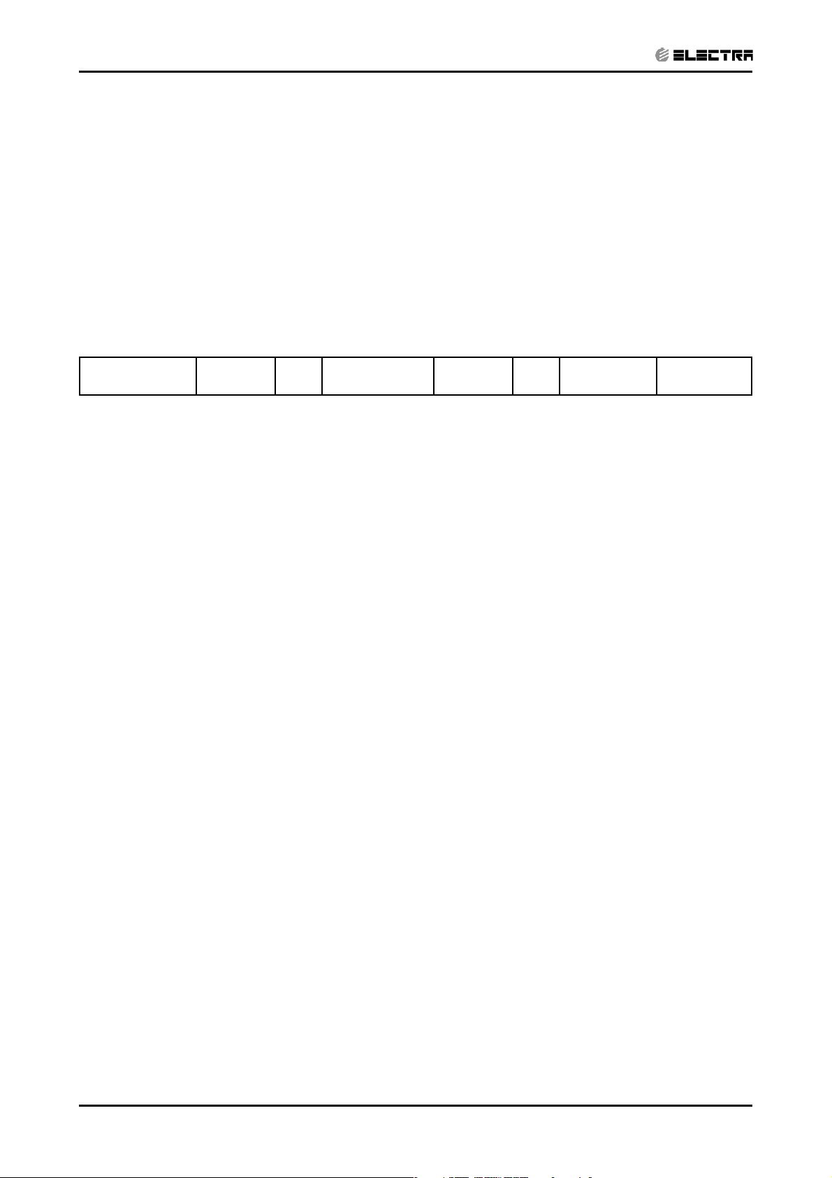
Service Manual
DNG series
Indoor Units Outdoor Units
DNG 18 GC18
DNG 24 OU7-24
DNG 30 OU8-30
DNG 37 OU10-36
DNG 44 OU10-44
REFRIGERANT
R410A
FEBRUARY 2005
HEAT PUMP
COOLING ONLY
LIST OF EFFECTIVE PAGES
LIST OF EFFECTIVE PAGES
Note: Changes in the pages are indicated by a “Revision#” in the footer of each effected page
(when none indicates no changes in the relevant page). All pages in the following list represent
effected/ non effected pages divided by chapters.
Dates of issue for original and changed pages are:
Original ....... 0 ........ 24 February 2005
Total number of pages in this publication is 139 consisting of the following:
Page
No.
Title ....................... 0
A ........................... 0
i ............................. 0
1-1 - 1-4 ................ 0
2-1 - 2-4 ................ 0
3-1 - 3-2 ................ 0
4-1 - 4-2 ................ 0
5-1 - 5-12 .............. 0
6-1 - 6-8 ................ 0
7-1 - 7-2 ................ 0
8-1 - 8-2 ................ 0
9-1 - 9-2 ................ 0
10-1-10-2 .............. 0
• Zero in this column indicates an original page.
Revision
No. #
Page
No.
Revision
No. #
Page
No.
Revision
No. #
*Due to constant improvements please note that the data on this service manual can be modified with out notice.
**Photos are not contractual.
A
Revision Y05-01
DATA BOOK - DNG Series
TABLE OF CONTENTS
Table of Contents
1. INTRODUCTION ...................................................................................................1-1
2. PRODUCT DATA SHEET ......................................................................................2-1
3. RATING CONDITIONS ..........................................................................................3-1
4. OUTLINE DIMENSIONS .......................................................................................4-1
5. PERFORMANCE DATA & PRESSURE CURVES ................................................5-1
6. AIRFLOW CURVES ..............................................................................................6-1
7. SOUND LEVEL CHARACTERISTICS ..................................................................7-1
8. ELECTRICAL DATA ..............................................................................................8-1
9. WIRING DIAGRAMS .............................................................................................9-1
10. ELECTRICAL CONNECTIONS .............................................................................10-1
11. REFRIGERATION DIAGRAMS .............................................................................11-1
12. TUBING CONNECTIONS ......................................................................................12-1
13. CONTROL SYSTEM .............................................................................................13-1
14. TROUBLESHOOTING ..........................................................................................14-1
15. EXPLODED VIEWS AND SPARE PARTS LISTS .................................................15-1
16. APPENDIX A .........................................................................................................16-1
Service Manual - DNG Series
Revision Y05-01
i
1. INTRODUCTION
CONTENT
1.1 General
The new DNG ducted split unit range comprises the ST (cooling only) as well as RC
(heat pump) models, it is available at 1PH, 3PH as follow:
• 1PH DNG 18, 24, 30, 37
• 3PH DNG 18, 24, 30, 37, 44
Remote control compatibility
• The DNG unit is compatible with remote controls RC3, RC4, RCW1, RCW2
1.2 Main Features
INTRODUCTION
The DNG series benefits from the most advanced technological innovations, namely:
• R410A refrigerant for all the range.
• The only Single Fan, medium capacity, low silhouette ducted unit
• High Static Pressure in the low silhouette category.
• Low indoor and outdoor sound level
• Low Silhouette 260-300mm height that simplify the false ceiling construction.
• Small volume, easy for installation (require small space for installation)
• Water drainage capability without siphon near the unit.
• Built in over-flow protection against condensate water
• 50 meters pipes installation in charge-less system
• High COP by switching to R 410A and enlarging indoor coil sizes
• Complies with M1 regulations
• Compatible with Saginomya “all season kit” that permits operation in cooling
mode up to -5ºC outdoor temperature.
• Easy service access by removing the drain pan.
• Microprocessor control.
• Infrared remote control with liquid crystal display.
Revision Y05-01Service Manual - DNG Series
1-1
INTRODUCTION
CONTENT
1.3 Indoor Unit
The indoor unit can fit easily to many types of residential and commercials applications.
It includes:
• High technology plastic fan and fan housing.
• A drain pool that is under the entire unit with internal downward slope.
• An over-flow switch that stops compressor operation in case drainage tube is
blocked.
• A bended coil with treated aluminium fins.
• 3-speed fan motor with internal protection with extra speed for higher external
static pressure.
• Advanced electronic control box assembly with 1.8-meter cable to allow
installation at a more accessible area.
• All the tubing connections are in the back of the unit to allow easy outlet to left
or right side of the unit.
• Field options:
(1) Electrical Heaters for 2005
(2) External water pump
(3) Airconet connection
(4) Plenum kit for connection of flexible hoses at air outlet.
1.4 Filtration
• The unit is equipped with pre-filters.
• Easy and versitile access, rear or buttom, can be easily adjusted by the
installer.
1.5 Ioniser (Optional)
A special design Ioniser protected by unique patents integrated into the indoor unit,
generating negative ions to the room providing comfort and upgraded indoor air quality.
1.6 Control
The microprocessor indoor controller, and an infrared remote control, supplied as
standard, provides complete operating function and programming. For further details,
please refer to the Operation Manual,
1-2
Revision Y05-01 Service Manual - DNG Series
1.7 Outdoor Unit
CONTENT
The DNG outdoor units can be installed as floor or wall mounted units by using a
wall-supporting bracket. The metal sheets are protected by anti- corrosion paintwork
allowing long life resistance. All outdoor units are pre-charged. For further information,
please refer to the Product Data Sheet, Chapter 2.
It includes:
• Compressor mounted in a soundproofed compartment :
Rotary – for DNG 18, 24, 30, 37
Scroll – for DNG 44
• Improved 3- blades axial fans for noise reduction.
• Outdoor coil with hydrophilic fins for RC units optimised for operation with R
410A refrigerant.
• Fan grill air outlet.
INTRODUCTION
• Service valves” flare” type connection.
• Service ports for high/ low pressure measurement.
• Interconnecting wiring terminal block.
1.8 Tubing Connections
Flare type-interconnecting tubing to be produced on site.
All the units from 7KW and up can be installed with 50-meter pipe length and 25 meter
height difference without oil traps.
For further details, please refer to the Installation Manual.
1.9 Accessories
ASK (All Season Kit):
For low ambient working conditions in cooling, an ASK can be installed inside the
outdoor unit. This kit allows cooling operation down to outdoor temperature of -10 ºC by
gradually controlling the outdoor fan speed motor.
RCW Wall Mounted Remote Control
The RCW remote control is mounted on the wall, and controls the unit either as an
infrared remote control or as a wired controller. The wired controller can control up to
10 Indoor units with the same program settings and adjustments.
For further details, please refer to the Technical Service Manual.
1.10 Inbox Documentation
Each unit includes its own installation and operation manuals.
Revision Y05-01Service Manual - DNG Series
1-3
2. PRODUCT DATA SHEET
CONTENT
2.1 R410C
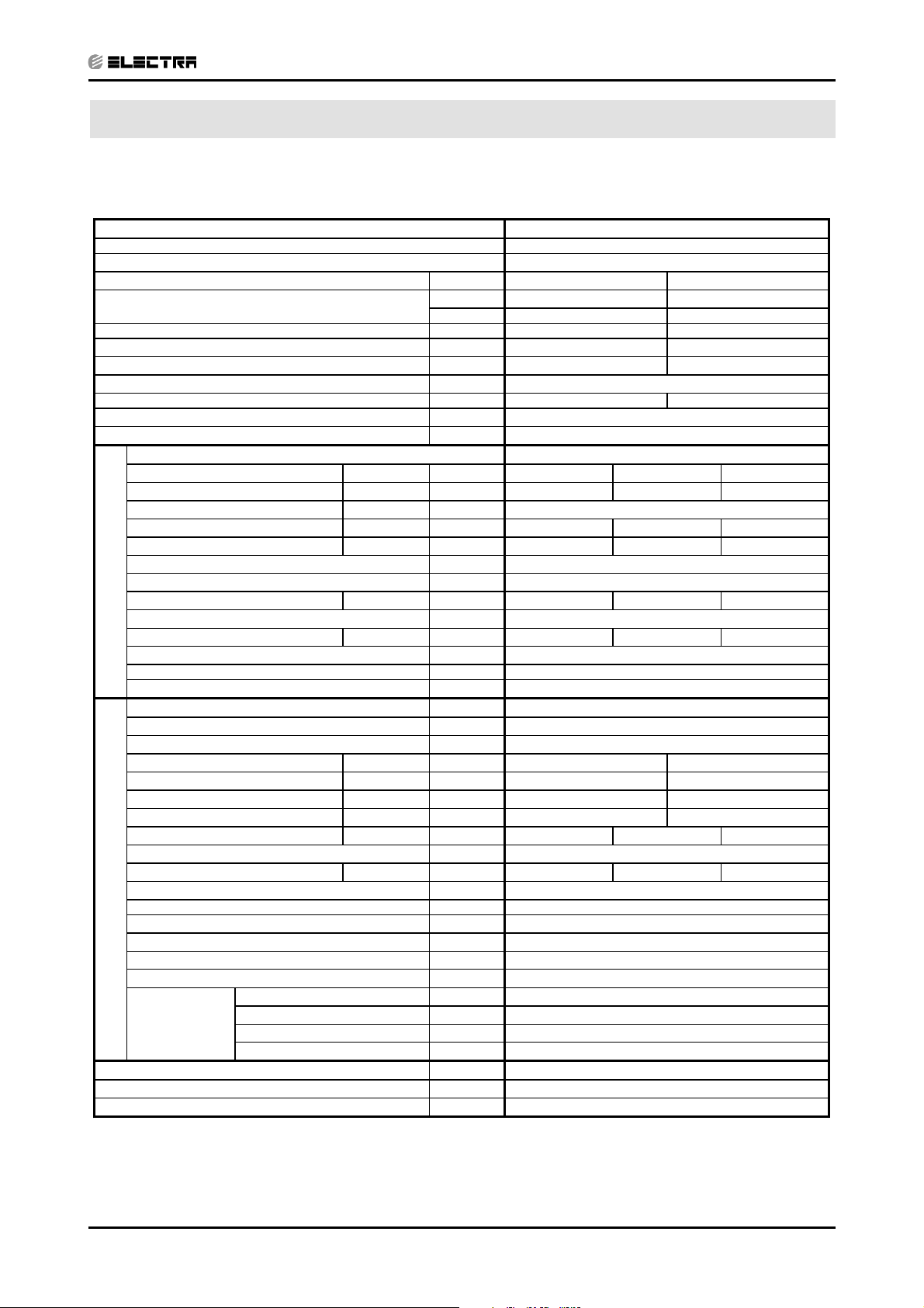
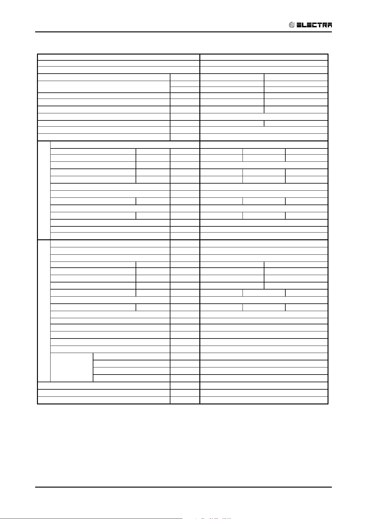
PRODUCT DATA SHEET
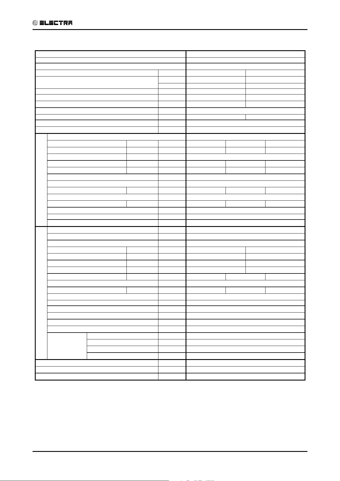
Model Indoor Unit
Model Outdoor Unit GC 18 R410A
Installation Method DUCTED
Characteristics Units Cooling Heating
Capacity
Power Input
COP
Energy Efficiency Class B D
Power Supply V/Ph/Hz 230/50/1
Rated Current A 8.2 7.5
Starting Current A 43
Circuit Breaker Rating A 20
Operation Control Type
Heating Elements kW
Others
(1)
(1)
(1)
INDOOR
OUTDOOR
kW 1.8 1.7
W/W 3.05 3.12
Fan Type & Quantity
Fan Speed H/M/L RPM 630 530 425
(2)
Airflow
H/M/L m3/hr 1150 875 730
External Static Pressure Min-Max Pa 25-60
Sound Power Level
Sound Pressure Level
Moisture Removal L/hr 2.0
Condensate Drain Tube I.D. mm 22
Dimensions W/H/D mm 770 260 690
Weight kg 29
Package Dimensions W/H/D mm 959 315 854
Packaged Weight kg 31
Units per Pallet Units 6
Stacking Height Units 6
Refrigerant Control
Compressor Type, Model Rotary
Fan Type & Quantity Axial & 1
Fan Speeds H/L RPM 815
Airflow H/L m3/hr 2480
Sound Power Level H/L dB (A) 68
Sound Pressure Level
Dimensions W/H/D mm 846 690 302
Weight kg 56
Package Dimensions W/H/D mm 990 770 430
Packaged Weight kg 61
Units per Pallet Units 9
Stacking Height Units 3
Refrigerant Type R 410A
Refrigerant Chargeless Distance kg/m 1.75/10
Additional Charge Per 1 Meter g/m 25
Connections
Between Units
(3)
H/M/L dB (A) 55 53 50
(4)
H/M/L dB (A) 45 42 40
(4)
H/L dB (A) 58
Liquid Line In 1/4
Suction Line In 1/2
Max. Tubing Length m 25
Max. Height Difference m 15
Btu/hr 19100 18000
kW 5.6 5.3
DNG 18
CENTRIFUGAL X1
Capillary
LCD Remote Control
1) Rating conditions in accordance with ISO 5151 and ISO 13253 (for ducted units) and EN14511.
(2) Airflow in ducted units; at nominal external static pressure.
(3) Sound power in ducted units is measured at air discharge.
(4) Sound pressure level measured at 1 meter distance from unit.
Revision Y05-01Service Manual - DNG Series
2-1
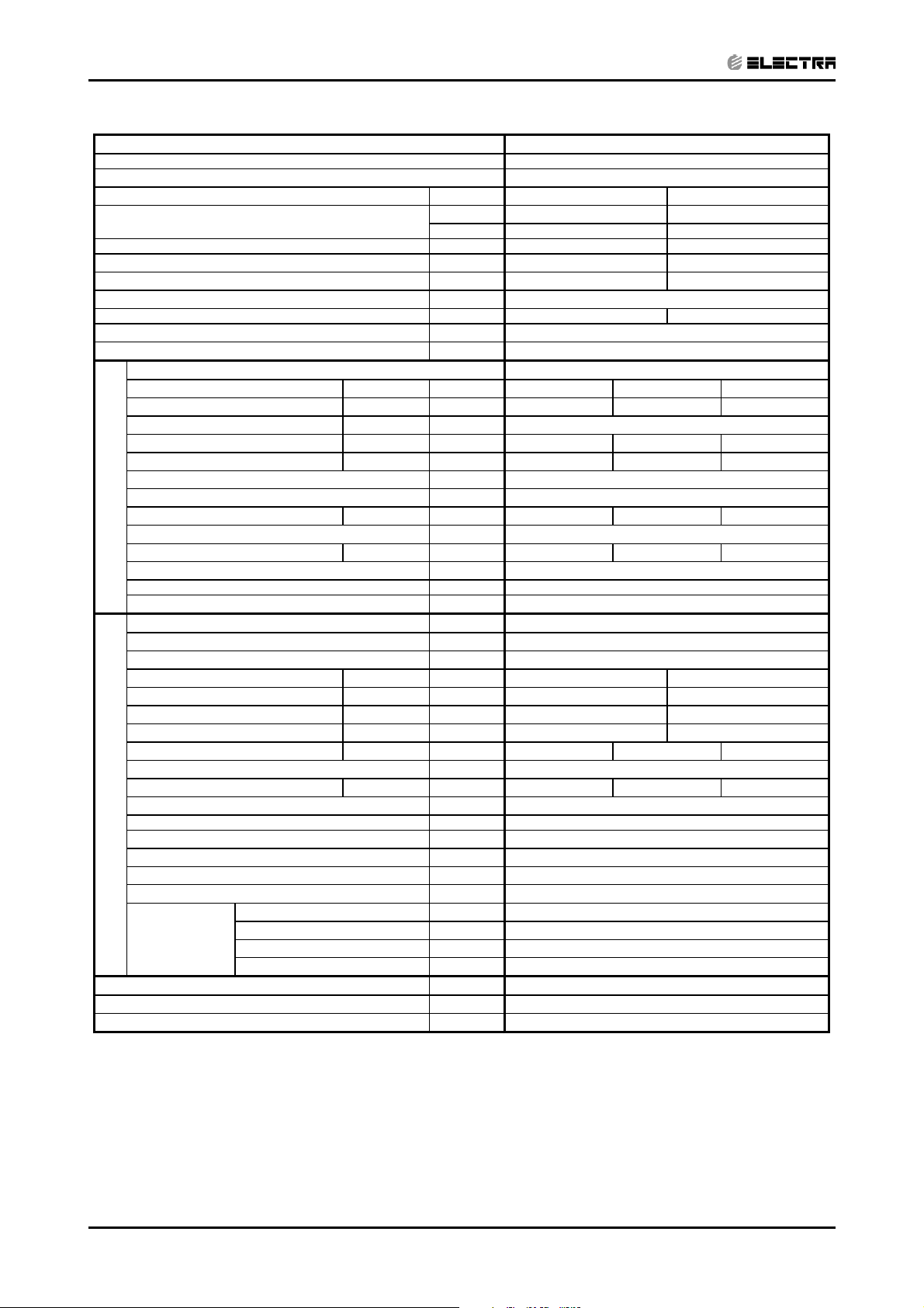
PRODUCT DATA SHEET
CONTENT
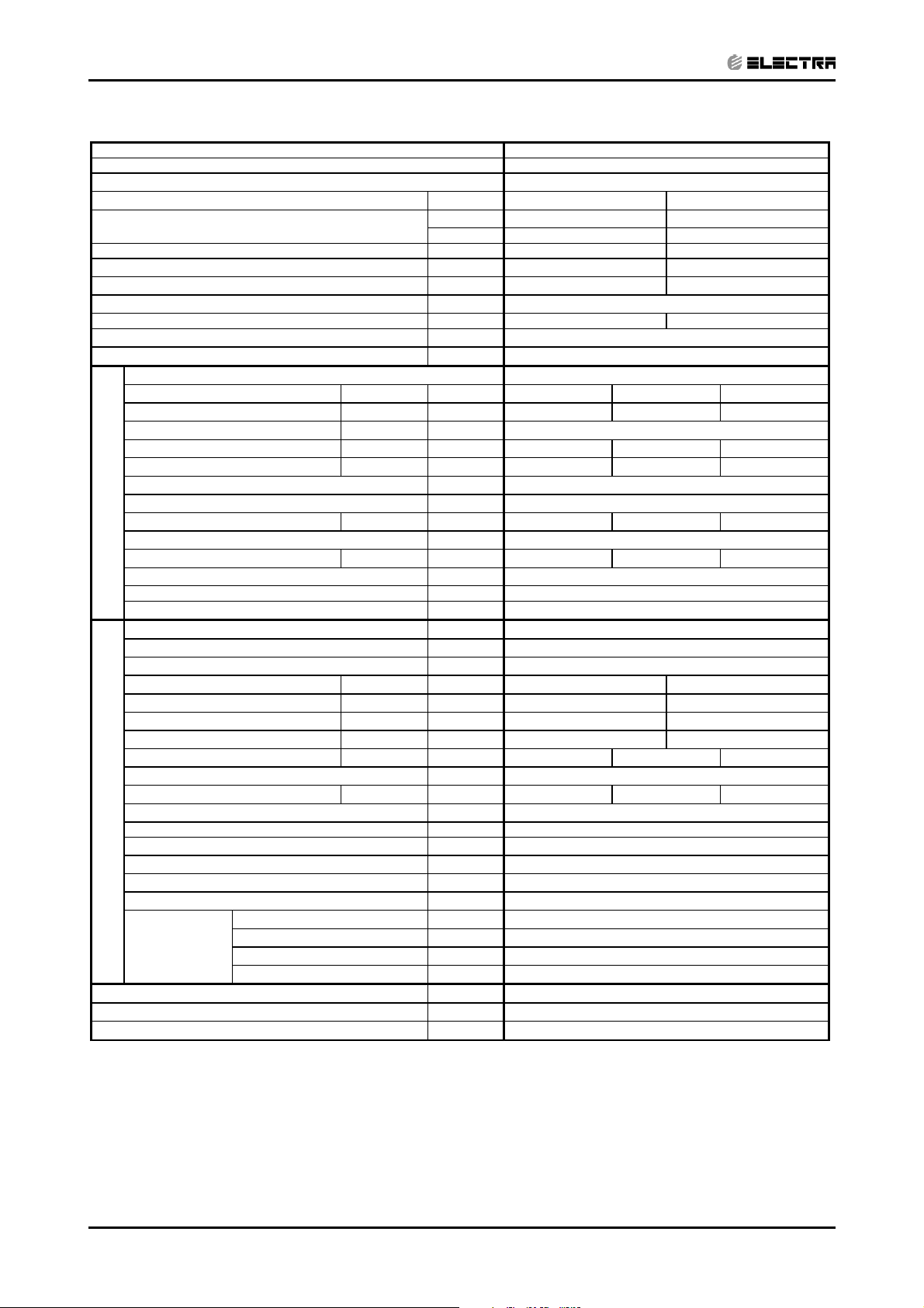
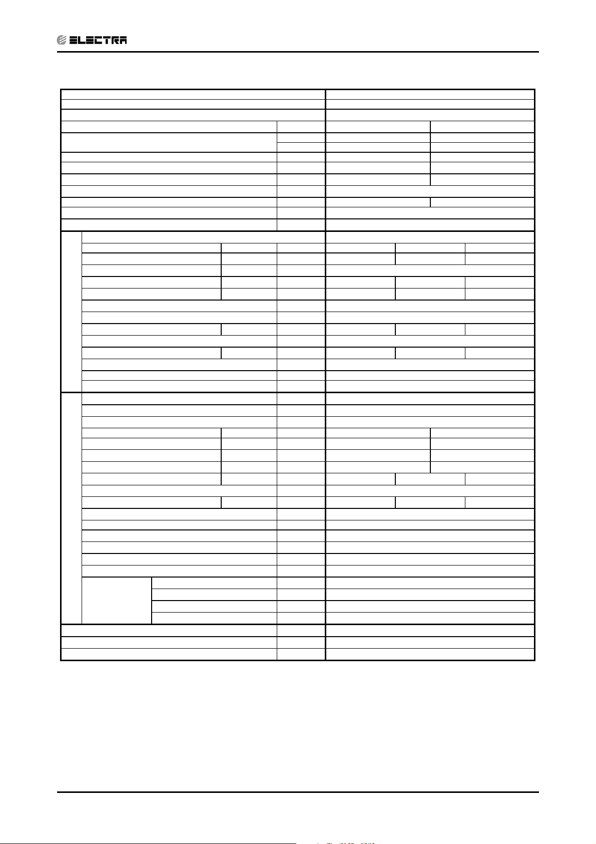
Model Indoor Unit
DNG 18
Model Outdoor Unit GC 18 3PH R410A
Installation Method DUCTED
Characteristics Units Cooling Heating
Capacity
Power Input
COP
(1)
(1)
(1)
kW 1.8 1.7
W/W 3.05 3.12
Btu/hr 19100 18000
kW 5.6 5.3
Energy Efficiency Class B D
Power Supply V/Ph/Hz 400/50/1
Rated Current A 3*3.5 3*3.1
Starting Current A 26
Circuit Breaker Rating A 3*10
Fan Type & Quantity
Fan Speed H/M/L RPM 630 530 425
(2)
Airflow
H/M/L m3/hr 1150 875 730
External Static Pressure Min-Max Pa 25-60
Sound Power Level
Sound Pressure Level
(3)
H/M/L dB (A) 55 53 50
(4)
H/M/L dB (A) 45 42 40
CENTRIFUGAL X1
Moisture Removal L/hr 2.0
Condensate Drain Tube I.D. mm 22
INDOOR
Dimensions W/H/D mm 770 260 690
Weight kg 29
Package Dimensions W/H/D mm 959 315 854
Packaged Weight kg 31
Units per Pallet Units 6
Stacking Height Units 6
Refrigerant Control
Capillary
Compressor Type, Model Rotary
Fan Type & Quantity Axial & 1
Fan Speeds H/L RPM 815
Airflow H/L m3/hr 2480
Sound Power Level H/L dB (A) 68
Sound Pressure Level
(4)
H/L dB (A) 58
Dimensions W/H/D mm 846 690 302
Weight kg 56
Package Dimensions W/H/D mm 990 770 430
Packaged Weight kg 61
OUTDOOR
Units per Pallet Units 9
Stacking Height Units 3
Refrigerant Type R 410A
Refrigerant Chargeless Distance kg/m 1.98/10
Additional Charge Per 1 Meter g/m 25
Liquid Line In 1/4
Connections
Between Units
Suction Line In 1/2
Max. Tubing Length m 25
Max. Height Difference m 15
Operation Control Type
LCD Remote Control
Heating Elements kW
Others
1) Rating conditions in accordance with ISO 5151 and ISO 13253 (for ducted units) and EN14511.
(2) Airflow in ducted units; at nominal external static pressure.
(3) Sound power in ducted units is measured at air discharge.
(4) Sound pressure level measured at 1 meter distance from unit.
2-2
Revision Y05-01 Service Manual - DNG Series
PRODUCT DATA SHEET
CONTENT
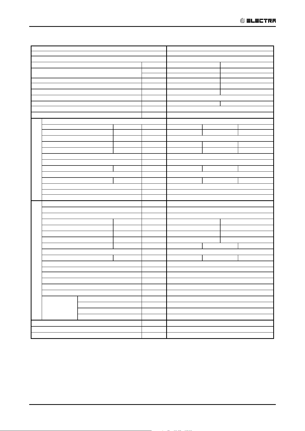
Model Indoor Unit
DNG 24
Model Outdoor Unit OU7-24 R410A
Installation Method DUCTED
Characteristics Units Cooling Heating
Capacity
Power Input
COP
(1)
(1)
(1)
kW 2.4 2.3
W/W 2.9 3.04
Btu/hr 23500 23850
kW 6.9 7.0
Energy Efficiency Class C D
Power Supply V/Ph/Hz 230/50/1
Rated Current A 10.8 10.5
Starting Current A 66
Circuit Breaker Rating A 20
Fan Type & Quantity
Fan Speed H/M/L RPM 680 630 530
(2)
Airflow
H/M/L m3/hr 1210 1100 840
External Static Pressure Min-Max Pa 25-60
Sound Power Level
Sound Pressure Level
(3)
H/M/L dB (A) 60 58 55
(4)
H/M/L dB (A) 48 45 43
CENTRIFUGAL X1
Moisture Removal L/hr 2.3
Condensate Drain Tube I.D. mm 22
INDOOR
Dimensions W/H/D mm 770 260 690
Weight kg 29
Package Dimensions W/H/D mm 959 315 854
Packaged Weight kg 31
Units per Pallet Units 6
Stacking Height Units 6
Refrigerant Control
Capillary
Compressor Type, Model Rotary
Fan Type & Quantity Axial & 1
Fan Speeds H/L RPM 850
Airflow
Sound Power Level H/L dB (A) 67
Sound Pressure Level
(4)
H/L dB (A) 58
H/L m
3
/hr 3100
Dimensions W/H/D mm 900 680 340
Weight kg 78
Package Dimensions W/H/D mm 985 730 435
Packaged Weight kg 82
OUTDOOR
Units per Pallet Units 6
Stacking Height Units 2
Refrigerant Type R 410A
Refrigerant Chargeless Distance kg/m 2,16/ 12.5
Additional Charge Per 1 Meter g/m 25
Liquid Line In 3/8
Connections
Between Units
Suction Line In 5/8
Max. Tubing Length m 50
Max. Height Difference m 25
Operation Control Type
LCD Remote Control
Heating Elements kW
Others Crankcase heater (50W)
1) Rating conditions in accordance with ISO 5151 and ISO 13253 (for ducted units) and EN14511.
(2) Airflow in ducted units; at nominal external static pressure.
(3) Sound power in ducted units is measured at air discharge.
(4) Sound pressure level measured at 1 meter distance from unit.
Revision Y05-01Service Manual - DNG Series
2-3
PRODUCT DATA SHEET
CONTENT
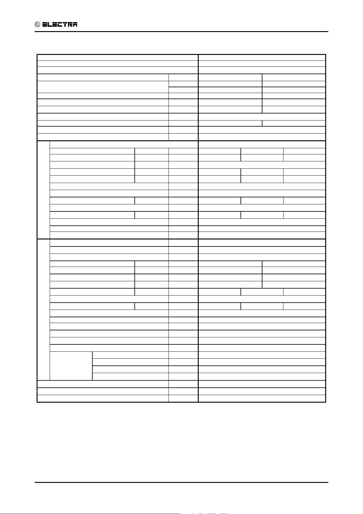
Model Indoor Unit DNG 24
Model Outdoor Unit OU7-24T R410A
Installation Method DUCTED
Characteristics Units Cooling Heating
Capacity
Power Input
COP
(1)
(1)
(1)
kW 2.4 2.3
W/W 2.9 3.03
Energy Efficiency Class C D
Power Supply V/Ph/Hz 400/50/3
Rated Current A 3*6.0 3*5.4
Starting Current A
Circuit Breaker Rating A 3*10
Fan Type & Quantity
Fan Speed H/M/L RPM 680 630 530
(2)
Airflow
H/M/L m3/hr 1210 1100 840
External Static Pressure Min-Max Pa 25-60
Sound Power Level
Sound Pressure Level
(3)
H/M/L dB (A) 60 58 55
(4)
H/M/L dB (A) 48 45 43
Moisture Removal L/hr 2.3
Condensate Drain Tube I.D. mm 22
INDOOR
Dimensions W/H/D mm 770 260 690
Weight kg 29
Package Dimensions W/H/D mm 959 315 854
Packaged Weight kg 31
Units per Pallet Units 6
Stacking Height Units 6
Refrigerant Control
Compressor Type, Model Rotary
Fan Type & Quantity Axial & 1
Fan Speeds H/L RPM 850
Airflow
Sound Power Level H/L dB (A) 67
Sound Pressure Level
(4)
H/L dB (A) 58
H/L m
Dimensions W/H/D mm 900 680 340
Weight kg 78
Package Dimensions W/H/D mm 985 730 435
Packaged Weight kg 82
OUTDOOR
Units per Pallet Units 6
Stacking Height Units 2
Refrigerant Type R 410A
Refrigerant Chargeless Distance kg/m 2,16/ 12.5
Additional Charge Per 1 Meter g/m 25
Liquid Line In 3/8
Connections
Between Units
Suction Line In 5/8
Max. Tubing Length m 50
Max. Height Difference m 25
Operation Control Type
Heating Elements kW
Others Crankcase heater (50W), 3 Phase Protector
Btu/hr 23500 23850
kW 6.9 7.0
CENTRIFUGAL X1
Capillary
3
/hr 3100
LCD Remote Control
1) Rating conditions in accordance with ISO 5151 and ISO 13253 (for ducted units) and EN14511.
(2) Airflow in ducted units; at nominal external static pressure.
(3) Sound power in ducted units is measured at air discharge.
(4) Sound pressure level measured at 1 meter distance from unit.
2-4
Revision Y05-01 Service Manual - DNG Series

PRODUCT DATA SHEET
CONTENT
Model Indoor Unit DNG 30
Model Outdoor Unit OU8-30 R410A
Installation Method DUCTED
Characteristics Units Cooling Heating
Capacity
Power Input
COP
(1)
(1)
(1)
kW 3.0 2.8
W/W 2.81 3.22
Energy Efficiency Class C C
Power Supply V/Ph/Hz 230/50/1
Rated Current A 13.7 12.5
Starting Current A 80
Circuit Breaker Rating A 25
Fan Type & Quantity
Fan Speed H/M/L RPM 800 670 550
(2)
Airflow
H/M/L M3/hr 1420 1150 935
External Static Pressure Min-Max Pa 37-80
Sound Power Level
Sound Pressure Level
(3)
H/M/L dB (A) 64 61 58
(4)
H/M/L dB (A) 49 46 44
Moisture Removal L/hr 3.0
Condensate Drain Tube I.D. mm 22
INDOOR
Dimensions W/H/D mm 770 260 690
Weight kg 31
Package Dimensions W/H/D mm 959 315 854
Packaged Weight kg 33
Units per Pallet Units 6
Stacking Height Units 6
Refrigerant Control
Compressor Type, Model Rotary
Fan Type & Quantity Axial & 1
Fan Speeds H/L RPM 850
Airflow
Sound Power Level H/L dB (A) 66
Sound Pressure Level
(4)
H/L dB (A) 58
H/L M
Dimensions W/H/D mm 900 860 340
Weight kg 78
Package Dimensions W/H/D mm 985 907 435
Packaged Weight kg 82
OUTDOOR
Units per Pallet Units 6
Stacking Height Units 2
Refrigerant Type R 410A
Refrigerant Chargeless Distance kg/m 2.42/ 15
Additional Charge Per 1 Meter g/m 25
Liquid Line In 3/8
Connections
Between Units
Suction Line In 5/8
Max. Tubing Length m 50
Max. Height Difference m 25
Operation Control Type
Heating Elements kW
Others Crankcase heater (50W)
Btu/hr 29000 30700
kW 8.5 9.0
CENTRIFUGAL X1
Capillary
3
/hr 3150
LCD Remote Control
1) Rating conditions in accordance with ISO 5151 and ISO 13253 (for ducted units) and EN14511.
(2) Airflow in ducted units; at nominal external static pressure.
(3) Sound power in ducted units is measured at air discharge.
(4) Sound pressure level measured at 1 meter distance from unit.
Revision Y05-01Service Manual - DNG Series
2-5
PRODUCT DATA SHEET
CONTENT
Model Indoor Unit DNG 30
Model Outdoor Unit OU8-30T R410A
Installation Method DUCTED
Characteristics Units Cooling Heating
Capacity
Power Input
COP
(1)
(1)
(1)
kW 3.0 2.8
W/W 2.82 3.24
Energy Efficiency Class C C
Power Supply V/Ph/Hz 400/50/3
Rated Current A 3*7.5 3*7.1
Starting Current A 35
Circuit Breaker Rating A 3*16
Fan Type & Quantity
Fan Speed H/M/L RPM 800 670 550
(2)
Airflow
H/M/L M3/hr 1420 1150 935
External Static Pressure Min-Max Pa 37-80
Sound Power Level
Sound Pressure Level
(3)
H/M/L dB (A) 64 61 58
(4)
H/M/L dB (A) 49 46 44
Moisture Removal L/hr 3.0
Condensate Drain Tube I.D. mm 22
INDOOR
Dimensions W/H/D mm 770 260 690
Weight kg 31
Package Dimensions W/H/D mm 959 315 854
Packaged Weight kg 33
Units per Pallet Units 6
Stacking Height Units 6
Refrigerant Control
Compressor Type, Model Rotary
Fan Type & Quantity Axial & 1
Fan Speeds H/L RPM 850
Airflow
Sound Power Level H/L dB (A) 66
Sound Pressure Level
(4)
H/L dB (A) 58
H/L M
Dimensions W/H/D mm 900 860 340
Weight kg 78
Package Dimensions W/H/D mm 985 907 435
Packaged Weight kg 82
OUTDOOR
Units per Pallet Units 6
Stacking Height Units 2
Refrigerant Type R 410A
Refrigerant Chargeless Distance kg/m 2.42/ 15
Additional Charge Per 1 Meter g/m 25
Liquid Line In 3/8
Connections
Between Units
Suction Line In 5/8
Max. Tubing Length m 50
Max. Height Difference m 25
Operation Control Type
Heating Elements kW
Others Crankcase heater (50W), 3 Phase Protector
Btu/hr 29000 30700
kW 8.5 9.0
CENTRIFUGAL X1
Capillary
3
/hr 3150
LCD Remote Control
1) Rating conditions in accordance with ISO 5151 and ISO 13253 (for ducted units) and EN14511.
(2) Airflow in ducted units; at nominal external static pressure.
(3) Sound power in ducted units is measured at air discharge.
(4) Sound pressure level measured at 1 meter distance from unit.
2-6
Revision Y05-01 Service Manual - DNG Series
PRODUCT DATA SHEET
CONTENT
Model Indoor Unit DNG 37
Model Outdoor Unit OU10-36 R410A
Installation Method DUCTED
Characteristics Units Cooling Heating
Capacity
Power Input
COP
(1)
(1)
(1)
kW 3.8 3.7
W/W 2.81 3.05
Energy Efficiency Class C D
Power Supply V/Ph/Hz 230/50/1
Rated Current A 16.9 16.3
Starting Current A 92
Circuit Breaker Rating A 25
Fan Type & Quantity
Fan Speed H/M/L RPM 775 650 540
(2)
Airflow
H/M/L M3/hr 1840 1520 1210
External Static Pressure Min-Max Pa 37-100
Sound Power Level
Sound Pressure Level
(3)
H/M/L dB (A) 67 63 60
(4)
H/M/L dB (A) 51 48 45
Moisture Removal L/hr 3.7
Condensate Drain Tube I.D. mm 22
INDOOR
Dimensions
W/H/D mm 835 300 755
Weight kg 33
Package Dimensions W/H/D mm 1010 342 917
Packaged Weight kg 35
Units per Pallet Units 6
Stacking Height Units 6
Refrigerant Control
Compressor Type, Model Rotary
Fan Type & Quantity Axial & 1
Fan Speeds H/L RPM 1125
Airflow
Sound Power Level H/L dB (A) 70.9
Sound Pressure Level
(4)
H/L dB (A) 63
H/L M
Dimensions W/H/D mm 900 970 340
Weight kg 87
Package Dimensions W/H/D mm 985 1020 435
Packaged Weight kg 91
Units per Pallet Units 6
OUTDOOR
Stacking Height Units 2
Refrigerant Type R 410A
Refrigerant Chargeless Distance kg/m 2.55/ 15
Additional Charge Per 1 Meter g/m 25
Liquid Line In 3/8
Connections
Between Units
Suction Line In 3/4
Max. Tubing Length m 50
Max. Height Difference m 25
Operation Control Type
Heating Elements kW
Others Crankcase heater (50W)
Btu/hr 36350 38200
kW 10.6 11.2
CENTRIFUGAL X1
Capillary
3
/hr 4150
LCD Remote Control
1) Rating conditions in accordance with ISO 5151 and ISO 13253 (for ducted units) and EN14511.
(2) Airflow in ducted units; at nominal external static pressure.
(3) Sound power in ducted units is measured at air discharge.
(4) Sound pressure level measured at 1 meter distance from unit.
Revision Y05-01Service Manual - DNG Series
2-7
PRODUCT DATA SHEET
CONTENT
Model Indoor Unit DNG 37
Model Outdoor Unit OU10-36T R410A
Installation Method DUCTED
Characteristics Units Cooling Heating
Capacity
Power Input
COP
(1)
(1)
(1)
kW 3.7 3.6
W/W 2.83 3.1
Energy Efficiency Class C D
Power Supply V/Ph/Hz 400/50/3
Rated Current A 3*10 3*9.6
Starting Current A 43
Circuit Breaker Rating A 3*16
Fan Type & Quantity
Fan Speed H/M/L RPM 775 650 540
(2)
Airflow
H/M/L M3/hr 1840 1520 1210
External Static Pressure Min-Max Pa 37-100
Sound Power Level
Sound Pressure Level
(3)
H/M/L dB (A) 67 63 60
(4)
H/M/L dB (A) 51 48 45
Moisture Removal L/hr 3.7
Condensate Drain Tube I.D. mm 22
INDOOR
Dimensions
W/H/D mm 835 300 755
Weight kg 33
Package Dimensions W/H/D mm 1010 342 917
Packaged Weight kg 35
Units per Pallet Units 6
Stacking Height Units 6
Refrigerant Control
Compressor Type, Model Rotary
Fan Type & Quantity Axial & 1
Fan Speeds H/L RPM 1125
Airflow
Sound Power Level H/L dB (A) 70.9
Sound Pressure Level
(4)
H/L dB (A) 63
H/L M
Dimensions W/H/D mm 900 970 340
Weight kg 87
Package Dimensions W/H/D mm 985 1020 435
Packaged Weight kg 91
Units per Pallet Units 6
OUTDOOR
Stacking Height Units 2
Refrigerant Type R 410A
Refrigerant Chargeless Distance kg/m 2.45/ 15
Additional Charge Per 1 Meter g/m 25
Liquid Line In 3/8
Connections
Between Units
Suction Line In 3/4
Max. Tubing Length m 50
Max. Height Difference m 25
Operation Control Type
Heating Elements kW
Others Crankcase heater (50W), 3 Phase Protector
Btu/hr 35480 37870
kW 10.4 11.1
CENTRIFUGAL X1
Capillary
3
/hr 4150
LCD Remote Control
1) Rating conditions in accordance with ISO 5151 and ISO 13253 (for ducted units) and EN14511.
(2) Airflow in ducted units; at nominal external static pressure.
(3) Sound power in ducted units is measured at air discharge.
(4) Sound pressure level measured at 1 meter distance from unit.
2-8
Revision Y05-01 Service Manual - DNG Series
PRODUCT DATA SHEET
CONTENT
Model Indoor Unit DNG44
Model Outdoor Unit OU10-44T R410A
Installation Method DUCTED
Characteristics Units Cooling Heating
Capacity
Power Input
COP
(1)
(1)
(1)
kW 4.6 4.5
W/W 2.7 3.03
Energy Efficiency Class D D
Power Supply V/Ph/Hz 400/50/3
Rated Current A 3*13.7 3*13.0
Starting Current A
Circuit Breaker Rating A 3*16
Fan Type & Quantity
Fan Speed H/M/L RPM 870 665 550
(2)
Airflow
H/M/L M3/hr 2040 1490 1250
External Static Pressure Min-Max Pa 50-100
Sound Power Level
Sound Pressure Level
(3)
H/M/L dB (A) 71 67 62
(4)
H/M/L dB (A) 52 49 47
Moisture Removal L/hr 4.4
Condensate Drain Tube I.D. mm 22
INDOOR
Dimensions
W/H/D mm 835 300 755
Weight kg 33
Package Dimensions W/H/D mm 1010 342 917
Packaged Weight kg 38
Units per Pallet Units 6
Stacking Height Units 6
Refrigerant Control
Compressor Type, Model Scroll
Fan Type & Quantity Axial & 1
Fan Speeds H/L RPM 1240
Airflow
Sound Power Level H/L dB (A) 72
Sound Pressure Level
(4)
H/L dB (A) 64
H/L M
Dimensions W/H/D mm 900 970 340
Weight kg 87
Package Dimensions W/H/D mm 985 1020 435
Packaged Weight kg 94
Units per Pallet Units 6
OUTDOOR
Stacking Height Units 2
Refrigerant Type R 410A
Refrigerant Chargeless Distance kg/m 2.92/ 15
Additional Charge Per 1 Meter g/m 25
Liquid Line In 3/8
Connections
Between Units
Suction Line In 3/4
Max. Tubing Length m 50
Max. Height Difference m 25
Operation Control Type
Heating Elements kW
Others Crankcase heater (50W), 3 Phase Protector
Btu/hr 42300 47000
kW 12.4 13.8
CENTRIFUGAL X1
Capillary
3
/hr 4500
LCD Remote Control
1) Rating conditions in accordance with ISO 5151 and ISO 13253 (for ducted units) and EN14511.
(2) Airflow in ducted units; at nominal external static pressure.
(3) Sound power in ducted units is measured at air discharge.
(4) Sound pressure level measured at 1 meter distance from unit.
Revision Y05-01Service Manual - DNG Series
2-9
3. RATING CONDITIONS
CONTENT
Standard conditions in accordance with ISO 5151 and ISO 13253 (for ducted units) and
EN 14511.
Cooling:
Indoor: 27oC DB 19oC WB
Outdoor: 35 oC DB
Heating:
Indoor: 20oC DB
Outdoor: 7oC DB 6oC WB
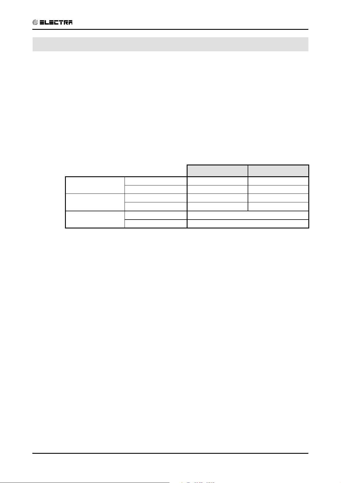
3.1 Operating Limits
Cooling
Heating
Voltage
Upper limit 32
Lower limit 21
Upper limit 27
Lower limit 20oC DB -9oC DB -10oC WB
1PH 198 – 242 V
3PH 360 – 440 V
RATING CONDITIONS
Indoor Outdoor
o
C DB 23oC WB 46oC DB
o
C DB 15oC WB 21oC DB
o
C DB 24oC DB 18oC WB
Revision Y05-01Service Manual - DNG Series
3-1
4. OUTLINE DIMENSIONS
CONTENT
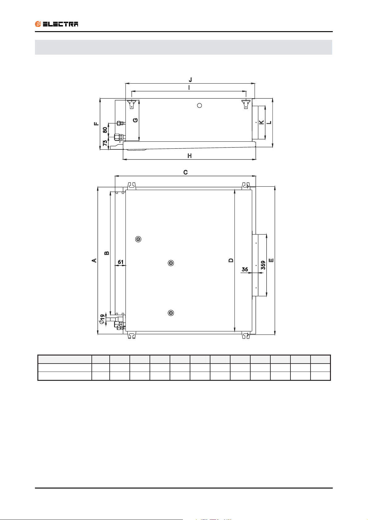
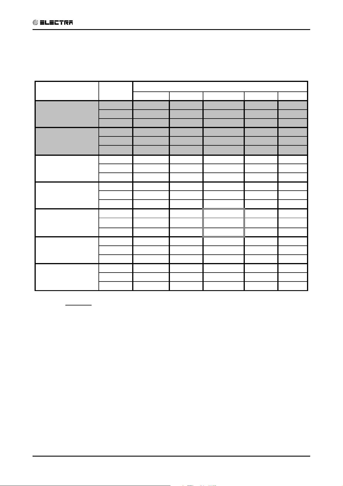
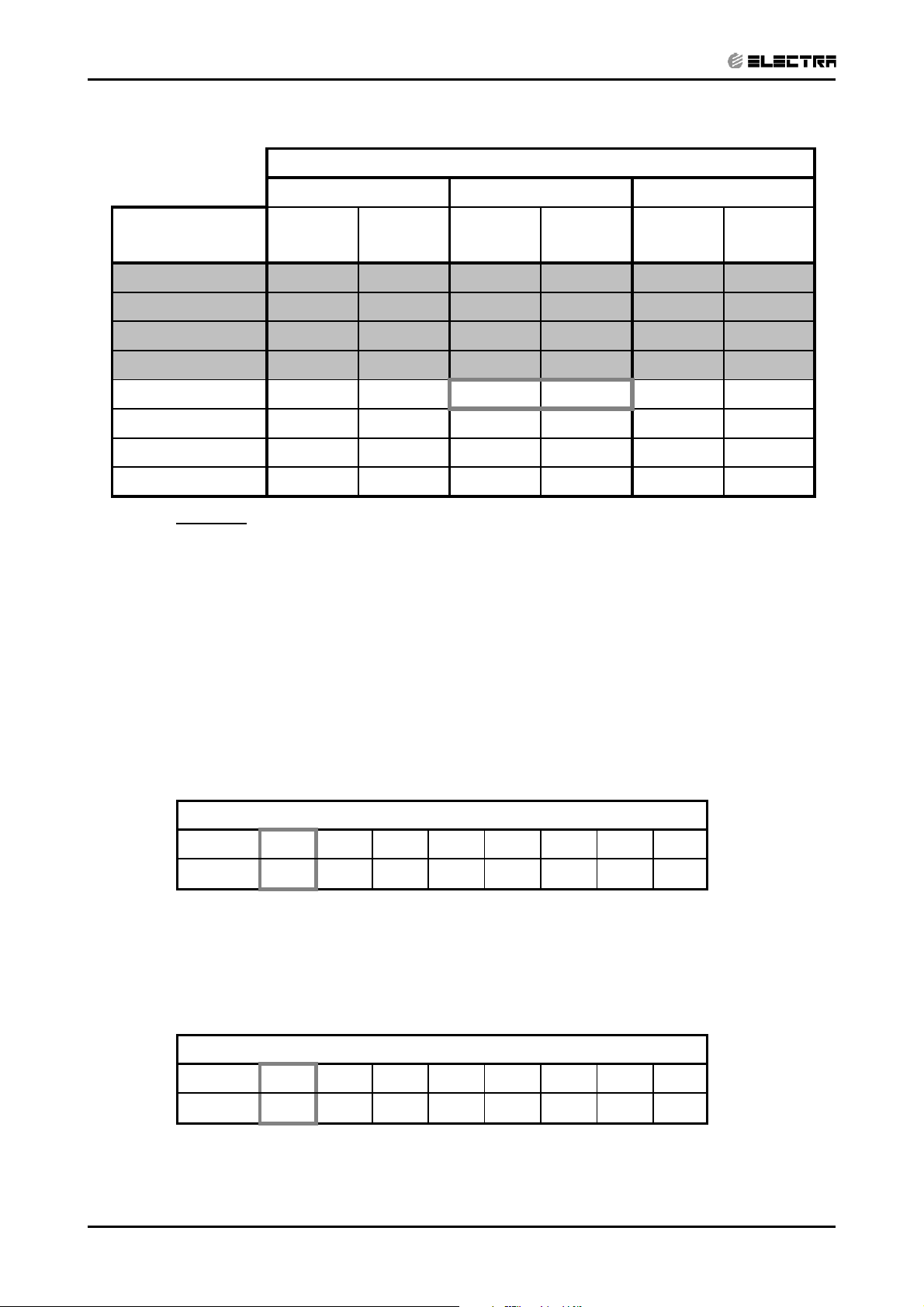
4.1 Indoor Unit: DNG 18, 24, 30, 37, 44
OUTLINE DIMENSIONS
Model A B C D E F G H I J K L
DNG 18,24,30
DNG 37,44
790 653 749 758 797 256 195 702 599 684 162 242
854 715 816 822 861 297 235 770 663 749 193 282
Revision Y05-01Service Manual - DNG Series
4-1
OUTLINE DIMENSIONS
CONTENT
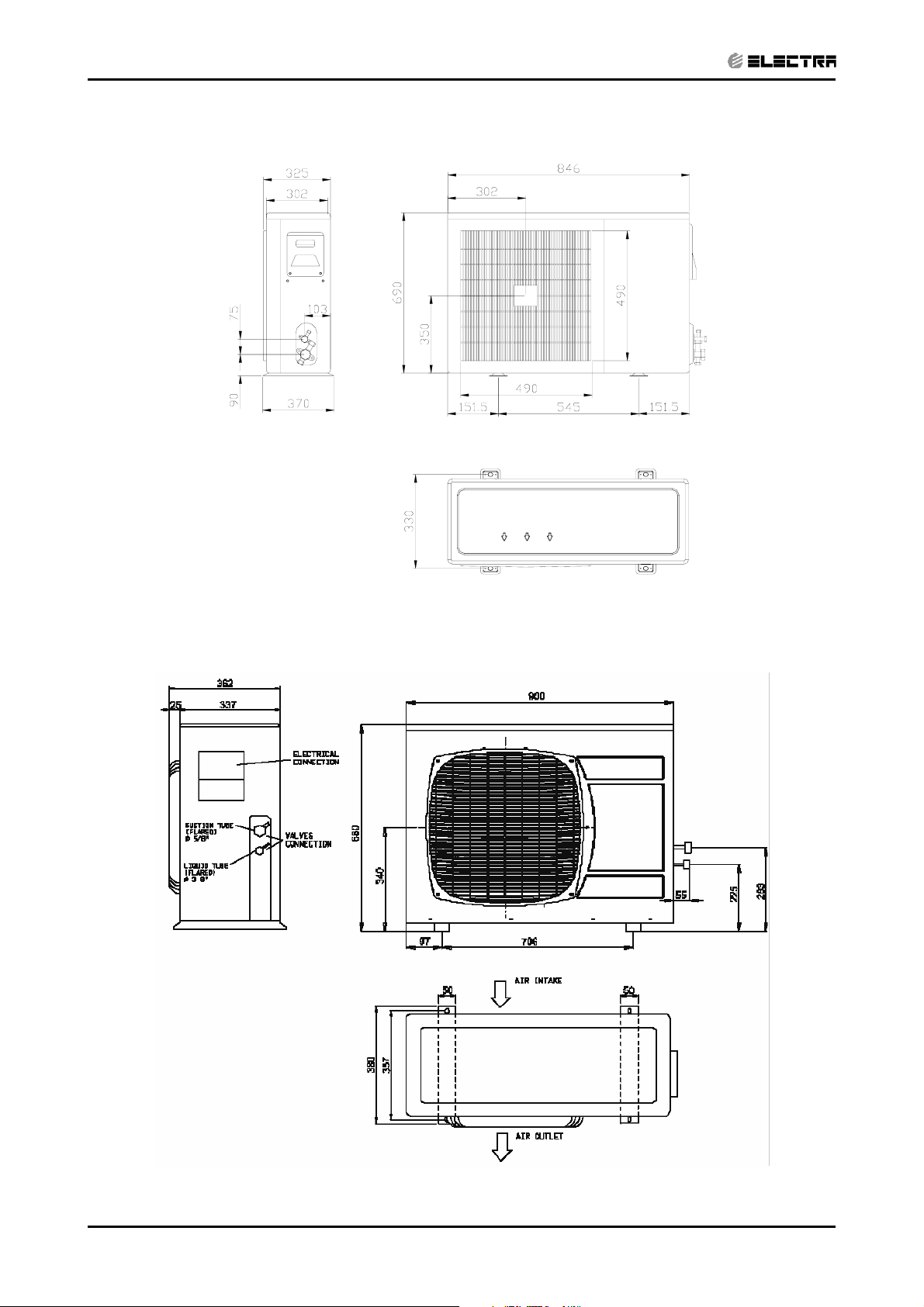
4.2 Outdoor Unit: GC 18
Outdoor Unit: OU7 24
4.3
4-2
Revision Y05-01 Service Manual - DNG Series
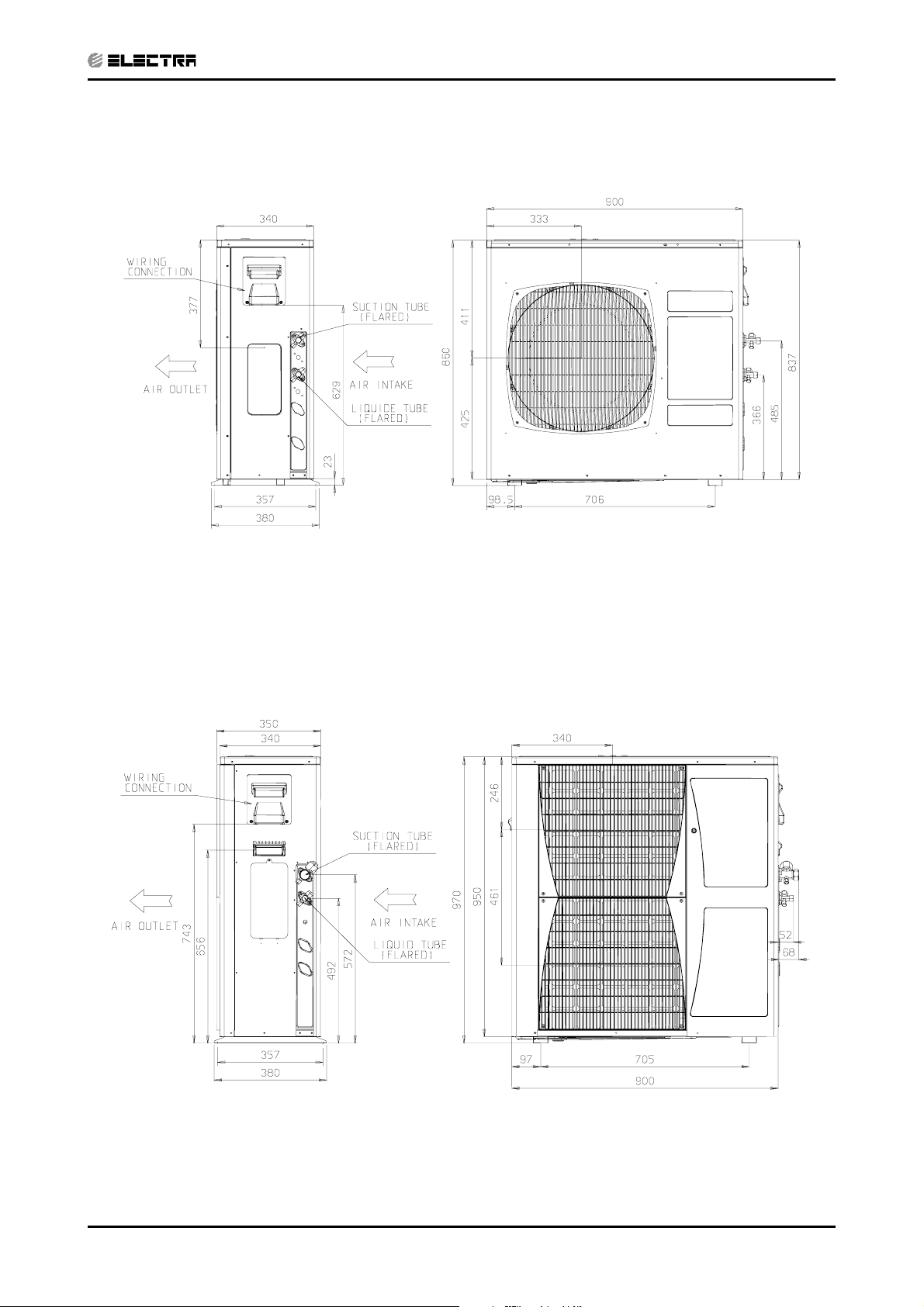
4.4 Outdoor Unit: OU8-33
CONTENT
OUTLINE DIMENSIONS
Outdoor Unit: OU10 36, 44
4.5
Revision Y05-01Service Manual - DNG Series
4-3
PERFORMANCE DATA & PRESSURE CURVES
CONTENT
5. PERFORMANCE DATA & PRESSURE CURVES
5.1 DNG 18, GC18 1PH / 3PH
5.1.1 Cooling Capacity (kW)
Entering Air DB
OD Coil(
o
C)
15 SC
20 SC
25 SC
30 SC
35 SC
40 SC
46 SC
Data
TC
PL
TC
PL
TC
PL
TC
PL
TC
PL
TC
PL
TC
PL
Entering Air WB/DB ID Coil(oC)
15/21 17/24 19/27 21/29 23/32
5.71 6.05 6.33 6.61 6.83
3.77 4.00 4.21 4.12 4.19
1.28 1.28 1.28 1.29 1.29
5.66 5.99 6.27 6.55 6.78
4.03 4.28 4.53 4.40 4.49
1.38 1.39 1.40 1.40 1.41
5.43 5.82 6.16 6.44 6.66
3.67 3.93 4.15 4.08 4.18
1.49 1.50 1.52 1.53 1.53
5.10 5.49 5.94 6.16 6.38
3.48 3.76 4.06 3.98 4.14
1.61 1.63 1.65 1.67 1.67
4.70 5.10
3.28 3.57
1.74 1.77
5.60
3.90
1.80
5.88 6.10
3.85 4.01
1.81 1.82
4.26 4.65 5.15 5.43 5.66
3.05 3.35 3.69 3.63 3.81
1.88 1.91 1.94 1.96 1.98
3.70 4.09 4.59 4.87 5.10
2.77 3.07 3.46 3.39 3.55
2.06 2.10 2.13 2.16 2.18
LEGEND
TC – Total Cooling Capacity, kW
SC – Sensible Capacity, kW
PI – Power Input, kW
WB – Wet Bulb Temp., (oC)
DB – Dry Bulb Temp., (
ID – Indoor
OD – Outdoor
o
C)
Revision Y05-01Service Manual - DNG Series
5-1
PERFORMANCE DATA & PRESSURE CURVES
CONTENT
5.1.2 Heating
ENTERING AIR DB ID COIL(Oc)
15 20 25
ENTERING WB
o
OD COIL(
C)
-10 3.06 1.36 2.94 1.45 2.83 1.52
-7 3.29 1.39 3.18 1.47 3.06 1.55
-2 3.50 1.41 3.38 1.50 3.26 1.58
2 4.26 1.48 4.08 1.57 3.91 1.67
6 5.46 1.59
10 5.94 1.68 5.78 1.79 5.62 1.92
15 6.41 1.75 6.25 1.89 6.10 2.01
20 6.76 1.80 6.60 1.96 6.41 2.11
LEGEND
TH – Total Heating Capacity, kW
PI – Power Input, kW
WB – Wet Bulb Temp., (oC)
DB – Dry Bulb Temp., (oC)
ID – Indoor
OD – Outdoor
TH Pl TH Pl TH Pl
5.30 1.70
5.11 1.81
5.2 Capacity Correction Factor Due to Tubing Length
5.2.1 Cooling
TOTAL TUBING LENGTH (One Way)
3m
1.01
7.5m
10m 15m 20m 25m 30m 40m 50m
1
0.97 0.96 0.95 0.94 --- --- ---
* Minimum recommended tubing length between indoor and outdoor units is 3m.
5.2.2 Heating
TOTAL TUBING LENGTH (One Way)
3m
1.02
7.5m
10m 15m 20m 25m 30m 40m 50m
1
0.98 0.97 0.95 0.93 --- --- ---
* Minimum recommended tubing length between indoor and outdoor units is 3m.
5-2
Revision Y05-01 Service Manual - DNG Series
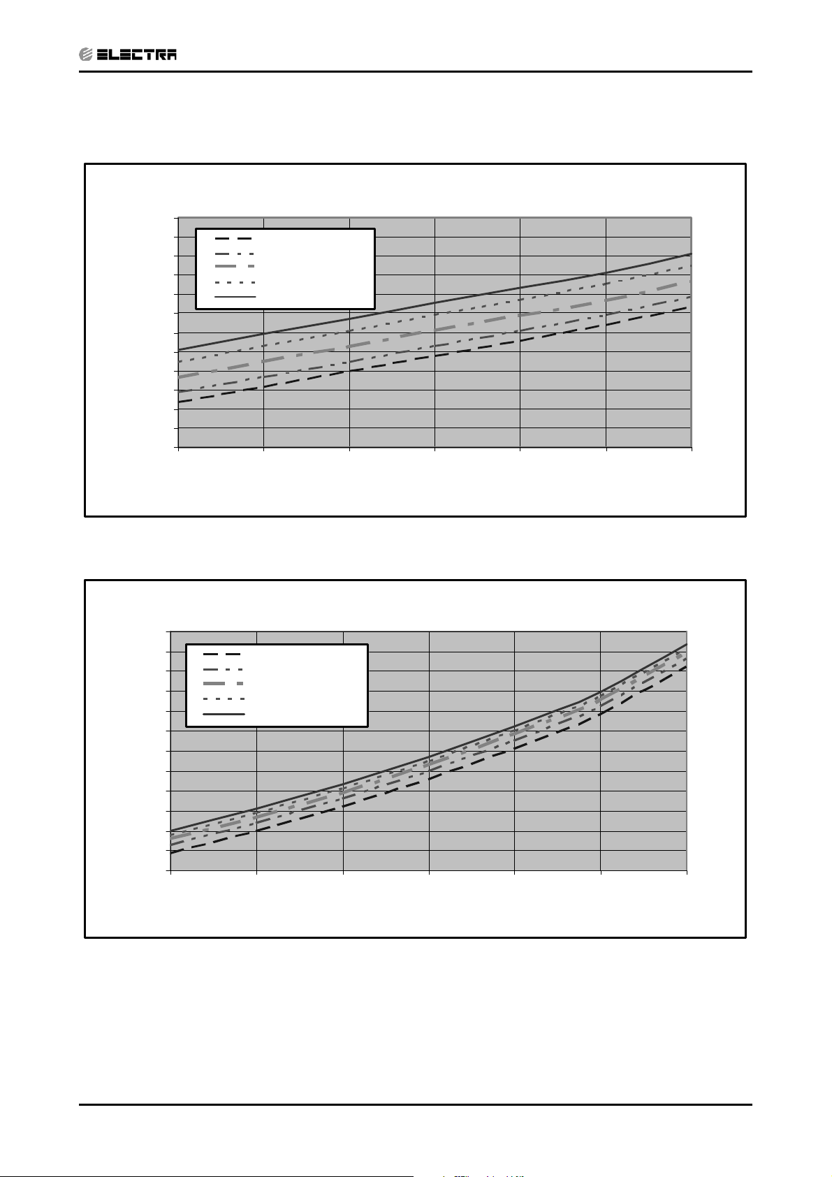
5.3 Pressure Curves
CONTENT
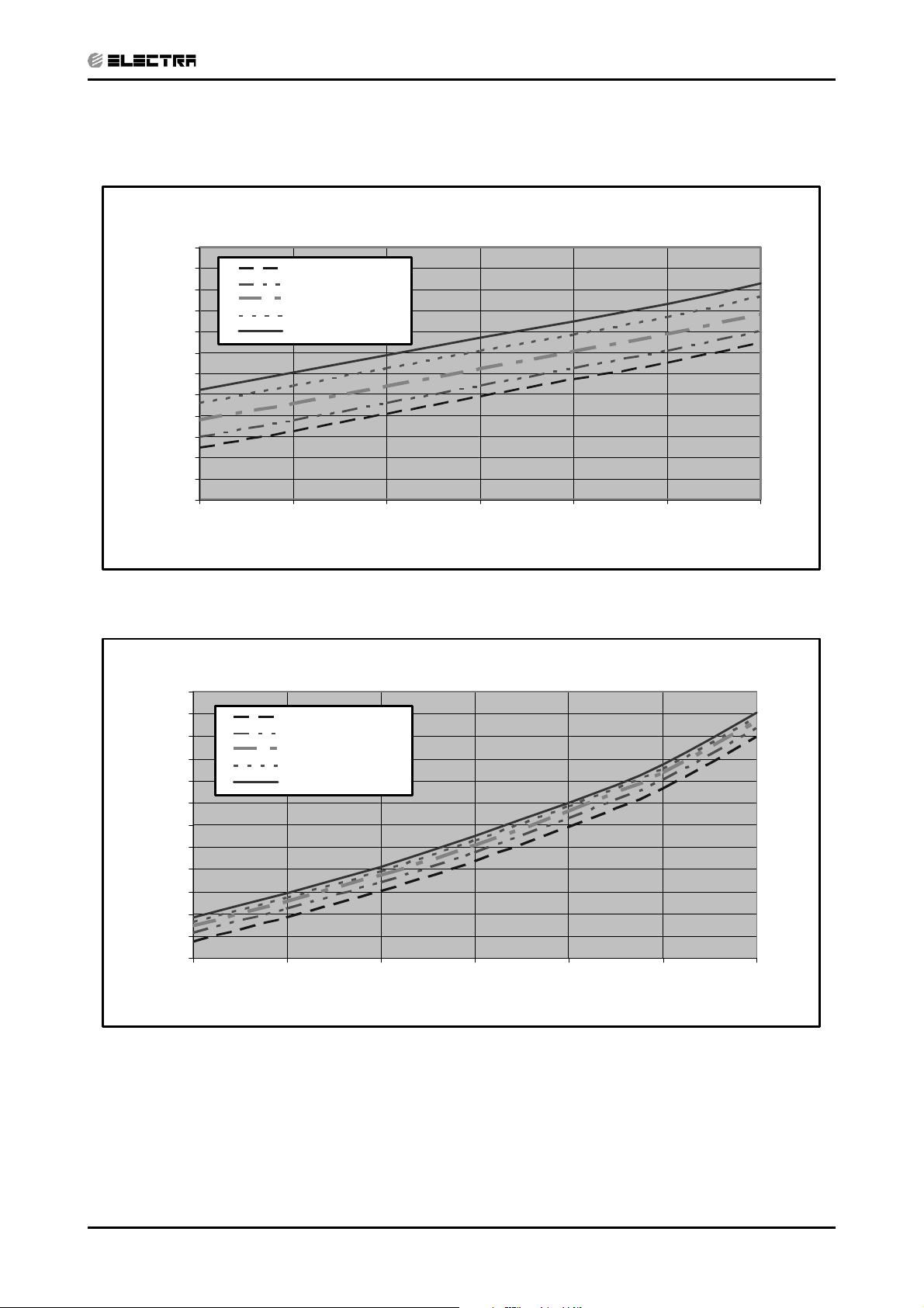
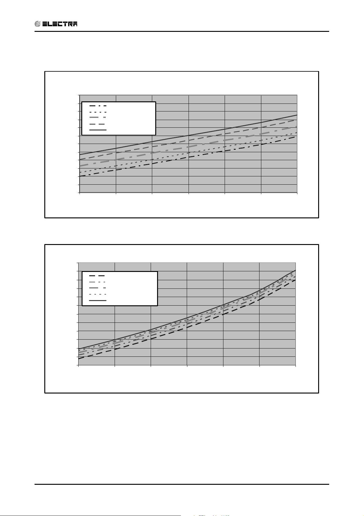
5.3.1 Cooling
Suction Pressure VS.Outdoor Temp
12.0
11.5
11.0
10.5
10.0
9.5
9.0
8.5
8.0
7.5
7.0
Suction Pressure (Bar[g])
6.5
6.0
15 20 25 30 35 40 46
21/15(DB/WB ºC)
24/17(DB/WB ºC)
27/19(DB/WB ºC)
29/21(DB/WB ºC)
32/23(DB/WB ºC)
PERFORMANCE DATA & PRESSURE CURVES
Outdoor Temp.(DB oC )
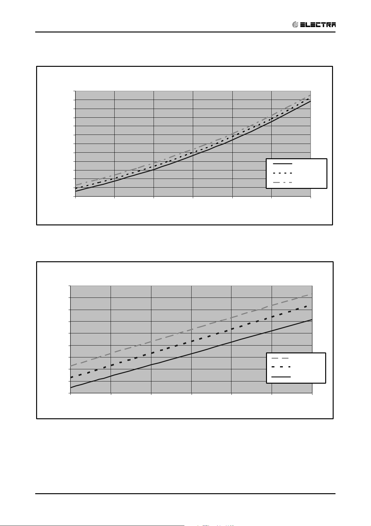
Discharge Pressure VS.Outdoor Temp
40
38
36
34
32
30
28
26
24
22
20
18
Discharge Pressure (Bar[g])
16
15 20 25 30 35 40 46
21/15(DB/WB ºC)
24/17(DB/WB ºC)
27/19(DB/WB ºC)
29/21(DB/WB ºC)
32/23(DB/WB ºC)
Outdoor Temp.(DB oC )
Revision Y05-01Service Manual - DNG Series
5-3
PERFORMANCE DATA & PRESSURE CURVES
CONTENT
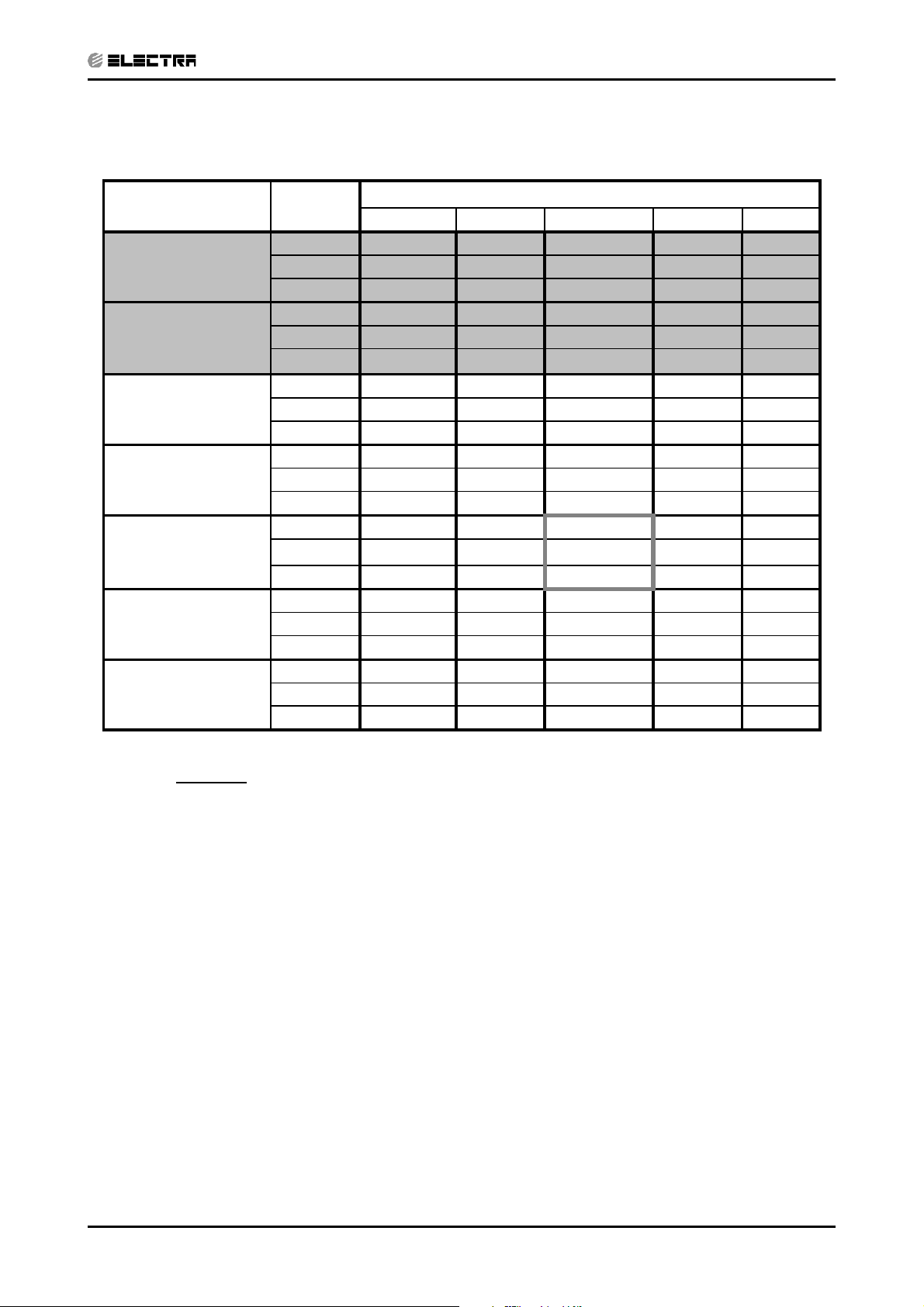
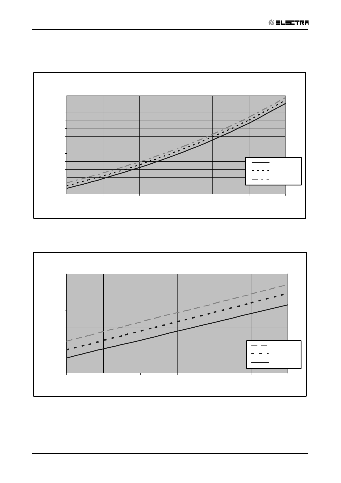
5.3.2 Heating
Suction Pressure VS.Outdoor Temp'
10.0
9.5
9.0
8.5
8.0
7.5
7.0
6.5
6.0
5.5
5.0
Suction Pressure(Bar[g])
4.5
4.0
-10 -5 0 5 10 15 20
15 DB (ºC)
20 DB (ºC)
25 DB (ºC)
Outdoor Temp.( WB oC )
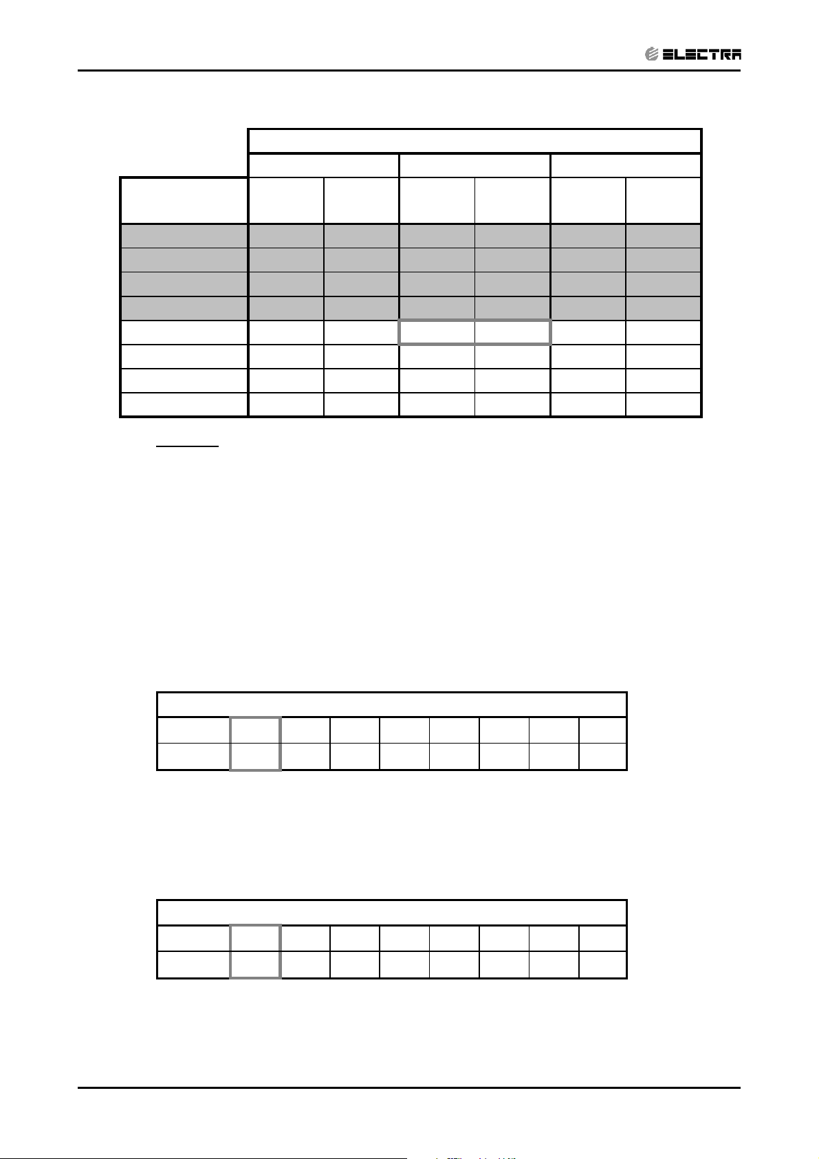
Discharge Pressure VS.Outdoor Temp'
38
36
34
32
30
28
26
24
22
Discharge Pressure(Bar[g])
20
-10 -5 0 5 10 15 20
Outdoor Temp.( WB oC )
25 DB (ºC)
20 DB (ºC)
15 DB (ºC)
5-4
Revision Y05-01 Service Manual - DNG Series
PERFORMANCE DATA & PRESSURE CURVES
CONTENT
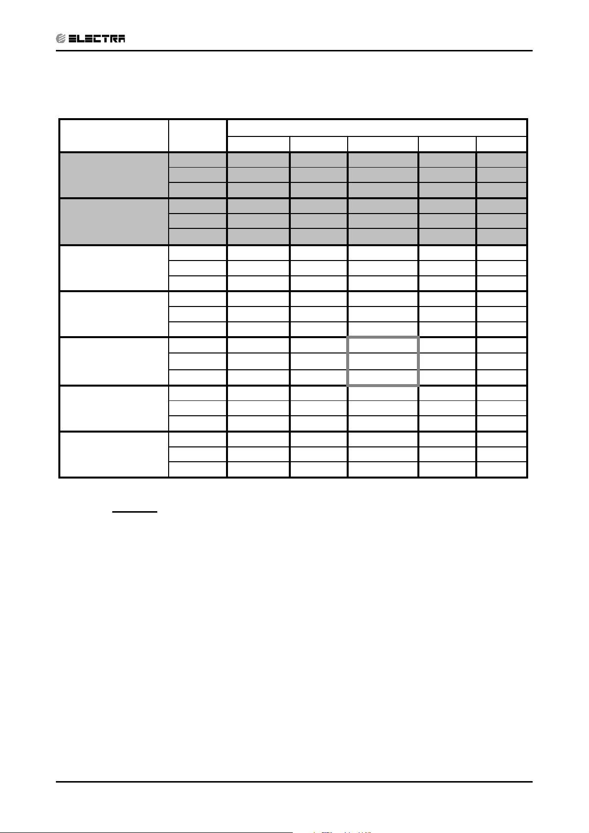
5.4 DNG 24, OU7- 24 1PH / 3PH
5.4.1 Cooling Capacity (kW)
Entering Air DB
OD Coil(
o
C)
15 SC
20 SC
25 SC
30 SC
35 SC
40 SC
46 SC
Data
TC
PL
TC
PL
TC
PL
TC
PL
TC
PL
TC
PL
TC
PL
Entering Air WB/DB ID Coil(oC)
15/21 17/24 19/27 21/29 23/32
7.04 7.45 7.80 8.14 8.42
5.17 5.48 5.78 5.64 5.74
1.70 1.71 1.71 1.72 1.72
6.97 7.38 7.73 8.07 8.35
4.97 5.28 5.58 5.42 5.54
1.84 1.85 1.86 1.87 1.88
6.69 7.18 7.59 7.94 8.21
5.03 5.38 5.69 5.59 5.73
1.99 2.00 2.02 2.04 2.04
6.28 6.76 7.31 7.59 7.87
4.78 5.16 5.57 5.46 5.68
2.15 2.18 2.21 2.22 2.23
5.80 6.28
4.50 4.89
2.33 2.36
6.90
5.35
2.40
7.25 7.52
5.29 5.50
2.42 2.43
5.24 5.73 6.35 6.69 6.97
4.18 4.60 5.06 4.98 5.22
2.51 2.54 2.59 2.62 2.64
4.55 5.04 5.66 6.00 6.28
3.80 4.21 4.74 4.65 4.87
2.75 2.79 2.84 2.88 2.91
LEGEND
TC – Total Cooling Capacity, kW
SC – Sensible Capacity, kW
PI – Power Input, kW
WB – Wet Bulb Temp., (oC)
DB – Dry Bulb Temp., (
ID – Indoor
OD – Outdoor
o
C)
Revision Y05-01Service Manual - DNG Series
5-5
PERFORMANCE DATA & PRESSURE CURVES
CONTENT
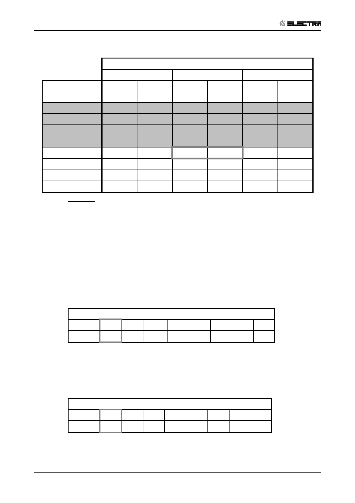
5.4.2 Heating
ENTERING AIR DB ID COIL(Oc)
15 20 25
ENTERING WB
OD COIL(
LEGEND
TH – Total Heating Capacity, kW
PI – Power Input, kW
WB – Wet Bulb Temp., (oC)
DB – Dry Bulb Temp., (oC)
ID – Indoor
OD – Outdoor
o
C)
-10 4.04 1.84 3.89 1.96 3.73 2.06
-7 4.35 1.89 4.20 1.99 4.04 2.10
-2 4.62 1.91 4.47 2.02 4.31 2.14
2 5.62 2.00 5.39 2.13 5.16 2.25
67.212.15
10 7.84 2.27 7.63 2.43 7.42 2.59
15 8.47 2.37 8.26 2.55 8.05 2.71
20 8.93 2.44 8.72 2.65 8.47 2.85
TH Pl TH Pl TH Pl
7.00 2.30
6.76 2.44
5.5 Capacity Correction Factor Due to Tubing Length
5.5.1 Cooling
TOTAL TUBING LENGTH (One Way)
3m
1.01
7.5m
10m 15m 20m 25m 30m 40m 50m
1
0.98 0.97 0.96 0.95 0.94 0.93 0.9
* Minimum recommended tubing length between indoor and outdoor units is 3m.
5.5.2 Heating
TOTAL TUBING LENGTH (One Way)
3m
1.02
7.5m
10m 15m 20m 25m 30m 40m 50m
1
0.99 0.99 0.98 0.97 0.97 0.96 0.95
* Minimum recommended tubing length between indoor and outdoor units is 3m.
5-6
Revision Y05-01 Service Manual - DNG Series
5.6 Pressure Curves
CONTENT
5.6.1 Cooling
Suction Pressure VS.Outdoor Temp
12.0
11.5
11.0
10.5
10.0
9.5
9.0
8.5
8.0
7.5
7.0
Suction Pressure (Bar[g])
6.5
6.0
15 20 25 30 35 40 46
21/15(DB/WB ºC)
24/17(DB/WB ºC)
27/19(DB/WB ºC)
29/21(DB/WB ºC)
32/23(DB/WB ºC)
PERFORMANCE DATA & PRESSURE CURVES
Outdoor Temp.(DB oC )
Discharge Pressure VS.Outdoor Temp
40
38
36
34
32
30
28
26
24
22
20
18
Discharge Pressure (Bar[g])
16
15 20 25 30 35 40 46
21/15(DB/WB ºC)
24/17(DB/WB ºC)
27/19(DB/WB ºC)
29/21(DB/WB ºC)
32/23(DB/WB ºC)
Outdoor Temp.(DB oC )
Revision Y05-01Service Manual - DNG Series
5-7
PERFORMANCE DATA & PRESSURE CURVES
CONTENT
5.6.2 Heating
Suction Pressure VS.Outdoor Temp
10.0
9.5
9.0
8.5
8.0
7.5
7.0
6.5
6.0
5.5
5.0
Suction Pressure(Bar[g])
4.5
4.0
-10 -5 0 5 10 15 20
Outdoor Temp.( WB oC )
15 DB (ºC)
20 DB (ºC)
25 DB (ºC)
Discharge Pressure VS.Outdoor Temp
40
38
36
34
32
30
28
26
24
22
20
Discharge Pressure(Bar[g])
18
-10 -5 0 5 10 15 20
Outdoor Temp.( WB oC )
25 DB (ºC)
20 DB (ºC)
15 DB (ºC)
5-8
Revision Y05-01 Service Manual - DNG Series
PERFORMANCE DATA & PRESSURE CURVES
CONTENT
5.7 DNG 30, OU8- 30 1PH / 3PH
5.7.1 Cooling Capacity (kW)
Entering Air DB
OD Coil(
o
C)
15 SC
20 SC
25 SC
30 SC
35 SC
40 SC
46 SC
Data
TC
PL
TC
PL
TC
PL
TC
PL
TC
PL
TC
PL
TC
PL
Entering Air WB/DB ID Coil(oC)
15/21 17/24 19/27 21/29 23/32
8.67 9.18 9.61 10.03 10.37
6.27 6.65 7.01 6.85 6.96
2.13 2.13 2.14 2.15 2.15
8.59 9.10 9.52 9.95 10.29
6.12 6.50 6.87 6.67 6.82
2.30 2.31 2.33 2.34 2.35
8.25 8.84 9.35 9.78 10.12
6.10 6.53 6.91 6.78 6.96
2.48 2.51 2.53 2.55 2.55
7.74 8.33 9.01 9.35 9.69
5.79 6.25 6.76 6.62 6.89
2.69 2.72 2.76 2.78 2.79
7.14 7.74
5.46 5.93
2.91 2.95
8.50
6.49
3.00
8.93 9.27
6.41 6.67
3.02 3.04
6.46 7.06 7.82 8.25 8.59
5.07 5.58 6.13 6.04 6.33
3.13 3.18 3.24 3.27 3.29
5.61 6.21 6.97 7.40 7.74
4.61 5.11 5.75 5.64 5.91
3.44 3.49 3.55 3.60 3.64
LEGEND
TC – Total Cooling Capacity, kW
SC – Sensible Capacity, kW
PI – Power Input, kW
WB – Wet Bulb Temp., (
DB – Dry Bulb Temp., (
ID – Indoor
OD – Outdoor
o
C)
o
C)
Revision Y05-01Service Manual - DNG Series
5-9
PERFORMANCE DATA & PRESSURE CURVES
CONTENT
5.7.2 Heating
ENTERING AIR DB ID COIL(Oc)
15 20 25
ENTERING WB
o
OD COIL(
C)
-10 5.20 2.24 5.00 2.39 4.80 2.51
-7 5.59 2.30 5.40 2.42 5.20 2.55
-2 5.94 2.32 5.74 2.46 5.54 2.60
2 7.23 2.44 6.93 2.59 6.63 2.74
6 9.27 2.62
10 10.08 2.76 9.81 2.95 9.54 3.16
15 10.89 2.88 10.62 3.11 10.35 3.30
20 11.48 2.97 11.21 3.22 10.89 3.47
LEGEND
TH – Total Heating Capacity, kW
PI – Power Input, kW
WB – Wet Bulb Temp., (oC)
DB – Dry Bulb Temp., (oC)
ID – Indoor
OD – Outdoor
TH Pl TH Pl TH Pl
9.00 2.80
8.69 2.97
5.8 Capacity Correction Factor Due to Tubing Length
5.8.1 Cooling
TOTAL TUBING LENGTH (One Way)
3m
1.01
7.5m
10m 15m 20m 25m 30m 40m 50m
1
0.98 0.97 0.96 0.95 0.94 0.93 0.9
* Minimum recommended tubing length between indoor and outdoor units is 3m.
5.8.2 Heating
TOTAL TUBING LENGTH (One Way)
3m
1.02
7.5m
10m 15m 20m 25m 30m 40m 50m
1
0.99 0.99 0.98 0.97 0.97 0.96 0.95
* Minimum recommended tubing length between indoor and outdoor units is 3m.
5-10
Revision Y05-01 Service Manual - DNG Series
5.9 Pressure Curves
CONTENT
5.9.1 Cooling
Suction Pressure VS.Outdoor Temp'
12.0
11.5
11.0
10.5
10.0
9.5
9.0
8.5
8.0
7.5
7.0
Suction Pressure (Bar[g])
6.5
6.0
15 20 25 30 35 40 46
21/15(DB/WB ºC)
24/17(DB/WB ºC)
27/19(DB/WB ºC)
29/21(DB/WB ºC)
32/23(DB/WB ºC)
PERFORMANCE DATA & PRESSURE CURVES
Outdoor Temp.(DB oC )
Discharge Pressure VS.Outdoor Temp'
40
38
36
34
32
30
28
26
24
22
20
18
Discharge Pressure (Bar[g])
16
15 20 25 30 35 40 46
21/15(DB/WB ºC)
24/17(DB/WB ºC)
27/19(DB/WB ºC)
29/21(DB/WB ºC)
32/23(DB/WB ºC)
Outdoor Temp.(DB oC )
Revision Y05-01Service Manual - DNG Series
5-11
 Loading...