

Page 1

Service Manual
CONTENT
Alpha / Delta Series
Indoor Units Outdoor Units
Alpha 7 CON 7 (Alpha)
Delta 7 GCN 7
Alpha 9 GCN 9 (Alpha)
Delta 9 DF
Alpha 12 GCN 12 (Alpha)
Delta 12 DF
Alpha 17 ONG3-14 B1
Alpha 17 ONG3-17 (Alpha)
Delta 17 DF ONG3-17
Delta 24 OU7-24C
ONG3-9 B1
ONG3-9 B2
ONG3-12 B1
ONG3-12 B2
SM ALPHA 1-E.3 GB
REFRIGERANT
R410A
COOLING ONLY
HEAT PUMP
JULY 2008
Page 2
LIST OF EFFECTIVE PAGES
CONTENT
LIST OF EFFECTIVE PAGES
Note: Changes in the pages are indicated by a “Revision#” in the footer of each effected page
(when none indicates no changes in the relevant page). All pages in the following list represent
effected/ non effected pages divided by chapters.
Dates of issue for original and changed pages are:
Original ....... 0 ........ 10 December 2004
Total number of pages in this publication is 169 consisting of the following:
Page
No.
Title ....................... 3
A ........................... 3
i ............................. 3
1-1 - 1-2 ................ 3
2-1 - 2-13 .............. 3
3-1 ........................ 3
4-1 - 4-6 ................ 3
5-1 - 5-40 .............. 3
6-1 - 6-8 ................ 3
7-1 ........................ 3
8-1 - 8-5 ................ 3
9-1 ........................ 3
10-1-10-4 .............. 3
11-1 ....................... 3
12-1-12-32 ............ 3
13-1-13-2 .............. 3
14-1-14-49 ............ 3
Appendix -A ...........3
Revision
No. #
Page
No.
Revision
No. #
Page
No.
Revision
No. #
• Zero in this column indicates an original page.
*Due to constant improvements please note that the data on this service manual can be modifi ed with out notice.
**Photos are not contractual
A
SM ALPHA 1-E.3 GB
Page 3

TABLE OF CONTENTS
Table of Contents
1. INTRODUCTION ...................................................................................................1-1
2. PRODUCT DATA SHEET ......................................................................................2-1
3. RATING CONDITIONS ..........................................................................................3-1
4. OUTLINE DIMENSIONS .......................................................................................4-1
5. PERFORMANCE DATA & PRESSURE CURVES ................................................5-1
6. SOUND LEVEL CHARACTERISTICS ..................................................................6-1
7. ELECTRICAL DATA ..............................................................................................7-1
8. WIRING DIAGRAMS .............................................................................................8-1
9. ELECTRICAL CONNECTIONS .............................................................................9-1
10. REFRIGERATION DIAGRAMS .............................................................................10-1
11. TUBING CONNECTIONS ......................................................................................11-1
12. CONTROL SYSTEM .............................................................................................12-1
13. TROUBLESHOOTING ..........................................................................................13-1
14. EXPLODED VIEWS AND SPARE PARTS LISTS .................................................14-1
15. APPENDIX A .........................................................................................................15-1
SM ALPHA 1-E.3 GB
i
Page 4

1. INTRODUCTION
CONTENT
1.1 General
The new Alpha / Delta split wall mounted is based on the compact range. It comprise
the ST (cooling only) and RC (heat pump) models,
The indoor Alpha / Delta units are available as LED display types, featuring esthetic
design, compact dimensions, and low noise operation.
1.2 Main Features
The Alpha / Deltaseries benefi ts from the most advanced technological innovations,
namely:
● R410A models
● Microprocessor control.
● Infrared remote control with liquid crystal display.
● Indoor large diameter cross fl ow fan, allowing low noise level operation.
INTRODUCTION
● Bended indoor coil with treated aluminum fi ns and coating for improved
effi ciency.
● High COP.
● Easy access to the interconnecting tubing and wiring connections, so that
removing the front grill or casing is not necessary.
● Refrigerant pipes can be connected to the indoor unit from 5 different optional
directions.
● Automatic treated air sweep.
● Easy installation and service.
● 4M length tubing connection kit is provided in the outdoor unit (optional).
1.3 Indoor Unit
The indoor unit is wall mounted, and can be easily fi tted to many types of residential
and commercials applications.
It includes:
● Casing with air inlet and outlet grills.
● A large-diameter tangential fan.
SM ALPHA 1-E.3 GB
● Bended coil with treated aluminum fi ns.
● Motorized fl aps
● Multi-speed motor with internal protection
● Advanced electronic control box assembly
● Interconnecting wiring terminal block
● Mounting plate
1-1
Page 5

INTRODUCTION
CONTENT
1.4 Filtration
The Alpha / Delta series presents several types of air fi lters
● Easily accessible, and re-usable pre-fi lters (mesh)
● Pre-charged electrostatic fi lter (optional)
● Active carbon fi lter (optional)
1.5 Control
The microprocessor indoor controller, and an infrared remote control, supplied as
standard, provide complete operating function and programming. For further details
please refer to the Operation Manual, Appendix A.
1.6 Outdoor Unit
The Alpha / Delta outdoor units can be installed as fl oor or wall mounted units by using
a wall supporting bracket. The metal sheets are protected by anti- corrosion paint work
allowing long life resistance. All outdoor units are pre-charged. For further information
please refer to the Product Data Sheet, Chapter 2.
It includes :
● A Rotary compressor mounted in a soundproofed compartment :
● Axial fan.
● Outdoor coil with hydrophilic louver fi ns for RC units.
● Outlet air fan grill.
● Service valves” fl are” type connection.
● Interconnecting wiring terminal block.
1.7 Tubing Connections
Flare type interconnecting tubing can be produced on site.
A connection pipe kit is provided in outdoor package.
For further details please refer to the Installation Manual, Appendix A.
1.8 Accessories
ASK (All Season Kit):
For low ambient working conditions in cooling, an ASK can be installed inside the outdoor
unit. This kit allows cooling operation down to outdoor temp of -10 ºC by gradually
controlling the outdoor fan speed motor.
1.9 Inbox Documentation
1-2
Each unit is supplied with its own installation and operation manuals.
SM ALPHA 1-E.3 GB
Page 6
PRODUCT DATA SHEET
CONTENT
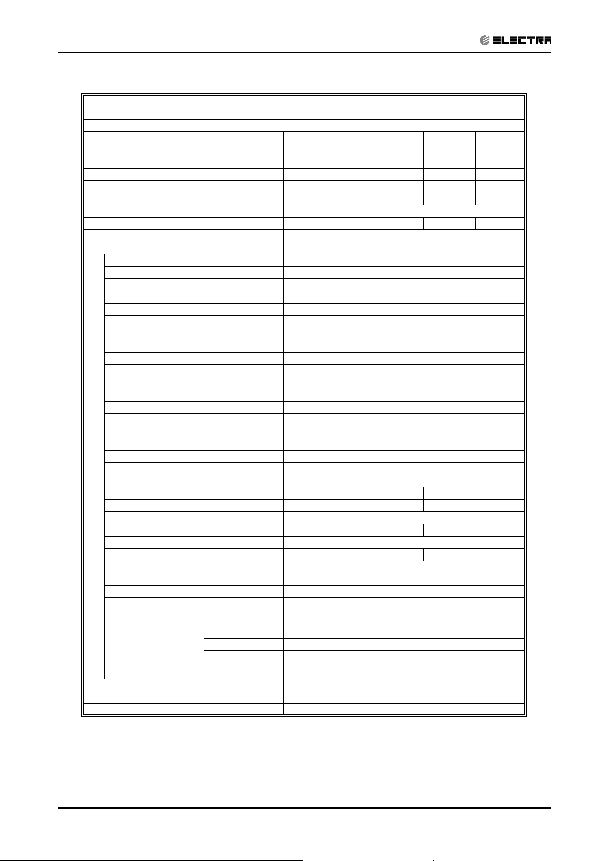
2. PRODUCT DATA SHEET
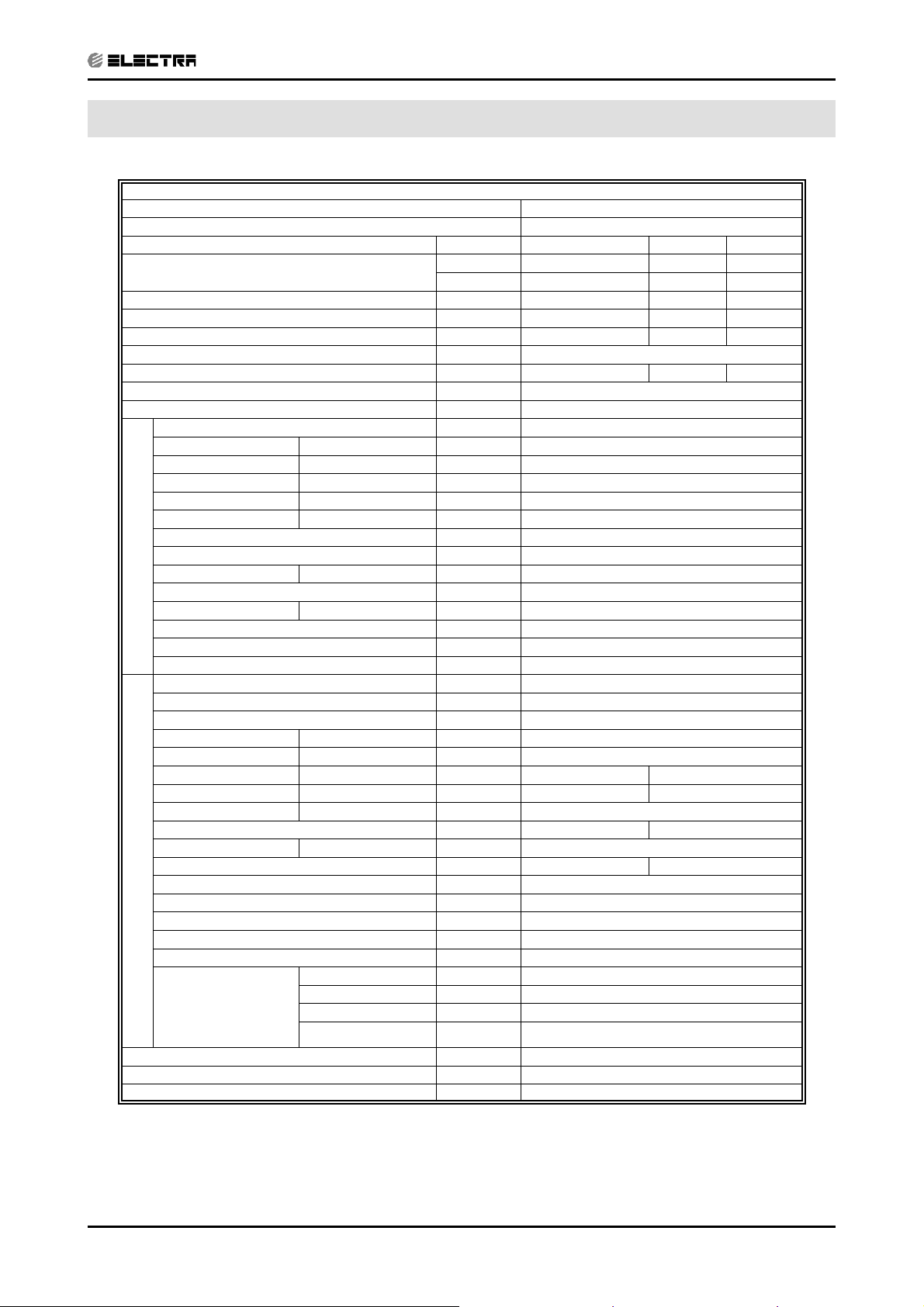
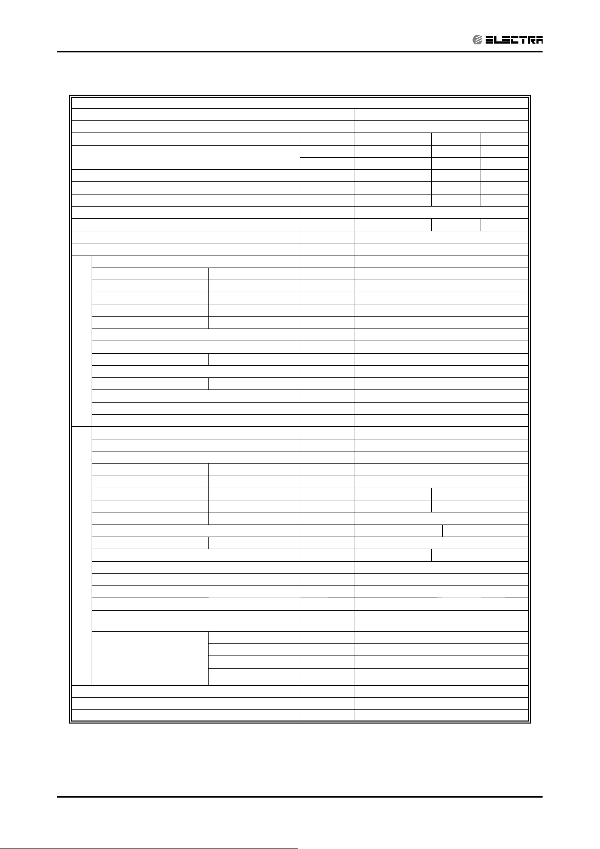
2.1 Alpha 7 / CON7 (Alpha)
Model Indoor Unit Alpha 7
Model Outdoor Unit CON 7 (Alpha)
Installation Method of Pipe Flared
Characteristics Units Cooling Only Cooling Heating
Capacity
Power input
EER (Cooling) or COP(Heating)
Energy effi ciency class B B B
Power supply V/Ph/Hz 230V/Single/50Hz
Rated current A 3.0 3.0 2.8
Starting current A 15
Circuit breaker rating A 10
Operation control type Remote control
Heating elements kW
Others
(1)
(1)
(1)
Fan type & quantity Crossfl ow x 1
Fan speeds H/M/L RPM 1150/950
(2)
Air fl ow
External static pressure Min-Max Pa 0
Sound power level
Sound pressure level
Moisture removal l/hr 0.8
Condenstate drain tube I.D mm 16
INDOOR
Dimensions WxHxD mm 680*250*180
Weight kg 7
Package dimensions WxHxD mm 740*250*310
Packaged weight kg 9.5
Units per pallet units 36
Stacking height units 9 levels
Refrigerant control Capillary tube
Compressor type, model Rotary,TOSHIBA,PA82X1C-4DZDE
Fan type & quantity Propeller(direct) x 1
Fan speeds H/L RPM 850
Air fl ow H/L m3/hr 1200
Sound power level H/L dB(A) 61 62
Sound pressure level
Dimensions WxHxD mm 610*235*490
Weight kg 27 27.5
Package dimensions WxHxD mm 720*550*360
Packaged weight kg 30/33.5(with kit) 30.5/34(with kit)
Units per pallet Units 12
OUTDOOR
Stacking height units 4 levels
Refrigerant type R410A
Refrigerant chargless distance Kg/m 0.72kg/7.5m
Additional charge kg 4m≤length≤10m,0.72kg; 10m<length≤15m,0.8kg
Connections between
units
(3)
(4)
(4)
H/M/L m3/hr 390/320
H/M/L dB(A) 50/44
H/M/L dB(A) 37/32
H/L dB(A) 52 53
Liquid line In.(mm) Ф 1/4”(6.35)
Suction line In.(mm) Ф 3/8”(9.53)
Max.tubing length m. Max.15
Max.height difference m. Max.7
Btu/hr 7000 7000 7300
kW 2.05 2.05 2.15
kW 0.68 0.68 0.63
W/W 3.01 3.01 3.41
(1) Rating conditions in accordance with ISO 5151 and ISO 13253 (for ducted units) and EN 14511.
(2) Airfl ow in ducted units; at nominal external static pressure.
(3) Sound power in ducted units is measured at air discharge.
(4) Sound pressure level measured at 1 meter distance from unit.
SM ALPHA 1-E.3 GB
2-1
Page 7

PRODUCT DATA SHEET
CONTENT
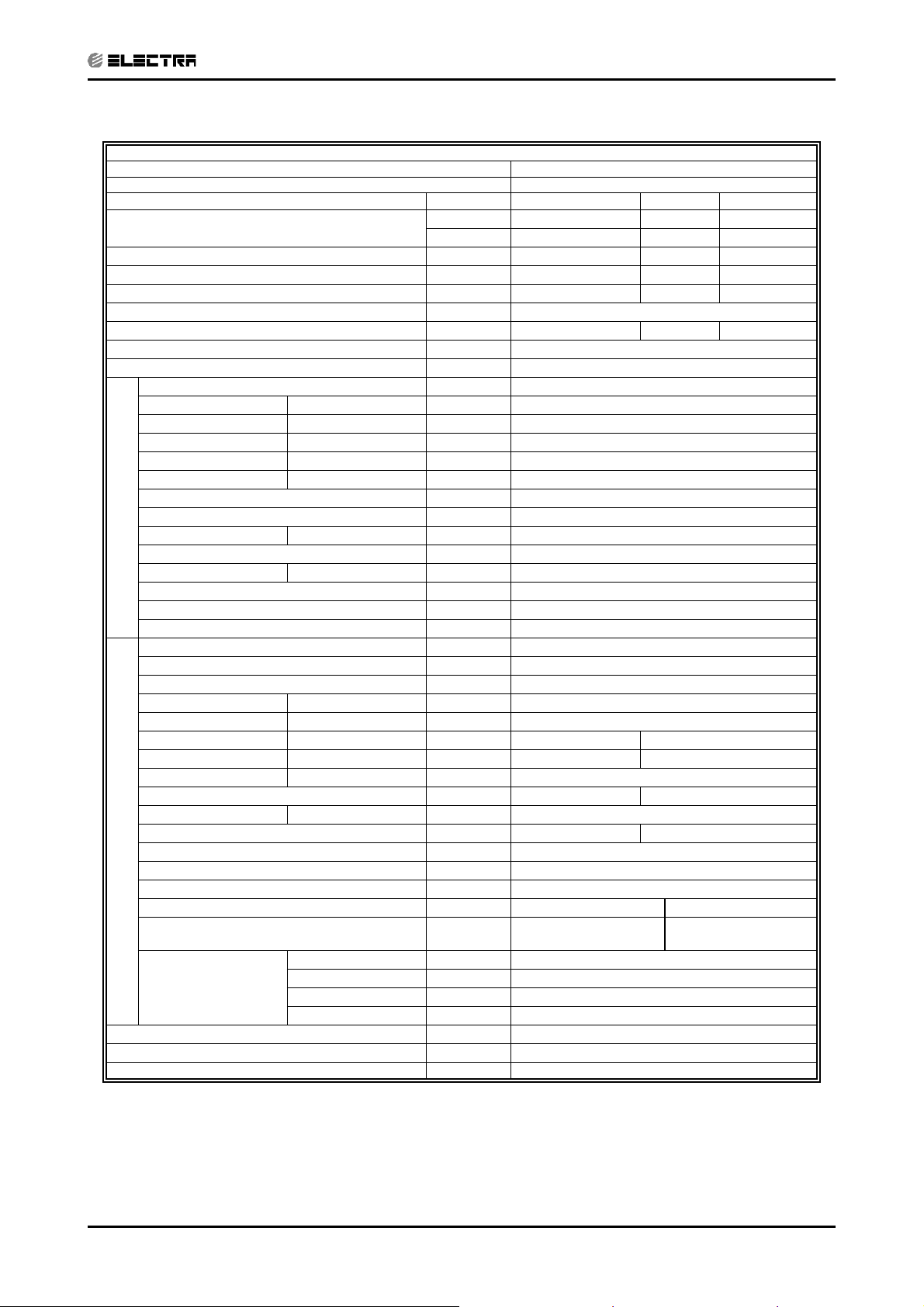
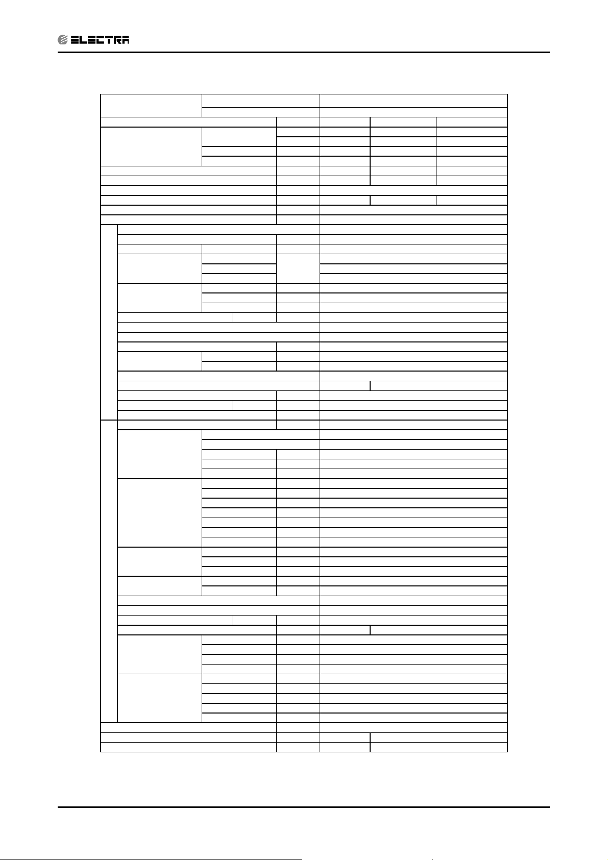
2.2 Delta 7 R410A А2 DF / GCN 7 RC R410A A2
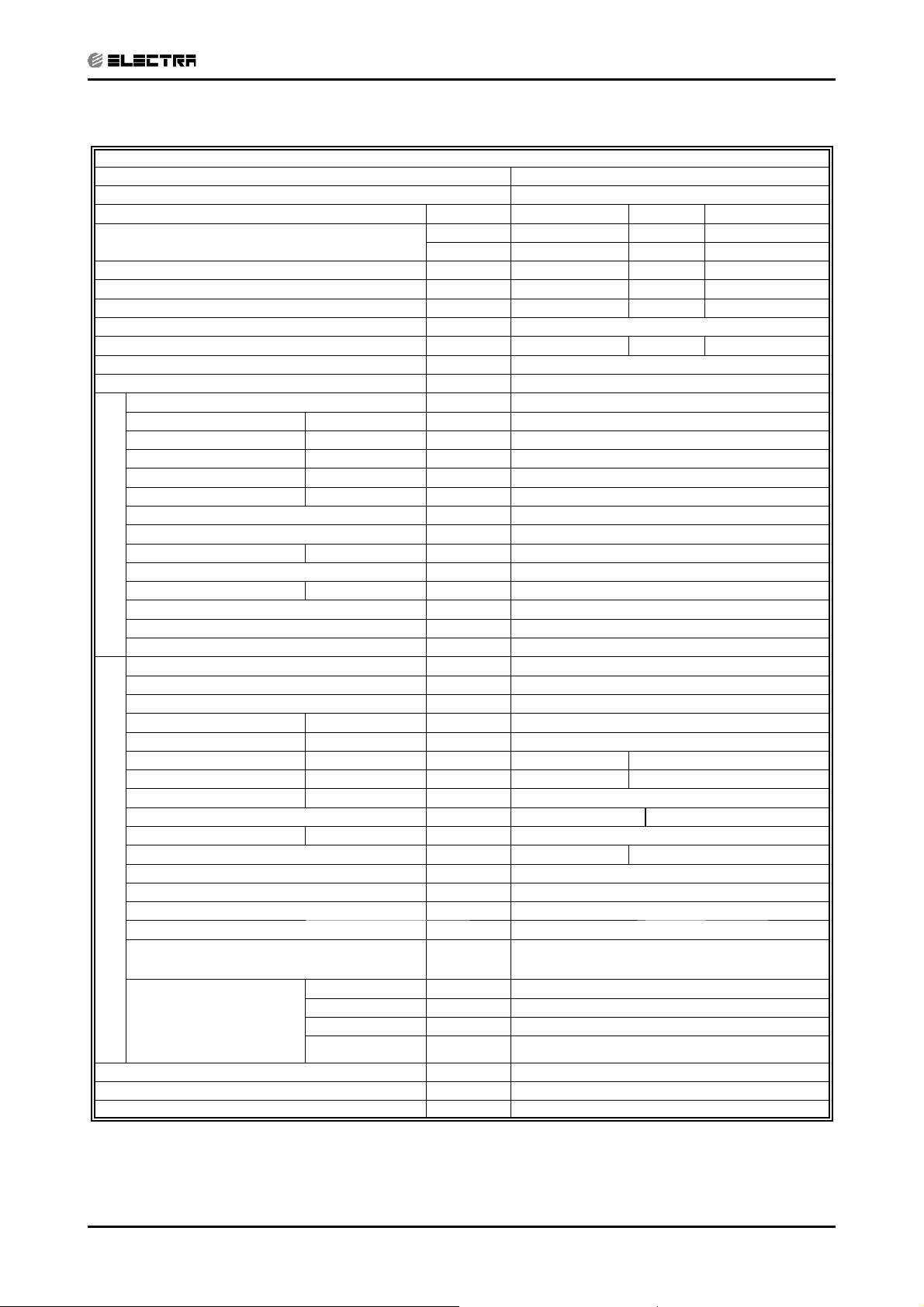
Model Indoor Unit Delta 7 R410A A2 DF
Model Outdoor Unit GCN 7 RC R410A A2
Installation Method of Pipe Flared
Characteristics Units Cooling Heating
Capacity (4)
Power input (4) kW 0.62 0.67
EER (Cooling) or COP(Heating) (4) W/W 3.70 3.45
Energy effi ciency class(SII) A A
Power supply
Rated current A 2.8 3.0
Power factor
Prated (IDU)
Prated (IDU+ODU)
Starting current A 15
Circuit breaker rating A 10
Fan type & quantity Crossfl ow x 1
Fan speeds H/M/L RPM 1050/-/900
Air fl ow (1) H/M/L m3/hr 450/-/380
External static pressure Min Pa 0
Sound power level (2) H/M/L dB(A) 50/-/44
Sound pressure level(3) H/M/L dB(A) 37/-/31
Moisture removal l/hr 0.74
Condenstate drain tube I.D mm 16
INDOOR
Dimensions WxHxD mm 680x250x180
Net Weight kg 6
Package dimensions WxHxD mm 740x310x248
Packaged weight kg 8.5
Units per pallet units 32
Stacking height units 8 levels
Refrigerant control Capillary tube
Compressor type,model Rotary,Toshiba(GMCC),PA82X1C-4DZDE
Fan type & quantity Propeller(direct) x 1
Fan speeds H RPM 830
Air fl ow H m3/hr 1450
Sound power level H dB(A) 60
Sound pressure level(3) H dB(A) 50
Dimensions WxHxD mm 830x545x245
Net Weight kg 31.5
Package dimensions WxHxD mm 870x600x320
Packaged weight kg 34
Units per pallet Units 12
OUTDOOR
Stacking height units 3 levels
Refrigerant type R410A
Refrigerant chargless distance kg(7.5m) 0.8kg
Additional charge 4m≤Length≤10m: +0g; 10mLength≤15m: +50g
Liquid line In.(mm) 1/4"(6.35)
Connections between
units
Operation control type Remote control
Heating elements(Option) kW
Others
Suction line In.(mm) 3/8"(9.53)
Max.tubing length m. Max.15
Max.height
difference
Btu/hr 7780 7850
kW 2.28 2.30
V 230
Ph 1
Hz 50
0.95 0.95
W 30
W 890
m. Max.7
(1) Rating conditions in accordance with ISO 5151 and ISO 13253 (for ducted units) and EN 14511.
(2) Airfl ow in ducted units; at nominal external static pressure.
(3) Sound power in ducted units is measured at air discharge.
(4) Sound pressure level measured at 1 meter distance from unit.
2-2
SM ALPHA 1-E.3 GB
Page 8
PRODUCT DATA SHEET
CONTENT
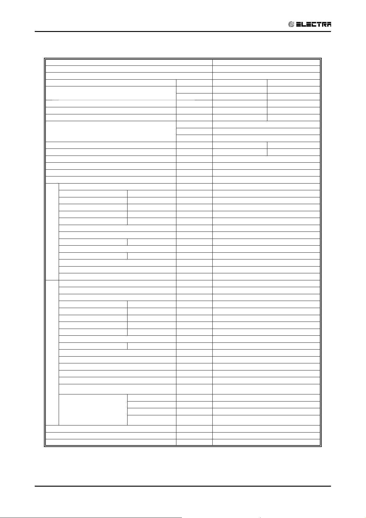
2.3 Alpha 9 / GCN9 (Alpha)
Model Indoor Unit Alpha 9
Model Outdoor Unit GCN 9 (Alpha)
Installation Method of Pipe Flared
Characteristics Units Cooling Only Cooling Heating
Capacity
Power input
EER (Cooling) or COP(Heating)
Energy effi ciency class
Power supply V/Ph/Hz 230V/Single/50Hz
Rated current A 3.9 3.9 4.1
Starting current A 21.7
Circuit breaker rating A 10
Operation control type Remote control
Heating elements kW
Others
(1)
(1)
(1)
Fan type & quantity Crossfl ow x 1
Fan speeds H/M/L RPM 1310/1100
(2)
Air fl ow
External static pressure Min-Max Pa 0
Sound power level
Sound pressure level
Moisture removal l/hr 1.2
Condenstate drain tube I.D mm 16
INDOOR
Dimensions WxHxD mm 680*250*180
Weight kg 7
Package dimensions WxHxD mm 740*250*310
Packaged weight kg 9.5
Units per pallet units 36
Stacking height units 9 levels
Refrigerant control Capillary tube
Compressor type,model
Fan type & quantity Propeller(direct) x 1
Fan speeds H/L RPM 750
Air fl ow H/L m3/hr 1370
Sound power level H/L dB(A) 59 61
Sound pressure level
Dimensions WxHxD mm
Weight kg 32.5 33.5
Package dimensions WxHxD mm 880x320x610
Packaged weight kg 35/38.5(with kit) 36/39.5(with kit)
Units per pallet Units 9
OUTDOOR
Stacking height units 3levels
Refrigerant type R410A
Refrigerant chargless distance kg/m 0.85kg/7.5m 0.9kg/7.5m
Additional charge kg
Connections between
units
(3)
(4)
(4)
H/M/L m3/hr 450/360
H/M/L dB(A) 53/49
H/M/L dB(A) 41/35
H/L dB(A) 49 51
Liquid line In.(mm) Ф 1/4”(6.35)
Suction line In.(mm) Ф 3/8”(9.53)
Max.tubing length m. Max.15
Max.height difference m. Max.7
Btu/hr
kW
kW
W/W
9000 9000 9650
2.64 2.64 2.83
0.87 0.87 0.93
3.03 3.03 3.04
B
BD
Rotary,TOSHIBA,PA108X1C-4FZDE
830x245x545
4m≤length≤10m,0.85kg
10m<length≤15m,0.93kg
4m≤length≤10m,0.9kg
10m<length≤15m,0.98kg
(1) Rating conditions in accordance with ISO 5151 and ISO 13253 (for ducted units). and EN 14511
(2) Airfl ow in ducted units; at nominal external static pressure.
(3) Sound power in ducted units is measured at air discharge.
(4) Sound pressure level measured at 1 meter distance from unit.
SM ALPHA 1-E.3 GB
2-3
Page 9
PRODUCT DATA SHEET
y
y
A
A
A
y
(A)dB(A)
g
y
y
(A)
)
g
g/mg
(mm)
)
)
CONTENT
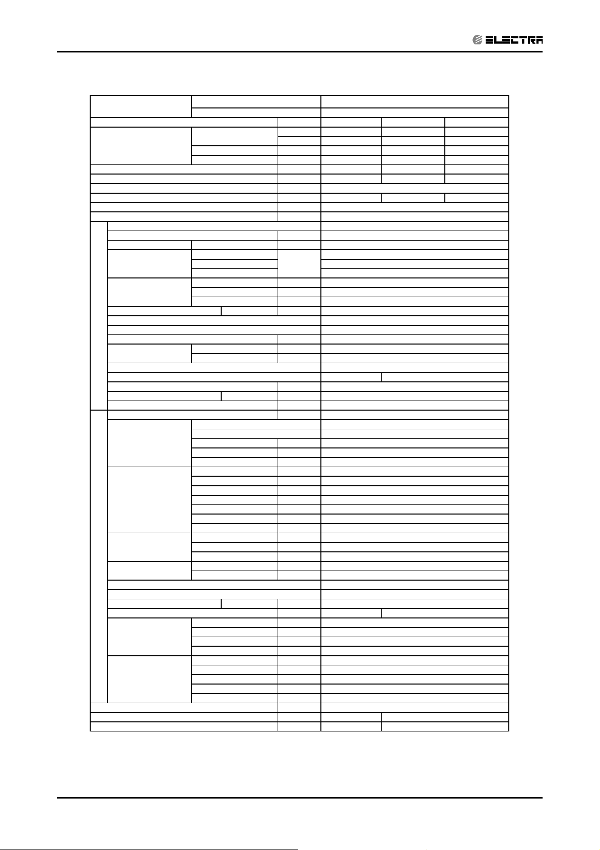
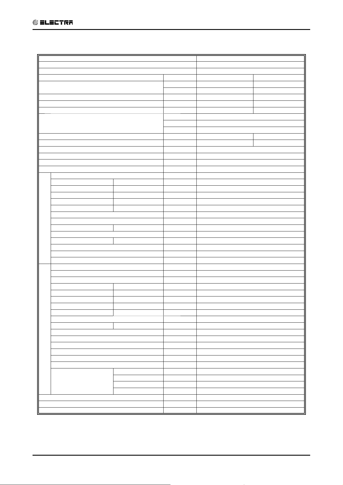
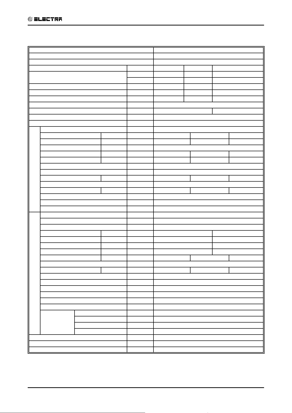
2.4 Delta 9 RC/ST fi xed RPM R410A / ONG3-9 R410A B1
Model
Characteristics Cooling
Capacity (4)
Power input (4)
EER (Cooling) or COP(Heating) (4) 3.34
Power supply 220-240V/Single/50Hz
Running Current (Rated) 3.5
Starting current
Circuit breaker rating
Model
Fan type & quantity
Fan speeds RPM
Air flow (1)
Coil
External static pressure Nom Pa
Airflow direction control
INDOOR
Air Filter
Running Current (Rated)
Sound
Cooling Temperature Operating Range (Min/Max)
Heating Temperature Operating Range (Min/Max)
Condenstate drain tube I.D
Dimensions/(packaged)
Weight
Model
Compressor
Fan
Coil
Sound
OUTDOOR
Cooling Temperature Operating Range (Min/Max)
Heating Temperature Operating Range (Min/Max)
Dimensions/(packaged)
Weight(packaged)
Refrigerant
Connections between
units
Operation control type
Heating elements (Option) Others -
Indoor unit
Outdoor unit
Total
Sensible capacit
Moisture removal l/hr 0.98
H/M/L
H
M
L
Rows
Fin Spacing 1.5
Power level (H/M/L)
Pressure level(3) (H/M/L
WxDxH mm
Type
Model
Motor kW
Running Current (Rated
Motor Speed
Type
Blades
Diameter
Air flow
Motor Type
Speed (H/L)
Motor output
Area
Rows
Fin Spacing
Power level (H/L)
Pressure level(3) (H/L)
WxDxH mm
Type
Control
Chargless distance
Add charge per mtr
Liquid line
Suction line
Type
Max.tubing length
Max.height difference
Units Cooling Onl
Btu/hr 8870
kW 2.6
kW 1940
kW 0.78
W/W 3.34
V/Ph/Hz
L/S -
2
M
Qt
mm
amp
dB
mm
k
watt
amp
RPM
Qt
mm
m3/hr
RPM
watt
2
M
Qt
mm
dB
dB(A
k
k
/m
In.
In.(mm
m.
m.
kW -
Delta 9RC/ST fixed rpm R410A
ONG3-9 R410A B1
8870
2.6
1940
0.98
0.78
3.5
Delta 9RC/ST fixed rpm R410A
21°C DB (15 °C WB) / 32°C DB (23°C WB)
-
680*250*180 / 740*310*248
795*610*290 / 970*650*394
32 / 34.5
4m<L≤10m: +0g; 10m<L≤15m: +80g
-
21.7
10
Centifugal x1
1310/-/1100
125
100
0.126Area
2
0
-
supplied by others
0.13
53/-/49
41/-/35
10°C /27°C
16
9.5
ONG3-9 R410A B1
Single Rotary
PA103X1C-4DZDE
840/870
3.90/3.80
3000
Propeller(direct) x 1
3
400
1750
fixed RPM
730
20
0.45
2
1.5
60 / 49 / -
21°C/ 46°C
-9°C / 24°C
33 / 35.5
R410A
Capillary tube
0.91kg/7.5m
1/4"(6.35)
3/8"(9.53)
Flared
Max15
Max.8
RC7 Remote control
Heating
9720
2.85
-
-
0.850
3.35
3.8
(1) Airfl ow in ducted units;at nominal external static pressure.
(2)
Sound power in ducted units is measured at air discharge.
(3)
Sound pressure level measured at 1-meter distance from unit.
(4)
Rating conditions in accordance to AS 3823, ISO 5151 and ISO 13253 (for ducted units).
2-4
SM ALPHA 1-E.3 GB
Page 10

PRODUCT DATA SHEET
CONTENT
2.5 Delta 9 R410A B2 DF / ONG3-9 RC R410A B2 ISR
Model Indoor Unit Delta 9 R410A B2 DF ISR
Model Outdoor Unit ONG3-9 RC R410A B2 ISR
Installation Method of Pipe Flared
Characteristics Units Cooling Heating
Capacity (4)
Power input (4) kW 0.75 0.83
EER (Cooling) or COP(Heating) (4) W/W 3.60 3.50
Energy effi ciency class(SII) C C
Power supply
Rated current A 3.4 3.8
Power factor
Prated (IDU)
Prated (IDU+ODU)
Starting current A 16.6
Circuit breaker rating A 10
Fan type & quantity Crossfl ow x 1
Fan speeds H/M/L RPM 1320/-/1100
Air fl ow (1) H/M/L m3/hr 450/-/360
External static pressure Min Pa 0
Sound power level (2) H/M/L dB(A) 53/-/49
Sound pressure level(3) H/M/L dB(A) 41/-/35
Moisture removal l/hr 1.02
Condenstate drain tube I.D mm 16
INDOOR
Dimensions WxHxD mm 680x250x180
Net Weight kg 6
Package dimensions WxHxD mm 740x310x248
Packaged weight kg 8.5
Units per pallet units 32
Stacking height units 8 levels
Refrigerant control Capillary tube
Compressor type,model Rotary,Toshiba(GMCC),PA103X1C-4FZDE1
Fan type & quantity Propeller(direct) x 1
Fan speeds H RPM 780
Air fl ow H m3/hr 1800
Sound power level H dB(A) 59
Sound pressure level(3) H dB(A) 49
Dimensions WxHxD mm 795x610x290
Net Weight kg 33
Package dimensions WxHxD mm 970x650x394
Packaged weight kg 35.5
Units per pallet Units 9
OUTDOOR
Stacking height units 3 levels
Refrigerant type R410A
Refrigerant chargless distance kg(7.5m) 0.95kg
Additional charge 4m≤Length≤10m: +0g; 10m≤Length≤15m: +50g
Liquid line In.(mm) 1/4"(6.35)
Connections between
units
Operation control type Remote control
Heating elements(Option) kW
Others
Suction line In.(mm) 3/8"(9.53)
Max.tubing length m. Max.15
Max.height
difference
Btu/hr 9210 9890
kW 2.70 2.90
V 230
Ph 1
Hz 50
0.95 0.95
W 30
W 1050
m. Max.7
(1) Rating conditions in accordance with ISO 5151 and ISO 13253 (for ducted units) and EN 14511.
(2) Airfl ow in ducted units; at nominal external static pressure.
(3) Sound power in ducted units is measured at air discharge.
(4) Sound pressure level measured at 1 meter distance from unit.
SM ALPHA 1-E.3 GB
2-5
Page 11
PRODUCT DATA SHEET
CONTENT
2.6 Alpha 12 / GCN12 (Alpha)
Model Indoor Unit Alpha 12
Model Outdoor Unit GCN 12 (Alpha)
Installation Method of Pipe Flared
Characteristics Units Cooling Only Cooling Heating
Capacity
Power input
EER (Cooling) or COP(Heating)
Energy effi ciency class
Power supply V/Ph/Hz 230V/Single/50Hz
Rated current A 5.2 5.2 5.2
Starting current A 31.5
Circuit breaker rating A 10
Operation control type Remote control
Heating elements kW
Others
(1)
(1)
(1)
Fan type & quantity Crossfl ow x 1
Fan speeds H/M/L RPM 1210/950
(2)
Air fl ow
External static pressure Min-Max Pa 0
Sound power level
Sound pressure level
Moisture removal l/hr 1.5
Condenstate drain tube I.D mm 16
INDOOR
Dimensions WxHxD mm 840*250*180
Weight kg 8
Package dimensions WxHxD mm 900*250*310
Packaged weight kg 11
Units per pallet units 36
Stacking height units 9 levels
Refrigerant control Capillary tube
Compressor type,model Rotary,TOSHIBA,PA145X2C-4FT
Fan type & quantity Propeller(direct) x 1
Fan speeds H/L RPM 830
Air fl ow H/L m3/hr 1450
Sound power level H/L dB(A) 65 65
Sound pressure level
Dimensions WxHxD mm 830x245x545
Weight kg 37 38
Package dimensions WxHxD mm 880x320x610
Packaged weight kg 39.5/43(with kit) 40.5/44(with kit)
Units per pallet Units 9
OUTDOOR
Stacking height units 3 levels
Refrigerant type R410A
Refrigerant chargless distance kg/m 0.89kg/7.5m
Additional charge per 1 meter g/m
Connections between
units
(3)
(4)
(4)
H/M/L m3/hr 620/460
H/M/L dB(A) 53/47
H/M/L dB(A) 40/33
H/L dB(A) 54 54
Liquid line In.(mm) Ф1/4”(6.35)
Suction line In.(mm) ø3/8”(9.53)
Max.tubing length m. Max.15
Max.height
difference
Btu/hr
kW
kW
W/W
m. Max.7
12000 12000 12900
3.50 3.50 3.78
1.16 1.16 1.17
3.02 3.02 3.23
BBC
4m≤length≤10m,0.89kg
10m<length≤15m,0.97kg
(1) Rating conditions in accordance with ISO 5151 and ISO 13253 (for ducted units) and EN 14511.
(2) Airfl ow in ducted units; at nominal external static pressure.
(3) Sound power in ducted units is measured at air discharge.
(4) Sound pressure level measured at 1 meter distance from unit.
2-6
SM ALPHA 1-E.3 GB
Page 12
PRODUCT DATA SHEET
d
CONTENT
2.7 Delta 12 RC/ST fi xed RPM R410A / ONG3-12 R410A B1
Model
Characteristics Cooling Heating
Capacity (4)
Power input (4)
EER (Cooling) or COP(Heating) (4) 3.26 3.47
Power supply 220-240V/Single/50Hz
Running Current (Rated) 4.6 4.7
Starting current 24
Circuit breaker rating 10
Model Delta 12RC/ST fixed rpm R410A
Fan type & quantity Centifugal x1
Fan speeds RPM
Air flow (1)
Coil
External static pressure Nom Pa
Airflow direction control -
INDOOR
Air Filter supplied by others
Running Current (Rated) 0.13
Sound
Cooling Temperature Operating Range (Min/Max) 21 °C DB (15°C WB) / 32°C DB (23°C WB)
Heating Temperature Operating Range (Min/Max) 10 °C ~27 °C
Condenstate drain tube I.D 16
Dimensions/(packaged) 840*250*180 / 900*310*248
Weight 10.5
Model ONG3-12 R410A B1
Compressor
Fan
Coil
Sound
OUTDOOR
Cooling Temperature Operating Range (Min/Max) 21 °C / 46 °C
Heating Temperature Operating Range (Min/Max) -9 °C / 24 °C
Dimensions/(packaged) 795*610*290 / 970*650*394
Weight(packaged) 34.5 / 37
Refrigerant
Connections between
units
Operation control type RC7 Remote control
Heating elements (Option) Others -
Indoor unit Delta 12RC/ST fixed rpm R410A
Outdoor unit ONG3-12 R410A B1
Total
Sensible capacity kW 2.585
Moisture removal l/hr 1.05
H/M/L 1210/-/950
H
ML 127
Area 0.167
Rows 2
Fin Spacing 1.5
Power level (H/M/L) 53/-/47
Pressure level(3) (H/M/ 40/-/33
WxDxH mm
Type Single Rotary
Model PANSONIC, 5PS132EAA22
Motor kW 1085/1115
Running Current (Rate
Motor Speed 3000
Type Propeller(direct) x 1
Blades 3
Diameter 400
Air flow 1850
Motor Type Fixed RPM
Speed (H/L) 810
Motor output 25
Area 0.45
Rows 2
Fin Spacing 1.5
Power level (H/L)
Pressure level(3) (H/L)
WxDxH mm
Type R410A
Control Capillary tube
Chargless distance 0.93kg/7.5m
Add charge per mtr 4m<L≤10m: +0g; 10m<L≤15m: +80g
Liquid line 1/4"(6.35)
Suction line 3/8"(9.53)
Type Flared
Max.tubing length Max15
Max.height difference
Units Cooling Only
Btu/hr 11260
kW 3.3
kW 1.01
W/W 3.26
V/Ph/Hz
A4.6
A
A
L/S
2
M
Qty
mm
amp
dB(A)
dB(A)
mm
kg
watt
amp
RPM
Qty
mm
m3/hr
RPM
watt
2
M
Qty
mm
dB(A)
dB(A)
kg 33.5 / 36
kg/m
g/m
In.(mm)
In.(mm)
m.
m.
kW -
-
-
11260
3.3
2.585
1.05
1.01
172
5.05/4.85
61/50/-
Max.8
12280
3.60
1.030
0
(1) Airfl ow in ducted units;at nominal external static pressure.
(2)
Sound power in ducted units is measured at air discharge.
(3)
Sound pressure level measured at 1-meter distance from unit.
(4)
Rating conditions in accordance to AS 3823, ISO 5151 and ISO 13253 (for ducted units).
-
-
SM ALPHA 1-E.3 GB
2-7
Page 13
PRODUCT DATA SHEET
CONTENT
2.8 Delta 12 R410A B2 DF / ONG3-12 RC R410A B2 ISR
Model Indoor Unit Delta 12 R410A B2 DF ISR
Model Outdoor Unit ONG3-12 RC R410A B2 ISR
Installation Method of Pipe Flared
Characteristics Units Cooling Heating
Capacity (4)
Power input (4) kW 0.99 1.03
EER (Cooling) or COP(Heating) (4) W/W 3.60 3.60
Energy effi ciency class(SII) A A
Power supply
Rated current A 4.5 4.7
Power factor 0.95 0.95
Prated (IDU) W 30
Prated (IDU+ODU) W 1430
Starting current A 24
Circuit breaker rating A 10
Fan type & quantity Crossfl ow x 1
Fan speeds H/M/L RPM 1250/-/880
Air fl ow (1) H/M/L m3/hr 620/-/390
External static pressure Min Pa 0
Sound power level (2) H/M/L dB(A) 53/-/47
Sound pressure level(3) H/M/L dB(A) 40/-/33
Moisture removal l/hr 1.26
Condenstate drain tube I.D mm 16
INDOOR
Dimensions WxHxD mm 840x250x180
Net Weight kg 8
Package dimensions WxHxD mm 900x310x248
Packaged weight kg 10.5
Units per pallet units 32
Stacking height units 8 levels
Refrigerant control Capillary tube
Compressor type,model Rotary,Panasonic,5PS132EAC22
Fan type & quantity Propeller(direct) x 1
Fan speeds H RPM 810
Air fl ow H m3/hr 1850
Sound power level H dB(A) 62
Sound pressure level(3) H dB(A) 52
Dimensions WxHxD mm 795x610x290
Net Weight kg 34.5
Package dimensions WxHxD mm 970x650x394
Packaged weight kg 37
Units per pallet Units 9
OUTDOOR
Stacking height units 3 levels
Refrigerant type R410A
Refrigerant chargless distance kg(7.5m) 0.98kg
Additional charge
Liquid line In.(mm) 1/4"(6.35)
Connections between units
Operation control type Remote control
Heating elements (Option) kW
Others
Suction line In.(mm) 3/8"(9.53)
Max.tubing length m. Max.15
Max.height
difference
Btu/hr 12110 12620
kW 3.55 3.70
V 230
Ph 1
Hz 50
4m≤Length≤10m: +0g; 10m≤Length≤15m:
+70g
m. Max.7
(1) Rating conditions in accordance with ISO 5151 and ISO 13253 (for ducted units) and EN 14511.
(2) Airfl ow in ducted units; at nominal external static pressure.
(3) Sound power in ducted units is measured at air discharge.
(4) Sound pressure level measured at 1 meter distance from unit.
2-8
SM ALPHA 1-E.3 GB
Page 14
PRODUCT DATA SHEET
CONTENT
2.9 Delta 17 R410A B1 DF / ONG3-14 RC R410A B1 ISR
Model Indoor Unit DELTA 17 R410A B1 DF ISR
Model Outdoor Unit ONG3-14 RC R410A B1 ISR
Installation Method of Pipe Flared
Characteristics Units Cooling Heating
Capacity (4)
Power input (4) kW 1.40 1.40
EER (Cooling) or COP(Heating) (4) W/W 3.38 3.50
Energy effi ciency class(SII) C C
Power supply
Rated current A 6.4 6.4
Power factor
Prated (IDU)
Prated (IDU+ODU)
Starting current A 28.4
Circuit breaker rating A 15
Fan type & quantity Crossfl ow x 1
Fan speeds H/M/L RPM 1200/ - /1000
Air fl ow (1) H/M/L m3/hr 720/ - /590
External static pressure Min Pa 0
Sound power level (2) H/M/L dB(A) 55/-/50
Sound pressure level(3) H/M/L dB(A) 43/ - /37
Moisture removal l/hr 1.75
Condenstate drain tube I.D mm 16
INDOOR
Dimensions WxHxD mm 900x295x200
Net Weight kg 11
Package dimensions WxHxD mm 955x360x270
Packaged weight kg 14
Units per pallet units 24
Stacking height units 8 levels
Refrigerant control Capillary tube
Compressor type,model Rotary,Panasonic,5KS170EAB21
Fan type & quantity Propeller(direct) x 1
Fan speeds H RPM 910
Air fl ow H m3/hr 2160
Sound power level H dB(A) 64
Sound pressure level(3) H dB(A) 53
Dimensions WxHxD mm 795x610x290
Net Weight kg 40.5
Package dimensions WxHxD mm 970x650x394
Packaged weight kg 43
Units per pallet Units 9
OUTDOOR
Stacking height units 3 levels
Refrigerant type R410A
Refrigerant chargless distance kg(7.5m) 1.27kg
Additional charge 4m≤Length≤10m: +0g; 10m≤Length≤15m: +150g
Liquid line In.(mm) 1/4"(6.35)
Connections between units
Operation control type Remote control
Heating elements (Option) kW
Others
Suction line In.(mm) 1/2"(12.7)
Max.tubing length m. Max.15
Max.height difference m. Max.7
Btu/hr 16040 16720
kW 4.70 4.90
V 230
Ph 1
Hz 50
0.95 0.95
W 42
W 1830
(1)
Rating conditions in accordance with ISO 5151 and ISO 13253 (for ducted units) and EN 14511.
(2)
Airfl ow in ducted units; at nominal external static pressure.
(3)
Sound power in ducted units is measured at air discharge.
(4)
Sound pressure level measured at 1 meter distance from unit.
SM ALPHA 1-E.3 GB
2-9
Page 15
PRODUCT DATA SHEET
CONTENT
2.10 Alpha 17 / ONG3-17 (Alpha)
Model Indoor Unit Alpha 17
Model Outdoor Unit ONG3 17 (Alpha)
Installation Method of Pipe Flared
Characteristics Units cooling only Cooling Heating
Capacity
Power input
EER (Cooling) or COP(Heating)
Energy effi ciency class
Power supply V/Ph/Hz 230V/Single/50Hz
Rated current A 7.6 7.6 7.4
Starting current A 30
Circuit breaker rating A 15
Operation control type Remote Control
Heating elements kW
Others ASK Factory Option
(1)
(1)
(1)
Fan type & quantity Cross fl ow x 1
Fan speeds H/M/L RPM 1200/1000
(2)
Air fl ow
External static pressure Min-Max Pa 0
Sound power level
Sound pressure level
Moisture removal l/hr 2.2
Condensate drain tube I.D mm 16
INDOOR
Dimensions WxHxD mm 900x295x200
Weight kg 11
Package dimensions WxHxD mm 955x360x270
Packaged weight kg 14
Units per pallet units 24
Stacking height units 8 levels
Refrigerant control Capillary tube
Compressor type, model Rotary,TOSHIBA,PA200X2CS-4KT1
Fan type & quantity Propeller(direct) x 1
Fan speeds H/L RPM 910
Air fl ow H/L m3/hr 2160
Sound power level H/L dB(A) 64 65
Sound pressure level
Dimensions WxHxD mm 795x290x610
Weight kg 42 43
Package dimensions WxHxD mm 945x395x655
Packaged weight kg 45/49(with kit) 46/50(with kit)
Units per pallet Units 9
OUTDOOR
Stacking height units 3 levels
Refrigerant type R410A
Refrigerant chargless distance kg/m 1.28/7.5
Additional charge per 1 meter g/m
Connections between units
(3)
(4)
(4)
H/M/L m3/hr 720/590
H/M/L dB(A) 55-50
H/M/L dB(A) 43-37
H/L dB(A) 53 54
Liquid line In.(mm) ø1/4”(6.35)
Suction line In.(mm) ø 1/2”(12.7)
Max.tubing length m. Max.15
Max.height difference m. Max.7
Btu/hr
kW
kW
W/W
17570 17570 18250
5.15 5.15 5.35
1.70 1.70 1.65
3.03 3.03 3.24
BBC
≤ L ≤10M:0g
4m
10m ≤ L ≤15M:+100g
(1) Rating conditions in accordance with ISO 5151 and ISO 13253 (for ducted units) and EN 14511.
(2) Airfl ow in ducted units; at nominal external static pressure.
(3) Sound power in ducted units is measured at air discharge.
(4) Sound pressure level measured at 1 meter distance from unit.
2-10
SM ALPHA 1-E.3 GB
Page 16
PRODUCT DATA SHEET
CONTENT
2.11 Delta 17 RC/ST fi xed RPM R410A / ONG3-17 (Alpha)
Model Indoor Unit
Model Outdoor Unit ONG3 17 (Alpha)
Installation Method of Pipe Flared
Characteristics Units cooling only Cooling Heating
Capacity
Power input
EER (Cooling) or COP(Heating)
Energy effi ciency class
Power supply V/Ph/Hz 230V/Single/50Hz
Rated current A 7.6 7.6 7.4
Starting current A 30
Circuit breaker rating A 15
Operation control type Remote Control
Heating elements kW
Others ASK Factory Option
(1)
(1)
(1)
Fan type & quantity Cross fl ow x 1
Fan speeds H/M/L RPM 1200/1000
(2)
Air fl ow
External static pressure Min-Max Pa 0
Sound power level
Sound pressure level
Moisture removal l/hr 2.2
Condensate drain tube I.D mm 16
INDOOR
Dimensions WxHxD mm 900x295x205
Weight kg 11
Package dimensions WxHxD mm 955x360x270
Packaged weight kg 14
Units per pallet units 24
Stacking height units 8 levels
Refrigerant control Capillary tube
Compressor type, model Rotary,TOSHIBA,PA200X2CS-4KT1
Fan type & quantity Propeller(direct) x 1
Fan speeds H/L RPM 910
Air fl ow H/L m3/hr 2160
Sound power level H/L dB(A) 64 65
Sound pressure level
Dimensions WxHxD mm 795x290x610
Weight kg 42 43
Package dimensions WxHxD mm 945x395x655
Packaged weight kg 45/49(with kit) 46/50(with kit)
Units per pallet Units 9
OUTDOOR
Stacking height units 3 levels
Refrigerant type R410A
Refrigerant chargless distance kg/m 1.28/7.5
Additional charge per 1 meter g/m
Connections between units
(3)
(4)
(4)
H/M/L m3/hr 720/590
H/M/L dB(A) 55-50
H/M/L dB(A) 43-37
H/L dB(A) 53 54
Liquid line In.(mm) ø1/4”(6.35)
Suction line In.(mm) ø 1/2”(12.7)
Max.tubing length m. Max.15
Max.height
difference
Btu/hr
kW
kW
W/W
m. Max.7
Delta 17RC/ST fi xed rpm R410A
17570 17570 18250
5.15 5.15 5.35
1.70 1.70 1.65
3.03 3.03 3.24
BB C
≤ L ≤10M:0g
4m
10m ≤ L ≤15M:+100g
(1) Rating conditions in accordance with ISO 5151 and ISO 13253 (for ducted units) and EN 14511.
(2) Airfl ow in ducted units; at nominal external static pressure.
(3) Sound power in ducted units is measured at air discharge.
(4) Sound pressure level measured at 1 meter distance from unit.
SM ALPHA 1-E.3 GB
2-11
Page 17

PRODUCT DATA SHEET
CONTENT
2.12 Delta 17 R410A DF / ONG3-17 RC R410A
Model Indoor Unit Delta 17 R410A DF
Model Outdoor Unit ONG3-17 RC R410A
Installation Method of Pipe Flared
Characteristics Units Cooling Heating
Capacity
Power input
EER (Cooling) or COP(Heating) (4) W/W 3.20 3.30
Energy effi ciency class(SII) F E
Power supply
Rated current A 7.7 7.6
Power factor 0.95 0.95
Prated (IDU) W 40
Prated (IDU+ODU) W 2150
Starting current A 32
Circuit breaker rating A 15
Operation control type Remote control
Heating elements (Option) kW
Others
(1)
Rating conditions in accordance with ISO 5151 and ISO 13253 (for ducted units) and EN 14511.
(2)
Airfl ow in ducted units; at nominal external static pressure.
(3)
Sound power in ducted units is measured at air discharge.
(4)
Sound pressure level measured at 1 meter distance from unit.
(4)
(4)
Fan type & quantity Crossfl ow x 1
Fan speeds H/M/L RPM 1200/ - /1000
(1)
Air fl ow
External static pressure Min Pa 0
Sound power level
Sound pressure level
Moisture removal l/hr 2.33
Condenstate drain tube I.D mm 16
Dimensions WxHxD mm 900x295x200
INDOOR
Net Weight kg 11
Package dimensions WxHxD mm 955x360x270
Packaged weight kg 14
Units per pallet units 24
Stacking height units 8 levels
Refrigerant control Capillary tube
Compressor type,model Rotary,TOSHIBA PA200X2CS-4KT1
Fan type & quantity Propeller(direct) x 1
Fan speeds H RPM 910
Air fl ow H m3/hr 2160
Sound power level H dB(A) 65
Sound pressure level
Dimensions WxHxD mm 795x610x290
Net Weight kg 43
Package dimensions WxHxD mm 970x650x394
Packaged weight kg 46
Units per pallet Units 9
OUTDOOR
Stacking height units 3 levels
Refrigerant type R410A
Refrigerant chargless distance kg(7.5m) 1.28kg
Additional charge 4m≤Length≤10m: +0g; 10m≤Length≤15m: +100g
Connections between units
(2)
(3)
(3)
H/M/L m3/hr 720/ - /590
H/M/L dB(A) 55/-/50
H/M/L dB(A) 43/ - /37
H dB(A) 54
Liquid line In.(mm) 1/4"(6.35)
Suction line In.(mm) 1/2"(12.7)
Max.tubing length m. Max.15
Max.height
difference
Btu/hr 18430 18770
kW 5.40 5.50
kW 1.69 1.67
V 230
Ph 1
Hz 50
m. Max.7
2-12
SM ALPHA 1-E.3 GB
Page 18
PRODUCT DATA SHEET
CONTENT
2.13 Delta 24 R410A / OU7-24C R410A
Model Indoor Unit Delta 24
Model Outdoor Unit OU7-24C
Installation method WALL MOUNTED
Characteristics Units Cooling only Cooling Heating
Capacity
Power input
COP
Energy effi ciency class B B D
Power supply V/ Ph /Hz 230/50/1
Rated current A 10.5 11.0
Starting current A 63
Circuit breaker rating A 20
Operation control type LCD REMOTE CONTROL
Heating elements kW
Others
(1)
(1)
(1)
INDOOR
OUTDOOR
Fan type & quantity CROSS FLOW *1
Fan speeds H/ M/ L RPM 1300 1200 1100
(2)
Air fl ow
External static pressure Min-Max Pa N/A
Sound power level
Sound pressure level
Moisture removal L/hr 2.3
Condensate drain tube I.D mm 16
Dimensions W/ H / D mm 1060 295 210
Weight kg 15
Package dimensions W/ H / D mm 1125 360 280
Packaged weight kg 18
Units per pallet Units 16
Stacking height Units 8
Refrigerant control CAPILLARY TUBE
Compressor type, model ROTARY
Fan type & quantity AXIAL*1
Fan speeds H / L RPM 850 720
Air fl ow H / L m_/hr 3100 2600
Sound power level H / L dB(A) 67 62
Sound pressure level
Dimensions W/ H / D mm 900 680 340
Weight kg 64
Package dimensions W/ H / D mm 985 730 406
Packaged weight kg 67
Units per pallet Units 6
Stacking height Units 2
Refrigerant type
Refrigerant chargless distance kg/m 1.7 / 7.5
Additional charge g/m 7.5m<Add 30g / <15m
Connections
between units
H/ M/ L m_/hr 910 820 740
(3)
(4)
(4)
Liquid line In. 3/8
Suction line In. 5/8
Max. tubing length m. 15
Max. height difference m. 7
H/ M/ L dB(A) 60 57 55
H/ M/ L dB(A) 47 44 42
H / L dB(A) 58 54
Btu/hr 23100 23100 24150
kW 6.77 6.77 7.08
kW 2.24 2.24 2.35
W/W 3.02 3.02 2.95
R410A
(1)
Rating conditions in accordance with ISO 5151 and ISO 13253 (for ducted units) and EN 14511.
(2)
Airfl ow in ducted units; at nominal external static pressure.
(3)
Sound power in ducted units is measured at air discharge.
(4)
Sound pressure level measured at 1 meter distance from unit.
SM ALPHA 1-E.3 GB
2-13
Page 19
3. RATING CONDITIONS
CONTENT
Standard conditions in accordance with ISO 5151, ISO 13253 (for ducted units)
and EN 14511.
Cooling:
Indoor: 27oC DB 19oC WB
Outdoor: 35 oC DB
Heating:
Indoor: 20oC DB
Outdoor: 7oC DB 6oC WB
3.1 Operating Limits
3.1.1 R410A
Cooling
Heating
Upper limit 32
Lower limit 21
Upper limit 27
Lower limit 10
RATING CONDITIONS
Indoor Outdoor
o
C DB 23oC WB 46oC DB
o
C DB 15oC WB 10oC DB
o
C DB 24oC DB 18oC WB
o
C DB -9oC DB -10oC WB
Voltage 198 – 264 V
SM ALPHA 1-E.3 GB
3-1
Page 20

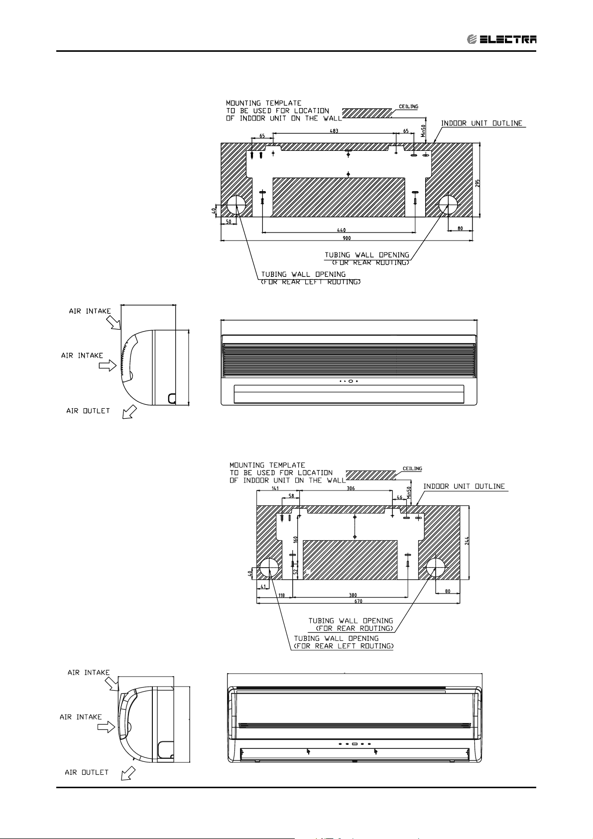
4. OUTLINE DIMENSIONS
CONTENT
4.1 Indoor Unit: Apha 7, 9 (Omega)
OUTLINE DIMENSIONS
4.2
Indoor Unit: Alpha 12 (Omega)
SM ALPHA 1-E.3 GB
4-1
Page 21
OUTLINE DIMENSIONS
CONTENT
4.3 Indoor Unit: Alpha 17
200
900
295
4.4 Indoor Unit: Alpha 9DF
4-2
180
680
250
SM ALPHA 1-E.3 GB
Page 22
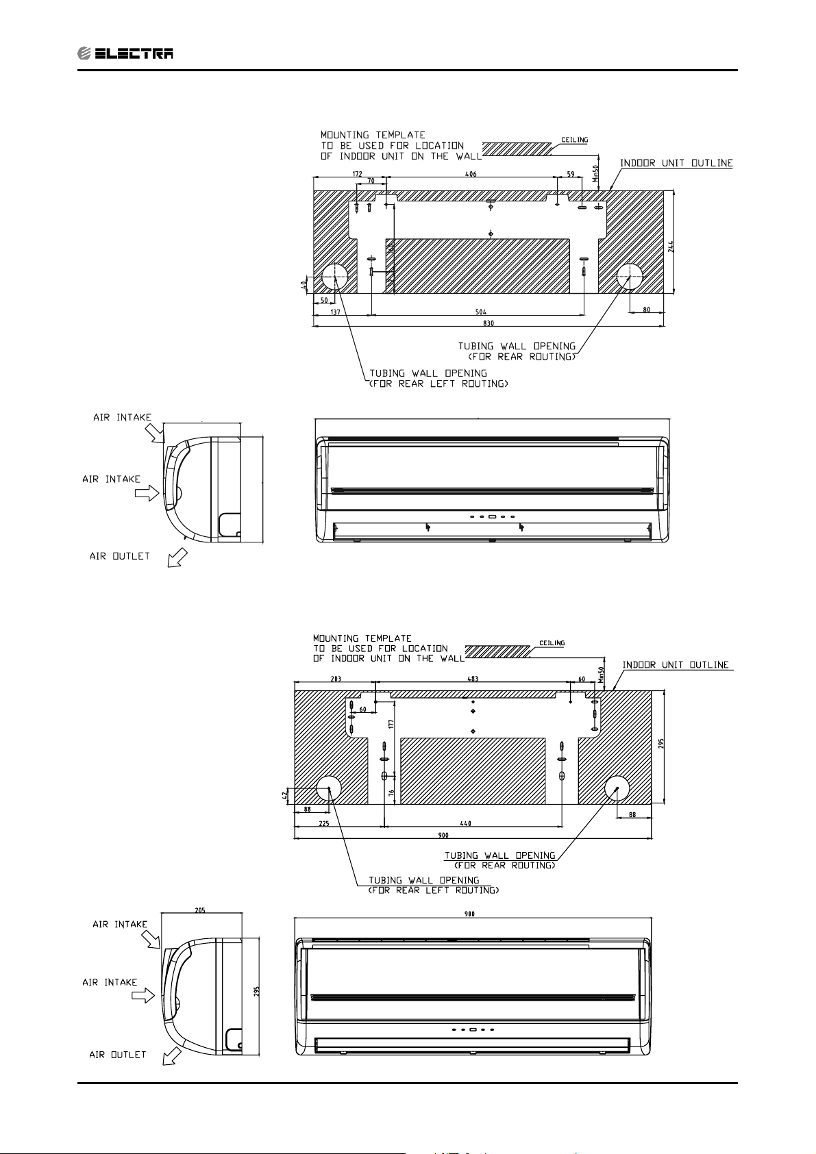
4.5 Indoor Unit: Alpha 12DF
CONTENT
OUTLINE DIMENSIONS
180
250
4.6 Indoor Unit: Delta 17F
840
SM ALPHA 1-E.3 GB
4-3
Page 23
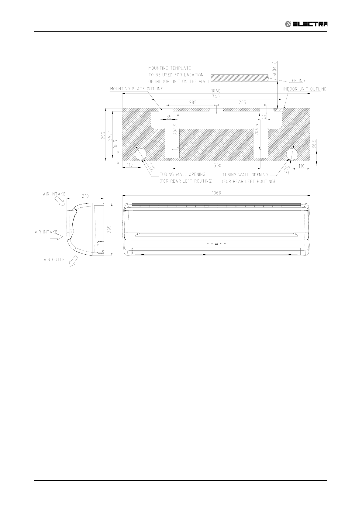
OUTLINE DIMENSIONS
CONTENT
4.7 Indoor Unit: Delta 24F
4-4
SM ALPHA 1-E.3 GB
Page 24
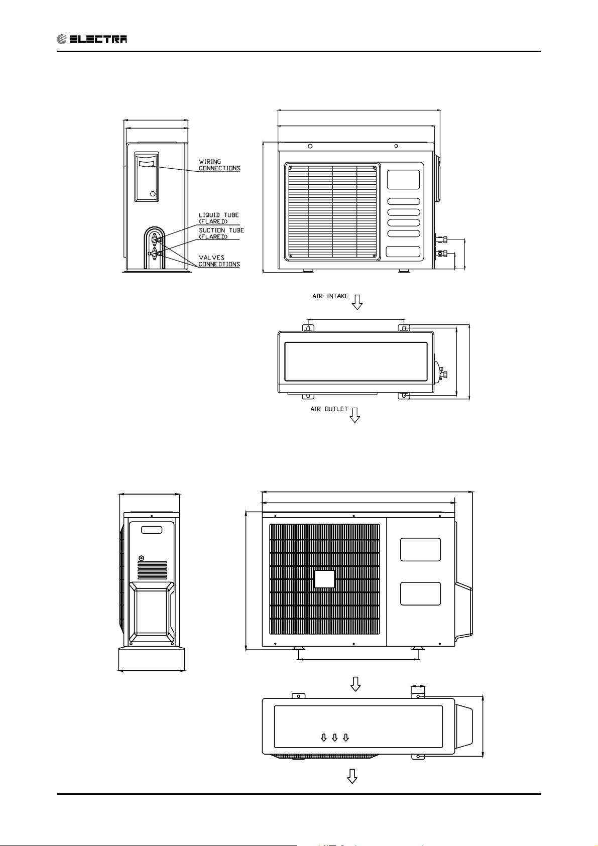
4.8 Outdoor Unit CON 7 (Alpha)
CONTENT
OUTLINE DIMENSIONS
240
235
520
650
610
403
031
57
08
842
2
4.9 Outdoor Unit GCN 7, 9, 12 (Alpha)
245
545
260
AI R I NTAKE
830
760
472
50
237
SM ALPHA 1-E.3 GB
AI R OUTL ET
4-5
Page 25
OUTLINE DIMENSIONS
CONTENT
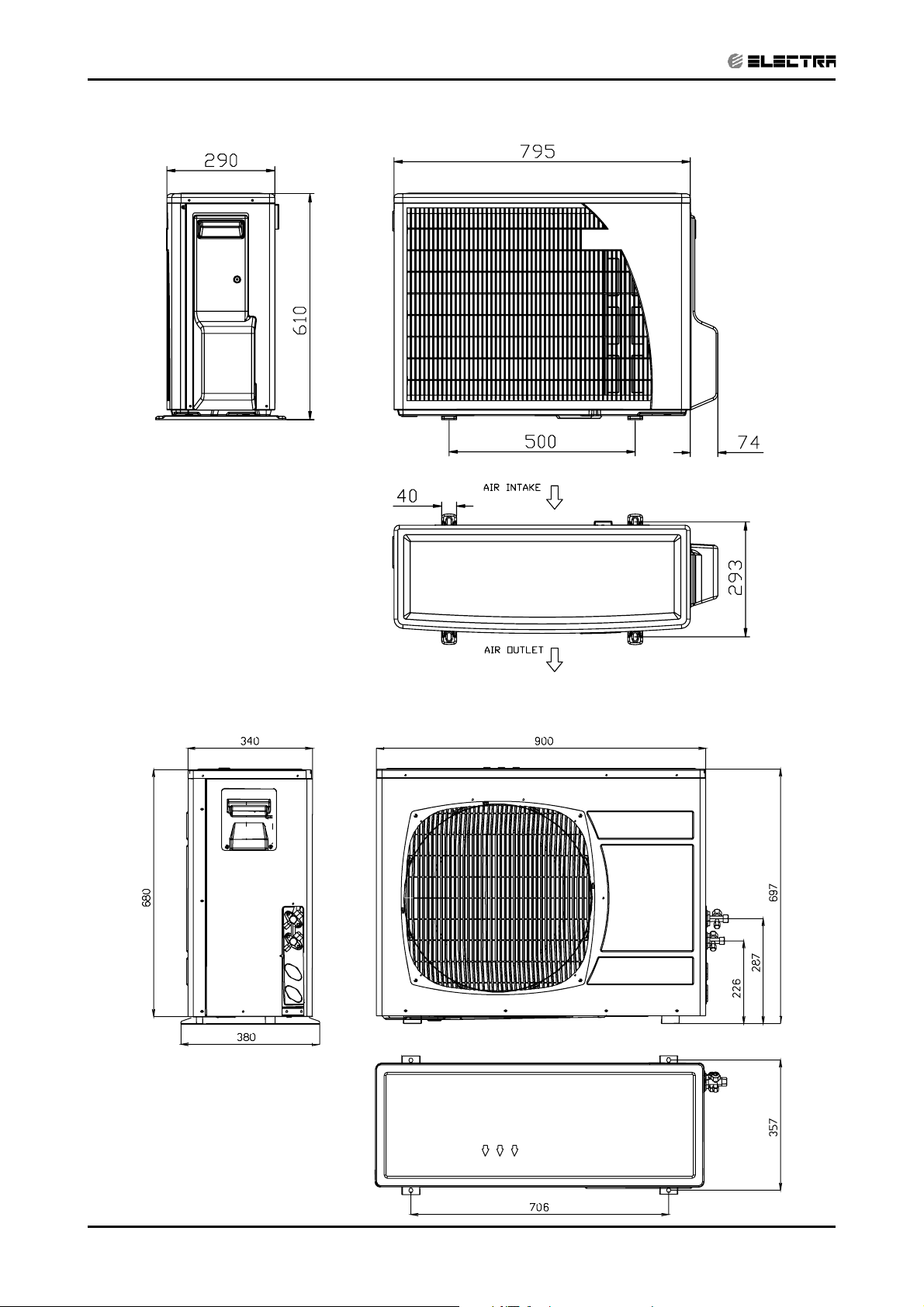
4.10 Outdoor Unit ONG3- 9, 12, 14, 17 (Alpha)
4.11 Outdoor Unit OU7-24C
4-6
SM ALPHA 1-E.3 GB
Page 26

PERFORMANCE DATA & PRESSURE CURVES
CONTENT
5. PERFORMANCE DATA & PRESSURE CURVES
5.1 Alpha7/CON7
5.1.1 Cooling Mode at 7.5m Tubing Connection.
230V : Indoor Fan at High Speed.
ENTERING AIR
DB OD Coil(
15
20
o
C)
(1)
(1)
25
30
35
40
46
o
C)
Data
ENTERING AIR WB/DB ID Coil(
15/21 17/24 19/27 21/29 23/32
TC 2.16 2.24 2.29 2.34 2.38
SC 1.49 1.55 1.61 1.65 1.68
PI 0.48 0.48 0.48 0.49 0.49
TC 2.09 2.20 2.27 2.33 2.38
SC 1.46 1.54 1.60 1.65 1.68
PI 0.52 0.53 0.53 0.53 0.53
TC 1.98 2.14 2.25 2.31 2.37
SC 1.42 1.51 1.59 1.64 1.67
PI 0.57 0.57 0.57 0.58 0.58
TC 1.85 2.01 2.18 2.25 2.32
SC 1.38 1.46 1.56 1.60 1.63
PI 0.61 0.62
TC 1.71 1.86
0.62
2.05
0.63 0.64
2.15 2.25
SC 1.31 1.40 1.52 1.56 1.59
PI 0.66 0.67
TC 1.56 1.70
0.68
1.85
0.69 0.69
2.02 2.13
SC 1.23 1.33 1.44 1.48 1.51
PI 0.71 0.72 0.73 0.74 0.75
TC 1.35 1.48 1.62 1.79 1.93
SC 1.14 1.22 1.31 1.36 1.39
PI 0.78 0.79 0.81 0.82 0.83
SM ALPHA 1-E.3 GB
LEGEND
TC – Total Cooling Capacity, kW
SC – Sensible Capacity, kW
PI – Power Input, kW
WB – Wet Bulb Temp., (
o
C)
DB – Dry Bulb Temp., (oC)
ID – Indoor
OD – Outdoor
(1) Marked area is below standard operating limits. For operating in low ambient
conditions, an A.S.K Kit is required.
5-1
Page 27
PERFORMANCE DATA & PRESSURE CURVES
CONTENT
5.1.2 Heating
ENTERING AIR DB ID COIL(Oc)
15 20 25
ENTERING
WB OD COIL(
o
C)
TH Pl TH Pl TH Pl
-10 1.13 0.50 1.09 0.54 1.04 0.56
-7 1.21 0.52 1.17 0.54 1.13 0.57
-2 1.29 0.52 1.25 0.55 1.20 0.59
2 1.57 0.55
6 2.21 0.59 2.15 0.63 2.07 0.67
10 2.41 0.62
15 2.60 0.65 2.54 0.70 2.47 0.74
20 2.74 0.67 2.68 0.72 2.60 0.78
LEGEND
TH – Total Heating Capacity, kW
PI – Power Input, kW
WB – Wet Bulb Temp., (
DB – Dry Bulb Temp., (oC)
ID – Indoor
OD – Outdoor
o
C)
1.51 0.58
2.34 0.66
1.44 0.62
2.28 0.71
5-2
SM ALPHA 1-E.3 GB
Page 28
PERFORMANCE DATA & PRESSURE CURVES
CONTENT
5.2 Model: Alpha7/CON7
5.2.1 Cooling
Discharge Pressure VS.Outdoor Temp
38
36
34
32
30
28
26
24
22
20
18
Discharge Pressure (Bar[g])
16
15 20 25 30 35 40 46
15/21(WB/DB ºC)
17/24(WB/DB ºC)
19/27(WB/DB ºC)
21/29(WB/DB ºC)
23/32(WB/DB ºC)
Outdoor Temp.(DB oC )
Suction Pressure (Bar[g])
Suction Pressure VS.Outdoor Temp
11.0
15/21(WB/DB ºC)
10.5
10.0
9.5
9.0
8.5
8.0
7.5
7.0
6.5
15 20 25 30 35 40 46
17/24(WB/DB ºC)
19/27(WB/DB ºC)
21/29(WB/DB ºC)
23/32(WB/DB ºC)
Outdoor Temp.(DB oC )
SM ALPHA 1-E.3 GB
5-3
Page 29
PERFORMANCE DATA & PRESSURE CURVES
CONTENT
5.2.2 Heating
Discharge Pressure VS.Outdoor Temp
36
34
32
30
28
26
Discharge Pressure(Bar[g])
10.0
9.0
8.0
24
22
20
18
-10 -5 0 5 10 15 20
Outdoor Temp.( WB oC )
Suction Pressure VS.Outdoor Temp
25 DB (ºC)
20 DB (ºC)
15 DB (ºC)
5-4
7.0
6.0
5.0
Suction Pressure(Bar[g])
4.0
-10 -5 0 5 10 15 20
Outdoor Temp.( WB oC )
SM ALPHA 1-E.3 GB
15 DB (ºC)
20 DB (ºC)
25 DB (ºC)
Page 30
PERFORMANCE DATA & PRESSURE CURVES
CONTENT
5.3 Alpha7 DF / GCN7 RC R410A A2
5.3.1 Cooling Mode at 7.5m Tubing Connection.
230V : Indoor Fan at High Speed.
Entering Air DB
OD Coil(oC)
15
20
25
30
35
Data
Entering Air WB/DB ID Coil(oC)
15/21 17/24 19/27 21/29 23/32
TC 2.40 2.49 2.55 2.61 2.65
SC 1.67 1.74 1.81 1.85 1.89
PI 0.44 0.44 0.44 0.44 0.44
TC 2.33 2.45 2.53 2.59 2.64
SC 1.64 1.73 1.80 1.85 1.88
PI 0.48 0.48 0.48 0.48 0.48
TC 2.20 2.38 2.50 2.57 2.64
SC 1.59 1.69 1.78 1.84 1.87
PI 0.52 0.52 0.52 0.53 0.53
TC 2.06 2.24 2.42 2.51 2.58
SC 1.54 1.64 1.75 1.80 1.83
PI 0.56 0.56 0.57 0.57 0.58
TC 1.90 2.07 2.28 2.39 2.51
SC 1.47 1.57 1.71 1.75 1.79
PI 0.60 0.61 0.62 0.62 0.63
TC 1.73 1.89 2.06 2.25 2.37
40
SC 1.38 1.49 1.61 1.66 1.70
PI 0.65 0.66 0.67 0.68 0.68
TC 1.50 1.64 1.81 2.00 2.15
46
SC 1.28 1.37 1.47 1.52 1.56
PI 0.71 0.72 0.73 0.74 0.75
LEGEND
TC – Total Cooling Capacity, kW
SC – Sensible Capacity, kW
PI – Power Input, kW
WB – Wet Bulb Temp., (
DB – Dry Bulb Temp., (oC)
ID – Indoor
OD – Outdoor
(1) Marked area is below standard operating limits. For operating in low ambient
conditions, an A.S.K Kit is required.
o
C)
SM ALPHA 1-E.3 GB
5-5
Page 31

PERFORMANCE DATA & PRESSURE CURVES
CONTENT
5.3.2 Heating
ENTERING AIR DB ID COIL(OC)
15 20 25
ENTERING WB
o
OD COIL(
C)
-10 1.21 0.54 1.16 0.57 1.12 0.60
-7 1.30 0.55 1.25 0.58 1.21 0.61
-2 1.38 0.56 1.33 0.59 1.29 0.62
2 1.68 0.58 1.61 0.62 1.54 0.66
6 2.37 0.63 2.30 0.67 2.22 0.71
10 2.58 0.66 2.51 0.71 2.44 0.76
15 2.78 0.69 2.71 0.74 2.65 0.79
20 2.93 0.71 2.86 0.77 2.78 0.83
LEGEND
TH – Total Heating Capacity, kW
PI – Power Input, kW
WB – Wet Bulb Temp., (oC)
DB – Dry Bulb Temp., (oC)
ID – Indoor
OD – Outdoor
TH Pl TH Pl TH Pl
5-6
SM ALPHA 1-E.3 GB
Page 32

PERFORMANCE DATA & PRESSURE CURVES
CONTENT
5.4 Alpha7 DF / GCN7 RC R410A A2
5.4.1 Cooling
Discharge Pressure VS.Outdoor Temp
36
34
32
30
28
26
24
22
20
18
16
14
Discharge Pressure (Bar[g])
12
15 20 25 30 35 40 46
15/21(WB/DB ºC)
17/24(WB/DB ºC)
19/27(WB/DB ºC)
21/29(WB/DB ºC)
23/32(WB/DB ºC)
Outdoor Temp.(DB oC )
Suction Pressure VS.Outdoor Temp
12.0
11.0
10.0
9.0
8.0
7.0
6.0
Suction Pressure (Bar[g])
5.0
15 20 25 30 35 40 46
15/21(WB/DB ºC)
17/24(WB/DB ºC)
19/27(WB/DB ºC)
21/29(WB/DB ºC)
23/32(WB/DB ºC)
Outdoor Temp.(DB oC )
SM ALPHA 1-E.3 GB
5-7
Page 33

PERFORMANCE DATA & PRESSURE CURVES
CONTENT
5.4.2 Heating
Discharge Pressure VS.Outdoor Temp
36
34
32
30
28
26
24
22
20
18
Discharge Pressure(Bar[g])
16
-10 -5 0 5 10 15 20
Outdoor Temp.( WB oC )
25 DB (ºC)
20 DB (ºC)
15 DB (ºC)
Suction Pressure(Bar[g])
Suction Pressure VS.Outdoor Temp
12.0
11.0
10.0
9.0
8.0
7.0
6.0
5.0
4.0
3.0
-10-5 0 5 101520
15 DB (ºC)
20 DB (ºC)
25 DB (ºC)
Outdoor Temp.( WB oC )
5-8
SM ALPHA 1-E.3 GB
Page 34

PERFORMANCE DATA & PRESSURE CURVES
CONTENT
5.5 Alpha9 / GCN9
5.5.1 Cooling Mode at 7.5m Tubing Connection.
230V : Indoor Fan at High Speed.
ENTERING AIR
DB OD Coil(oC)
(1)
15
(1)
20
25
30
35
40
46
o
C)
Data
ENTERING AIR WB/DB ID Coil(
15/21 17/24 19/27 21/29 23/32
TC 2.78 2.88 2.95 3.02 3.07
SC 1.78 1.86 1.93 1.98 2.02
PI
TC
0.62 0.62 0.62 0.62 0.62
2.69 2.84 2.93 3.00 3.06
SC 1.75 1.84 1.92 1.97 2.01
PI
TC
0.67 0.67 0.67 0.68 0.68
2.55 2.75 2.89 2.98 3.05
SC 1.70 1.81 1.90 1.96 2.00
PI
TC
0.72 0.73 0.73 0.74 0.74
2.38 2.59 2.80 2.90 2.99
SC 1.65 1.75 1.86 1.92 1.95
PI
TC
0.78 0.79
2.21 2.39
0.80
2.64
0.81 0.81
2.77 2.90
SC 1.57 1.68 1.82 1.87 1.91
PI
TC
0.84 0.86
2.01 2.18
0.87
2.38
0.88 0.88
2.60 2.74
SC 1.48 1.59 1.72 1.78 1.81
PI
TC
0.91 0.92 0.94 0.95 0.96
1.74 1.90 2.09 2.31 2.49
SC 1.36 1.46 1.57 1.62 1.66
PI 0.99 1.01 1.03 1.04 1.06
SM ALPHA 1-E.3 GB
LEGEND
TC – Total Cooling Capacity, kW
SC – Sensible Capacity, kW
PI – Power Input, kW
WB – Wet Bulb Temp., (
o
C)
DB – Dry Bulb Temp., (oC)
ID – Indoor
OD – Outdoor
(1) Marked area is below standard operating limits. For operating in low ambient
conditions, an A.S.K Kit is required.
5-9
Page 35

PERFORMANCE DATA & PRESSURE CURVES
CONTENT
5.5.2 Heating
ENTERING AIR DB ID COIL(Oc)
15 20 25
ENTERING
WB OD COIL(
-10
o
C)
TH Pl TH Pl TH Pl
1.49 0.74 1.43 0.79 1.37 0.83
-7 1.60 0.76 1.54 0.80 1.49 0.85
-2 1.70 0.77 1.64 0.82 1.58 0.86
2 2.07 0.81
6 2.91 0.87 2.83 0.93 2.73 0.99
10 3.17 0.92
15 3.42 0.96 3.34 1.03 3.25 1.10
20 3.61 0.99 3.52 1.07 3.42 1.15
LEGENDw
TH – Total Heating Capacity, kW
PI – Power Input, kW
WB – Wet Bulb Temp., (
DB – Dry Bulb Temp., (oC)
ID – Indoor
OD – Outdoor
o
C)
1.98 0.86
3.08 0.98
1.90 0.91
3.00 1.05
5-10
SM ALPHA 1-E.3 GB
Page 36

5.6 Model: Alpha9 / GCN9
CONTENT
5.6.1 Cooling
Discharge Pressure VS.Outdoor Temp
38
36
34
32
30
28
26
24
22
20
18
Discharge Pressure (Bar[g])
16
15 20 25 30 35 40 46
15/21(WB/DB ºC)
17/24(WB/DB ºC)
19/27(WB/DB ºC)
21/29(WB/DB ºC)
23/32(WB/DB ºC)
Outdoor Temp.(DB oC )
PERFORMANCE DATA & PRESSURE CURVES
Suction Pressure (Bar[g])
Suction Pressure VS.Outdoor Temp
11.0
10.5
10.0
9.5
9.0
8.5
8.0
7.5
7.0
6.5
15 20 25 30 35 40 46
15/21(WB/DB ºC)
17/24(WB/DB ºC)
19/27(WB/DB ºC)
21/29(WB/DB ºC)
23/32(WB/DB ºC)
Outdoor Temp.(DB oC )
SM ALPHA 1-E.3 GB
5-11
Page 37

PERFORMANCE DATA & PRESSURE CURVES
CONTENT
5.6.2 Heating
Discharge Pressure VS.Outdoor Temp
40
38
36
34
32
30
28
Discharge Pressure(Bar[g])
11.0
10.0
26
24
22
20
-10 -5 0 5 10 15 20
Outdoor Temp.( WB oC )
Suction Pressure VS.Outdoor Temp
9.0
8.0
7.0
25 DB (ºC)
20 DB (ºC)
15 DB (ºC)
5-12
6.0
5.0
4.0
Suction Pressure(Bar[g])
3.0
-10 -5 0 5 10 15 20
15 DB (ºC)
20 DB (ºC)
25 DB (ºC)
Outdoor Temp.( WB oC )
SM ALPHA 1-E.3 GB
Page 38

PERFORMANCE DATA & PRESSURE CURVES
CONTENT
5.7 Alpha9 DF / ONG3-9 RC R410A B2
5.7.1 Cooling Mode at 7.5m Tubing Connection.
230V : Indoor Fan at High Speed.
Entering Air DB
OD Coil(oC)
15
20
25
30
35
Data
Entering Air WB/DB ID Coil(oC)
15/21 17/24 19/27 21/29 23/32
TC 2.85 2.95 3.02 3.09 3.14
SC 1.82 1.90 1.97 2.02 2.06
PI 0.53 0.53 0.53 0.54 0.54
TC 2.75 2.90 2.99 3.06 3.13
SC 1.79 1.88 1.96 2.02 2.05
PI 0.58 0.58 0.58 0.58 0.59
TC 2.61 2.81 2.96 3.05 3.12
SC 1.74 1.85 1.95 2.00 2.04
PI 0.62 0.63 0.63 0.64 0.64
TC 2.44 2.65 2.87 2.97 3.06
SC 1.68 1.79 1.90 1.96 2.00
PI 0.67 0.68 0.69 0.69 0.70
TC 2.26 2.45 2.70 2.84 2.97
SC 1.60 1.72 1.86 1.91 1.95
PI 0.73 0.74 0.75 0.76 0.76
TC 2.05 2.23 2.44 2.66 2.80
40
SC 1.51 1.63 1.76 1.82 1.85
PI 0.78 0.80 0.81 0.82 0.83
TC 1.78 1.95 2.14 2.36 2.55
46
SC 1.39 1.49 1.60 1.66 1.70
PI 0.86 0.87 0.89 0.90 0.91
LEGEND
TC – Total Cooling Capacity, kW
SC – Sensible Capacity, kW
PI – Power Input, kW
WB – Wet Bulb Temp., (oC)
DB – Dry Bulb Temp., (
ID – Indoor
OD – Outdoor
(1) Marked area is below standard operating limits. For operating in low ambient
conditions, an A.S.K Kit is required.
o
C)
SM ALPHA 1-E.3 GB
5-13
Page 39

PERFORMANCE DATA & PRESSURE CURVES
CONTENT
5.7.2 Heating
ENTERING AIR DB ID COIL(OC)
15 20 25
ENTERING WB
OD COIL(oC)
TH Pl TH Pl TH Pl
-10 1.52 0.66 1.46 0.71 1.41 0.74
-7 1.64 0.68 1.58 0.72 1.52 0.76
-2 1.74 0.69 1.68 0.73 1.62 0.77
2 2.12 0.72 2.03 0.77 1.94 0.81
6 2.99 0.78 2.90 0.83 2.80 0.88
10 3.25 0.82 3.16 0.88 3.07 0.94
15 3.51 0.85 3.42 0.92 3.34 0.98
20 3.70 0.88 3.61 0.95 3.51 1.03
LEGEND
TH – Total Heating Capacity, kW
PI – Power Input, kW
WB – Wet Bulb Temp., (oC)
DB – Dry Bulb Temp., (oC)
ID – Indoor
OD – Outdoor
5-14
SM ALPHA 1-E.3 GB
Page 40

PERFORMANCE DATA & PRESSURE CURVES
CONTENT
5.8 Alpha9 DF / ONG3-9 RC R410A B2
5.8.1 Cooling
Discharge Pressure VS.Outdoor Temp
36
34
32
30
28
26
24
22
20
18
16
14
Discharge Pressure (Bar[g])
12
15 20 25 30 35 40 46
15/21(WB/DB ºC)
17/24(WB/DB ºC)
19/27(WB/DB ºC)
21/29(WB/DB ºC)
23/32(WB/DB ºC)
Outdoor Temp.(DB oC )
Suction Pressure VS.Outdoor Temp
12.0
11.0
10.0
9.0
8.0
7.0
6.0
Suction Pressure (Bar[g])
5.0
15 20 25 30 35 40 46
15/21(WB/DB ºC)
17/24(WB/DB ºC)
19/27(WB/DB ºC)
21/29(WB/DB ºC)
23/32(WB/DB ºC)
Outdoor Temp.(DB oC )
SM ALPHA 1-E.3 GB
5-15
Page 41

PERFORMANCE DATA & PRESSURE CURVES
CONTENT
5.8.2 Heating
Discharge Pressure VS.Outdoor Temp
38
36
34
32
30
28
26
24
22
20
18
Discharge Pressure(Bar[g])
16
-10 -5 0 5 10 15 20
Outdoor Temp.( WB oC )
25 DB (ºC)
20 DB (ºC)
15 DB (ºC)
Suction Pressure(Bar[g])
Suction Pressure VS.Outdoor Temp
11.0
10.0
9.0
8.0
7.0
6.0
5.0
4.0
3.0
-10-5 0 5 101520
15 DB (ºC)
20 DB (ºC)
25 DB (ºC)
Outdoor Temp.( WB oC )
5-16
SM ALPHA 1-E.3 GB
Page 42

PERFORMANCE DATA & PRESSURE CURVES
CONTENT
5.9 Alpha12 / GCN12
5.9.1 Cooling Mode at 7.5m Tubing Connection.
230V : Indoor Fan at High Speed.
ENTERING AIR
DB OD Coil(oC)
(1)
15
(1)
20
25
30
35
40
46
o
C)
Data
ENTERING AIR WB/DB ID Coil(
15/21 17/24 19/27 21/29 23/32
TC
3.69 3.82 3.91 4.00 4.06
SC 2.42 2.52 2.62 2.69 2.74
PI
TC
0.82 0.82 0.83 0.83 0.83
3.57 3.76 3.88 3.97 4.06
SC 2.37 2.50 2.60 2.68 2.73
PI
TC
0.89 0.90 0.90 0.90 0.91
3.38 3.65 3.83 3.95 4.05
SC 2.31 2.45 2.59 2.66 2.71
PI
TC
0.96 0.97 0.98 0.98 0.99
3.16 3.44 3.71 3.85 3.96
SC 2.24 2.38 2.53 2.60 2.65
PI
TC
1.04 1.06
2.92 3.17
1.07
3.50
1.07 1.08
3.68 3.85
SC 2.13 2.28 2.47 2.54 2.59
PI
TC
1.12 1.14
2.66 2.89
1.16
3.16
1.17 1.18
3.45 3.63
SC 2.01 2.16 2.34 2.41 2.46
PI
TC
1.21 1.23 1.25 1.27 1.28
2.31 2.52 2.77 3.06 3.30
SC 1.85 1.98 2.13 2.20 2.25
PI
1.32 1.34 1.37 1.39 1.41
SM ALPHA 1-E.3 GB
LEGEND
TC – Total Cooling Capacity, kW
SC – Sensible Capacity, kW
PI – Power Input, kW
WB – Wet Bulb Temp., (
o
C)
DB – Dry Bulb Temp., (oC)
ID – Indoor
OD – Outdoor
(1) Marked area is below standard operating limits. For operating in low ambient
conditions, an A.S.K Kit is required
5-17
Page 43

PERFORMANCE DATA & PRESSURE CURVES
CONTENT
5.9.2 Heating
ENTERING AIR DB ID COIL(Oc)
15 20 25
ENTERING
WB OD COIL(
o
C)
TH Pl TH Pl TH Pl
-10 1.98 0.94 1.91 1.00 1.83 1.05
-7 2.14 0.96 2.06 1.01 1.98 1.07
-2 2.27 0.97 2.19 1.03 2.12 1.09
2 2.76 1.02
6 3.89 1.09 3.78 1.17 3.65 1.24
10 4.23 1.15
15 4.57 1.21 4.46 1.30 4.35 1.38
20 4.82 1.24 4.71 1.35 4.57 1.45
LEGEND
TH – Total Heating Capacity, kW
PI – Power Input, kW
WB – Wet Bulb Temp., (
o
DB – Dry Bulb Temp., (oC)
ID – Indoor
OD – Outdoor
C)
2.65 1.08
4.12 1.23
2.53 1.15
4.01 1.32
5-18
SM ALPHA 1-E.3 GB
Page 44

5.10 Model: Alpha12 / GCN12
CONTENT
5.10.1 Cooling
Discharge Pressure VS.Outdoor Temp
38
36
34
32
30
28
26
24
22
20
18
Discharge Pressure (Bar[g])
16
15 20 25 30 35 40 46
15/21(WB/DB ºC)
17/24(WB/DB ºC)
19/27(WB/DB ºC)
21/29(WB/DB ºC)
23/32(WB/DB ºC)
Outdoor Temp.(DB oC )
PERFORMANCE DATA & PRESSURE CURVES
Suction Pressure (Bar[g])
Suction Pressure VS.Outdoor Temp
10.5
15/21(WB/DB ºC)
10.0
9.5
9.0
8.5
8.0
7.5
7.0
6.5
6.0
15 20 25 30 35 40 46
17/24(WB/DB ºC)
19/27(WB/DB ºC)
21/29(WB/DB ºC)
23/32(WB/DB ºC)
Outdoor Temp.(DB oC )
SM ALPHA 1-E.3 GB
5-19
Page 45

PERFORMANCE DATA & PRESSURE CURVES
CONTENT
5.10.2 Heating
Discharge Pressure VS.Outdoor Temp
38
36
34
32
30
28
26
24
22
Discharge Pressure(Bar[g])
20
-10 -5 0 5 10 15 20
Outdoor Temp.( WB oC )
25 DB (ºC)
20 DB (ºC)
15 DB (ºC)
Suction Pressure(Bar[g])
Suction Pressure VS.Outdoor Temp
11.0
10.0
9.0
8.0
7.0
6.0
5.0
4.0
3.0
-10-5 0 5 101520
15 DB (ºC)
20 DB (ºC)
25 DB (ºC)
Outdoor Temp.( WB oC )
5-20
SM ALPHA 1-E.3 GB
Page 46

PERFORMANCE DATA & PRESSURE CURVES
CONTENT
5.11 Alpha12 DF / ONG3-12 RC R410A B2
5.11.1 Cooling Mode at 7.5m Tubing Connection.
230V : Indoor Fan at High Speed.
Entering Air DB
OD Coil(oC)
15
20
25
30
35
Data
Entering Air WB/DB ID Coil(oC)
15/21 17/24 19/27 21/29 23/32
TC 3.74 3.88 3.97 4.06 4.12
SC 2.46 2.56 2.66 2.73 2.78
PI 0.70 0.70 0.70 0.71 0.71
TC 3.62 3.82 3.94 4.03 4.12
SC 2.41 2.54 2.65 2.72 2.77
PI 0.76 0.76 0.77 0.77 0.77
TC 3.43 3.70 3.89 4.01 4.10
SC 2.35 2.49 2.63 2.70 2.75
PI 0.82 0.83 0.83 0.84 0.85
TC 3.20 3.49 3.77 3.90 4.02
SC 2.27 2.42 2.57 2.65 2.70
PI 0.89 0.90 0.91 0.92 0.92
TC 2.97 3.22 3.55 3.73 3.90
SC 2.16 2.32 2.51 2.58 2.63
PI 0.96 0.97 0.99 1.00 1.00
TC 2.70 2.94 3.20 3.50 3.68
40
SC 2.04 2.19 2.38 2.45 2.50
PI 1.03 1.05 1.07 1.08 1.09
TC 2.34 2.56 2.81 3.11 3.35
46
SC 1.88 2.01 2.17 2.24 2.29
PI 1.13 1.15 1.17 1.19 1.20
LEGEND
TC – Total Cooling Capacity, kW
SC – Sensible Capacity, kW
PI – Power Input, kW
WB – Wet Bulb Temp., (
DB – Dry Bulb Temp., (oC)
ID – Indoor
OD – Outdoor
(1) Marked area is below standard operating limits. For operating in low ambient
conditions, an A.S.K Kit is required
o
C)
SM ALPHA 1-E.3 GB
5-21
Page 47

PERFORMANCE DATA & PRESSURE CURVES
CONTENT
5.11.2 Heating
ENTERING AIR DB ID COIL(OC)
15 20 25
ENTERING WB
OD COIL(oC)
TH Pl TH Pl TH Pl
-10 1.94 0.82 1.87 0.88 1.79 0.92
-7 2.09 0.84 2.02 0.89 1.94 0.94
-2 2.22 0.85 2.15 0.91 2.07 0.96
2 2.70 0.90 2.59 0.95 2.48 1.01
6 3.81 0.96 3.70 1.03 3.57 1.09
10 4.14 1.02 4.03 1.09 3.92 1.16
15 4.48 1.06 4.37 1.14 4.26 1.22
20 4.72 1.09 4.61 1.18 4.48 1.28
LEGEND
TH – Total Heating Capacity, kW
PI – Power Input, kW
WB – Wet Bulb Temp., (oC)
DB – Dry Bulb Temp., (oC)
ID – Indoor
OD – Outdoor
5-22
SM ALPHA 1-E.3 GB
Page 48

PERFORMANCE DATA & PRESSURE CURVES
CONTENT
5.12 Model: Alpha12 DF / ONG3-12 RC R410A B2
5.12.1 Cooling
Discharge Pressure VS.Outdoor Temp
36
34
32
30
28
26
24
22
20
18
16
14
Discharge Pressure (Bar[g])
12
15 20 25 30 35 40 46
15/21(WB/DB ºC)
17/24(WB/DB ºC)
19/27(WB/DB ºC)
21/29(WB/DB ºC)
23/32(WB/DB ºC)
Outdoor Temp.(DB oC )
Suction Pressure VS.Outdoor Temp
12.0
11.0
10.0
9.0
8.0
7.0
6.0
Suction Pressure (Bar[g])
5.0
15 20 25 30 35 40 46
15/21(WB/DB ºC)
17/24(WB/DB ºC)
19/27(WB/DB ºC)
21/29(WB/DB ºC)
23/32(WB/DB ºC)
Outdoor Temp.(DB oC )
SM ALPHA 1-E.3 GB
5-23
Page 49

PERFORMANCE DATA & PRESSURE CURVES
CONTENT
5.12.2 Heating
Discharge Pressure VS.Outdoor Temp
36
34
32
30
28
26
24
22
20
18
Discharge Pressure(Bar[g])
16
-10 -5 0 5 10 15 20
Outdoor Temp.( WB oC )
25 DB (ºC)
20 DB (ºC)
15 DB (ºC)
Suction Pressure VS.Outdoor Temp
11.0
10.0
9.0
8.0
7.0
6.0
5.0
4.0
Suction Pressure(Bar[g])
3.0
-10-5 0 5 101520
15 DB (ºC)
20 DB (ºC)
25 DB (ºC)
Outdoor Temp.( WB oC )
5-24
SM ALPHA 1-E.3 GB
Page 50

PERFORMANCE DATA & PRESSURE CURVES
CONTENT
5.13 Alpha17 DF / ONG3-14 RC R410A B2
5.13.1 Cooling Mode at 7.5m Tubing Connection.
230V : Indoor Fan at High Speed.
Entering Air DB
OD Coil(oC)
15
20
25
30
35
Data
Entering Air WB/DB ID Coil(oC)
15/21 17/24 19/27 21/29 23/32
TC 4.95 5.13 5.25 5.38 5.46
SC 3.06 3.19 3.32 3.40 3.46
PI 0.99 0.99 1.00 1.00 1.00
TC 4.79 5.05 5.21 5.33 5.45
SC 3.00 3.16 3.30 3.39 3.45
PI 1.08 1.08 1.08 1.09 1.09
TC 4.53 4.90 5.15 5.30 5.43
SC 2.92 3.10 3.27 3.37 3.43
PI 1.16 1.17 1.18 1.19 1.20
TC 4.24 4.62 4.99 5.17 5.32
SC 2.83 3.01 3.20 3.29 3.36
PI 1.26 1.27 1.29 1.30 1.31
TC 3.93 4.26 4.70 4.94 5.17
SC 2.69 2.89 3.13 3.22 3.28
PI 1.35 1.38 1.40 1.41 1.42
TC 3.57 3.89 4.24 4.64 4.88
40
SC 2.54 2.73 2.96 3.05 3.11
PI 1.46 1.48 1.51 1.53 1.54
TC 3.10 3.39 3.72 4.12 4.43
46
SC 2.34 2.50 2.70 2.79 2.85
PI 1.60 1.62 1.66 1.68 1.70
LEGEND
TC – Total Cooling Capacity, kW
SC – Sensible Capacity, kW
PI – Power Input, kW
WB – Wet Bulb Temp., (
DB – Dry Bulb Temp., (oC)
ID – Indoor
OD – Outdoor
(1) Marked area is below standard operating limits. For operating in low ambient
conditions, an A.S.K Kit is required
o
C)
SM ALPHA 1-E.3 GB
5-25
Page 51

PERFORMANCE DATA & PRESSURE CURVES
CONTENT
5.13.2 Heating
ENTERING AIR DB ID COIL(OC)
15 20 25
ENTERING WB
OD COIL(oC)
TH Pl TH Pl TH Pl
-10 2.57 1.12 2.47 1.19 2.38 1.25
-7 2.77 1.15 2.67 1.21 2.57 1.28
-2 2.94 1.16 2.84 1.23 2.74 1.30
2 3.58 1.22 3.43 1.30 3.28 1.37
6 5.05 1.31 4.90 1.40 4.73 1.49
10 5.49 1.38 5.34 1.48 5.19 1.58
15 5.93 1.44 5.78 1.55 5.64 1.65
20 6.25 1.48 6.10 1.61 5.93 1.74
LEGEND
TH – Total Heating Capacity, kW
PI – Power Input, kW
WB – Wet Bulb Temp., (oC)
DB – Dry Bulb Temp., (oC)
ID – Indoor
OD – Outdoor
5-26
SM ALPHA 1-E.3 GB
Page 52

PERFORMANCE DATA & PRESSURE CURVES
CONTENT
5.14 Model: Alpha17 DF / ONG3-14 RC R410A B2
5.14.1 Cooling
Discharge Pressure VS.Outdoor Temp
36
34
32
30
28
26
24
22
20
18
16
14
Discharge Pressure (Bar[g])
12
15 20 25 30 35 40 46
15/21(WB/DB ºC)
17/24(WB/DB ºC)
19/27(WB/DB ºC)
21/29(WB/DB ºC)
23/32(WB/DB ºC)
Outdoor Temp.(DB oC )
Suction Pressure VS.Outdoor Temp
12.0
11.0
10.0
9.0
8.0
7.0
6.0
Suction Pressure (Bar[g])
5.0
15 20 25 30 35 40 46
15/21(WB/DB ºC)
17/24(WB/DB ºC)
19/27(WB/DB ºC)
21/29(WB/DB ºC)
23/32(WB/DB ºC)
Outdoor Temp.(DB oC )
SM ALPHA 1-E.3 GB
5-27
Page 53

PERFORMANCE DATA & PRESSURE CURVES
CONTENT
5.14.2 Heating
Discharge Pressure VS.Outdoor Temp
38
36
34
32
30
28
26
24
22
20
18
Discharge Pressure(Bar[g])
16
-10 -5 0 5 10 15 20
Outdoor Temp.( WB oC )
25 DB (ºC)
20 DB (ºC)
15 DB (ºC)
Suction Pressure(Bar[g])
Suction Pressure VS.Outdoor Temp
11.0
10.0
9.0
8.0
7.0
6.0
5.0
4.0
3.0
-10 -5 0 5 10 15 20
15 DB (ºC)
20 DB (ºC)
25 DB (ºC)
Outdoor Temp.( WB oC )
5-28
SM ALPHA 1-E.3 GB
Page 54

PERFORMANCE DATA & PRESSURE CURVES
CONTENT
5.15 Model: Alpha17/ ONG17 R410A
5.15.1 Cooling Mode at 7.5m Tubing Connection.
230V : Indoor Fan at High Speed.
ENTERING AIR
DB OD COIL (°C)
(1)
15
(1)
20
25
30
35
40
46
DATA
TC
SC
PI
TC
SC
PI
TC
SC
PI
TC
SC
PI
TC
SC
PI
TC
SC
PI
TC
SC
PI
ENTERING AIR WB/DB ID COIL ( °C)
15/21 17/24 19/27 21/29 23/32
5.43 5.62 5.75 5.89 5.98
3.56 3.72 3.86 3.96 4.03
1.21 1.21 1.21 1.21 1.22
5.25 5.54 5.71 5.85 5.97
3.49 3.68 3.84 3.95 4.02
1.31 1.31 1.32 1.32 1.33
4.97 5.36 5.64 5.81 5.95
3.40 3.61 3.81 3.92 3.99
1.41 1.42 1.43 1.44 1.45
4.65 5.06 5.47 5.66 5.83
3.30 3.50 3.73 3.84 3.91
1.53 1.55
1.56
1.57 1.59
4.30 4.67 5.15 5.41 5.66
3.14 3.36 3.64 3.75 3.82
1.65 1.67 1.70 1.71 1.72
3.91 4.26
4.65
5.08 5.34
2.95 3.18 3.44 3.55 3.63
1.77 1.80 1.83 1.86 1.87
3.39 3.71 4.08 4.51 4.86
2.72 2.92 3.14 3.25 3.32
1.94 1.97 2.01 2.04 2.06
LEGEND
TC – Total Cooling Capacity, kWv
SC – Sensible Capacity, kW
PI – Power Input, kW
WB – Wet Bulb Temp., (
DB – Dry Bulb Temp., (oC)
ID – Indoor
OD – Outdoor
(1) Marked area is below standard operating limits. For operating in low ambient
conditions, refer to Optional Accessories (Chapter 15).
SM ALPHA 1-E.3 GB
o
C)
5-29
Page 55

PERFORMANCE DATA & PRESSURE CURVES
CONTENT
5.15.2 Heating Mode at 7.5m Tubing Connection.
230V : Indoor Fan at High Speed.
ENTERING AIR DB ID COIL ( °C)
15 20 25
ENTERING AIR
WB OU COIL ( °C)
-10 2.81 1.32 2.70 1.41 2.59 1.48
-7 3.02 1.35 2.92 1.43 2.81 1.50
-2 3.21 1.37 3.10 1.45 3.00 1.53
2 3.91 1.44
6 5.51 1.54 5.35 1.65 5.16 1.75
10 5.99 1.63
15 6.47 1.70 6.31 1.83 6.15 1.95
20 6.82 1.75 6.66 1.90 6.47 2.05
TH PI TH PI TH PI
3.75 1.53
5.83 1.74
* the above chart includes the weighted deicing infl euence.
3.58 1.62
5.67 1.86
LEGEND
TH – Total Heating Capacity, kW
PI – Power Input, kW
WB – Wet Bulb Temp., (oC)
DB – Dry Bulb Temp., (oC)
ID – Indoor
OU – Outdoor
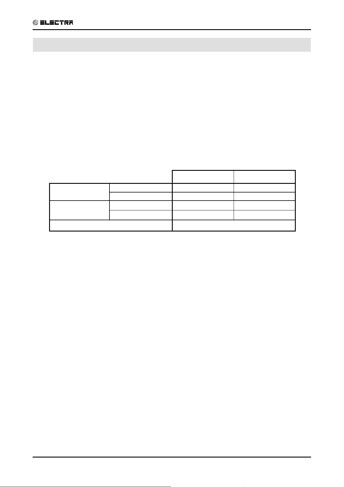
5.16 Capacity Correction Factor Due to Tubing Length
5.16.1 Cooling
TOTAL TUBING LENGTH (One Way)
Model
Alpha7,9,12,17
3m
1.02
7.5m
1
10m 15m 20m 25m 30m 40m 50m
0.97 0.95 --- --- --- --- ---
* Minimum recommended tubing length between indoor and outdoor units is 3m.
5.16.2 Heating
5-30
TOTAL TUBING LENGTH(One Way)
Model
Alpha7,9,12,17
3m
1.03
7.5m
1
10m 15m 20m 25m 30m 40m 50m
0.98 0.96 --- --- --- --- ---
* Minimum recommended tubing length between indoor and outdoor units is 3m.
SM ALPHA 1-E.3 GB
Page 56

5.17 Model: Alpha17/ONG3-17
CONTENT
5.17.1 Cooling
Discharge Pressure VS.Outdoor Temp
40
38
36
34
32
30
28
26
24
22
20
18
Discharge Pressure (Bar[g])
16
15 20 25 30 35 40 46
15/21(WB/ DB ºC)
17/24(WB/ DB ºC)
19/27(WB/ DB ºC)
21/29(WB/ DB ºC)
23/32(WB/ DB ºC)
PERFORMANCE DATA & PRESSURE CURVES
Outdoor Temp.(DB oC )
Suction Pressure VS.Outdoor Temp
11.0
10.5
10.0
9.5
9.0
8.5
8.0
7.5
7.0
Suction Pressure (Bar[g])
6.5
15 20 25 30 35 40 46
15/21(WB/DB ºC)
17/24(WB/DB ºC)
19/27(WB/DB ºC)
21/29(WB/DB ºC)
23/32(WB/DB ºC)
SM ALPHA 1-E.3 GB
Outdoor Temp.(DB oC )
5-31
Page 57

PERFORMANCE DATA & PRESSURE CURVES
CONTENT
5.17.2 Heating.
Discharge Pressure VS.Outdoor Temp
40
38
36
34
32
30
28
26
24
22
20
Discharge Pressure(Bar[g])
18
-10-5 0 5 101520
Outdoor Temp.( WB oC )
25 DB (ºC)
20 DB (ºC)
15 DB (ºC)
Suction Pressure VS.Outdoor Temp
11.0
10.0
9.0
8.0
7.0
6.0
5.0
Suction Pressure(Bar[g])
4.0
-10-5 0 5 101520
15 DB (ºC)
20 DB (ºC)
25 DB (ºC)
Outdoor Temp.( WB oC )
5-32
SM ALPHA 1-E.3 GB
Page 58

PERFORMANCE DATA & PRESSURE CURVES
CONTENT
5.18 Model: ALPHA17 DF / ONG3-17RC R410A B2
5.18.1 Cooling Mode at 7.5m Tubing Connection.
230V : Indoor Fan at High Speed.
Entering Air DB
OD Coil(oC)
15
20
25
30
35
Data
Entering Air WB/DB ID Coil(oC)
15/21 17/24 19/27 21/29 23/32
TC 5.69 5.89 6.03 6.18 6.27
SC 3.38 3.53 3.66 3.76 3.83
PI 1.20 1.20 1.20 1.21 1.21
TC 5.51 5.80 5.99 6.13 6.26
SC 3.32 3.49 3.64 3.75 3.82
PI 1.30 1.31 1.31 1.32 1.32
TC 5.21 5.63 5.91 6.09 6.24
SC 3.23 3.43 3.62 3.72 3.79
PI 1.41 1.42 1.43 1.43 1.44
TC 4.87 5.31 5.73 5.94 6.11
SC 3.13 3.33 3.54 3.64 3.71
PI 1.52 1.54 1.55 1.56 1.58
TC 4.51 4.90 5.40 5.67 5.94
SC 2.98 3.19 3.45 3.55 3.62
PI 1.64 1.66 1.69 1.70 1.71
TC 4.10 4.47 4.87 5.33 5.60
40
SC 2.80 3.02 3.27 3.37 3.44
PI 1.76 1.79 1.82 1.84 1.86
TC 3.56 3.89 4.28 4.73 5.09
46
SC 2.58 2.77 2.98 3.08 3.15
PI 1.93 1.96 2.00 2.03 2.05
LEGEND
TC – Total Cooling Capacity, kWv
SC – Sensible Capacity, kW
PI – Power Input, kW
WB – Wet Bulb Temp., (
DB – Dry Bulb Temp., (oC)
ID – Indoor
OD – Outdoor
(1) Marked area is below standard operating limits. For operating in low ambient
conditions, refer to Optional Accessories (Chapter 15).
o
C)
SM ALPHA 1-E.3 GB
5-33
Page 59

PERFORMANCE DATA & PRESSURE CURVES
CONTENT
5.8.2 Heating
ENTERING AIR DB ID COIL(OC)
15 20 25
ENTERING WB
OD COIL(oC)
TH Pl TH Pl TH Pl
-10 2.89 1.34 2.78 1.42 2.67 1.49
-7 3.11 1.37 3.00 1.44 2.89 1.52
-2 3.30 1.39 3.19 1.47 3.08 1.55
2 4.02 1.45 3.85 1.54 3.69 1.64
6 5.67 1.56 5.50 1.67 5.31 1.77
10 6.16 1.65 6.00 1.76 5.83 1.88
15 6.66 1.72 6.49 1.85 6.33 1.97
20 7.01 1.77 6.85 1.92 6.66 2.07
LEGEND
TH – Total Heating Capacity, kW
PI – Power Input, kW
WB – Wet Bulb Temp., (oC)
DB – Dry Bulb Temp., (oC)
ID – Indoor
OD – Outdoor
5-34
SM ALPHA 1-E.3 GB
Page 60

PERFORMANCE DATA & PRESSURE CURVES
CONTENT
5.19 Model: ALPHA17 DF / ONG3-17RC R410A B2
5.19.1 Cooling
Discharge Pressure VS.Outdoor Temp
36
34
32
30
28
26
24
22
20
18
16
14
Discharge Pressure (Bar[g])
12
15 20 25 30 35 40 46
15/21(WB/DB ºC)
17/24(WB/DB ºC)
19/27(WB/DB ºC)
21/29(WB/DB ºC)
23/32(WB/DB ºC)
Outdoor Temp.(DB oC )
Suction Pressure VS.Outdoor Temp
12.0
11.0
10.0
9.0
8.0
7.0
6.0
Suction Pressure (Bar[g])
5.0
15 20 25 30 35 40 46
15/21(WB/DB ºC)
17/24(WB/DB ºC)
19/27(WB/DB ºC)
21/29(WB/DB ºC)
23/32(WB/DB ºC)
Outdoor Temp.(DB oC )
SM ALPHA 1-E.3 GB
5-35
Page 61

PERFORMANCE DATA & PRESSURE CURVES
CONTENT
5.19.2 Heating.
Discharge Pressure VS.Outdoor Temp
40
38
36
34
32
30
28
26
24
22
20
18
Discharge Pressure(Bar[g])
16
-10 -5 0 5 10 15 20
Outdoor Temp.( WB oC )
25 DB (ºC)
20 DB (ºC)
15 DB (ºC)
Suction Pressure VS.Outdoor Temp
11.0
10.0
9.0
8.0
7.0
6.0
5.0
4.0
Suction Pressure(Bar[g])
3.0
-10-5 0 5 101520
15 DB (ºC)
20 DB (ºC)
25 DB (ºC)
Outdoor Temp.( WB oC )
5-36
SM ALPHA 1-E.3 GB
Page 62

PERFORMANCE DATA & PRESSURE CURVES
CONTENT
5.20 Model: Delta 24 / OU7-24C R410A
5.20.1 Cooling Mode at 7.5m Tubing Connection.
230V : Indoor Fan at High Speed.
Entering Air DB
OD Coil(oC)
15
20
25
30
35
Data
Entering Air WB/DB ID Coil(oC)
15/21 17/24 19/27 21/29 23/32
TC 7.14 7.39 7.57 7.74 7.86
SC 4.80 5.00 5.20 5.33 5.43
PI 1.59 1.59 1.59 1.60 1.61
TC 6.90 7.28 7.51 7.68 7.85
SC 4.70 4.96 5.17 5.31 5.41
PI 1.72 1.73 1.74 1.75 1.75
TC 6.53 7.05 7.42 7.64 7.83
SC 4.58 4.86 5.13 5.28 5.37
PI 1.86 1.88 1.89 1.90 1.91
TC 6.11 6.65 7.19 7.44 7.66
SC 4.44 4.72 5.02 5.16 5.26
PI 2.01 2.04 2.06 2.07 2.09
TC 5.66 6.14 6.77 7.11 7.45
SC 4.22 4.52 4.90 5.04 5.14
PI 2.17 2.20 2.24 2.26 2.27
TC 5.14 5.60 6.11 6.68 7.02
40
SC 3.98 4.28 4.64 4.78 4.88
PI 2.34 2.37 2.41 2.45 2.47
TC 4.46 4.88 5.37 5.93 6.39
46
SC 3.66 3.93 4.23 4.37 4.47
PI 2.56 2.59 2.65 2.69 2.72
LEGEND
TC – Total Cooling Capacity, kWv
SC – Sensible Capacity, kW
PI – Power Input, kW
WB – Wet Bulb Temp., (
DB – Dry Bulb Temp., (oC)
ID – Indoor
OD – Outdoor
(1) Marked area is below standard operating limits. For operating in low ambient
conditions, refer to Optional Accessories (Chapter 15).
o
C)
SM ALPHA 1-E.3 GB
5-37
Page 63

PERFORMANCE DATA & PRESSURE CURVES
CONTENT
5.20.2 Heating
ENTERING AIR DB ID COIL(OC)
15 20 25
ENTERING WB
OD COIL(oC)
TH Pl TH Pl TH Pl
-10 3.72 1.88 3.58 2.00 3.43 2.10
-7 4.00 1.93 3.86 2.03 3.72 2.14
-2 4.25 1.95 4.11 2.07 3.96 2.19
2 5.17 2.04 4.96 2.17 4.74 2.30
6 7.29 2.20 7.08 2.35 6.83 2.50
10 7.93 2.32 7.72 2.48 7.50 2.65
15 8.57 2.42 8.35 2.61 8.14 2.77
20 9.03 2.49 8.81 2.70 8.57 2.91
LEGEND
TH – Total Heating Capacity, kW
PI – Power Input, kW
WB – Wet Bulb Temp., (oC)
DB – Dry Bulb Temp., (oC)
ID – Indoor
OD – Outdoor
5-38
SM ALPHA 1-E.3 GB
Page 64

PERFORMANCE DATA & PRESSURE CURVES
CONTENT
5.21 Model: Delta 24 / OU7-24C R410A
5.21.1 Cooling
Suction Pressure VS.Outdoor Temp
12
11
10
9
8
7
6
Suction Pressure (Bar[g])
21/15(DB/WB ºC)
24/17(DB/WB ºC)
27/19(DB/WB ºC)
29/21(DB/WB ºC)
32/23(DB/WB ºC)
5
15 20 25 30 35 40 46
Outdoor Temp.(DB oC )
Discharge Pressure VS.Outdoor Temp
40
38
36
34
32
30
28
26
24
22
20
18
Discharge Pressure (Barg])
16
14
15 20 25 30 35 40 46
21/15(DB/WB ºC)
24/17(DB/W B ºC)
27/19(DB/WB ºC)
29/21(DB/W B ºC)
32/23(DB/W B ºC)
Outdoor Temp.(DB oC )
SM ALPHA 1-E.3 GB
5-39
Page 65

PERFORMANCE DATA & PRESSURE CURVES
CONTENT
5.21.2 Heating.
Suction Pressure VS.Outdoor Temp
12
11
10
9
8
7
6
5
4
Suction Pressure(Bar[g])
3
-10 -5 0 5 10 15 20
15 DB (ºC)
20 DB (ºC)
25 DB (ºC)
Outdoor Temp.( WB oC )
Discharge Pressure VS.Outdoor Temp
40
38
36
34
32
30
28
26
24
22
20
18
Discharge Pressure(Bar[g])
16
14
-10-5 0 5 101520
25 DB (ºC)
20 DB (ºC)
15 DB (ºC)
Outdoor Temp.( WB oC )
5-40
SM ALPHA 1-E.3 GB
Page 66

SOUND LEVEL CHARACTERISTICS
CONTENT
6. SOUND LEVEL CHARACTERISTICS
6.1 Sound Pressure Level
Figure 1. Wall Mounted Figure 2. Floor Mounted
Figure 3. Ducted Figure 4. Cassette
6.2 Soud Pressure Level Spectrum (Measured as Figure 1)
Alpha 7 Alpha 9
NC-70
NC-60
NC-50
NC-40
NC-30
OCTAVE BAND SOUND PRESSURE LEVEL, dB re 0.002 MICRO BAR
APPROXIMATE
THRESHOLD OF
HEARING FOR
CONTINUOUS
NOISE
NC-20
OCTAVE BAND SOUND PRESSURE LEVEL, dB re 0.002 MICRO BAR
APPROXIMATE
THRESHOLD OF
HEARING FOR
CONTINUOUS
NOISE
NC-70
NC-60
NC-50
NC-40
NC-30
NC-20
FAN SPEED LINE
SM ALPHA 1-E.3 GB
HI
LO
BAND CENTER FREQUENCIES, Hz
BAND CENTER FREQUENCIES, Hz
6-1
Page 67

SOUND LEVEL CHARACTERISTICS
CONTENT
OCTAVE BAND SOUND PRESSURE LEVEL, dB re 0.002 MICRO BAR
APPROXIMATE
THRESHOLD OF
HEARING FOR
CONTINUOUS
NOISE
Alpha 12
BAND CENTER FREQUENCIES, Hz
NC-70
NC-60
NC-50
NC-40
NC-30
NC-20
OCTAVE BAND SOUND PRESSURE LEVEL, dB re 0.002 MICRO BAR
APPROXIMATE
THRESHOLD OF
HEARING FOR
CONTINUOUS
NOISE
Alpha 17
NC-70
NC-60
NC-50
NC-40
NC-30
NC-20
BAND CENTER FREQUENCIES, Hz
OCTAVE BAND SOUND PRESSURE LEVEL, dB re 0.002 MICRO BAR
Alpha 7 DF
APPROXIMATE
THRESHOLD OF
HEARING FOR
CONTINUOUS
NOISE
BAND CENTER FREQUENCIES, Hz
NC-70
NC-60
NC-50
NC-40
NC-30
NC-20
OCTAVE BAND SOUND PRESSURE LEVEL, dB re 0.002 MICRO BAR
APPROXIMATE
THRESHOLD OF
HEARING FOR
CONTINUOUS
NOISE
Alpha 9 DF
NC-70
NC-60
NC-50
NC-40
NC-30
NC-20
BAND CENTER FREQUENCIES, Hz
FAN SPEED LINE
6-2
HI
LO
SM ALPHA 1-E.3 GB
Page 68

SOUND LEVEL CHARACTERISTICS
CONTENT
Alpha 12 DF Delta 17
OCTAVE BAND SOUND PRESSURE LEVEL, dB re 0.002 MICRO BAR
APPROXIMATE
THRESHOLD OF
HEARING FOR
CONTINUOUS
NOISE
BAND CENTER FREQUENCIES, Hz
NC-70
NC-60
NC-50
NC-40
NC-30
NC-20
OCTAVE BAND SOUND PRESSURE LEVEL, dB re 0.002 MICRO BAR
APPROXIMATE
THRESHOLD OF
HEARING FOR
CONTINUOUS
NOISE
NC-70
NC-60
NC-50
NC-40
NC-30
NC-20
BAND CENTER FREQUENCIES, Hz
FAN SPEED LINE
SM ALPHA 1-E.3 GB
HI
LO
6-3
Page 69

SOUND LEVEL CHARACTERISTICS
CONTENT
6.3 Outdoor units
Microphone Distance from Unit
6.4 Sound Pressure Level Spectrum (Measured as Figure 5)
CON 7 Cooling CON 7 Heating
OCTAVE BAND SOUND PRESSURE LEVEL, dB re 0.002 MICRO BAR
APPROXIMATE
THRESHOLD OF
HEARING FOR
CONTINUOUS
NOISE
BAND CENTER FREQUENCIES, Hz
NC-70
NC-60
NC-50
NC-40
NC-30
NC-20
OCTAVE BAND SOUND PRESSURE LEVEL, dB re 0.002 MICRO BAR
APPROXIMATE
THRESHOLD OF
HEARING FOR
CONTINUOUS
NOISE
NC-70
NC-60
NC-50
NC-40
NC-30
NC-20
BAND CENTER FREQUENCIES, Hz
FAN SPEED LINE
6-4
HI
LO
SM ALPHA 1-E.3 GB
Page 70

SOUND LEVEL CHARACTERISTICS
CONTENT
GCN 9 Cooling GCN 9 Heating
OCTAVE BAND SOUND PRESSURE LEVEL, dB re 0.002 MICRO BAR
APPROXIMATE
THRESHOLD OF
HEARING FOR
CONTINUOUS
NOISE
NC-70
NC-60
NC-50
NC-40
NC-30
APPROXIMATE
THRESHOLD OF
NC-20
BAND CENTER FREQUENCIES, Hz
OCTAVE BAND SOUND PRESSURE LEVEL, dB re 0.002 MICRO BAR
HEARING FOR
CONTINUOUS
NOISE
BAND CENTER FREQUENCIES, Hz
GCN 12 Cooling GCN 12 Heating
NC-70
NC-60
NC-50
NC-40
NC-30
NC-20
APPROXIMATE
THRESHOLD OF
HEARING FOR
OCTAVE BAND SOUND PRESSURE LEVEL, dB re 0.002 MICRO BAR
CONTINUOUS
NOISE
BAND CENTER FREQUENCIES, Hz
FAN SPEED LINE
HI
LO
NC-70
NC-60
NC-50
NC-40
NC-30
NC-20
OCTAVE BAND SOUND PRESSURE LEVEL, dB re 0.002 MICRO BAR
APPROXIMATE
THRESHOLD OF
HEARING FOR
CONTINUOUS
NOISE
NC-70
NC-60
NC-50
NC-40
NC-30
NC-20
BAND CENTER FREQUENCIES, Hz
SM ALPHA 1-E.3 GB
6-5
Page 71

SOUND LEVEL CHARACTERISTICS
CONTENT
OCTAVE BAND SOUND PRESSURE LEVEL, dB re 0.002 MICRO BAR
APPROXIMATE
THRESHOLD OF
HEARING FOR
CONTINUOUS
NOISE
ONG3-17 Cooling
BAND CENTER FREQUENCIES, Hz
NC-70
NC-60
NC-50
NC-40
NC-30
NC-20
OCTAVE BAND SOUND PRESSURE LEVEL, dB re 0.002 MICRO BAR
APPROXIMATE
THRESHOLD OF
HEARING FOR
CONTINUOUS
NOISE
ONG3-17 Heating
NC-70
NC-60
NC-50
NC-40
NC-30
NC-20
BAND CENTER FREQUENCIES, Hz
OCTAVE BAND SOUND PRESSURE LEVEL, dB re 0.002 MICRO BAR
APPROXIMATE
THRESHOLD OF
HEARING FOR
CONTINUOUS
NOISE
GCN 7 Cooling
BAND CENTER FREQUENCIES, Hz
NC-70
NC-60
NC-50
NC-40
NC-30
NC-20
OCTAVE BAND SOUND PRESSURE LEVEL, dB re 0.002 MICRO BAR
APPROXIMATE
THRESHOLD OF
HEARING FOR
CONTINUOUS
NOISE
GCN 7 Heating
NC-70
NC-60
NC-50
NC-40
NC-30
NC-20
BAND CENTER FREQUENCIES, Hz
FAN SPEED LINE
6-6
HI
LO
SM ALPHA 1-E.3 GB
Page 72

SOUND LEVEL CHARACTERISTICS
CONTENT
OCTAVE BAND SOUND PRESSURE LEVEL, dB re 0.002 MICRO BAR
ONG3-9 Cooling
APPROXIMATE
THRESHOLD OF
HEARING FOR
CONTINUOUS
NOISE
BAND CENTER FREQUENCIES, Hz
NC-70
NC-60
NC-50
NC-40
NC-30
NC-20
OCTAVE BAND SOUND PRESSURE LEVEL, dB re 0.002 MICRO BAR
ONG3-9 Heating
APPROXIMATE
THRESHOLD OF
HEARING FOR
CONTINUOUS
NOISE
BAND CENTER FREQUENCIES, Hz
NC-70
NC-60
NC-50
NC-40
NC-30
NC-20
OCTAVE BAND SOUND PRESSURE LEVEL, dB re 0.002 MICRO BAR
ONG3-12 Cooling
APPROXIMATE
THRESHOLD OF
HEARING FOR
CONTINUOUS
NOISE
BAND CENTER FREQUENCIES, Hz
NC-70
NC-60
NC-50
NC-40
NC-30
NC-20
OCTAVE BAND SOUND PRESSURE LEVEL, dB re 0.002 MICRO BAR
ONG3-12 Heating
APPROXIMATE
THRESHOLD OF
HEARING FOR
CONTINUOUS
NOISE
BAND CENTER FREQUENCIES, Hz
NC-70
NC-60
NC-50
NC-40
NC-30
NC-20
FAN SPEED LINE
SM ALPHA 1-E.3 GB
HI
LO
6-7
Page 73

SOUND LEVEL CHARACTERISTICS
CONTENT
ONG3-14 Cooling ONG3-14 Heating
OCTAVE BAND SOUND PRESSURE LEVEL, dB re 0.002 MICRO BAR
APPROXIMATE
THRESHOLD OF
HEARING FOR
CONTINUOUS
NOISE
NC-70
NC-60
NC-50
NC-40
NC-30
APPROXIMATE
THRESHOLD OF
NC-20
BAND CENTER FREQUENCIES, Hz
OCTAVE BAND SOUND PRESSURE LEVEL, dB re 0.002 MICRO BAR
HEARING FOR
CONTINUOUS
NOISE
BAND CENTER FREQUENCIES, Hz
ONG3-17 Cooling ONG3-17 Heating
NC-70
NC-60
NC-50
NC-40
NC-30
NC-20
APPROXIMATE
THRESHOLD OF
HEARING FOR
OCTAVE BAND SOUND PRESSURE LEVEL, dB re 0.002 MICRO BAR
CONTINUOUS
NOISE
BAND CENTER FREQUENCIES, Hz
FAN SPEED LINE
HI
LO
NC-70
NC-60
NC-50
NC-40
NC-30
NC-20
OCTAVE BAND SOUND PRESSURE LEVEL, dB re 0.002 MICRO BAR
APPROXIMATE
THRESHOLD OF
HEARING FOR
CONTINUOUS
NOISE
NC-70
NC-60
NC-50
NC-40
NC-30
NC-20
BAND CENTER FREQUENCIES, Hz
6-8
SM ALPHA 1-E.3 GB
Page 74

7. ELECTRICAL DATA
CONTENT
7.1 Single Phase Units
MODEL Alpha 7 Alpha 9
ELECTRICAL DATA
Power Supply
To indoor To indoor
1PH-230V-50Hz 1PH-230V-50Hz
Max Current, A 4.1 6.5
Circuit Breaker,A 10 10
Power Supply Wiring No. X
Cross Section mm
2
Interconnecting Cable RC
Model No. X Cross Section mm
Interconnecting Cable ST
Model No. X Cross Section mm
3x1.0 mm
5x1.0 mm2 +2x0.5 mm2 (OCT senser) 5x1.0 mm2 +2x0.5 mm2 (OCT senser)
2
2
4x1.0 mm
2
2
3x1.0 mm
4x1.0 mm
MODEL Alpha 12 Alpha 17 / Delta 17
Power Supply
To indoor To indoor
1PH-230V-50Hz 1PH-230V-50Hz
Max Current, A 7.7 10.4
Circuit Breaker,A 10 15
Power Supply Wiring No. X
Cross Section mm
2
Interconnecting Cable RC
Model No. X Cross Section mm
Interconnecting Cable ST
Model No. X Cross Section mm
3x1.0 mm
5x1.0 mm2 +2x0.5 mm2 (OCT senser) 5x1.5 mm2 +2x0.5 mm2 (OCT senser)
2
2
4x1.0 mm
2
2
3x1.5 mm
4x1.5 mm
MODEL Delta 24
2
2
2
2
Power Supply
To outdoor
1PH-230V-50Hz
Max Current, A 14.0
Circuit Breaker,A 20
Power Supply Wiring No. X
Cross Section mm
2
Interconnecting Cable RC
Model No. X Cross Section mm
Interconnecting Cable ST
Model No. X Cross Section mm
3x2.5 mm
6x1.5 mm2 +2x0.5 mm2 (OCT senser)
2
2
5x1.5 mm2 +2x0.5 mm
2
2
NOTE
Power wiring cord should comply with local lows and electrical
regulations requirements.
SM ALPHA 1-E.3 GB
7-1
Page 75

8. WIRING DIAGRAMS
CONTENT
8.1 Indoor Unit: Alpha / Delta 7,9,12
WIRING DIAGRAMS
SM ALPHA 1-E.3 GB
8-1
Page 76

WIRING DIAGRAMS
CONTENT
8.2 Indoor Unit: Delta 17, 24
8-2
SM ALPHA 1-E.3 GB
Page 77

8.2 Outdoor Unit: CON 7
CONTENT
WIRING DIAGRAMS
8.3 Outdoor Unit: CON 7 with easy connection kit
SM ALPHA 1-E.3 GB
8-3
Page 78

WIRING DIAGRAMS
CONTENT
8.4 Outdoor Unit: GCN 7, 9, 12
REV: 0 3
8.5 Outdoor Unit: GCN 9,12 with easy connection kit
8-4
SM ALPHA 1-E.3 GB
Page 79

8.6 Outdoor Unit: ONG3-9, 12, 14, 17
CONTENT
WIRING DIAGRAMS
8.6 Outdoor Unit: OU7-24C
SM ALPHA 1-E.3 GB
8-5
Page 80

9. ELECTRICAL CONNECTIONS
CONTENT
9.1 Alpha / Delta 7,9,12,17
ELECTRICAL CONNECTIONS
9.2 Delta 24
INDOOR
OUTDOOR
SM ALPHA 1-E.3 GB
9-1
Page 81

10. REFRIGERATION DIAGRAMS
CONTENT
10.1 Heat Pump Models
10.1.1 Alpha / Delta 7, 9, 12, 17 RC
OUTDOOR UNIT
Service
Sensor
port
REFRIGERATION DIAGRAMS
INDOOR UNIT
Sensor
Sensor
Outdoor coil
Reverse
valve
Capillary
tube
Strainer
OUTDOOR UNIT
Valves
Capillary
tube
Check
valve
Compressor
COOLING MODE
Service
port
Flared
connection
Indoor coil
INDOOR UNIT
Sensor
SM ALPHA 1-E.3 GB
Outdoor coil
Reverse
valve
Strainer
Compressor
Capillary
Capillary
tube
tube
Check
valve
HEATING MODE
Valves
Flared
connection
Indoor coil
10-1
Page 82

REFRIGERATION DIAGRAMS
CONTENT
10.1.2 Delta 17 / ONG3-17
OUTDOOR UNIT
INDOOR UNIT
Sensor
Outdoor coil
Reverse
valve
Capillary
tube
Strainer
OUTDOOR UNIT
Service
port
Valves
Strainer
Capillary
tube
Check
valve
Compressor
COOLING MODE
Flared
connection
Sensor
Indoor coil
Sensor
10-2
Outdoor coil
Reverse
valve
Strainer
Service
Compressor
Capillary
Capillary
tube
tube
Check
valve
Strainer
HEATING MODE
port
Valves
Flared
connection
INDOOR UNIT
Sensor
Indoor coil
Service Manual - ALPHA
Page 83

10.1.3 Delta 24 / OU7-24C
CONTENT
REFRIGERATION DIAGRAMS
SM ALPHA 1-E.3 GB
10-3
Page 84

REFRIGERATION DIAGRAMS
CONTENT
10.2 Cooling Only Models
10.2.1 All Models
OUTDOOR UNIT
Service
port
INDOOR UNIT
Sensor
Outdoor coil
Strainer
Capillary
tube
Compressor
Valves
Flared
connection
Indoor coil
10-4
Service Manual - ALPHA
Page 85

11. TUBING CONNECTIONS
CONTENT
TUBING CONNECTIONS
TUBE (Inch)
¼” ⅜”½”⅝”¾”
TORQUE (Nm)
Flare Nuts 11-13 40-45 60-65 70-75 80-85
Valve Cap 13-20 13-20 18-25 18-25 40-50
Service Port Cap 11-13 11-13 11-13 11-13 11-13
1. Valve Protection Cap-end
2. Refrigerant Valve Port (use Allen wrench to open/close)
3. Valve Protection Cap
4. Refrigerant Valve
5. Service Port Cap
6. Flare Nut
7. Unit Back Side
8. Copper Tube
When the outdoor unit is installed above the indoor unit an oil trap is required every 5m along
the suction line at the lowest point of the riser. Incase the indoor unit is installed above the
outdoor, no trap is required.
Revision Y05-2SM ALPHA 1-E.3 GB
11-1
Page 86

12. CONTROL SYSTEM
CONTENT
12.1 Electronic Control
12.1.1 Introduction
The electronic control information is designed for service applications, and is common
to the following groups of air-conditioners:
● ST/ RC group -Cooling only / cooling and heating by heat pump.
● SH group -Cooling and heating by heat pump and supplementary
heater.
● RH group -Cooling, heating by heaters only.
12.1.2 Jumpers Settings
GROUP J6 Setting J2 Setting
ST / RC Open Open
SH Closed Open
CONTROL SYSTEM
RH Closed Closed
SM ALPHA 1-E.3 GB
12-1
Page 87

CONTROL SYSTEM
CONTENT
12.2 Legend
AC - Alternate Current
A/C - Air-Conditioner
ANY - ON or OFF status
CLOCK - ON/OFF Operation Input, (dry contact)
COMP - Compressor
CPU - Central Processing Unit
ELUM - Extended Louver Upward Movement (Software Jumper)
E²PROM, EEP - Erase Enable Programmable Read Only Memory
HE - Heating Element
HPC - High Pressure Control
H/W - Hardware
ICP - Indoor Condensation Pump
ICT - Indoor Coil Temperature (RT2) sensor
IF, IFAN - Indoor Fan
IR - Infra Red
LEVEL1 - Normal Water Level
LEVEL2/3 - Medium/High Water Level
LEVEL4 - Overfl ow Level
Max - Maximum
Min - Minimum
min - Minute (time)
NA - Not Applicable
OCP - Outdoor Condensation Pump
OCT - Outdoor Coil Temperature (RT3) sensor
OF, OFAN - Outdoor Fan
OPER - Operate
Para. - Paragraph
RAT - Return Air Temperature (RT1) sensor
RC - Reverse Cycle (Heat Pump)
R/C - Remote Control
RCT - Remote Control Temperature
RH - Resistance Heater
RT - Room Temperature (i.e. RCT in IFEEL mode, RAT otherwise)
RV - Reversing Valve
SB, STBY - Stand-By
sec - Second (time)
Sect - Section
SH - Supplementary Heater
SPT - Set Point Temperature
ST - Standard (a Model with Cooling Only)
S/W - Software
TEMP - Temperature
W/O - Without
WVL - Water Valve
ΔT - The difference between SPT and RT.
in Heat Mode: ΔT = SPT-RT
in Cool/Dry/Fan Mode: ΔT = RT-SPT
12-2
SM ALPHA 1-E.3 GB
Page 88

CONTROL SYSTEM
CONTENT
12.3 General functions
12.3.1 COMP operation
For each Mode including POWER OFF & SB, a Min time delay of 3 min
before COMP restarting, excluding DEICING Mode
The Min operation time of COMP under different operating conditions is
Operation Mode
Heat, Cool or Auto Modes 3 min.
Fan, Dry, Overfl ow, Protection modes, or mode change ignored
Min operation time of
COMP
12.3.2 IFAN operation
• Min time interval between IFAN speed change in AUTOFAN Mode, is 30 sec.
• Min time interval between IFAN speed change in H/M/L Mode is 1 sec.
• IFAN speed in Heat/Cool Autofan Mode is determined according to the following table:
ΔT IFAN Speed
ΔT ≥ 2 HIGH
2 ≥ ΔT ≥ 1 MED
1 ≥ ΔT LOW
where in Heat Mode: ΔT = SPT-RT
in Cool Mode: ΔT = RT-SPT
Note:
• In Heat Mode, the rules in section 4.0.3 have the higher priority.
• The table above can be represent by a hysteresis curve which
will minimize the switching of the IFAN relay and will minimize the
change in IFAN speed:
IFAN speed
H
M
L
12.3.3 OFAN operation
• Min time interval between OFAN ON/OFF state change is 30 sec.
• In general, OFAN starts together with COMP.
12.3.4 HE operation
• Minimum Heaters ON or OFF time is 30 sec.
• Heaters can be activated only if IFAN is on.
SM ALPHA 1-E.3 GB
321
T [oc]
12-3
Page 89

CONTROL SYSTEM
CONTENT
12.3.5 Protections
• High pressure protection is applicable to all operating modes.
• Deicing control is valid in Heat and Auto Heat Mode only.
• Defrosting control is valid in Dry, Cool, Heat and Auto Modes.
• No reset after protection modes.
12.3.6 Thermistors operation
• Return air Temp. is detected by RAT (RT1) in normal Mode, or by RCT (R/C sensor)
in I-FEEL Mode.
• Indoor Coil Temp. is detected by ICT (RT2).
12.3.6.1 Defi nition of thermistor faults:
a. Thermistor is disconnected The thermistor reading is below -30
b. Thermistor is shorted The thermistor reading is over 75
o
c.
o
c.
c. Thermistor Temp reading doesn’t change (irrelevant for RT1) -
(i) This test is performed only once after a unit is switched from
OFF/STBY to operation. At the fi rst occurrence of 10 min
continuous COMP operation, the current ICT & OCT are
compared with those when the COMP was switched from OFF
to ON 10 min before. If the ΔT is less than 3
o
c, the thermistor is
regarded as defective.
(ii) The ICT and OCT no-change error can be disabled together by
connecting a4.7 kohm resistor (5%) to the OCT connector. These
o
resistors are equivalent to a thermistor at 43+/-1
c and 48+/-1oc
respectively.
(iii) Connecting a 4.7k resistor to the ICT connector will disable the
ICT no-change error only.
12-4
SM ALPHA 1-E.3 GB
Page 90

12.3.6.2 Handling the thermistor faults in a COMP unit
CONTENT
i. ICT/OCT thermistor is disconnected or shorted -
The invalid thermistor temperature is replaced by 43oc, so that the unit
can continue the normal operation. All protections related to that faulty
thermistor will be disabled. For example, in case of any ICT fault, the ICT
high pressure protection in Heat Mode and ICT defrost protection in Cool
Mode will not operate anymore. The same is also applied to the OCT fault.
ii. RAT thermistor is disconnected or shorted –
The RAT will be derived from the ICT by using the equations :
Heat Mode: RAT=ICT/2.3
Cool Mode RAT=ICT*4
Notes:
• In case of any thermistor failure, the STBY LED will be blinking until the
fault condition is corrected.
• User can use the system diagnostics function to fi nd out the nature of
the thermistor faults.
CONTROL SYSTEM
i. RAT thermistor is disconnected or shorted –
System will operate continuously in the last IFAN & WVL status when
turned ON.
Notes:
• As in the COMP unit, the STBY LED will be blinking to indicate a
thermistor fault. And, the user can use the system diagnostics function
to fi nd out the nature of the fault.
SM ALPHA 1-E.3 GB
12-5
Page 91

CONTROL SYSTEM
CONTENT
12.4 Cooling Mode - General
1) Room Temperature, RT, is detected by
• RAT in normal operation, or
• RCT (R/C sensor) in I-FEEL mode.
2) The resolution of RT is 1oc.
• RT is activating COMP/WVL if (RT > SPT), and
• RT is stopping COMP/WVL if (RT =< SPT).
3) Indoor Coil Temp is detected by ICT (RT2).
4) Outdoor Coil Temp is detected by OCT (RT3).
5) OFAN OPERATIONS
• OFAN starts together with COMP in general.
12-6
SM ALPHA 1-E.3 GB
Page 92

12.4.1 Cooling
CONTENT
Mode: Cool, Auto (at Cooling)
Temp: Selected desired temperature.
Fan: HIGH, MED, LOW
Timer: Any
I Feel: On or Off
Control function
Maintains room temp at desired level by comparing RT and SPT.
(RT - SPT) [oc]
+3
+2
CONTROL SYSTEM
+1
0
-1
-2
COMP
(WVL)
OFAN
IFAN
ON
OFF
ON
OFF
USER FAN SPEED
Note:
SM ALPHA 1-E.3 GB
ON
RV
OFF
1) IFAN is always running at High, Medium or Low speed selected by user.
2) In IFEEL mode, the Room Temperature (RT) is the RCT from a R/C. Otherwise, the
RT is the RAT from the Room Thermistor.
12-7
Page 93

CONTROL SYSTEM
CONTENT
12.4.2 Cooling with Autofan
Mode: Cool, Auto (at cooling)
Temp: Selected desired temperature
Fan: Auto
Timer: Any
I Feel: On or Off
Control function
Maintains room temp at desired level and controls the IFAN speed for optimal comfort.
(RT - SPT) [oc]
+3
+2
+1
0
-1
-2
COMP
(WVL)
OFAN
ON
OFF
ON
OFF
12-8
IFAN
RV
H
M
L
ON
OFF
SM ALPHA 1-E.3 GB
Page 94

12.5 Heating Mode
[
]
CONTENT
12.5.1 Heating Mode - General
• In heating Mode, temp. compensation schedule will be activated for wall mounted
units.
CONTROL SYSTEM
SPT [oc]
18 ≤ SPT ≤ 27 0
27 < SPT ≤ 30 0
Notes :
• No compensation will be activated in Forced operation modes
12.5.2 IF operating rules
• As a general rule for RC and SH groups, when COMP is ON, excluding
protection modes, IFAN will be switched ON if
• ICT > 35oc or
at the IFTC 30 sec after the COMP is switched ON. In
this case, the IFAN will be started at low speed.
IFAN Speed
Any
Low
Stop
Add to SPT
I-FEEL ON I-FEEL OFF
o
c +2 oc
o
c +3 oc
EMD/ELD
EMD/ELD
General :
For WAX :
30 35 40
15 20 25
ICT [oc]
Notes :
1) In SH or RC group, if HE is set to OFF due to low ICT, IFAN will be
switched to LOW and will be turned OFF after 30 sec.
2) An exception to this rule (4.0.3.a) is the Back-up mode for SH.
• In RC and SH groups, whenever COMP & HE are both
OFF, excluding protection modes, IFAN operation will be according
to the following:
In other models IFAN will operate in low speed for 30 sec and then stop. If
COMP is OFF for more than 3 minutes and IFEEL Mode is inactive, IFAN will
operate in low speed according to the following graph:
IFAN (Low Speed)
ON
OFF
SM ALPHA 1-E.3 GB
SPT+4 SPT+6 ICT
o
c
12-9
Page 95

CONTROL SYSTEM
CONTENT
12.5.3 HE operation
• For all Groups, HE can be ON only when IFAN is ON.
• For all Groups, HE switches to OFF when ICT > 50
again when ICT ≤ 45oc.
• In SH or RC group, HE operation is limited by the following graph:
HE
ON
OFF
o
c, and is activated
General :
For WAX :
30
15
35
20
40
45 50
ICT [oc]
• Back-up mode for SH group
After COMP has been working for 5 minutes, HE & IFAN are activated even
if the ICT is still below 35
o
c. This situation is called Back-up Mode. Both
HE & IFAN will work in Back-up Mode until the ICT reaches 35oc. Then, the
operation goes on in the usual mode .
12-10
SM ALPHA 1-E.3 GB
Page 96

CONTROL SYSTEM
CONTENT
12.5.4 Heating, RC or SH Group
Mode: Heat, Auto (at heating)
Temp: Selected desired temperature
Fan: HIGH, MED, LOW
Timer: Any
I Feel: On or Off
Control function
Maintains room temp. at desired level by comparing RAT or RCT to SPT.
(RT - SPT) [oc]
+2
+1
0
-1
-2
-3
COMP
(WVL)
HE1
HE2
IFAN
ON
OFF
ON
OFF
ON
OFF
H/M/L
L
OFF
RV
SM ALPHA 1-E.3 GB
ON
OFF
Note 1 Note 2
12-11
Page 97

CONTROL SYSTEM
CONTENT
12.5.5 Heating, RC or SH Group with Autofan
Mode: Heat, Auto (at heating)
Temp: Selected desired temperature
Fan: Auto
Timer: Any
I Feel: On or Off
Control function
Maintains room temp at desired level by controlling COMP, IFAN and OFAN.
(RT - SPT) [oc]
+2
+1
0
-1
-2
-3
COMP
(WVL)
HE1
HE2
IFAN
ON
OFF
ON
OFF
ON
OFF
H
M
L
OFF
12-12
RV
ON
OFF
Note 1 Note 2
SM ALPHA 1-E.3 GB
Page 98

12.5.6 OFAN operation is controlled by the graph below when
CONTENT
CONTROL SYSTEM
OCT [oc]
+3
+2
1. (RAT ≥ SPT – 2oc), AND
o
2. (ICT ≥ 45
c), AND
3. (COMP is ON)
Otherwise, OFAN runs together with COMP.
+1
-1
OFAN
0
ON
OFF
SM ALPHA 1-E.3 GB
12-13
Page 99

CONTROL SYSTEM
CONTENT
12.6 Automatic Cooling or Heating
12.6.1 Automatic Cooling or Heating - General
• Switching-temperature between Cooling and Heating is SPT ± 3oc.
• Autofan in Automatic Cooling and Heating Mode will activate “Cooling
with Autofan Mode” and “Heating with Autofan Mode” respectively.
• When the Auto Mode is started with SPT +/-0
Auto Heat or Auto Cool mode immediately. Instead, the unit will be in
a temporary Fan Mode with IFAN operating at low speed.
The proper Auto Heat mode or Auto Cool will be started whenever the RT
reaches SPT-1oc or SPT+1oc respectively.
• For RC & SH units, Mode change between Auto Heat & Auto Cool
Modes is possible only after the COMP has been OFF during the
last T minutes.
Mode Change time, T
Auto Cool to Auto Heat 3 min
Auto Heat to Auto Cool 4 min
o
c, the unit will not select
• When unit is changed form Cool/Dry mode to Auto Mode, the unit
will continue to operate at (Auto) Cool Mode until the conditions for
switching from Auto Cool to Auto Heat are satisfi ed.
Similarly, when unit is changed from Heat Mode to Auto Mode, the
unit will continue to operate at (Auto) Heat Mode until the conditions
for switching from Auto Heat to Auto Cool are satisfi ed.
12-14
SM ALPHA 1-E.3 GB
Page 100

CONTROL SYSTEM
CONTENT
12.6.2 Auto Cooling or Heating, RC or SH Groups
Mode: Auto
Temp: Selected desired temperature
Fan: Any
Timer: Any
I Feel: On or Off
Control function
Maintains room temp at desired level by selecting between cooling and heating modes.
(RT - SPT) [oc]
+3
+2
+1
0
COMP
& OFAN
HE1
HE2
IFAN
-1
-2
-3
ON
OFF
ON
OFF
ON
OFF
H/M/L/OFF
Auto Heat Mode
H/M/L/OFF
L/OFF
Auto Cool Mode Auto Heat Mode
> 4 min > 3 min
(3) (3)
USER FAN SPEED H/M/L/OFF
L/OFF
(5)
L/OFF
SM ALPHA 1-E.3 GB
RV
ON
OFF
> 3 min > 2 min
(4)
(4)
12-15
 Loading...