

Page 1
Service Manual
LEX Series
REFRIGERANT
R410A
COOLING ONLY
HEAT PUMP
JANUARY - 2006
Indoor Units Outdoor Units
LEX 7 ONG 7
LEX 9 ONG 9
LEX 12 ONG 12
LEX 14 ONG 14
Page 2
A
LIST OF EFFECTIVE PAGES
Revision Y06-01
Service Manual - LEX
LIST OF EFFECTIVE PAGES
Note: Changes in the pages are indicated by a “Revision#” in the footer of each effected page
(when none indicates no changes in the relevant page). All pages in the following list represent
effected/ non effected pages divided by chapters.
Dates of issue for original and changed pages are:
Original ....... 0 ........ January 2006
Total number of pages in this publication is 92 consisting of the following:
Page
No.
Revision
No. #
Page
No.
Revision
No. #
Page
No.
Revision
No. #
Title ....................... 0
A ........................... 0
i ............................. 0
1-1 - 1-4 ................ 0
2-1 - 2-4 ................ 0
3-1 ........................ 0
4-1 ........................ 0
5-1 - 5-16 .............. 0
6-1 - 6-2 ................ 0
7-1 ........................ 0
8-1 - 8-2 ................ 0
9-1 ........................ 0
10-1-10-2 .............. 0
11-1 ....................... 0
12-1-12-33 ............ 0
13-1-13-2 .............. 0
14-1 – 14-15 ......... 0
15-1 – 15-3 ........... 0
Appendix -A ...........0
• Zero in this column indicates an original page.
*Due to constant improvements please note that the data on this service manual can be modified with out notice.
**Photos are not contractual.
Page 3

i
TABLE OF CONTENTS
Revision Y06-01Service Manual - LEX
Table of Contents
1. INTRODUCTION ...................................................................................................1-1
2. PRODUCT DATA SHEET ......................................................................................2-1
3. RATING CONDITIONS ..........................................................................................3-1
4. OUTLINE DIMENSIONS .......................................................................................4-1
5. PERFORMANCE DATA & PRESSURE CURVES ................................................5-1
6. SOUND LEVEL CHARACTERISTICS ..................................................................6-1
7. ELECTRICAL DATA ..............................................................................................7-1
8. WIRING DIAGRAMS .............................................................................................8-1
9. ELECTRICAL CONNECTIONS .............................................................................9-1
10. REFRIGERATION DIAGRAMS .............................................................................10-1
11. TUBING CONNECTIONS ......................................................................................11-1
12. CONTROL SYSTEM .............................................................................................12-1
13. TROUBLESHOOTING ..........................................................................................13-1
14. EXPLODED VIEWS AND SPARE PARTS LISTS .................................................14-1
15. OPTIONAL ACCESSORIES .................................................................................15-1
16. APPENDIX A .........................................................................................................16-1
Page 4

1-1
INTRODUCTION
Revision Y06-01
Service Manual - LEX
1. INTRODUCTION
1.1 General
The new LEX split wall mounted range comprise the ST (cooling only) and RC (heat
pump) models, as follows:
• Cooling Only LEX 7ST, LEX 9ST, LEX 12ST, LEX 14ST.
• Heat Pump LEX 7RC, LEX 9RC, LEX 12RC, LEX 14RC.
The indoor LEX units are available as LED display types, featuring esthetic design,
compact dimensions, and low noise operation.
Display type models availability:
• LED Type LEX7, LEX9, LEX12, LEX14.
1.2 Main Features
The LEX series benefits from the most advanced technological innovations, namely:
• R410A models
• Microprocessor control.
• Infrared remote control with liquid crystal display.
• Supports Indoor Air Quality features, such as – Ionizer, Active Electro-Static Filter,
and Fresh Air.
• Indoor large diameter cross flow fan, allowing low noise level operation.
• Bended indoor coil with treated aluminum fins and coating for improved efficiency.
• High COP.
• Easy access to the interconnecting tubing and wiring connections, so that
removing the front grill or casing is not necessary.
• Refrigerant pipes can be connected to the indoor unit from 5 different optional
directions.
• Automatic treated air sweep.
• Low indoor and outdoor noise levels.
• Easy installation and service.
Page 5
1-2
INTRODUCTION
Revision Y06-01
Service Manual - LEX
1.3 Indoor Unit
The indoor unit is wall mounted, and can be easily fitted to many types of residential
and commercials applications.
It includes:
• Casing with air inlet and outlet grills.
• A large-diameter tangential fan.
• Bended coil with treated aluminum fins.
• Advanced electronic control box assembly
• Interconnecting wiring terminal block
• Mounting plate
1.4 Filtration
The LEX series presents several types of air filters:
• Easily accessible, and re-usable pre-filters (mesh)
• Pre-charged electrostatic filter (disposable)
• Active carbon filter (disposable)
• ESF. Active Electro Static re-usable filter (optional)
1.5 Ionizer (Optional)
A special design Ionizer protected by unique patents integrated into the indoor unit,
generating negative ions to the room providing comfort and upgraded indoor air quality.
1.6 Control
The microprocessor indoor controller, and an infrared remote control, supplied as
standard, provide complete operating function and programming. For further details
please refer to the Remote Control Manual, Appendix A.
Page 6
1-3
INTRODUCTION
Revision Y06-01
Service Manual - LEX
1.7 Outdoor Unit
The LEX outdoor units can be installed as floor or wall mounted units by using a wall
supporting bracket. The metal sheets are protected by anti- corrosion paint work
allowing long life resistance. All outdoor units are pre-charged. For further information
please refer to the Product Data Sheet, Chapter 2.
It includes :
• Axial fan.
• Outdoor coil with hydrophilic louver fins for RC units.
• Outlet air fan grill.
• Service valves” flare” type connection.
• Interconnecting wiring terminal block.
• Fresh air motor for LEX 7-14 (optional).
1.8 Tubing Connections
Flare type interconnecting tubing to be produced on site.
For further details please refer to the Installation Manual, APPENDIX A.S
1.9 Accessories
ASK (All Season Kit):
For low ambient working conditions in cooling, an ASK can be installed inside the
outdoor unit. This kit allows cooling operation down to outdoor temp of -10 ºC by
gradually controlling the outdoor fan speed motor.
RCW Wall Mounted Remote Control
The RCW remote control is mounted on the wall, and controls the unit either as an
infrared remote control or as a wired controller. The wired controller can control up to
10 Indoor units with the same program settings and adjustments.
For further details please refer to Optional Accessories, Chapter 18.
1.10 Inbox Documentation
Each unit is supplied with its own installation, operation and remote control manuals.
Page 7
1-4
INTRODUCTION
Revision Y06-01
Service Manual - LEX
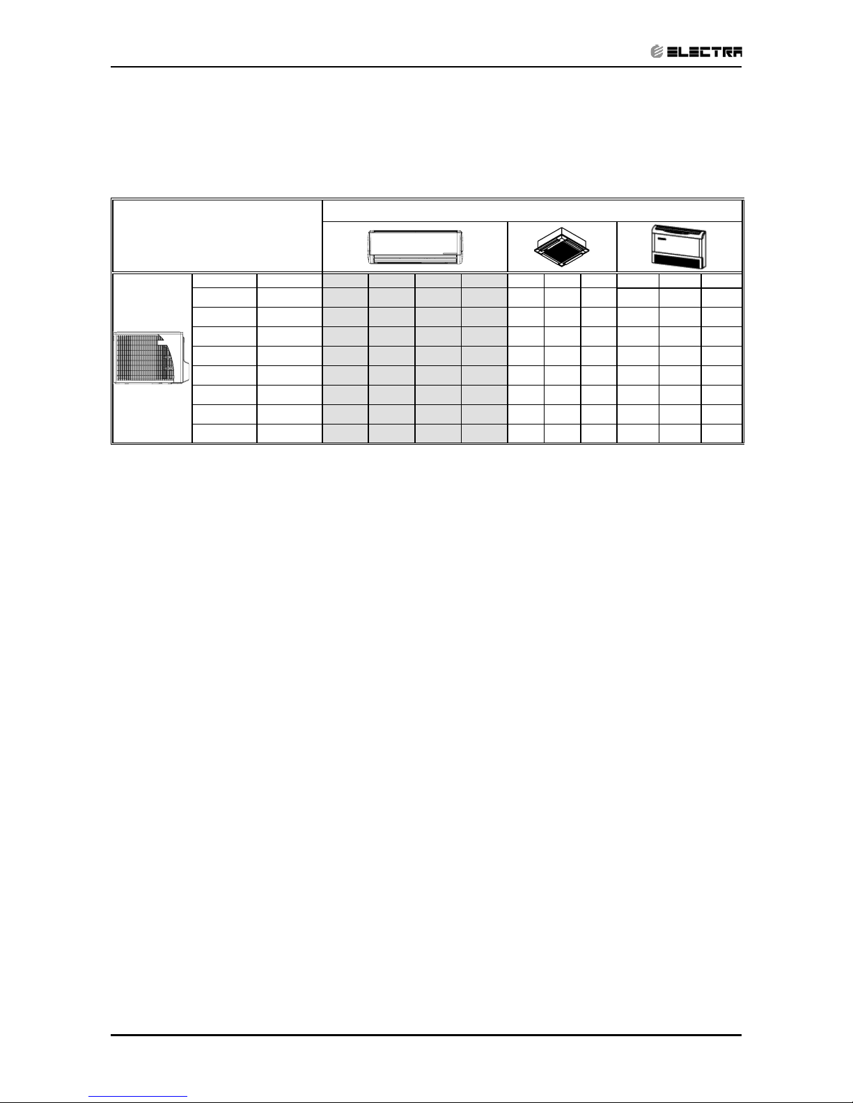
1.11 Matching Table
1.11.1 R410A
OUTDOOR UNITS
INDOOR UNITS
MODEL REFRIGER. LEX7 LEX9 LEX12 LEX14 K9 K11 K15 PXD9 PXD12 PXD15
ONG7 ST R410A √
ONG9 ST R410A √ √ √
ONG12 ST R410A √ √ √
ONG14 ST R410A √ √ √
ONG7 RC R410A √
ONG9 RC R410A √ √ √*
ONG12 RC R410A √ √
ONG14 RC R410A √* √
√* - The outdoor unit of this combination cannot be matched to other indoor units.
The above table lists outdoor units and LEX indoor units which can be matched together. In addition the
listed outdoor units can be matched with other types of indoor units such as cassettes, floor/ceiling.
For further information please refer to the relevant Service Manual.
Page 8

2-1
PRODUCT DATA SHEET
Revision Y06-01
Service Manual - LEX
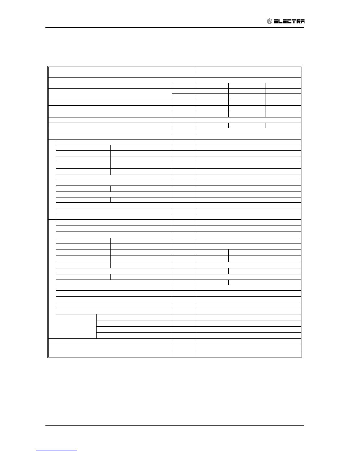
2. PRODUCT DATA SHEET
2.1 LEX 7 R410A Specification
Units Cooling Only
Btu/hr 7230
kW 2.12
kW 0.63
W/W 3.37
A
V/Ph/Hz
A2.8
A
A
H/M/L RPM
H/M/L m3/hr
Min-Max Pa
H/M/L dB(A)
H/M/L dB(A)
l/hr
mm
WxHxD mm
kg
WxHxD mm
kg
units
units
H/L RPM
H/L m3/hr
H/L dB(A) 60
H/L dB(A) 48
WxHxD mm
kg 31
WxHxD mm
kg 35
Units
units
kg/m 0.8kg/7.5m
4mL10m:+0g
10mL15m:+75g
In.(mm)
In.(mm)
m.
m.
kW
(1)Airflow in ducted units;at nominal external static pressure.
(2)Sound power in ducted units is measured at air discharge.
(3)Sound pressure level measured at 1-meter distance from unit.
(4)Rating conditions in accordance to ISO 5151 and ISO 13253 (for ducted units).
Refrigerant chargless distance 0.85kg/7.5m
4mL10m:+0g
10mL15m:+75g
3/8"(9.53)
Max.15
Max.7
Liquid line
Suction line
Max.tubing length
220-240V/Single/50Hz
15
10
Crossflow x 1
2.72.8
LEX-7
ONG-7
Flared
3.65
HeatingCooling
INDOOR
Connections
between units
OUTDOOR
Capacity
(4)
Power input
(4)
Air flow
Fan speeds
Fan type & quantity
Compressor type,model
Refrigerant control
A
7400
2.12 2.17
0.63 0.595
A
3.37
7230
9
945x395x655
45/41/39
30/27/25
0.7
16
810x210x285
48
795x290x610
11
60
0
380/320/280
860/760/660
870x285x355
13.5
36
680
Package dimensions
32
1/4"(6.35)
9 levels
3 levels
R410A
Capillary tube (with 026 restrictor)
Propeller(direct) x 1
Rotary,Toshiba PA82X1C-4DZDE
1660
Refrigerant type
Model Indoor Unit
Model Outdoor Unit
Installation Method of Pipe
Dimensions
Sound pressure level
(3)
Characteristics
EER (Cooling) or COP(Heating)
(4)
Weight
Condenstate drain tube I.D
Additional charge
Stacking height
Units per pallet
Packaged weight
Package dimensions
Sound power level
Stacking height
Units per pallet
Packaged weight
Weight
Fan type & quantity
Sound pressure level
(3)
Moisture removal
Air flow
(1)
Fan speeds
36
Power supply
Energy efficiency class
Sound power level
(2)
External static pressure
Circuit breaker rating
Starting current
Rated current
Dimensions
Heating elements (Option)
Others
Max.height difference
Remote control
0.3
Operation control type
Page 9
2-2
PRODUCT DATA SHEET
Revision Y06-01 Service Manual - LEX
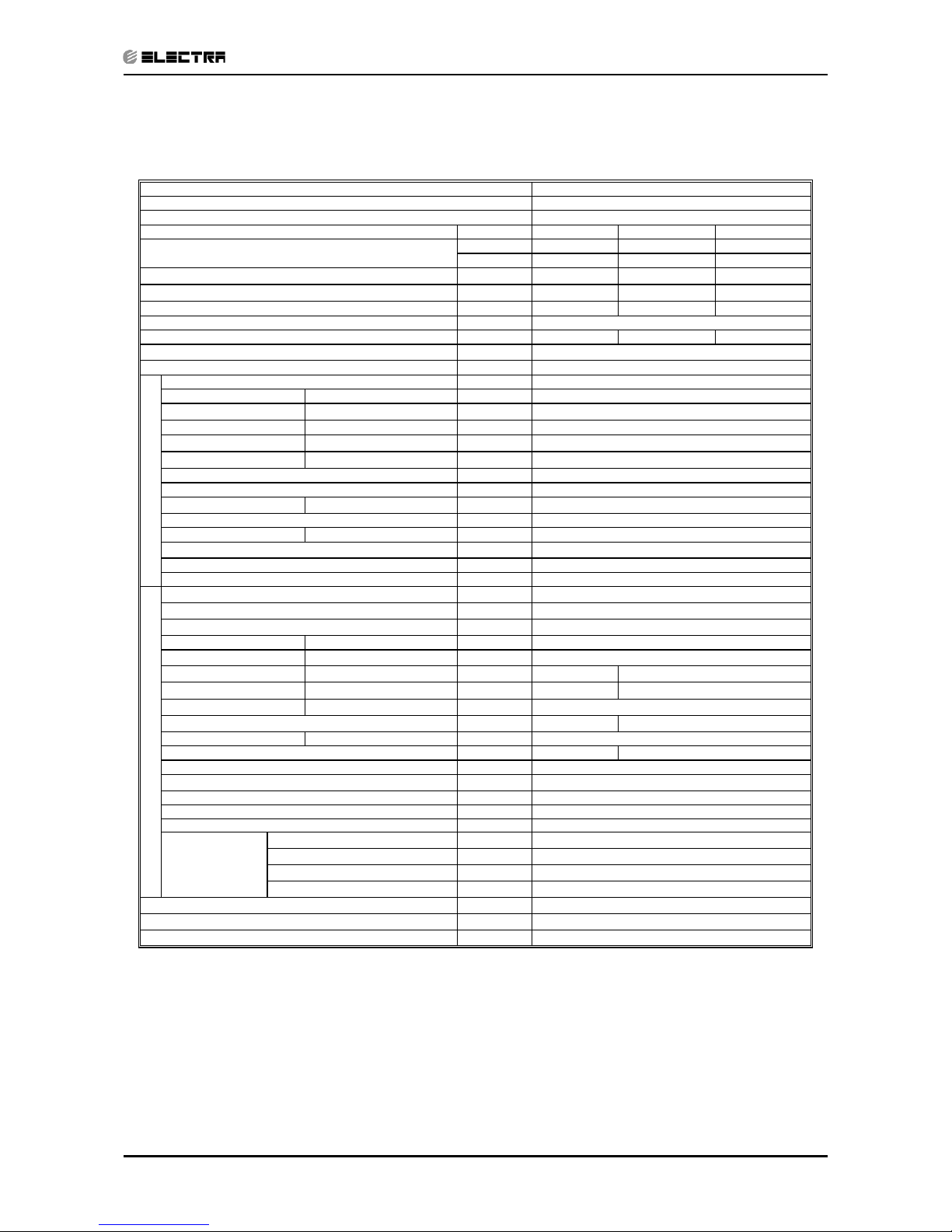
2.2 LEX 9 R410A Specification
Units Cooling Only
Btu/hr 9280
kW 2.72
kW 0.825
W/W 3.30
A
V/Ph/Hz
A3.7
A
A
H/M/L RPM
H/M/L m3/hr
Min-Max Pa
H/M/L dB(A)
H/M/L dB(A)
l/hr
mm
WxHxD mm
kg
WxHxD mm
kg
units
units
H/L RPM
H/L m3/hr
H/L dB(A) 61
H/L dB(A) 51
WxHxD mm
kg 34
WxHxD mm
kg 38
Units
units
kg(7.5mm)
In.(mm)
In.(mm)
m.
m.
kW
(1)Airflow in ducted units;at nominal external static pressure.
(2)Sound power in ducted units is measured at air discharge.
(3)Sound pressure level measured at 1-meter distance from unit.
(4)Rating conditions in accordance to ISO 5151 and ISO 13253 (for ducted units).
53
795x290x610
35
4mL10m: +0g; 10m L15m: +100g
13.5
36
1780
62
220-240V/Single/50Hz
18.7
10
Crossflow x 1
3.83.7
LEX-9
ONG-9
Flared
3.42
HeatingCooling
INDOOR
Connections
between units
OUTDOOR
Capacity
(4)
Power input
(4)
Air flow
Fan speeds
Fan type & quantity
Compressor type,model
Refrigerant control
B
9890
2.72 2.90
0.825 0.849
A
3.30
9280
960/860/760
9
945x395x655
49/46/44
35/31/28
0.9
16
810x210x285
11
870x285x355
1/4"(6.35)
9 levels
3 levels
R410A
Capillary tube (with 029 restrictor)
Propeller(direct) x 1
Rotary,Hitachi ASG108CV-B7AT
780
39
1.03
3/8"(9.53)
Max.15
Max.7
Model Indoor Unit
Model Outdoor Unit
Installation Method of Pipe
Dimensions
Sound pressure level
(3)
Package dimensions
Sound power level
Remote control
0.3
Characteristics
EER (Cooling) or COP(Heating)
(4)
Operation control type
Stacking height
Units per pallet
Packaged weight
Weight
Heating elements (Option)
Others
Refrigerant type
Liquid line
Suction line
Max.tubing length
Max.height difference
Refrigerant charge(stabdard connecting tubing length)
Additional charge
Stacking height
Units per pallet
Packaged weight
Weight
Dimensions
Condenstate drain tube I.D
Package dimensions
Fan type & quantity
Sound pressure level
(3)
Moisture removal
Air flow
(1)
Fan speeds
Power supply
Energy efficiency class
Sound power level
(2)
External static pressure
Circuit breaker rating
Starting current
Rated current
0
450/380/330
Page 10
2-3
PRODUCT DATA SHEET
Revision Y06-01
Service Manual - LEX
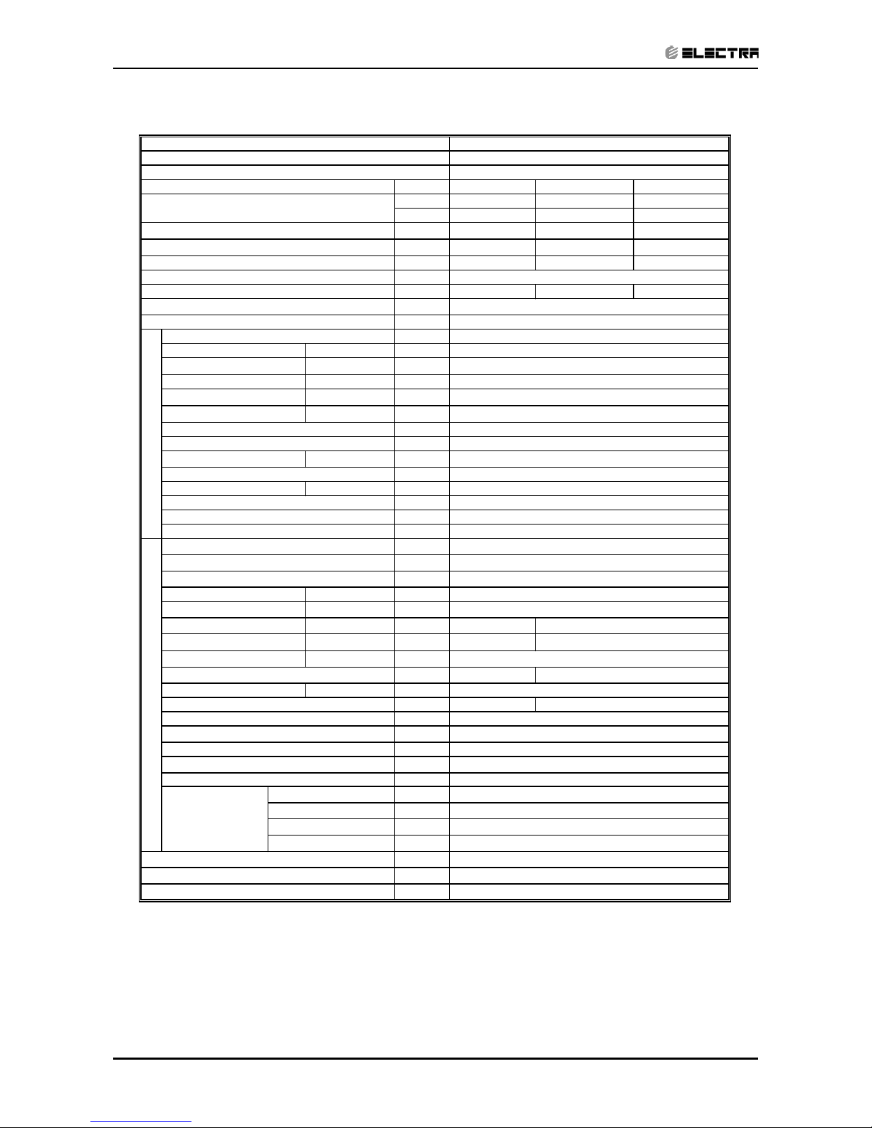
2.3 LEX 12 R410A Specification
Units Cooling Only
Btu/hr 12210
kW 3.58
kW 1.112
W/W 3.22
A
V/Ph/Hz
A5.0
A
A
H/M/L RPM
H/M/L m3/hr
Min-Max Pa
H/M/L dB(A)
H/M/L dB(A)
l/hr
mm
WxHxD mm
kg
WxHxD mm
kg
units
units
H/L RPM
H/L m3/hr
H/L dB(A) 61
H/L dB(A) 51
WxHxD mm
kg 35
WxHxD mm
kg 39
Units
units
kg(7.5mm)
In.(mm)
In.(mm)
m.
m.
kW
(1)Airflow in ducted units;at nominal external static pressure.
(2)Sound power in ducted units is measured at air discharge.
(3)Sound pressure level measured at 1-meter distance from unit.
(4)Rating conditions in accordance to ISO 5151 and ISO 13253 (for ducted units).
61
51
795x290x610
36
11.5
870x285x355
14
36
220-240V/Single/50Hz
25
15
Crossflow x 1
5.25.0
LEX-12
ONG-12
Flared
3.62
HeatingCooling
Fan speeds
Fan type & quantity
Compressor type,model
Refrigerant control
A
14160
3.58 4.15
1.112 1.145
A
3.22
12210
0
635/550/450
1230/1080/930
9
945x395x655
55/53/49
43/39/35
1.3
16
810x210x285
1/4"(6.35)
9 levels
3 levels
R410A
Capillary tube
Propeller(direct) x 1
Rotary,RN 145 VHSMT
1850
1.13
4mL10m: +0g; 10m L15m: +50g
Model Indoor Unit
Model Outdoor Unit
Installation Method of Pipe
Dimensions
Sound pressure level
(3)
Sound power level
INDOOR OUTDOOR
Capacity
(4)
Power input
(4)
Characteristics
EER (Cooling) or COP(Heating)
(4)
Operation control type
Stacking height
Units per pallet
Packaged weight
Weight
Package dimensions
Connections
between units
Air flow
Heating elements (Option)
Others
Refrigerant type
Liquid line
Suction line
Max.tubing length
Max.height difference
Refrigerant charge(stabdard connecting tubing length)
Additional charge
Stacking height
Units per pallet
Packaged weight
Weight
Rated current
Dimensions
Condenstate drain tube I.D
Package dimensions
Fan type & quantity
Sound pressure level
(3)
Moisture removal
Air flow
(1)
Fan speeds
810
40
Power supply
Energy efficiency class
Sound power level
(2)
External static pressure
Circuit breaker rating
Starting current
3/8"(9.53)
Max.15
Max.7
Remote control
0.3
Page 11
2-4
PRODUCT DATA SHEET
Revision Y06-01 Service Manual - LEX
2.4 LEX 14 R410A Specification
Units Cooling Only
Btu/hr 14400
kW 4.22
kW 1.31
W/W 3.22
A
V/Ph/Hz
A5.9
A
A
H/M/L RPM
H/M/L m3/hr
Min-Max Pa
H/M/L dB(A)
H/M/L dB(A)
l/hr
mm
WxHxD mm
kg
WxHxD mm
kg
units
units
H/L RPM
H/L m3/hr
H/L dB(A) 63
H/L dB(A) 53
WxHxD mm
kg 41.5
WxHxD mm
kg 45.5
Units
units
kg/m
In.(mm)
In.(mm)
m.
m.
kW
(1)Airflow in ducted units;at nominal external static pressure.
(2)Sound power in ducted units is measured at air discharge.
(3)Sound pressure level measured at 1-meter distance from unit.
(4)Rating conditions in accordance to ISO 5151 and ISO 13253 (for ducted units).
0.3
1/2"(12.7)
Max.15
Rated current
0
Remote control
Package dimensions
Weight
Power supply
Energy efficiency class
Sound power level
(2)
External static pressure
Circuit breaker rating
Starting current
Fan speeds
660/550/475
Dimensions
Condenstate drain tube I.D
Air flow
(1)
1280/1080/930
Others
Refrigerant type
Liquid line
Suction line
Max.tubing length
Max.height difference
Refrigerant chargless distance
Additional charge
Operation control type
Units per pallet
Packaged weight
Connections
between units
Heating elements (Option)
42.2
1/4"(6.35)
Characteristics
EER (Cooling) or COP(Heating)
(4)
Weight
INDOOR
Fan type & quantity
Sound pressure level
(3)
Moisture removal
Stacking height
46.5
Max.7
Model Indoor Unit
Model Outdoor Unit
Installation Method of Pipe
Dimensions
Sound pressure level
(3)
Package dimensions
Sound power level
OUTDOOR
Rotary,Sanyo C-RV168H1AB
920
53
795x290x610
9
945x395x655
56/51/46
46/41/36
1.5
16
810x210x285
11.5
870x285x355
Propeller(direct) x 1
C
15010
4.22 4.40
1.31 1.310
A
3.22
14400
Capacity
(4)
Power input
(4)
Air flow
Fan speeds
Fan type & quantity
Compressor type,model
Refrigerant control
Stacking height
Units per pallet
Packaged weight
LEX-14
ONG-14
Flared
3.36
HeatingCooling
220-240V/Single/50Hz
30
15
Crossflow x 1
5.95.9
1.38kg/7.5m
4mL10m: +0g 10m L15m: +120g
14
36
2160
63
9 levels
3 levels
R410A
Capillary tube
Page 12
3-1
RATING CONDITIONS
Revision Y06-01
Service Manual - LEX
3. RATING CONDITIONS
Standard conditions in accordance with ISO 5151, ISO 13253 (for ducted units)
and EN 14511.
Cooling:
Indoor: 27oC DB 19oC WB
Outdoor: 35 oC DB
Heating:
Indoor: 20oC DB
Outdoor: 7oC DB 6oC WB
3.1 Operating Limits
3.1.1 R410A
Indoor Outdoor
Cooling
Upper limit 32
o
C DB 23oC WB 46oC DB
Lower limit 21
o
C DB 15oC WB 10oC DB
Heating
Upper limit 27
o
C DB 24oC DB 18oC WB
Lower limit 10
o
C DB -9oC DB -10oC WB
Voltage 1PH 198 ÷ 264 V
Page 13
4-1
OUTLINE DIMENSIONS
Revision Y06-01Service Manual - LEX
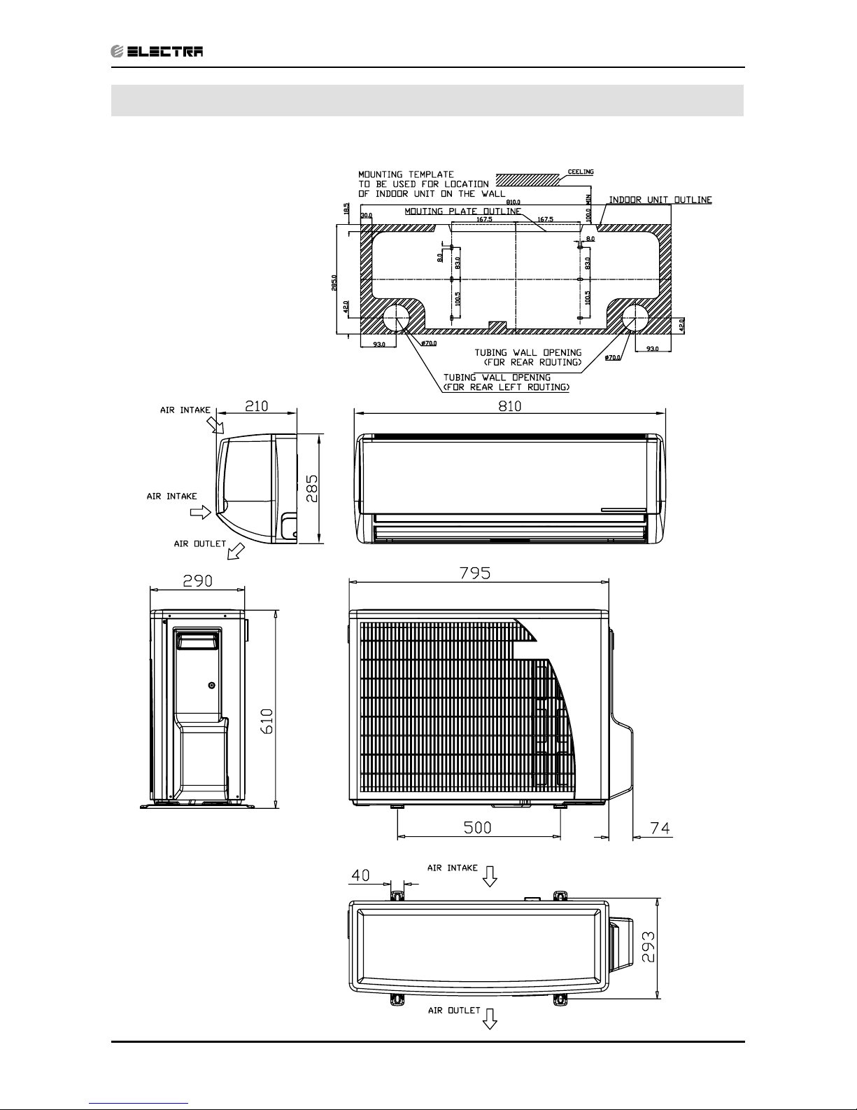
4. OUTLINE DIMENSIONS
4.1 LEX 7, 9, 12, 14 / ONG3 -7, 9, 12, 14
Page 14
5-1
PERFORMANCE DATA & PRESSURE CURVES
Revision Y06-01Service Manual - LEX
5. PERFORMANCE DATA & PRESSURE CURVES
5.1 LEX7 / ONG7 R410A
5.1.1 Cooling Mode at 7.5m Tubing Connection.
230V : Indoor Fan at High Speed.
LEGEND
TC – Total Cooling Capacity, kW
SC – Sensible Capacity, kW
PI – Power Input, kW
WB – Wet Bulb Temp., (
o
C)
DB – Dry Bulb Temp., (
o
C)
ID – Indoor
OD – Outdoor
(1) Marked area is below standard operating limits. For operating in low ambient
conditions, refer to Optional Accessories (Chapter 15).
Entering Air WB/DB ID Coil(oC)
15/21 17/24 19/27 21/29 23/32
TC
2.23 2.31 2.37 2.42 2.46
15
(1)
SC
1.59 1.65 1.72 1.76 1.79
PI
0.45 0.45 0.45 0.45 0.45
TC
2.16 2.28 2.35 2.41 2.46
20
(1)
SC
1.55 1.64 1.71 1.76 1.79
PI
0.49 0.49 0.49 0.49 0.49
TC
2.05 2.21 2.32 2.39 2.45
25 SC
1.52 1.61 1.70 1.74 1.78
PI
0.52 0.53 0.53 0.53 0.54
TC
1.91 2.08 2.25 2.33 2.40
30 SC
1.47 1.56 1.66 1.71 1.74
PI
0.57 0.57 0.58 0.58 0.59
TC
1.77 1.92
2.12
2.23 2.33
35 SC
1.40 1.50
1.62
1.67 1.70
PI
0.61 0.62
0.63
0.63 0.64
TC
1.61 1.75 1.91 2.09 2.20
40 SC
1.32 1.42 1.53 1.58 1.61
PI
0.66 0.67 0.68 0.69 0.69
TC
1.40 1.53 1.68 1.86 2.00
46 SC
1.21 1.30 1.40 1.45 1.48
PI
0.72 0.73 0.75 0.76 0.77
Entering Air DB
OD Coil(
o
C)
Data
Page 15
5-2
PERFORMANCE DATA & PRESSURE CURVES
Revision Y06-01 Service Manual - LEX
5.1.2 Heating Mode at 7.5m Tubing Connection.
230V : Indoor Fan at High Speed.
* the above chart includes the weighted deicing infleuence.
LEGEND
TH – Total Heating Capacity, kW
PI – Power Input, kW
WB – Wet Bulb Temp., (oC)
DB – Dry Bulb Temp., (oC)
ID – Indoor
OD – Outdoor
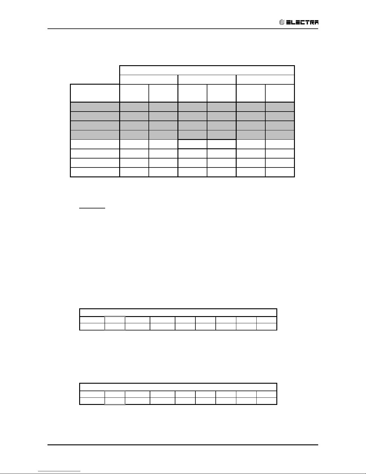
5.2 Capacity Correction Factor Due to Tubing Length
5.2.1 Cooling
TOTAL TUBING LENGTH (One Way)
3m
7.5m
10m 15m 20m 25m 30m 40m 50m
1.02
1
0.961 0.949 --- --- --- --- ---
* Minimum recommended tubing length between indoor and outdoor units is 3m.
5.2.2 Heating
TOTAL TUBING LENGTH (One Way)
3m
7.5m
10m 15m 20m 25m 30m 40m 50m
1.05
1
0.975 0.965 --- --- --- --- ---
* Minimum recommended tubing length between indoor and outdoor units is 3m.
15 20 25
ENTERING WB
OD COIL(
o
C)
TH Pl TH Pl TH Pl
-10 1.13 0.48 1.09 0.51 1.04 0.53
-7 1.21 0.49 1.17 0.51 1.13 0.54
-2 1.29 0.49 1.25 0.52 1.20 0.55
2 1.57 0.52 1.51 0.55 1.44 0.58
62.210.56
2.15 0.60
2.07 0.63
10 2.41 0.59 2.34 0.63 2.28 0.67
15 2.60 0.61 2.54 0.66 2.47 0.70
20 2.74 0.63 2.68 0.68 2.60 0.74
ENTERING AIR DB ID COIL(
O
C)
Page 16

5-3
PERFORMANCE DATA & PRESSURE CURVES
Revision Y06-01Service Manual - LEX
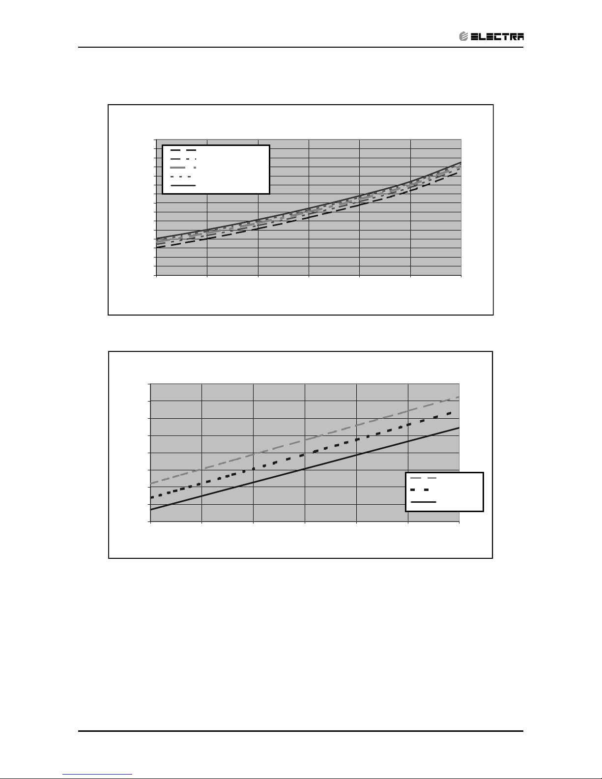
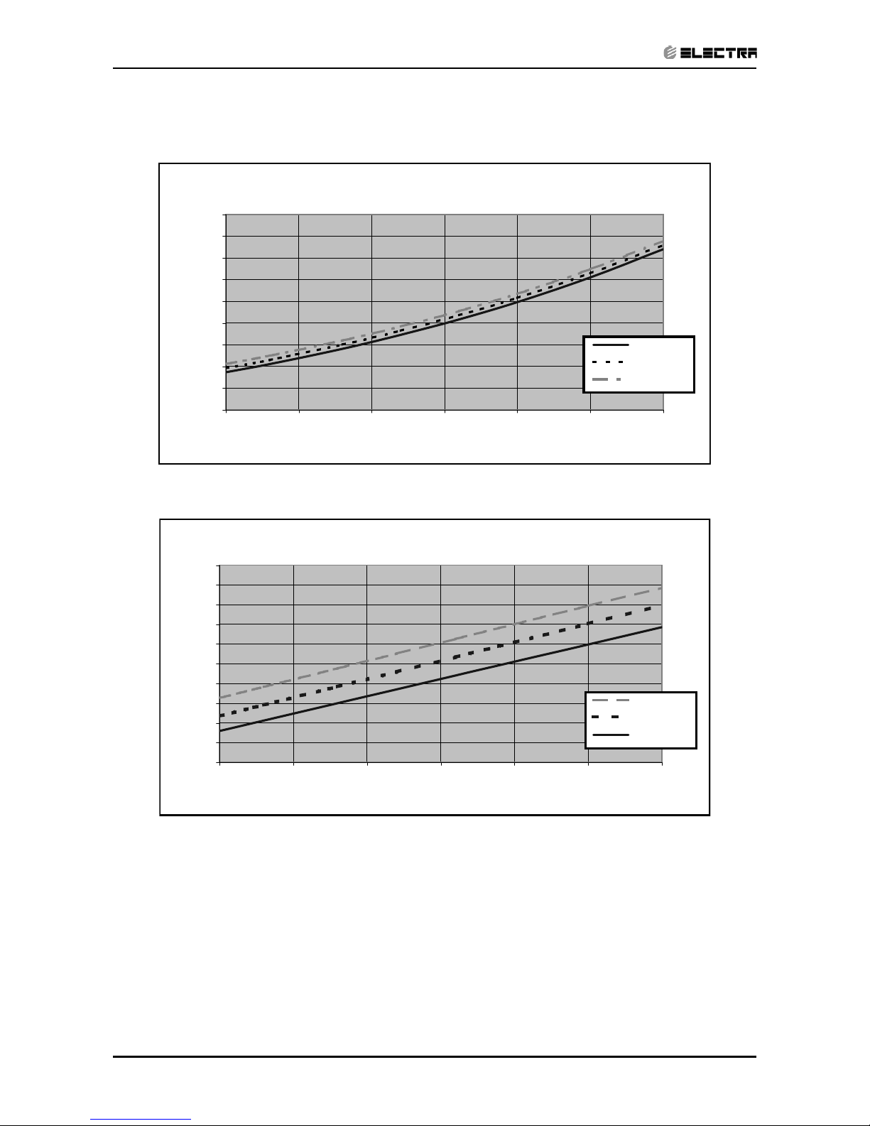
5.3 Pressure Curves.
5.3.1 Cooling.
Suction Pressure VS.Outdoor Temp
5.0
6.0
7.0
8.0
9.0
10.0
11.0
12.0
13.0
14.0
15 20 25 30 35 40 46
Outdoor Temp.(DB oC )
Suction Pressure (Bar[g])
15/21(WB/DB ºC)
17/24(WB/DB ºC)
19/27(WB/DB ºC)
21/29(WB/DB ºC)
23/32(WB/DB ºC)
Discharge Pressure VS.Outdoor Temp
10
12
14
16
18
20
22
24
26
28
30
32
34
36
38
40
15 20 25 30 35 40 46
Outdoor Temp.(DB oC )
Discharge Pressure (Bar[g])
15/21(WB/DB ºC)
17/24(WB/DB ºC)
19/27(WB/DB ºC)
21/29(WB/DB ºC)
23/32(WB/DB ºC)
Page 17
5-4
PERFORMANCE DATA & PRESSURE CURVES
Revision Y06-01 Service Manual - LEX
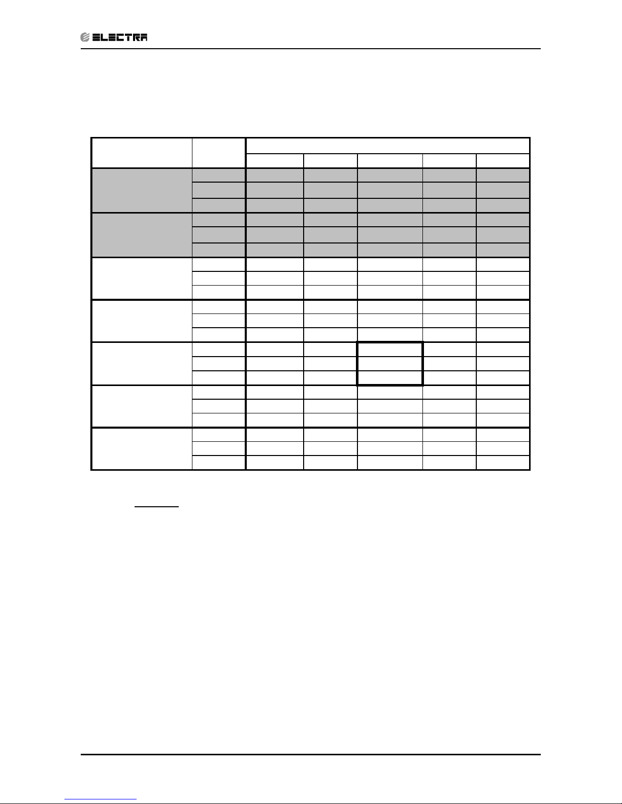
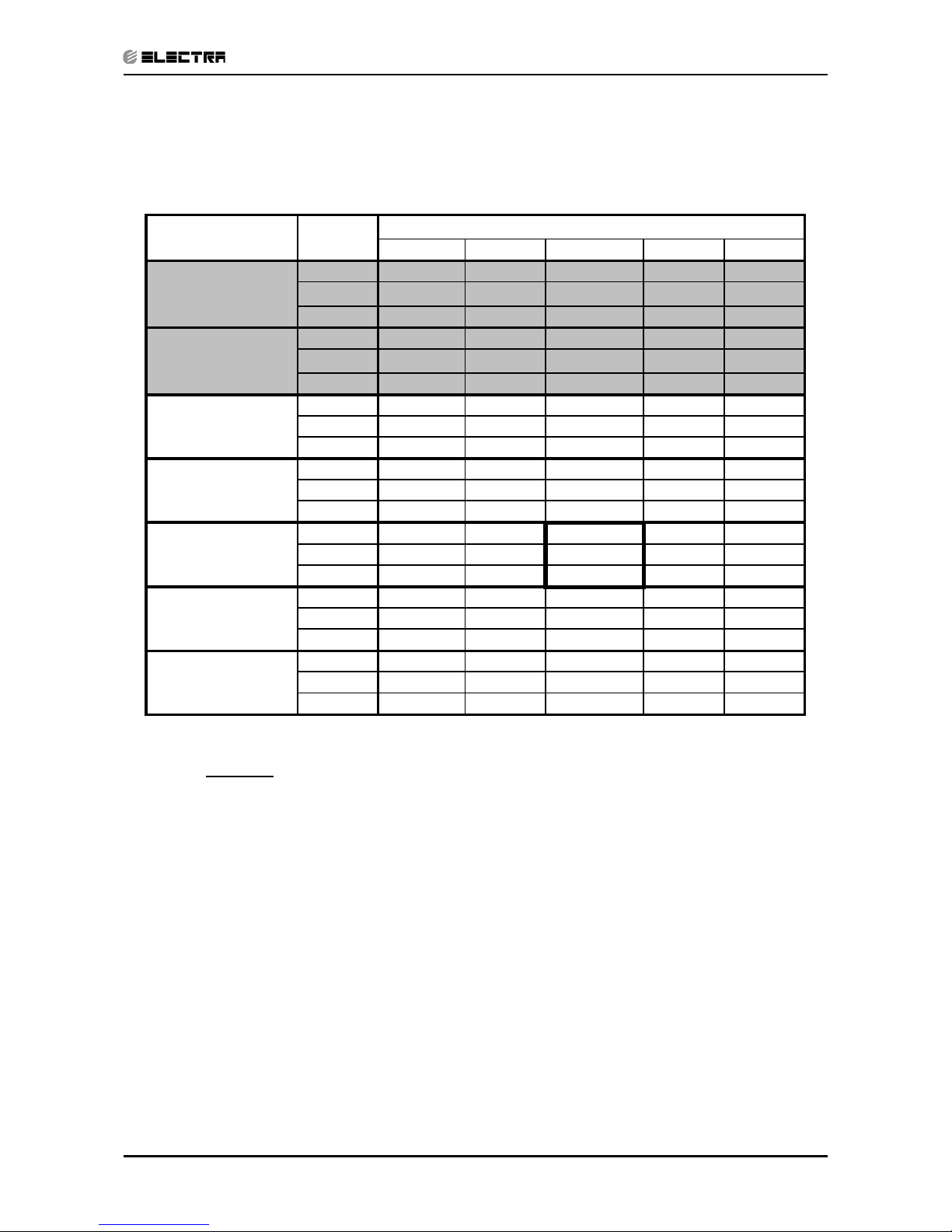
5.3.2 Heating.
Discharge Pressure VS.Outdoor Temp
10
12
14
16
18
20
22
24
26
28
30
32
34
36
38
40
15 20 25 30 35 40 46
Outdoor Temp.(DB oC )
Discharge Pressure (Bar[g])
15/21(WB/DB ºC)
17/24(WB/DB ºC)
19/27(WB/DB ºC)
21/29(WB/DB ºC)
23/32(WB/DB ºC)
Discharge Pressure VS.Outdoor Temp
16
18
20
22
24
26
28
30
32
-10 -5 0 5 10 15 20
Outdoor Temp.( WB oC )
Discharge Pressure(Bar[g])
25 DB (ºC)
20 DB (ºC)
15 DB (ºC)
Page 18
5-5
PERFORMANCE DATA & PRESSURE CURVES
Revision Y06-01Service Manual - LEX
5.4 LEX9 / ONG9 R410A
5.4.1 Cooling Mode at 7.5m Tubing Connection.
230V : Indoor Fan at High Speed.
LEGEND
TC – Total Cooling Capacity, kW
SC – Sensible Capacity, kW
PI – Power Input, kW
WB – Wet Bulb Temp., (oC)
DB – Dry Bulb Temp., (oC)
ID – Indoor
OD – Outdoor
(1) Marked area is below standard operating limits. For operating in low ambient
conditions, refer to Optional Accessories (Chapter 15).
Entering Air WB/DB ID Coil(oC)
15/21 17/24 19/27 21/29 23/32
TC
2.87 2.97 3.04 3.11 3.16
15
(1)
SC
1.93 2.01 2.09 2.14 2.18
PI
0.58 0.59 0.59 0.59 0.59
TC
2.77 2.92 3.02 3.09 3.15
20
(1)
SC
1.89 1.99 2.08 2.14 2.18
PI
0.64 0.64 0.64 0.64 0.64
TC
2.62 2.83 2.98 3.07 3.14
25 SC
1.84 1.95 2.06 2.12 2.16
PI
0.69 0.69 0.70 0.70 0.70
TC
2.45 2.67 2.89 2.99 3.08
30 SC
1.78 1.90 2.02 2.08 2.11
PI
0.74 0.75 0.76 0.76 0.77
TC
2.27 2.47
2.72
2.86 2.99
35 SC
1.70 1.82
1.97
2.03 2.07
PI
0.80 0.81
0.83
0.83 0.84
TC
2.07 2.25 2.45 2.68 2.82
40 SC
1.60 1.72 1.86 1.92 1.96
PI
0.86 0.87 0.89 0.90 0.91
TC
1.79 1.96 2.16 2.38 2.57
46 SC
1.47 1.58 1.70 1.76 1.80
PI
0.94 0.96 0.98 0.99 1.00
Entering Air DB
OD Coil(
o
C)
Data
Page 19
5-6
PERFORMANCE DATA & PRESSURE CURVES
Revision Y06-01 Service Manual - LEX
5.4.2 Heating Mode at 7.5m Tubing Connection.
230V : Indoor Fan at High Speed.
* the above chart includes the weighted deicing infleuence.
LEGEND
TH – Total Heating Capacity, kW
PI – Power Input, kW
WB – Wet Bulb Temp., (oC)
DB – Dry Bulb Temp., (oC)
ID – Indoor
OD – Outdoor
5.5 Capacity Correction Factor Due to Tubing Length
5.5.1 Cooling
TOTAL TUBING LENGTH (One Way)
3m
7.5m
10m 15m 20m 25m 30m 40m 50m
1.02
1
0.961 0.950 --- --- --- --- ---
* Minimum recommended tubing length between indoor and outdoor units is 3m.
5.5.2 Heating
TOTAL TUBING LENGTH (One Way)
3m
7.5m
10m 15m 20m 25m 30m 40m 50m
1.05
1
0.975 0.961 --- --- --- --- ---
* Minimum recommended tubing length between indoor and outdoor units is 3m.
15 20 25
ENTERING WB
OD COIL(
o
C)
TH Pl TH Pl TH Pl
-10 1.52 0.68 1.46 0.72 1.41 0.76
-7 1.64 0.70 1.58 0.73 1.52 0.77
-2 1.74 0.70 1.68 0.75 1.62 0.79
2 2.12 0.74 2.03 0.79 1.94 0.83
6 2.99 0.79
2.90 0.85
2.80 0.90
10 3.25 0.84 3.16 0.90 3.07 0.96
15 3.51 0.87 3.42 0.94 3.34 1.00
20 3.70 0.90 3.61 0.98 3.51 1.05
ENTERING AIR DB ID COIL(
O
C)
Page 20
5-7
PERFORMANCE DATA & PRESSURE CURVES
Revision Y06-01Service Manual - LEX
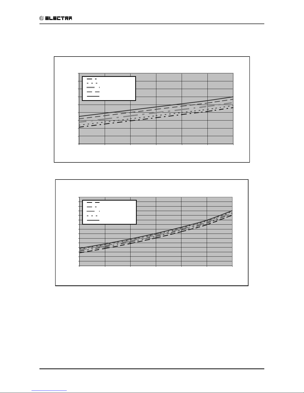
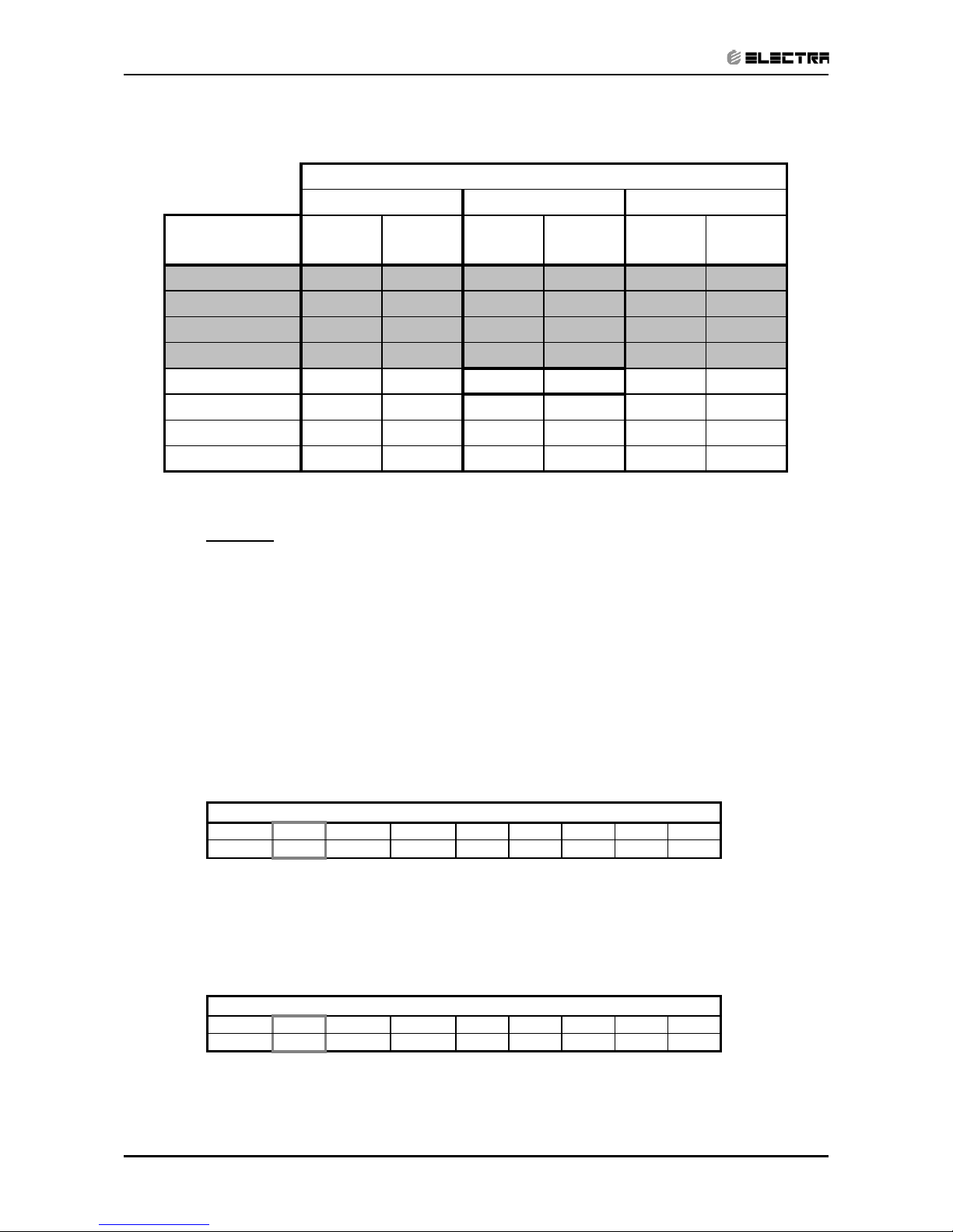
5.6 Pressure Curves.
5.6.1 Cooling.
Suction Pressure VS.Outdoor Temp
5.0
6.0
7.0
8.0
9.0
10.0
11.0
12.0
13.0
14.0
15 20 25 30 35 40 46
Outdoor Temp.(DB oC )
Suction Pressure (Bar[g])
15/21(WB/DB ºC)
17/24(WB/DB ºC)
19/27(WB/DB ºC)
21/29(WB/DB ºC)
23/32(WB/DB ºC)
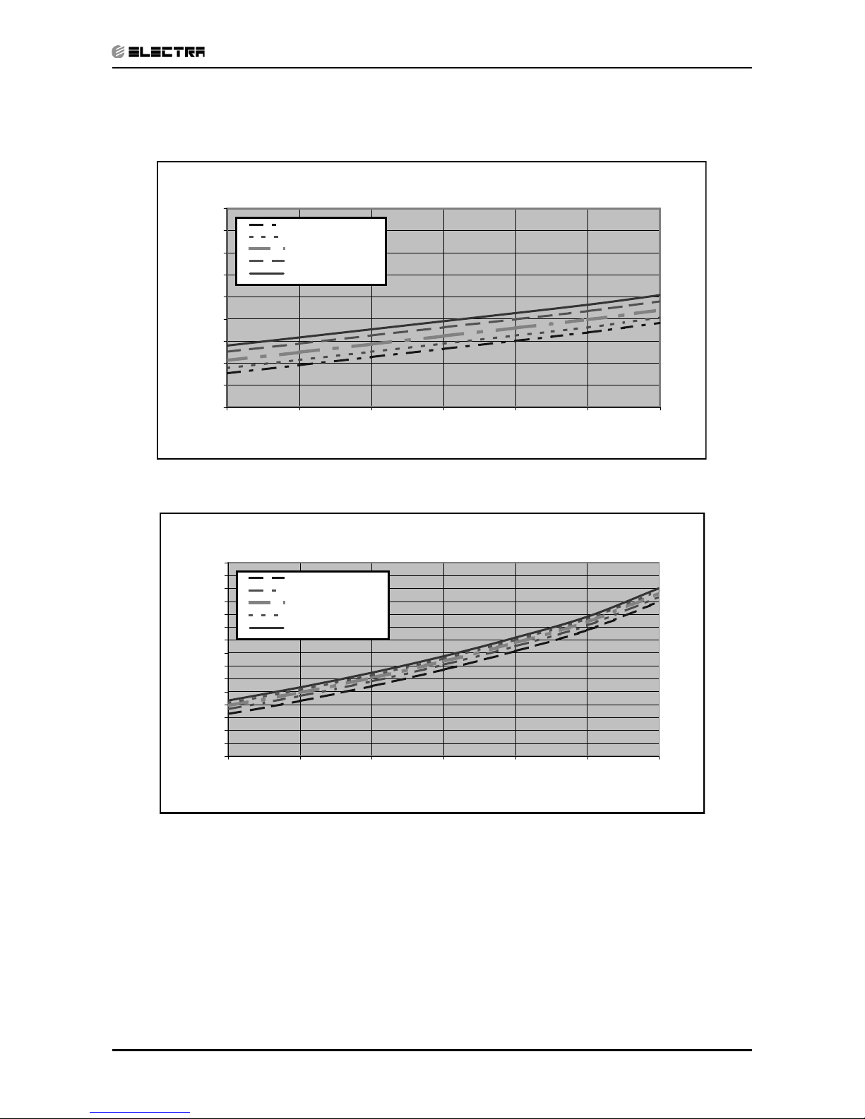
Discharge Pressure VS.Outdoor Temp
10
12
14
16
18
20
22
24
26
28
30
32
34
36
38
40
15 20 25 30 35 40 46
Outdoor Temp.(DB oC )
Discharge Pressure (Bar[g])
15/21(WB/DB ºC)
17/24(WB/DB ºC)
19/27(WB/DB ºC)
21/29(WB/DB ºC)
23/32(WB/DB ºC)
Page 21
5-8
PERFORMANCE DATA & PRESSURE CURVES
Revision Y06-01 Service Manual - LEX
5.6.2 Heating.
Suction Pressure VS.Outdoor Temp
3.0
4.0
5.0
6.0
7.0
8.0
9.0
10.0
11.0
12.0
-10 -5 0 5 10 15 20
Outdoor Temp.( WB oC )
Suction Pressure(Bar[g])
15 DB (ºC)
20 DB (ºC)
25 DB (ºC)
Discharge Pressure VS.Outdoor Temp
16
18
20
22
24
26
28
30
32
34
36
-10 -5 0 5 10 15 20
Outdoor Temp.( WB oC )
Discharge Pressure(Bar[g])
25 DB (ºC)
20 DB (ºC)
15 DB (ºC)
Page 22
5-9
PERFORMANCE DATA & PRESSURE CURVES
Revision Y06-01Service Manual - LEX
5.7 LEX12 / ONG12 R410A
5.7.1 Cooling Mode at 7.5m Tubing Connection.
230V : Indoor Fan at High Speed.
LEGEND
TC – Total Cooling Capacity, kW
SC – Sensible Capacity, kW
PI – Power Input, kW
WB – Wet Bulb Temp., (
o
C)
DB – Dry Bulb Temp., (oC)
ID – Indoor
OD – Outdoor
(1) Marked area is below standard operating limits. For operating in low ambient
conditions, refer to Optional Accessories (Chapter 15).
Entering Air WB/DB ID Coil(oC)
15/21 17/24 19/27 21/29 23/32
TC
3.77 3.91 4.00 4.10 4.16
15
(1)
SC
2.57 2.68 2.78 2.85 2.90
PI
0.79 0.79 0.79 0.79 0.80
TC
3.65 3.85 3.97 4.06 4.15
20
(1)
SC
2.51 2.65 2.76 2.84 2.89
PI
0.86 0.86 0.86 0.87 0.87
TC
3.45 3.73 3.92 4.04 4.14
25 SC
2.45 2.60 2.74 2.82 2.87
PI
0.92 0.93 0.94 0.94 0.95
TC
3.23 3.52 3.80 3.93 4.05
30 SC
2.37 2.52 2.68 2.76 2.81
PI
1.00 1.01 1.02 1.03 1.04
TC
2.99 3.25
3.58
3.76 3.94
35 SC
2.26 2.42
2.62
2.70 2.75
PI
1.08 1.09
1.11
1.12 1.13
TC
2.72 2.96 3.23 3.53 3.71
40 SC
2.13 2.29 2.48 2.56 2.61
PI
1.16 1.18 1.20 1.21 1.23
TC
2.36 2.58 2.84 3.13 3.38
46 SC
1.96 2.10 2.26 2.34 2.39
PI
1.27 1.29 1.32 1.34 1.35
Entering Air DB
OD Coil(
o
C)
Data
Page 23
5-10
PERFORMANCE DATA & PRESSURE CURVES
Revision Y06-01 Service Manual - LEX
5.7.2 Heating Mode at 7.5m Tubing Connection.
230V : Indoor Fan at High Speed.
* the above chart includes the weighted deicing infleuence.
LEGEND
TH – Total Heating Capacity, kW
PI – Power Input, kW
WB – Wet Bulb Temp., (oC)
DB – Dry Bulb Temp., (oC)
ID – Indoor
OD – Outdoor
5.8 Capacity Correction Factor Due to Tubing Length
5.8.1 Cooling
TOTAL TUBING LENGTH (One Way)
3m
7.5m
10m 15m 20m 25m 30m 40m 50m
1.02
1
0.961 0.948 --- --- --- --- ---
* Minimum recommended tubing length between indoor and outdoor units is 3m.
5.8.2 Heating
TOTAL TUBING LENGTH (One Way)
3m
7.5m
10m 15m 20m 25m 30m 40m 50m
1.05
1
0.975 0.963 --- --- --- --- ---
* Minimum recommended tubing length between indoor and outdoor units is 3m.
15 20 25
ENTERING WB
OD COIL(
o
C)
TH Pl TH Pl TH Pl
-10 2.18 0.92 2.10 0.98 2.01 1.02
-7 2.34 0.94 2.26 0.99 2.18 1.04
-2 2.49 0.95 2.41 1.01 2.32 1.06
2 3.03 1.00 2.91 1.06 2.78 1.12
6 4.27 1.07
4.15 1.15
4.00 1.22
10 4.65 1.13 4.52 1.21 4.40 1.29
15 5.02 1.18 4.90 1.27 4.77 1.35
20 5.29 1.21 5.17 1.32 5.02 1.42
ENTERING AIR DB ID COIL(
O
C)
Page 24
5-11
PERFORMANCE DATA & PRESSURE CURVES
Revision Y06-01Service Manual - LEX
5.9 Pressure Curves.
5.9.1 Cooling.
Suction Pressure VS.Outdoor Temp
5.0
6.0
7.0
8.0
9.0
10.0
11.0
12.0
13.0
14.0
15 20 25 30 35 40 46
Outdoor Temp.(DB oC )
Suction Pressure (Bar[g])
15/21(WB/DB ºC)
17/24(WB/DB ºC)
19/27(WB/DB ºC)
21/29(WB/DB ºC)
23/32(WB/DB ºC)
Discharge Pressure VS.Outdoor Temp
10
12
14
16
18
20
22
24
26
28
30
32
34
36
38
40
15 20 25 30 35 40 46
Outdoor Temp.(DB oC )
Discharge Pressure (Bar[g])
15/21(WB/DB ºC)
17/24(WB/DB ºC)
19/27(WB/DB ºC)
21/29(WB/DB ºC)
23/32(WB/DB ºC)
Page 25
5-12
PERFORMANCE DATA & PRESSURE CURVES
Revision Y06-01 Service Manual - LEX
5.9.2 Heating.
Suction Pressure VS.Outdoor Temp
3.0
4.0
5.0
6.0
7.0
8.0
9.0
10.0
11.0
-10 -5 0 5 10 15 20
Outdoor Temp.( WB oC )
Suction Pressure(Bar[g])
15 DB (ºC)
20 DB (ºC)
25 DB (ºC)
Discharge Pressure VS.Outdoor Temp
16
18
20
22
24
26
28
30
32
34
36
38
-10 -5 0 5 10 15 20
Outdoor Temp.( WB oC )
Discharge Pressure(Bar[g])
25 DB (ºC)
20 DB (ºC)
15 DB (ºC)
Page 26

5-13
PERFORMANCE DATA & PRESSURE CURVES
Revision Y06-01Service Manual - LEX
5.10 LEX14 / ONG14 R410A
5.10.1 Cooling Mode at 7.5m Tubing Connection.
230V : Indoor Fan at High Speed.
LEGEND
TC – Total Cooling Capacity, kW
SC – Sensible Capacity, kW
PI – Power Input, kW
WB – Wet Bulb Temp., (
o
C)
DB – Dry Bulb Temp., (
o
C)
ID – Indoor
OD – Outdoor
(1) Marked area is below standard operating limits. For operating in low ambient
conditions, refer to Optional Accessories (Chapter 15).
Entering Air WB/DB ID Coil(oC)
15/21 17/24 19/27 21/29 23/32
TC
4.45 4.61 4.72 4.83 4.90
15
(1)
SC
2.89 3.01 3.13 3.21 3.27
PI
0.93 0.93 0.93 0.93 0.94
TC
4.30 4.54 4.68 4.79 4.89
20
(1)
SC
2.83 2.98 3.11 3.20 3.26
PI
1.01 1.01 1.02 1.02 1.02
TC
4.07 4.40 4.62 4.76 4.88
25 SC
2.76 2.93 3.09 3.18 3.23
PI
1.09 1.10 1.10 1.11 1.12
TC
3.81 4.15 4.48 4.64 4.78
30 SC
2.67 2.84 3.02 3.11 3.17
PI
1.18 1.19 1.20 1.21 1.22
TC
3.53 3.83
4.22
4.43 4.64
35 SC
2.54 2.72
2.95
3.04 3.09
PI
1.27 1.29
1.31
1.32 1.33
TC
3.21 3.49 3.81 4.16 4.38
40 SC
2.39 2.58 2.79 2.88 2.94
PI
1.37 1.39 1.41 1.43 1.44
TC
2.78 3.04 3.34 3.69 3.98
46 SC
2.21 2.36 2.54 2.63 2.69
PI
1.49 1.52 1.55 1.57 1.59
Entering Air DB
OD Coil(
o
C)
Data
Page 27

5-14
PERFORMANCE DATA & PRESSURE CURVES
Revision Y06-01 Service Manual - LEX
5.10.2 Heating Mode at 7.5m Tubing Connection.
230V : Indoor Fan at High Speed.
* the above chart includes the weighted deicing infleuence.
LEGEND
TH – Total Heating Capacity, kW
PI – Power Input, kW
WB – Wet Bulb Temp., (oC)
DB – Dry Bulb Temp., (oC)
ID – Indoor
OD – Outdoor
5.11 Capacity Correction Factor Due to Tubing Length
5.11.1 Cooling
TOTAL TUBING LENGTH (One Way)
3m
7.5m
10m 15m 20m 25m 30m 40m 50m
1.02
1
0.984 0.946 --- --- --- --- ---
* Minimum recommended tubing length between indoor and outdoor units is 3m.
5.11.2 Heating
TOTAL TUBING LENGTH (One Way)
3m
7.5m
10m 15m 20m 25m 30m 40m 50m
1.03
1
0.995 0.971 --- --- --- --- ---
* Minimum recommended tubing length between indoor and outdoor units is 3m.
15 20 25
ENTERING WB
OD COIL(
o
C)
TH Pl TH Pl TH Pl
-10 2.31 0.90 2.22 0.96 2.13 1.01
-7 2.49 0.93 2.40 0.98 2.31 1.03
-2 2.64 0.94 2.55 1.00 2.46 1.05
2 3.21 0.98 3.08 1.05 2.95 1.11
64.531.06
4.40 1.13
4.25 1.20
10 4.93 1.12 4.80 1.19 4.66 1.28
15 5.32 1.16 5.19 1.26 5.06 1.33
20 5.61 1.20 5.48 1.30 5.32 1.40
ENTERING AIR DB ID COIL(
O
C)
Page 28
5-15
PERFORMANCE DATA & PRESSURE CURVES
Revision Y06-01Service Manual - LEX
5.12 Pressure Curves.
5.12.1 Cooling.
Suction Pressure VS.Outdoor Temp
5.0
6.0
7.0
8.0
9.0
10.0
11.0
12.0
13.0
14.0
15 20 25 30 35 40 46
Outdoor Temp.(DB oC )
Suction Pressure (Bar[g])
15/21(WB/DB ºC)
17/24(WB/DB ºC)
19/27(WB/DB ºC)
21/29(WB/DB ºC)
23/32(WB/DB ºC)
Discharge Pressure VS.Outdoor Temp
10
12
14
16
18
20
22
24
26
28
30
32
34
36
38
40
15 20 25 30 35 40 46
Outdoor Temp.(DB oC )
Discharge Pressure (Bar[g])
15/21(WB/DB ºC)
17/24(WB/DB ºC)
19/27(WB/DB ºC)
21/29(WB/DB ºC)
23/32(WB/DB ºC)
Page 29
5-16
PERFORMANCE DATA & PRESSURE CURVES
Revision Y06-01 Service Manual - LEX
5.12.2 Heating.
Suction Pressure VS.Outdoor Temp
3.0
4.0
5.0
6.0
7.0
8.0
9.0
10.0
11.0
-10 -5 0 5 10 15 20
Outdoor Temp.( WB oC )
Suction Pressure(Bar[g])
15 DB (ºC)
20 DB (ºC)
25 DB (ºC)
Discharge Pressure VS.Outdoor Temp
16
18
20
22
24
26
28
30
32
34
36
38
-10 -5 0 5 10 15 20
Outdoor Temp.( WB oC )
Discharge Pressure(Bar[g])
25 DB (ºC)
20 DB (ºC)
15 DB (ºC)
Page 30
6-1
SOUND LEVEL CHARACTERISTICS
Revision Y06-01Service Manual - LEX
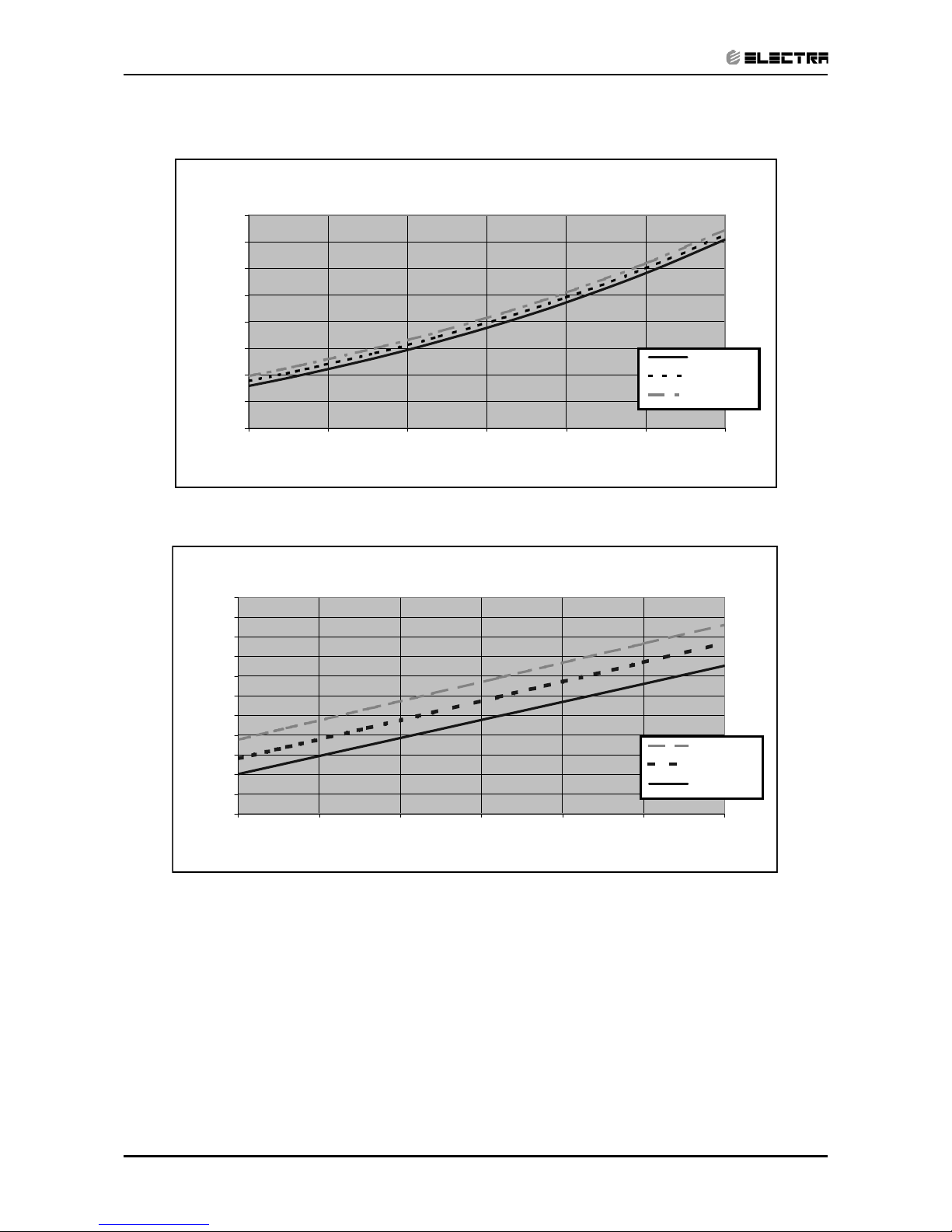
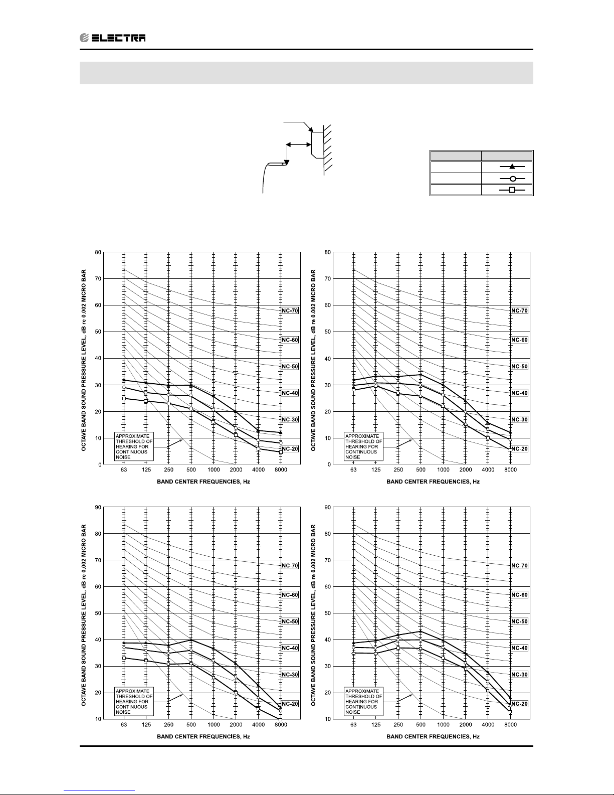
6. SOUND LEVEL CHARACTERISTICS
6.1 Sound Pressure Level
6.2 Sound Pressure Level Spectrum
(Measured as Figure 1)
FAN SPEED LINE
HI
ME
LO
0.8m
Mic.
Unit
Wall
LEX 12 RC LEX 14 RC
LEX 7 RC LEX 9 RC
Figure 1
Page 31

6-2
SOUND LEVEL CHARACTERISTICS
Revision Y06-01 Service Manual - LEX
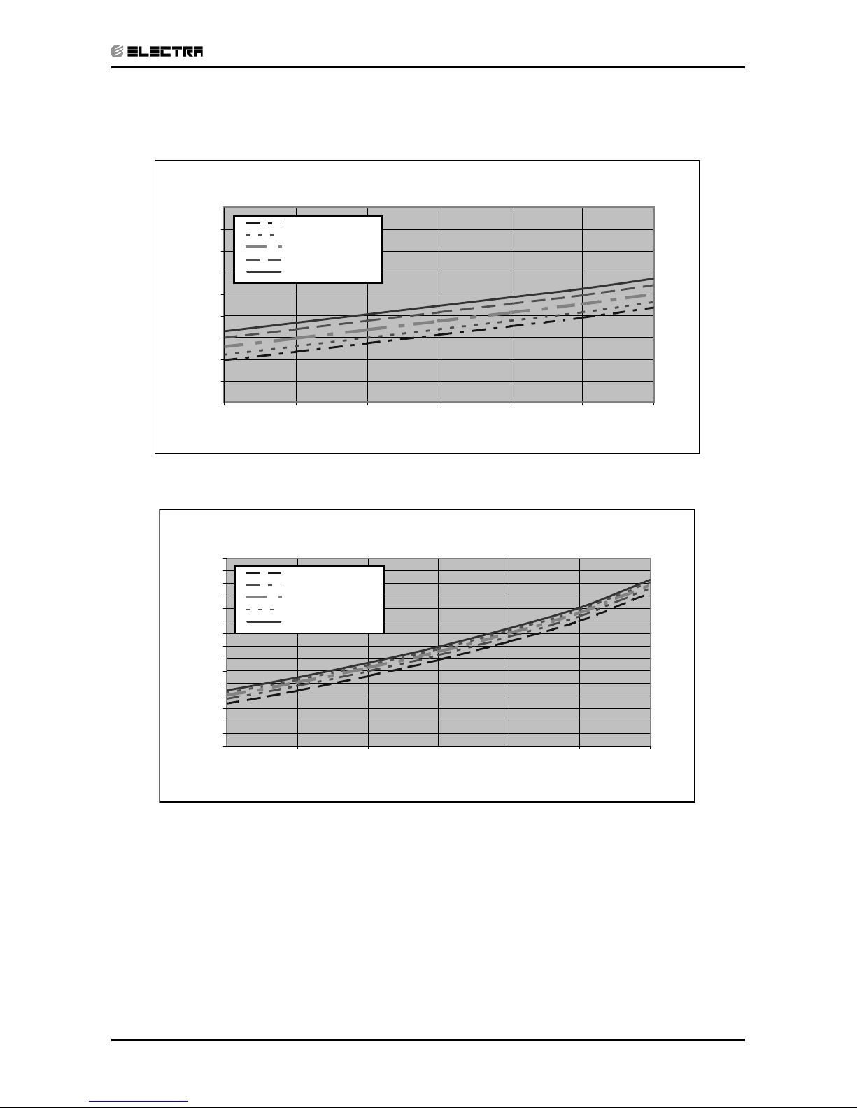
6.3 Outdoor units
6.4 Sound Pressure Level Spectrum
(Measured as Figure 2)
ONG 7 RC Cooling ONG 7 RC Heating
ONG 9 RC Cooling ONG 9 RC Heating
Mic.
Unit
Ground
Figure 2
Page 32

6-3
SOUND LEVEL CHARACTERISTICS
Revision Y06-01Service Manual - LEX
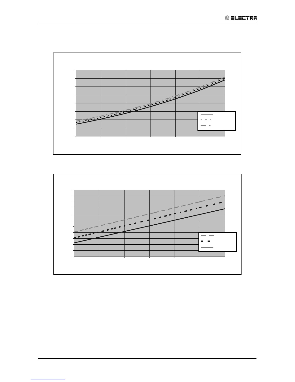
ONG 12 RC Cooling ONG 12 RC Heating
ONG 14 RC Cooling ONG 14 RC Heating
Page 33

7-1
ELECTRICAL DATA
Revision Y06-01Service Manual - LEX
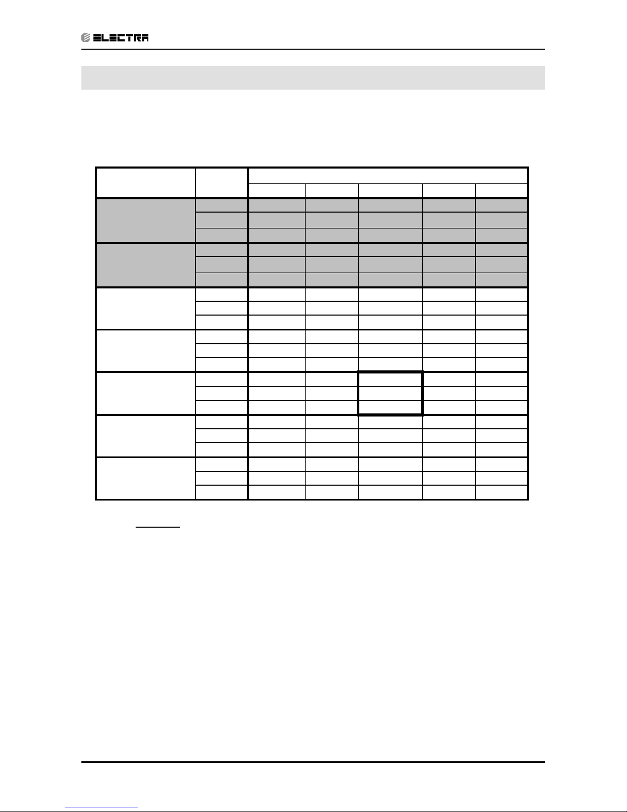
7. ELECTRICAL DATA
7.1 Single Units
MODEL LEX 7 LEX 9
Power Supply
To indoor To outdoor To indoor To outdoor
1PH-230V-50Hz 1PH-230V-50Hz
Max Current, (A) 4.3 6.0
Circuit Breaker,(A) 10.0 10.0
Power Supply Wiring.
(No. x Cross Section mm
2
)
3 x 1.5 mm
2
3 x 1.5 mm
2
Interconnecting Cable RC
Model
(No. x Cross Section mm2)
5 x 1.0 mm2 + 2 x 0.5 mm
2
(OCT sensor)
6 x 1.0 mm2 + 2 x 0.5 mm
2
(OCT sensor)
5 x 1.0 mm2 + 2 x 0.5 mm
2
(OCT sensor)
6 x 1.0 mm2 + 2 x 0.5 mm
2
(OCT sensor)
Interconnecting Cable ST Model
(No. x Cross Section mm2)
4 x 1.0 mm
2
5 x 1.0 mm2 4 x 1.0 mm2 5 x 1.0 mm
2
MODEL LEX 12 LEX 14
Power Supply
To indoor To outdoor To indoor To outdoor
1PH-230V-50Hz 1PH-230V-50Hz
Max Current, (A) 8.2 9.5
Circuit Breaker,(A) 15.0 15.0
Power Supply Wiring.
(No. x Cross Section mm
2
)
3 x 1.5 mm
2
3 x 1.5 mm
2
Interconnecting Cable RC
Model
(No. x Cross Section mm2)
5 x 1.5 mm2 + 2 x 0.5 mm
2
(OCT sensor)
6 x 1.5 mm2 + 2 x 0.5 mm
2
(OCT sensor)
5 x 1.5 mm2 + 2 x 0.5 mm
2
(OCT sensor)
6 x 1.5 mm2 + 2 x 0.5 mm
2
(OCT sensor)
Interconnecting Cable ST Model
(No. x Cross Section mm2)
4 x 1.5 mm
2
5 x 1.5 mm2 4 x 1.5 mm2 5 x 1.5 mm
2
NOTE
Power wiring cord should comply with local lows and electrical
regulations requirements.
Page 34

8-1
WIRING DIAGRAMS
Revision Y06-01Service Manual - LEX
8. WIRING DIAGRAMS
NOTE
Wiring diagram lables as shown on units.
8.1 Indoor Unit: LEX 7,9,12,14 fully feature
8.1.1 Indoor Unit: LEX 7,9,12,14 basic
Page 35

8-2
WIRING DIAGRAMS
Revision Y06-01 Service Manual - LEX
8.2 Outdoor Unit: ONG7 RC R410A
8.3 Outdoor Unit: ONG7ST, 9ST/RC, 12ST/RC, 14ST/RC R410A
Page 36

9-1
ELECTRICAL CONNECTIONS
Revision Y06-01Service Manual - LEX
9. ELECTRICAL CONNECTIONS
9.1 LEX 7, 9, 12, 14 R410A
Page 37

10-1
REFRIGERATION DIAGRAMS
Revision Y06-01Service Manual - LEX
10. REFRIGERATION DIAGRAMS
10.1 Heat Pump Models
10.1.1 LEX 7 R410A
Page 38

10-2
REFRIGERATION DIAGRAMS
Revision Y06-01 Service Manual - LEX
10.1.2 LEX 9, 12, 14 R410A
Page 39

11-1
TUBING CONNECTIONS
Revision Y06-01Service Manual - LEX
11. TUBING CONNECTIONS
TUBE (Inch)
TORQUE (Nm)
¼” ⅜” ½” ⅝” ¾”
Flare Nuts 11-13 40-45 60-65 70-75 80-85
Valve Cap 13-20 13-20 18-25 18-25 40-50
Service Port Cap 11-13 11-13 11-13 11-13 11-13
1. Valve Protection Cap-end
2. Refrigerant Valve Port (use Allen wrench to open/close)
3. Valve Protection Cap
4. Refrigerant Valve
5. Service Port Cap
6. Flare Nut
7. Unit Back Side
8. Copper Tube
When the outdoor unit is installed above the indoor unit an oil trap is required every 5m along the suction
line at the lowest point of the riser. Incase the indoor unit is installed above the outdoor, no trap is
required.
Page 40

12-1
CONTROL SYSTEM
Revision Y06-01Service Manual - LEX
12. CONTROL SYSTEM LEX 7-14 LED BASIC MODEL
12.1 Electronic Control
12.1.1 Introduction
The electronic control information is designed for service applications, and is common
to the following groups of air-conditioners:
• ST/ RC group -Cooling only / cooling and heating by heat pump.
• SH group -Cooling and heating by heat pump and supplementary
heater.
• RH group -Cooling, heating by heaters only.
12.1.2 Jumpers Settings
GROUP J6 Setting J2 Setting
ST / RC Open Open
SH Closed Open
RH Closed Closed
Page 41

12-2
CONTROL SYSTEM
Revision Y06-01 Service Manual - LEX
12.2 Legend
AC - Alternate Current
A/C - Air-Conditioner
ANY - ON or OFF status
CLOCK - ON/OFF Operation Input, (dry contact)
COMP - Compressor
CPU - Central Processing Unit
ELUM - Extended Louver Upward Movement (Software Jumper)
E²PROM, EEP - Erase Enable Programmable Read Only Memory
HE - Heating Element
HPC - High Pressure Control
H/W - Hardware
ICP - Indoor Condensation Pump
ICT - Indoor Coil Temperature (RT2) sensor
IF, IFAN - Indoor Fan
IR - Infra Red
LEVEL1 - Normal Water Level
LEVEL2/3 - Medium/High Water Level
LEVEL4 - Overflow Level
Max - Maximum
Min - Minimum
min - Minute (time)
NA - Not Applicable
OCP - Outdoor Condensation Pump
OCT - Outdoor Coil Temperature (RT3) sensor
OF, OFAN - Outdoor Fan
OPER - Operate
Para. - Paragraph
RAT - Return Air Temperature (RT1) sensor
RC - Reverse Cycle (Heat Pump)
R/C - Remote Control
RCT - Remote Control Temperature
RH - Resistance Heater
RT - Room Temperature (i.e. RCT in IFEEL mode, RAT otherwise)
RV - Reversing Valve
SB, STBY - Stand-By
sec - Second (time)
Sect - Section
SH - Supplementary Heater
SPT - Set Point Temperature
ST - Standard (a Model with Cooling Only)
S/W - Software
TEMP - Temperature
W/O - Without
WVL - Water Valve
ΔT - The difference between SPT and RT.
in Heat Mode: ΔT = SPT-RT
in Cool/Dry/Fan Mode: ΔT = RT-SPT
Page 42

12-3
CONTROL SYSTEM
Revision Y06-01Service Manual - LEX
12.4 General functions
12.4.1 COMP operation
For each Mode including POWER OFF & SB, a Min time delay of 3 min
before COMP restarting, excluding DEICING Mode
The Min operation time of COMP under different operating conditions is
Operation Mode
Min operation time of
COMP
Heat, Cool or Auto Modes 3 min.
Fan, Dry, Overflow, Protection modes, or mode change ignored
12.4.2 IFAN operation
• Min time interval between IFAN speed change in AUTOFAN Mode, is 30 sec.
• Min time interval between IFAN speed change in H/M/L Mode is 1 sec.
• IFAN speed in Heat/Cool Autofan Mode is determined according to the following table:
ΔT IFAN Speed
ΔT ≥ 2 HIGH
2 ≥ ΔT ≥ 1 MED
1 ≥ ΔT LOW
where in Heat Mode: ΔT = SPT-RT
in Cool Mode: ΔT = RT-SPT
Note:
• In Heat Mode, the rules in section 4.0.3 have the higher priority.
• The table above can be represent by a hysteresis curve which
will minimize the switching of the IFAN relay and will minimize the
change in IFAN speed:
T [oc]
L
M
H
IFAN speed
321
12.4.3 OFAN operation
• Min time interval between OFAN ON/OFF state change is 30 sec.
• In general, OFAN starts together with COMP.
12.4.4 HE operation
• Minimum Heaters ON or OFF time is 30 sec.
• Heaters can be activated only if IFAN is on.
Page 43

12-4
CONTROL SYSTEM
Revision Y06-01 Service Manual - LEX
12.4.5 Protections
• High pressure protection is applicable to all operating modes.
• Deicing control is valid in Heat and Auto Heat Mode only.
• Defrosting control is valid in Dry, Cool, Heat and Auto Modes.
• No reset after protection modes.
12.4.6 Thermistors operation
• Return air Temp. is detected by RAT (RT1) in normal Mode, or by RCT (R/C sensor)
in I-FEEL Mode.
• Indoor Coil Temp. is detected by ICT (RT2).
12.4.6.1 Definition of thermistor faults:
a. Thermistor is disconnected The thermistor reading is below -30
o
c.
b. Thermistor is shorted The thermistor reading is over 75
o
c.
c. Thermistor Temp reading doesn’t change (irrelevant for RT1) -
(i) This test is performed only once after a unit is switched from
OFF/STBY to operation. At the first occurrence of 10 min
continuous COMP operation, the current ICT & OCT are
compared with those when the COMP was switched from OFF
to ON 10 min before. If the ΔT is less than 3
o
c, the thermistor is
regarded as defective.
(ii) The ICT and OCT no-change error can be disabled together by
connecting a4.7 kohm resistor (5%) to the OCT connector. These
resistors are equivalent to a thermistor at 43+/-1
o
c and 48+/-1oc
respectively.
(iii) Connecting a 4.7k resistor to the ICT connector will disable the
ICT no-change error only.
Page 44

12-5
CONTROL SYSTEM
Revision Y06-01Service Manual - LEX
12.4.6.2 Cases for disabling thermistor short/disconnected detection
i. The detection of thermistor faults (a) and (b) above, are disabled when Deicer
Protection is started. The detection will be enabled again only after (1) the
deicing is completed, and (2) COMP has been restarted and operated for 30
sec.
ii. When all the following conditions are fulfilled:
a. 4.7K Ohm resistor is connected on the OCT
b. IFAN is OFF
c. Compressor is ON
d. ICT < -30 (disconnected)
This condition come to detect and prevent IFAN operation in Deicer in multi spilt
units.
12.4.6.3 Handling the thermistor faults in a COMP unit
i. ICT/OCT thermistor is disconnected or shorted -
The invalid thermistor temperature is replaced by 43oc, so that the unit
can continue the normal operation. All protections related to that faulty
thermistor will be disabled. For example, in case of any ICT fault, the ICT
high pressure protection in Heat Mode and ICT defrost protection in Cool
Mode will not operate anymore. The same is also applied to the OCT fault.
ii. RAT thermistor is disconnected or shorted –
The RAT will be derived from the ICT by using the equations :
Heat Mode: RAT=ICT/2.3
Cool Mode RAT=ICT*4
Notes:
• In case of any thermistor failure, the STBY LED will be blinking until the
fault condition is corrected.
• User can use the system diagnostics function to find out the nature of
the thermistor faults.
i. RAT thermistor is disconnected or shorted –
System will operate continuously in the last IFAN & WVL status when
turned ON.
Notes:
• As in the COMP unit, the STBY LED will be blinking to indicate a
thermistor fault. And, the user can use the system diagnostics function
to find out the nature of the fault.
Page 45

12-6
CONTROL SYSTEM
Revision Y06-01 Service Manual - LEX
12.5 Cooling Mode - General
1) Room Temperature, RT, is detected by
• RAT in normal operation, or
• RCT (R/C sensor) in I-FEEL mode.
2) The resolution of RT is 1oc.
• RT is activating COMP/WVL if (RT > SPT), and
• RT is stopping COMP/WVL if (RT =< SPT).
3) Indoor Coil Temp is detected by ICT (RT2).
4) Outdoor Coil Temp is detected by OCT (RT3).
5) A WVL-RC/SH will work in Cooling Mode when
• ICT < 16
o
c in general (see Sect 2.2.2 for details), and
• Unit is not operating in Fan Mode.
6) OFAN OPERATIONS
• OFAN starts together with COMP in general.
Page 46

12-7
CONTROL SYSTEM
Revision Y06-01Service Manual - LEX
12.5.1 Cooling
Mode: Cool, Auto (at Cooling)
Temp: Selected desired temperature.
Fan: HIGH, MED, LOW
Timer: Any
I Feel: On or Off
Control function
Maintains room temp at desired level by comparing RT and SPT.
(RT - SPT) [oc]
+3
+2
+1
0
-1
-2
ON
OFF
ON
OFF
USER FAN SPEED
ON
OFF
COMP
(WVL)
OFAN
IFAN
RV
Note:
1) IFAN is always running at High, Medium or Low speed selected by user.
2) In IFEEL mode, the Room Temperature (RT) is the RCT from a R/C. Otherwise, the
RT is the RAT from the Room Thermistor.
Page 47

12-8
CONTROL SYSTEM
Revision Y06-01 Service Manual - LEX
12.5.2 Cooling with Autofan
Mode: Cool, Auto (at cooling)
Temp: Selected desired temperature
Fan: Auto
Timer: Any
I Feel: On or Off
Control function
Maintains room temp at desired level and controls the IFAN speed for optimal comfort.
(RT - SPT) [oc]
+3
+2
+1
0
-1
-2
ON
OFF
ON
OFF
H
L
M
ON
OFF
COMP
(WVL)
OFAN
IFAN
RV
Page 48

12-9
CONTROL SYSTEM
Revision Y06-01Service Manual - LEX
12.6 Heating Mode
12.6.1 Heating Mode - General
• In heating Mode, temp. compensation schedule will be activated for wall mounted
units.
SPT [oc]
Add to SPT
I-FEEL ON I-FEEL OFF
18 ≤ SPT ≤ 27 0
o
c +2 oc
27 < SPT ≤ 30 0
o
c+3
o
c
Notes :
• No compensation will be activated in Forced operation modes
12.6.2 IF operating rules
• As a general rule for RC and SH groups, when COMP is ON, excluding
protection modes, IFAN will be switched ON if
• ICT > 35oc or
at the IFTC 30 sec after the COMP is switched ON. In
this case, the IFAN will be started at low speed.
Notes :
1) In SH or RC group, if HE is set to OFF due to low ICT, IFAN will be
switched to LOW and will be turned OFF after 30 sec.
2) An exception to this rule (4.0.3.a) is the Back-up mode for SH.
• In RC and SH groups, whenever COMP & HE are both
OFF, excluding protection modes, IFAN operation will be according
to the following:
In other models IFAN will operate in low speed for 30 sec and then stop. If
COMP is OFF for more than 3 minutes and IFEEL Mode is inactive, IFAN will
operate in low speed according to the following graph:
IFAN Speed
Any
Low
Stop
30 35 40
EMD/ELD
EMD/ELD
ICT [oc]
15 20 25
General :
For WAX :
SPT+4 SPT+6 ICT
[
o
c
]
ON
OFF
IFAN (Low Speed)
Page 49

12-10
CONTROL SYSTEM
Revision Y06-01 Service Manual - LEX
12.6.3 HE operation
• For all Groups, HE can be ON only when IFAN is ON.
• For all Groups, HE switches to OFF when ICT > 50
o
c, and is activated
again when ICT ≤ 45oc.
• In SH or RC group, HE operation is limited by the following graph:
• Back-up mode for SH group
After COMP has been working for 5 minutes, HE & IFAN are activated even
if the ICT is still below 35
o
c. This situation is called Back-up Mode. Both
HE & IFAN will work in Back-up Mode until the ICT reaches 35oc. Then, the
operation goes on in the usual mode .
HE
ON
OFF
30
45 50
ICT [oc]
15
General :
For WAX :
35
20
40
Page 50

12-11
CONTROL SYSTEM
Revision Y06-01Service Manual - LEX
12.6.4 Heating, RC or SH Group
Mode: Heat, Auto (at heating)
Temp: Selected desired temperature
Fan: HIGH, MED, LOW
Timer: Any
I Feel: On or Off
Control function
Maintains room temp. at desired level by comparing RAT or RCT to SPT.
(RT - SPT) [oc]
+2
+1
0
-1
-2
-3
ON
OFF
ON
OFF
H/M/L
OFF
L
ON
OFF
Note 1 Note 2
COMP
(WVL)
HE1
HE2
IFAN
ON
OFF
RV
Page 51

12-12
CONTROL SYSTEM
Revision Y06-01 Service Manual - LEX
12.6.5 Heating, RC or SH Group with Autofan
Mode: Heat, Auto (at heating)
Temp: Selected desired temperature
Fan: Auto
Timer: Any
I Feel: On or Off
Control function
Maintains room temp at desired level by controlling COMP, IFAN and OFAN.
(RT - SPT) [oc]
+2
+1
0
-1
-2
-3
ON
OFF
ON
OFF
H
OFF
L
M
ON
OFF
Note 1 Note 2
COMP
(WVL)
HE1
HE2
IFAN
RV
ON
OFF
Page 52

12-13
CONTROL SYSTEM
Revision Y06-01Service Manual - LEX
12.6.6 OFAN operation is controlled by the graph below when
1. (RAT ≥ SPT – 2oc), AND
2. (ICT ≥ 45
o
c), AND
3. (COMP is ON)
Otherwise, OFAN runs together with COMP.
OCT [oc]
+3
+2
+1
0
-1
OFAN
ON
OFF
Page 53

12-14
CONTROL SYSTEM
Revision Y06-01 Service Manual - LEX
12.7 Automatic Cooling or Heating
12.7.1 Automatic Cooling or Heating - General
• Switching-temperature between Cooling and Heating is SPT ± 3oc.
• Autofan in Automatic Cooling and Heating Mode will activate “Cooling
with Autofan Mode” and “Heating with Autofan Mode” respectively.
• When the Auto Mode is started with SPT +/-0
o
c, the unit will not select
Auto Heat or Auto Cool mode immediately. Instead, the unit will be in
a temporary Fan Mode with IFAN operating at low speed.
The proper Auto Heat mode or Auto Cool will be started whenever the RT
reaches SPT-1oc or SPT+1oc respectively.
• For RC & SH units, Mode change between Auto Heat & Auto Cool
Modes is possible only after the COMP has been OFF during the
last T minutes.
Mode Change time, T
Auto Cool to Auto Heat 3 min
Auto Heat to Auto Cool 4 min
• When unit is changed form Cool/Dry mode to Auto Mode, the unit
will continue to operate at (Auto) Cool Mode until the conditions for
switching from Auto Cool to Auto Heat are satisfied.
Similarly, when unit is changed from Heat Mode to Auto Mode, the
unit will continue to operate at (Auto) Heat Mode until the conditions
for switching from Auto Heat to Auto Cool are satisfied.
Page 54

12-15
CONTROL SYSTEM
Revision Y06-01Service Manual - LEX
12.7.2 Auto Cooling or Heating, RC or SH Groups
Mode: Auto
Temp: Selected desired temperature
Fan: Any
Timer: Any
I Feel: On or Off
Control function
Maintains room temp at desired level by selecting between cooling and heating modes.
(RT - SPT) [oc]
+3
+2
+1
0
-1
-2
-3
ON
OFF
ON
OFF
H/M/L/OFF
L/OFF
ON
OFF
ON
OFF
COMP
& OFAN
HE1
HE2
IFAN
RV
H/M/L/OFF
L/OFF
USER FAN SPEED H/M/L/OFF
L/OFF
Auto Cool Mode Auto Heat Mode
> 4 min > 3 min
> 3 min > 2 min
(3) (3)
(4)
(4)
(5)
Auto Heat Mode
Page 55

12-16
CONTROL SYSTEM
Revision Y06-01 Service Manual - LEX
12.8 Dry Mode
12.8.1 Dry, ST or RC group
Mode: Dry
Temp: Selected desired temp
Fan: Low (automatically selected by software)
Timer: Any
I FEEL: Any
Control function
Reduce room humidity with minimum temp. fluctuations by operating in Cool Mode with
low speed IFAN.
Notes :
• When Dry is ON, the COMP is forced OFF for 3.5 min (longer than the
3 min Min COMP-Off time) after every 15 min of continuous COMP
operation.
• When Dry is OFF, the COMP is forced ON for 6 min (longer than the 3
min Min COMP-On time) after every 15 min of continuous COMP OFF
time.
• When Dry is changed from ON to OFF or vice versa, the limits
mentioned in (1) & (2) are ignored. The COMP operation is only
controlled by the 3 min Min OFF time and 1 min Min ON time.
• In Dry Mode, IFAN is LOW when COMP is ON, and is OFF when
COMP is OFF.
DRY
(RT - SPT) [oc]
+2
+1
0
-1
-2
ON
OFF
ON
OFF
LOW
OFF
DRY-ON
DRY-OFF
ON
OFF
Time [min]
10
20
30
40 50
Max 15 minutes
3.5
min
Note1
6 min
Note 2
COMP
& OFAN
HE1
& HE2
IFAN
RV
Max 15 minutes
5 minutes COMP
ON time
Page 56

12-17
CONTROL SYSTEM
Revision Y06-01Service Manual - LEX
12.9 Protection
12.9.1 Cooling Mode Protections
Indoor Coil Defrost
Mode: Cooling, Dry, Auto
Temp: Selected desired temp.
Fan: Any
Timer: Any
I Feel: On or Off
Control Function
Protect the indoor coil from ice formation at low ambient temperature.
t1 = 5 min minimum for each COMP starting
t2 = OFAN cycling (alternate between ON and OFF every 30 sec) for 20 min
maximum
t3 = COMP and OFAN stop for 10 min minimum
Notes:
• When J7 is closed (connected), OFAN cycling is cancelled and the
set temperature for COMP & OFAN cut-out and cut-in are changed.
COMP & OFAN are forced OFF when ICT =< -6
o
c, and are kept OFF
until ICT > 14
o
c.
• For WAX model, the defrost processes is simpler. When J7 is open,
COMP & OFAN are forced OFF when ICT =< -1
o
c, and are kept OFF
until ICT > 5oc. When J7 is closed, the WAX defrosting process is the
same as that of the other models (R.H.S. of the graph above). In both
cases, the ICT checking in t2 and t3 are not applied.
ICT [oc]
+2
ON
OFF
ON
OFF
t1 t2 t3
COMP
OFAN
+1
+5
+14
0
-1
-6
ON
OFF
IFAN
J7 OPEN J7 CLOSED
t1 t1
Page 57

12-18
CONTROL SYSTEM
Revision Y06-01 Service Manual - LEX
12.3.2 High Pressure Protection
Mode: (Auto) Cooling or Dry
Temp: Selected desired temp.
Fan: Any
Timer: Any
I Feel: On or Off
Control Function
To protect the COMP from the high pressure built-up in the outdoor coil during normal
cooling operation, by switching OFF the IFAN and COMP.
OCT [oc]
Any
OFF
Any
ON
Any
Blink
ON
COMP
OFAN
IFAN
OPER
LED
52
55
61
66
L
COMP is forced OFF
OFAN is forced ON
IFAN forced
to LOW
68
OFAN follow operation of
COMP
COMP is forced OFF
OFAN is forced ON
For all models except WAX & P2000 For WAX & P2000 models
Note:
• The ICT is also monitored during Cool and Dry mode, in case the RV control circuit
is faulty. Whenever ICT reaches 70oc, which indicates a high pressure in the indoor
coil, the COMP will be forced off automatically. The COMP can be turned on again only
after the ICT is under 70oc again and after the 3 min COMP ON delay time. The OPER
LED will not blink in this case.
Page 58

12-19
CONTROL SYSTEM
Revision Y06-01Service Manual - LEX
12.9.3 Heating Mode Protections
Outdoor coil Deicing (excluding RH Group)
Mode: Heating, Auto (at heating)
Temp: Selected desired Temp
Fan: Any
Timer: Any
I FEEL: Any
Control function
Protects the Outdoor coil from ice formation by controlling COMP & RV operation.
Scope
This new deicer is designed to operate at extreme temp conditions. The deicing cycle
could be triggered from:
1. OCT temp and time between two consecutive deicing cycles.
2. Detection of ice forming by change of the OCT temp.
Both algorithms adjust the time between deicing cycles to optimize the A/C
performance. The algorithm will automatically increase the time between deicing cycles
and reduce the deicing cycle as needed.
The algorithm uses EEPROM data to operate.
Page 59

12-20
CONTROL SYSTEM
Revision Y06-01 Service Manual - LEX
Deicing procedure
OCT [oc]
ON
OFF
ON
OFF
ON
L
ANY
COMP
OFAN
RV
IFAN
DST
(DDT)
0
12
OFF
HEs are forced ON
DOC
ANY
ON
HE
36s 36s
DT
30s
max 12 min.
Note 3
DI (note 1)
DI (note 2)
30s
3 min 3 min
IFAN
OFF
ANY
HE
OFF
ANY
all SH units
except WAX
RC or WAX units
HEs are forced OFF
IFAN is forced to Low Speed
BLINK
ON
OPER
LED
Notes :
• At the first COMP activation after SB or OFF, if (OCT < 0oc), then DI = 10
min, else DI = 40 min.
• In the following Deicing cycles, the time interval between two Deicing
cycles activation is between 30 to 80 min (refer to the flow chart).
• For RC group, HEs are forced OFF. IFAN operation is as in Heat
Mode, Sect 4.0.3.a, i.e. IFAN will be set to OFF when ICT<30
o
c.
For WAX, the IFAN is simply forced OFF.
• For SH group, HEs are forced ON and IFAN is forced to operate in Low
speed, regardless of the ICT and difference between RAT & SPT.
Page 60

12-21
CONTROL SYSTEM
Revision Y06-01Service Manual - LEX
12.9.4 High pressure protection (excluding RH Group)
Mode: (Auto) Heating
Fan: Any
Timer: Any
I Feel: On or Off
Control Function
Protect the Compressor from high pressure by switching OFF the OFAN and COMP.
ICT [oc]
Any
Off
Any
Off
COMP
OFAN
52
55
61
66
COMP is forced OFF
67
OFAN is force
Off
COMP is forced OFF
For all models except WAX For WAX model
ON
BLINK
OPER
LED
Notes:
• IFAN, HE1 and HE2 will be activated according to the relevant
Heating Mode Sect.
• In case of any malfunction in the relay control circuit, the OCT is also
monitored during heating mode. Whenever OCT reaches 70
o
c, which indicates
a high pressure in the outdoor coil, the COMP will be forced off automatically.
The COMP can be turned on again only after the 3 min COMP ON delay and the
OCT is under 70oc. The OPER LED will not blink in this case.
Page 61

12-22
CONTROL SYSTEM
Revision Y06-01 Service Manual - LEX
12.10 Timer
Mode: Any
Temp. Selected desired temp
Fan: Any
Timer: Timer On, Timer Off
I Feel: On or Off
Control function
• Starts or stops the unit operation after pre-set time. If RC-1 is used,
the timer setting will be (0.5 - 24 Hr) from the moment the timer is set.
The minimum resolution is 30 minutes.
If RC-2 or later version of remote controls is used, the timer
setting will be (0:00 - 23:50) real time with 10 minutes resolution.
• After power failure, all pre-set timers are cleared. The system is
forced to STBY mode and the Timer LED indicator is blinked to
indicate the situation. The LED keeps blinking until the timer settings
can be reloaded from a R/C message.
Note: If all timers are inactive, the system will not be forced
OFF after the power failure. The last OPER/STBY status will
be loaded from the EEP instead.
• When the A/C receives any valid message from a R/C, the current
ON/OFF timer settings will be replaced by the new timer settings in
the R/C message.
Note: The following timer related operations will not affect the
A/C operating mode (Heat/Cool/Auto/Dry/Fan) setting.
• Set ON/OFF timer
• Clear ON/OFF timer
• R/C ON Timer is time-up
• R/C OFF Timer is time-up
E.g. When a STBY A/C unit (with Cool Mode setting in its EEP) is
turned on by the ON-TIMER of a R/C with heat mode setting,
the A/C will start in Cool Mode.
Page 62

12-23
CONTROL SYSTEM
Revision Y06-01Service Manual - LEX
12.11 Forced Operation
Forced operation allows units to start, stop and operate in Cooling or Heating in pre-set
temperature according to the following table:
Forced operation
mode
Pre-set Temp for :
WMF, WMN, WNG models
Cooling 22°C
Heating 28°C
Note:
• While under the forced operation, the temperature compensation
schedule.
• The forced operation is activated when the mode button on the
Display Board is used to switch the unit to Cool or Heat mode.
• The IFAN is always set to Autofan Speed in forced operation.
Page 63

12-24
CONTROL SYSTEM
Revision Y06-01 Service Manual - LEX
12.12 Sleep Mode
Mode: Any
Temp: Set – desired temperature selected
Fan: Any
Timer: Interact with Sleep Timer as described in sect 12.2
I Feel: On or Off
The Sleep mode is activated by using the sleep button on the R/C. In Sleep Mode,
the unit will automatically adjust the SPT to turn up/down the room temperature (RT)
gradually to provide maximum comfort to the user in sleep.
Sleep is treated as TIMER function. Therefore, the TIMER LED is activated similar to
TIMER function.
12.12.1 Adjustment in Sleep Mode
1. in cool, auto cool or dry modes, the SPT adjustment is positive (from 0 to +3oc).
2. In heat or auto heat modes, the SPT adjustment is negative (from 0 to -3
o
c).
3. In other modes, there is no SPT adjustment.
4. The SPT adjustment is cancelled when the Sleep mode is cancelled.
Note: If Off-timer is active, the unit may go to SB before or after 7 hours of
sleep operation.
SPT
Time [Hr]
485326
Start
Sleep
7
RT
SPT-1
SPT-2
SPT-3
SPT+2
SPT+1
SPT+3
1
7 Hours Sleep operation
for Normal Sleep Mode
Unit is turned to SB
after Sleep
Cool, Dry modes
Heat mode
Page 64

12-25
CONTROL SYSTEM
Revision Y06-01Service Manual - LEX
12.12.2 Time adjustment in Sleep Mode
The user can make use of the Off-Timer to extend the Sleep Time from 7 hours to 12
hour (max). The operation of the new “Extended Sleep Mode” is illustrated by the
graphs below.
Case 1 is the Standard Sleep Mode, which is the only sleep mode in previous version
of MCU. The A/C unit simply works for 7 hours, then goes to SB.
Case 2 is the new Extended Sleep Mode. If an active Off-Timer is set to turn off the
A/C between 7-12 hour, relative to the starting of Sleep, the Sleep time is extended.
And, instead of going to SB at the 7th hour, the A/C will work until reaching the Off-time.
Case 3 is an exception to case 2. The Sleep Mode will not be extended to the Off-Time
when the Off-Timer is preceded by an On-Timer, which is also between 7-12 hour.
Oper
Time [Hr]
48101226
Start
Sleep
7
Case 1 : Standard Sleep Mode
Condition : Off-timer is not set or is beyond 12 hour.
SB
Oper
Time [Hr]
48101226
Start
Sleep
7
Case 2 : Extended Sleep Mode
Condition : Off-timer is set at 7-12 hour.
SB
Off-timer
Oper
Time [Hr]
48101226
Start
Sleep
7
Case 3 : Exception to Case 2
Condition : Off-timer is set at 7-12 hour
On-timer is set at 7-12 hour and before Off-timer
SB
Off-timerOn-timer
Page 65

12-26
CONTROL SYSTEM
Revision Y06-01 Service Manual - LEX
12.13 Clogged Air Filter
Filter LED ON after 512 HR.
Filter LED is turned OFF, and the Filter Timer is restarted by pressing the reset button.
Page 66

12-27
CONTROL SYSTEM
Revision Y06-01Service Manual - LEX
12.14 Controller Self-Test Procedure
12.14.1 By Shorting Test Jumper J1
RC/ST TEST
MODEL
CONFIGURATION
TEST
STEP MOTOR TEST
FREQUENCY
TEST
LEDS OFF
LEDS ON TEST
AUTO RELAY
TEST
SHORT JUMPER
J1
(CONTROL PCB)
PRESS ON
POWER
BUTTON
PRESS ON
MODE BUTTON
INDOOR FAN
SPEED TEST
SELF-TEST FLOW CHART
Step 1
Step 2
Step 3
FOR CONTROLLER (VERSION 4V5 OR HIGHER)
COOL
HEAT
COMPRESSOR
OUTDOOR FAN
R.V.
LOW
MEDIUM
HIGH
TIMER
OPERATE
STANDBY
BUZZER TEST
(ONE BEEP SOUND)
REMOTE CONTROL
TO CPU COMUNICATION
(TWO BEEPS SOUNDS)
THERMISTOR ANALOG
VOLTAGE CHECKING
EEPROM MEMORY
TEST
END OF SELF
TEST
PRESS ON RESET
BUTTON
PRESS ON FAN
BUTTON ON THE
REMOTE CONTROL
PRESS ON MODE
BUTTON
PRESS ON MODE
BUTTON
Step 4
Step 5
Step 6
Step 7
Step 8
DISCONNECT
JUMPER
J1
Page 67

12-28
CONTROL SYSTEM
Revision Y06-01 Service Manual - LEX
12.14.2 By Remote Control Settings:
a. 1: TURNING ON THE POWER.
Turn ON the power, make sure that the unit is in operation.
b. STEP 2 : ENABLE SELF-TEST MODE
• Use the remote control to send the first settings to display / indoor unit
HEAT mode, HIGH IFAN, set temperature to 16 ºC, no I-FEEL Sleep or
any other timer settings are needed.
• Cover the IR transmitter components in the remote control so that it will
not transmit the signals to the indoor unit display.
• Use the remote control to send the second settings to display / indoor unit
COOL mode, LOW IFAN, no I-FEEL Sleep or any other timer settings.
• Uncover the remote control IR transmitter and change the temperature
settings. If the display/indoor unit receive the settings properly the
following steps will start:
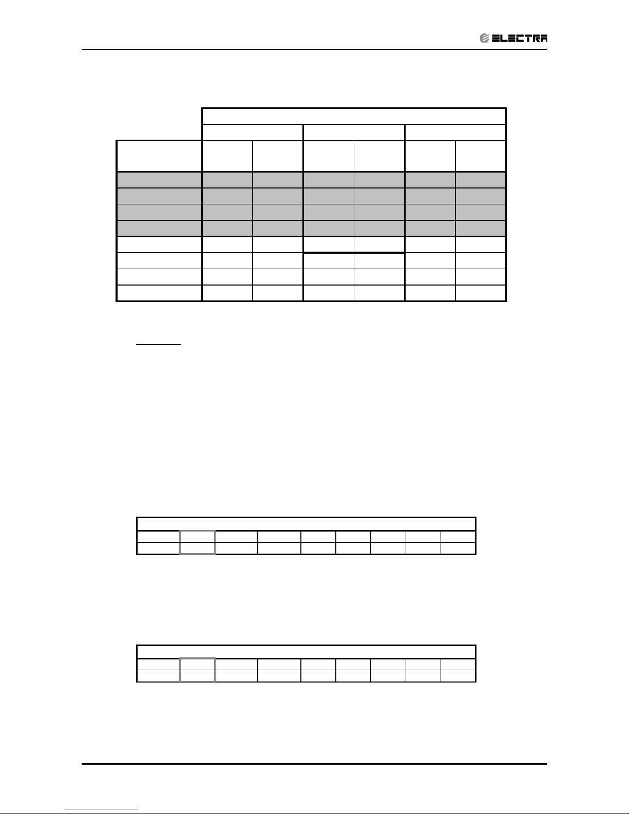
c. STEP 3: MODEL SETTING CONFIRMATION
• The STAND-BY and COOL LEDS will indicate the operation mode as
follows:
OPERATION MODE STAND-BY LED COOL LED
ST ON OFF
RC OFF OFF
SH OFF ON
RH ON ON
• Testing the Model configuration. Selected by the COMP, STAND-BY,
TIMER LEDS and FILTER will indicate the model configuration as follows
(the relevant line for this manual is highlighted):
MODEL COMP OPERATE LED TIMER LED FILTER LED
WNG ON OFF OFF OFF
WMN1 ON ON OFF ON
WMN4 OFF OFF ON OFF
WMN2/WHX OFF ON OFF ON
WMN3 OFF ON ON ON
In this term the step motor will turn to HOME POSITION.
Page 68

12-29
CONTROL SYSTEM
Revision Y06-01Service Manual - LEX
d. STEP 4 : AUTO LED WALK TEST.
• All the LEDS will turn OFF.
• All the LEDS will turn ON for 1 second one by one in the following
sequence:
STAND-BY OPERATE TIMER FILTER COOL HEAT.
• In PRX all the LEDS will turn ON for 1 second one by one in the following
sequence : 18 °c 20 °c 22 °c 24 °c 26 °c 28 °c 30 °c
High IFAN Auto IFAN Med IFAN Low IFAN STAND-BY
TIMER FILTER COOL HEAT.
e. STEP 5: AUTO REALY WALK TEST:
• All relays will energize one by one in the following sequence:
COMPRESSOR OUTDOOR FANR. V. HEATER 1 HEATER 2
INDOOR WATER PUMP SWING or OUTDOOR WATER PUMP
INDOOR FAN: LOW MID HIGH.
• When the relay walk test is completed, the next test will start
automatically.
f. STEP 6: FREQUENCY TESTING:
• If the frequency measuring process fails the COOL LED will turn ON.
In order to move to the next step, press ON/OFF button on the remote
control.
g. STEP 7: INPUT TEST.
• The test purpose is to check the analog real time indicators (thermistors,
LEVEL and clock) according to the table below.
LED Indicator Condition for LED to be ON
STBY LED Room thermistor ≠ 25°c
OPER LED Indoor coil thermistor ≠ 25°c
TIMER LED Outdoor coil thermistor ≠ 25°c
FILTER LED Clock
COOL LED LEVEL 2&3
HEAT LED LEVEL 4
h. STEP 8: TIMING RESET TEST (WATCH DOG).
• The test purpose is to verify that the CPU rise time after power failure
is between 1 to 3 sec, test results are indicated on the LEDS : STANDBY,OPER, TIMER and FILTER turning ON one by one.
• The results of the test are coded as follows:
Pass condition:
1 sec - STAND-BY and OPER are turned ON
2 sec - STAND-BY, OPER and TIMER are turned ON
Page 69

12-30
CONTROL SYSTEM
Revision Y06-01 Service Manual - LEX
Fail condition:
0 sec - STAND-BY is turned ON
3 sec - STAND-BY, OPER, TIMER and FILTER are turned ON
• When the timing reset test is completed, the next test will start
automatically.
i. STEP 9: MEMORY TEST (EEPROM)
• The test purpose is to check if the memory is functioning correctly. The test
result is reported by using the STAND-BY and FILTER LEDS:
LED Indicator Condition for LED to be ON
STAND-BY LED Test passed
FILTER LED Test failed
AT THIS POINT THE SELF-TEST IS COMPLETED.
In order to terminate Self-Test mode the User can change the unit setting from COOL
Mode, LOW FAN to COOL Mode, MED FAN or to wait without using the remote control
for 60 sec.
Values of Sensors Temperature VS. Voltage (DC)
Temp. (*C) Voltage (V) Temp. (*C) Voltage (V) Temp. (*C) Voltage (V) Temp. (*C) Voltage (V)
-20 4.554 2 3.744 24 2.555 46 1.487
-19 4.529 3 3.695 25 2.5 47 1.447
-18 4.502 4 3.646 26 2.445 48 1.409
-17 4.475 5 3.595 27 2.391 49 1.371
-16 4.446 6 3.544 28 2.338 50 1.334
-15 4.417 7 3.492 29 2.284 51 1.298
-14 4.386 8 3.439 30 2.232 52 1.263
-13 4.354 9 3.386 31 2.18 53 1.228
-12 4.322 10 3.332 32 2.128 54 1.195
-11 4.287 11 3.278 33 2.077 55 1.162
-10 4.252 12 3.223 34 2.027 56 1.13
9 4.216 13 3.168 35 1.978 57 1.099
-8 4.178 14 3.113 36 1.929 58 1.069
-7 4.14 15 3.058 37 1.881 59 1.04
-6 4.1 16 3.002 38 1.834 60 1.011
-5 4.059 17 2.946 39 1.798 61 0.983
-4 4.017 18 2.89 40 1.742 62 0.956
-3 3.974 19 2.833 41 1.698 63 0.929
-2 3.93 20 2.777 42 1.654 64 0.904
-1 3.885 21 2.722 43 1.611 65 0.879
0 3.839 22 2.666 44 1.569 66 0.854
1 3.792 23 2.61 45 1.527 67 0.831
Page 70

12-31
CONTROL SYSTEM
Revision Y06-01Service Manual - LEX
12.15 On Unit Indicators and Controls
STAND BY
INDICATOR
Lights up when the Air Conditioner is connected to power and
ready to receive the R/C commands
Blinks continuously in case of any thermistor failure.
OPERATION
INDICATOR
Lights up during operation.
Blinks for 300 ms, to announce that a R/C infrared signal has
been received and stored.
Blinks continuously during
• OCT High Pressure Protection Mode
• ICT High Pressure Protection Mode
• Deicing in Heating Mode
• Water Over Flow in ECC Model
TIMER INDICATOR Lights up during Timer and Sleep operation.
FILTER INDICATOR
Lights up when Air Filter needs to be cleaned.
Blinks during Water Over Flow in MBX/P2000 models.
COOLING
INDICATOR
Lights up when system is switched to Cool Mode by using the
Mode Switch on the unit.
Show the thermistor status in Diagnostic Mode
HEATING
INDICATOR
Lights up when system is switched Heat Mode by using the
Mode Switch on the unit.
Show the thermistor status in Diagnostic Mode.
MODE BUTTON
(Cool, Heat, SB)
Use to cycle the operation mode of the A/C unit among COOL,
HEAT and SB modes, without using the R/C.
Every time this switch is pressed, the next operation mode is
selected, in this order :
SB Cool Mode Heat Mode SB ...
Press this button continuously for 5 sec or more to start the
Diagnostic Mode.
RESET / FILTER
BUTTON
When the Filter LED is ON, press to turn off the Filter LED
after a clean filter has been reinstalled.
When the Filter LED is OFF, use this button to enable/disable
the buzzer announcer.
Page 71

12-32
CONTROL SYSTEM
Revision Y06-01 Service Manual - LEX
12.16 Clock Random Delay From 0 to 2.5 seconds
0 = Clock Switch Open
1 = Clock Switch close
The Clock is activate according to the following table:
A/C STATE
(before clock is changed)
CLOCK STATE
(before clock is changed)
CLOCK ACTION
(clock is changed)
A/C NEW STATE
(after clock is changed)
ON 1 0 OFF
OFF 0 1 ON
OFF by
interrupt
(1)
1 0 OFF
ON by
interrupt
(1)
01ON
Notes :
1. Clock can be interrupted by :
• R/C - POWER ON/OFF Push-button.
• R/C - TIMER.
• R/C - SLEEP.
• A/C - MODE SWITCH.
2. Any change in the CLOCK level during the first 6 sec after the system
Reset is ignored.
Page 72

12-33
CONTROL SYSTEM
Revision Y06-01Service Manual - LEX
12.17 System Diagnostics
Pressing Mode button for 5-10 seconds in SB or any other operation mode will
activate diagnostic mode by the acknowledgment of 3 short beeps and lighting of
COOL and HEAT LEDs.
In diagnostic mode, system problems will be indicated by blinking of Heat & Cool
LEDs.
The coding method will be as follow:
Heat led will blink 5 times in 5 seconds, and then will be shut off for the next 5
seconds. Cool led will blink during the same 5 seconds according to the
following table:
No Problem
żżżżż
1 RT1 is disconnected żƔƔƔƔ
2 RT1 is shorted żƔƔƔż
3 (Reserved) żƔƔżƔ
4 RT2 is disconnected ƔżƔƔƔ
5 RT2 is shorted ƔżƔƔż
6 (Reserved) ƔżƔżƔ
7 RT2 temp reading doesn’t change ƔżƔżż
8 RT3 is disconnected ƔƔżƔƔ
9 RT3 is shorted ƔƔżƔż
10 (Reserved) ƔƔżżƔ
11 RT3 temp reading doesn’t change ƔƔżżż
12 RT2 & RT3 temp reading doesn’t change Ɣżżżż
ż - ON, Ɣ - OFF
Notes:
1. If faults occur in more than one thermistor (except case number 12 on the table
above), only one fault will be indicated according to the following order: RT3,
RT2, RT1.
2. A/C will jump out to normal mode if sending a command by the R/C in the
system diagnostics mode. If this command from the R/C contain a Group ID, this
ID will become the new Group ID of the ELCON unit.
Page 73

12-34
CONTROL SYSTEM
Revision Y06-01 Service Manual - LEX
12B. CONTROL SYSTEM LEX 7-14 LED FULLY FEATURED
12B.1 General Functions
12B.1.1 Operation Modes
x Auto Mode
x Cooling Mode
x Drying Mode
x Fan Mode
x Heating Mode
12B.1.2 Functions
x I FEEL,
x Forced Mode,
x Protection - hot keep, Deicing, defrosting,
x Timer,
x Sleep,
x Fresh Air,
x Ionizer,
x E.S.F,
RCT: remote controller temperature
SPT: set point temperature
Page 74

12-35
CONTROL SYSTEM
Revision Y06-01Service Manual - LEX
12B.2 Operation Modes
12B.2.1 Auto Mode Operation
Heating / Fan Drying Cooling
22ºC 26ºC RT
x If RT >= 26ºC - A/C will go into Cooling Mode; Initial SPT is 25ºC.
x If 22ºC < RT < 26ºC- A/C go into Drying mode; Initial SPT is 24ºC.
x If RT <= 22ºC - A/C will go into Heating Mode; Initial SPT is 23ºC.
x For Cooling only, If RT <= 22ºC - A/C will go into Fan Mode; Initial SPT is
23ºC.
x IFAN speed range: Auto, Low, Mid and Hi. Initial speed: Auto.
x SPT can be set by R/C command (heating, cooling, dry or fan mode).
x The Mode can not be changed.
x If RT is invalid, it will go into Drying mode state (2).
12B.2.2 Cooling Mode
x SPT range: 16ºC-30ºC. Initial: 24ºC;
x IFAN speed range: Auto, Low, Mid and High. Initial speed: Hi;
x Auto Fan
IFAN H
M
L
SPT+1ºC SPT+2ºC SPT+3ºC SPT+4ºC RT
Note:
1. When fan speed changes from Low speed to High speed, there is 3 minutes
delay to avoid the fan speed changing frequently. But not vice versa.
2. If RT is invalid and the fan speed is set to Auto, IFAN will operate at medium
speed.
Page 75

12-36
CONTROL SYSTEM
Revision Y06-01 Service Manual - LEX
12B.2.3 Comp’ Operation
COMP On
Off
SPT-1ºC SPT+1ºC RT
x If RT >= SPT+1ºC, COMP and OFAN is activated;
x If RT <= SPT-1ºC, COMP stop, OFAN will turn off after 5 seconds delay.
Note:
x COMP turns off have 3 min delay protection;
x COMP turn on have 5 min continues protection.
x OFAN will turn off 5 seconds after COMP stop, when turning the unit off or
changing to heat mode.
x RV & AHEAT closes.
x Louvers action rules see 3.7
x Sleep Function, see 3.1
12B.2.4 Defrosting
ICT (ºC)
+7
+1
0
-3
>= 5 min 1 min >= 5 min
COMP ON
OFF
OFAN ON
OFF
x IFAN always run at the set speed.
x After COMP is on for 5 minutes, if (ICT <= -3ºC) during 1 minute, COMP and
OFAN stop. If (ICT > 7ºC), COMP and OFAN will resume to the normal
operation.
Note: If ICT is invalid, defrosting protection cannot be activated
Page 76

12-37
CONTROL SYSTEM
Revision Y06-01Service Manual - LEX
12B.2.5 High Pressure Protection (Excluding cooling only unit type)
OCT (ºC)
66
61
55
52
>= 3 min
COMP Any
Off
OFAN follows COMP OFAN FORCED ON
OFAN Any
On
LOW LOW
IFAN Any
LOW
x If (OCT >= 61ºC), IFAN is forced to LOW. If (OCT <= 55ºC), IFAN restore to
normal.
x If (OCT >= 66ºC), COMP stop and OFAN is forced on. If (OCT <= 52ºC),
COMP and OFAN will restore to normal operation.
Note: If OCT is invalid, high pressure protection cannot be activated.
12B.2.6 Fan Mode
x S.P.T range: 16ºC~30ºC. Initial: 24ºC;
x IFAN speed range: Auto, Low, Mid and Hi. Initial speed: High;
x If IFAN is set to Auto Fan, the IFAN will run at Low speed;
x IFAN is always on, COMP, OFAN, AHEAT, RV are always off.
Page 77

12-38
CONTROL SYSTEM
Revision Y06-01 Service Manual - LEX
12B.2.7 Drying Mode
x SPT range: 16ºC~30ºC. Initial: 24ºC;
x IFAN speed range: Auto, Low, Mid and Hi. Initial speed: Low;
x IFAN speed can be changed only in state (1);
State (1)
(2)
(3)
SPT-1ºC SPT SPT+2ºC SPT+3ºC
x If in state (1) - (SPT - 1ºC < RT <= SPT + 2ºC), unit will go into state (2)
x If in state (1) or state (2), - (RT <= SPT - 1ºC), unit will go into state (3)
x If in state (3), - (SPT <= RT < SPT + 3ºC), unit will go into state (2)
x If in state (2) or state (3), - (SPT + 3ºC <= RT), unit will go into state (1)
COMP on
Off
4 min - 10 min 10 min - 6 min -10 min
OFAN on
Off
Supper low Supper low set speed
IFAN on
Off
State3 State2 State1
x State (1), COMP & OFAN are on, IFAN runs at the setting fan speed;
x State (2), COMP & OFAN are on for 10 minutes and off for 6 minutes, IFAN
speed is always at Supper Low (Note: F/S type is Low);
x State (3), COMP & OFAN are on for 4 minutes and off for 10 minutes, IFAN
speed is always at Supper Low ( Note: F/S type is Low);
Note:
1. If RT <= 14ºC, Dry mode cannot be activated. COMP, OFAN, and IFAN are
stopped.
2. OFAN will turn off 5 seconds after COMP stop, when turning the unit off or
changing to heat mode.
Page 78

12-39
CONTROL SYSTEM
Revision Y06-01Service Manual - LEX
12B.2.8 Heating Mode
x SPT range: 16ºC~30ºC. Initial: 24ºC;
x In wall mounted units the indoor RT compensation temp’ value is - 3ºC -> RT,
(Excluding I FEEL Mode)
x IFAN speed range: Auto, Low, Mid and Hi. Initial speed: Low;
x Auto Fan
IFAN H
M
L
SPT-4ºC SPT-3ºC SPT-2ºC SPT-1ºC RT
Note:
1. When IFAN speed changes from low speed to high, there is 3 minutes delay to
avoid the fan speed changing frequently, But not vice versa.
2. If RT is invalid and the fan speed is set to Auto, IFAN will operate at the medium
speed
12B.2.9 Comp’ Operation
COMP On
Off
SPT-1ºC SPT SPT+1ºC RT
x If RT>=SPT+1ºC, COMP stop, OFAN will turn off after a delay of 30 seconds.
x If RT<=SPT-1ºC, COMP and OFAN will turn on,
Note:
1. COMP turns off have 3 min delay protection.
2. COMP turns on have 5 min protection.
3. OFAN will turn off 30 seconds after COMP stop, also when turning the unit off or
changing to cooling, Dry or Fan mode.
Page 79

12-40
CONTROL SYSTEM
Revision Y06-01 Service Manual - LEX
12B.2.10 Hot keep function
COMP on,
IFAN set speed
Supper low
Off
21ºC 23ºC 32ºC 38ºC ICT
Note: If COMP is on for a period of 4 minutes or (ICT >= 38ºC), IFAN is in set speed;
COMP off,
IFAN set speed
Supper low
Off
21ºC 23ºC ICT
12B.2.11 For F/S
IFAN Set speed
L
Off
23ºC 28ºC 32ºC 38ºC ICT
x If COMP turn on and (ICT >= 28ºC), IFAN is Low;
x If COMP is on for a period of 4 minutes or (ICT >= 38ºC), IFAN is in set speed;
x If COMP off, IFAN keep operating at Low speed for additional 30 seconds and stop.
Note:
When ICT is invalid, IFAN stop till COMP is on for 40 seconds, and then will turn on at the
set speed. If COMP turns off, IFAN will be activated at super low speed for 30seconds
then stop. (For F/S is Low speed).
Page 80

12-41
CONTROL SYSTEM
Revision Y06-01Service Manual - LEX
12B.2.12 High Pressure Protection
ICT (ºC)
66
61
55
52
>= 10s >= 3 Min
COMP Any
Off
OFAN Any
Off
x If ICT >= 61ºC, OFAN turn off. If ICT <= 55ºC, OFAN turn on.
x If (ICT >= 66ºC) for duration of 10 seconds, COMP turn off. If ICT <= 52ºC,
COMP turn on.
Note:
If ICT is invalid, High Pressure protection cannot be activated.
12B.2.13 Auxiliary Electric Heating
AHEAT will turn on, if all the following conditions are met:
x COMP is on for 60 seconds;
x RT <= 20ºC;
x IFAN run at least at LOW speed;
x RT <= SPT – 2ºC;
x ICT <= 50ºC.
AHEAT will turn off, if one of the following conditions is filled:
x RT > 21ºC;
x COMP or IFAN stop;
x RT >= SPT - 1ºC;
x ICT >= 55ºC.
Note:
1. If ICT or RT is invalids, AHEAT will not be activated.
2. When the system turns off, if the AHEAT does not operate before, IFAN
operates according to the hot keep condition, otherwise, IFAN should turn off
after 30 seconds’ at supper low fan speed (Note: F/S type in low speed) to
blow off the remaining heat.
Page 81

12-42
CONTROL SYSTEM
Revision Y06-01 Service Manual - LEX
12B.2.14 Deicing
Deicing starts, if OCT <= -6ºC and meets with one of the following conditions:
x ICT < 39ºC, and IFAN is on for 20 minutes, and COMP is on for 5
minutes, and that ICT decrease 1ºC per 6 minutes, occur 3 times;
x ICT < 39ºC, and (sum of COMP on >= 3 Hours), and COMP is on for 20
minutes;
x ICT – RT < 19ºC ( for F/S :ICT-RT<16ºC )keep for 5 minutes, and (sum
of COMP on) > 45 minutes ,And COMP is on for 20 minutes;
x (4) ICT =< 35 ºC, and IFAN is on for 20 minutes, COMP is on for
5minutes,and sum of COMP on > 45 minutes.
Note:
x If OCT is invalid, and (ICT < 39ºC), and COMP keeps on for 30
minutes, and ICT is decreasing 1ºC per 6 minutes occur 3 times;
x If OCT and ICT are invalid; and if (sum of COMP on) >= 3 Hours;
x If ICT is invalid, and (OCT <-6ºC) keeps for 4 min, (sum of COMP on) > 45min.
13b.2.14.1 Deicing process:
According to anti-cool wind
IFAN Any
Off
OFAN Any
Off
RV Any
Off
COMP Any
Off
AHEAT Any
Off
1min 55s 5s 9 min or OCT >= 12 ºC 55s 20s 5s
x At the beginning of Deicing, COMP, IFAN, OFAN stop, RV stops after 55
seconds, and then COMP will turn on after 5 seconds.
x Deicing ends if (OCT >= 12ºC) or Deicing time is more than 9 minutes.
x Once deicing ends, IFAN operates according to anti-cool fan mode;
x Once deicing ends, COMP stops for 20 seconds, OFAN will turn on.
After 35 seconds, RV will turn on, 5 seconds later COMP resumes its
operation;
x If AHEAT is operating when deicing conditions met, AHEAT will be
turned off, and o deicing starts 1 minute later.
x After Deicing ends, if the conditions of AHEAT opening are met, AHEAT will turn on.
Note:
1. Deicing can’t end at the first 60 seconds once it was activated.
2. If OCT is invalid, Deicing ends after 5 minutes.
Page 82

12-43
CONTROL SYSTEM
Revision Y06-01Service Manual - LEX
12B.3 Other Functions
12B.3.1 Sleep Function
RT Cooling or drying Mode
SPT + 2ºC
SPT + 1ºC
SPT
Standby
Heating Mode
SPT
SPT - 2ºC
SPT - 3ºC
1 hour 1 hour 6 hours T
x After 8 hours, it will go into Standby.
Note:
x During sleep mode, IFAN speed can be set by RC command.
12B.3.2
Timer Function
x Starts or stops the unit operation after preset time.
x After power failure, all preset timers are cleared, the system is forced to stand
by mode and the Timer LED indicator is blinked to indicate the situation. The
LED keeps blinking until the Timer setting can be reloaded form an R/C
message.
x When the A/C receives any valid message from the R/C, Its current ON/OFF
Timer settings will be replaced by the new timer setting in the R/C message.
Timer Unit ON Unit Off
Timer ON ON ON
Timer OFF OFF OFF
Timer ON before OFF No action -> OFF -> ON -> OFF
Timer OFF before ON -> OFF -> ON No action -> ON
Page 83

12-44
CONTROL SYSTEM
Revision Y06-01 Service Manual - LEX
12B.3.3 I FEEL
x The switchover between RCT by the remote controller and RT detected by the
control board can be done by “I FEEL” function. After receiving the “I FEEL”
command from the remote controller, MCU decide the operation mode of the
air-conditioner by RCT detected by the remote controller.
x In I-Feel Mode, IF I-Feel data hasn’t been received from the R/C for more than
4 minutes, the I-Feel Mode would be suspended and the Room Temperature is
replaced by the RT from the local sensor. As soon as new I-FEEL data is
received from the R/C, the I-FEEL Mode will be resumed.
12B.3.4
E.S.F and Ionizer
x E.S.F and Ionizer will turn on when receiving a signal from the R/C. and IFAN
on.
12B.3.5 Fresh- Air Function
x Fresh-Air has two ways: continuous and Auto.
x If the Fresh-Air signal from R/C is continuous, Fresh-Air is on till the signal is
changed.
x If the Fresh-Air signal from R/C is Auto, Fresh Air will turn on for 20 minutes
and then stop for 20 minutes, it continues doing cycle by cycle till the signal is
changed.
12B.3.6 EEPROM
x The data stored in the EEPROM include:
x the setting parameters, such as: on/off status, temperature, fan speed, mode,
louvers auto or fix, E.S.F , Ionizer, Fresh air, Timer status, Filter hour
Page 84

12-45
CONTROL SYSTEM
Revision Y06-01Service Manual - LEX
12B.3.7 Louvers control
x Louvers is effective only if IFAN operates, but the remote controller can control
its “ON” and “OFF” at any time after start up. When the air-conditioner is
energized initially, the louvers is off, the following two modes can be controlled:
(1) swing continuously; (2) cease any position in the swing range.
For WNG, there are two step motors, the L/R louvers action rules are no
different.
Swing angle: (UP/DOWN)
A/C model Total angle Limit in User
(Max_Swg) Heat Mode Other Mode Position mode
WMN1 119 60--104 74--119 60--119
WMN2 135 60--115 80--135 60--135
WNG 110 60--110 33--90 33--110
Travel at Auto_Swing
Swing angle: (L/R) this function used for WNG only.
Swing angle:
Left side: 0 - 70º
Right side: 0 - 60º
12B.3.8 Forced Mode
x When the air-conditioner is in standby, press the “SLEEP” button for 3 seconds
till 5 beeps given by the buzzer, the forced cooling operation starts. COMP and
OFAN turns on, COMP is restricted by 3 minutes delay protection. RV does not
move, and IFAN run at high speed, and shut off automatically after 30 minutes
running, the air-conditioner is in the normal mode of standby. If there is any
control commands, the air-conditioner will operate according to the commands.
12B.3.9
Modes Switchover Instructions
x Switch-over between the modes must be under the condition of COMP 3
minutes protection and RV delay 2 minutes to shutdown after COMP off, when
exit the heating mode.
x Switchover between Cooling and Drying mode, if COMP meets the operation
conditions, COMP keeps running.
Page 85

12-46
CONTROL SYSTEM
Revision Y06-01 Service Manual - LEX
12B.3.10
Sound Indication
x The buzzer will beep twice when starts and a long sound when stops, one
sound for receiving a command.
12B.3.11
Emergency Function
x The first press on the emergency key on the indoor control board, the unit
enters to cooling mode (SPT: 22ºC; fan speed: Hi; Louver: Auto); the second
time press on the emergency key, the unit enters to heating mode (SPT: 26ºC;
fan speed: MID; Louver: Auto; AHEAT can operation). Press on the emergency
key once again, the unit exits to STBY.
12B.3.12 Strong Function.
x Strong function will active once receiving a signal from R/C. IFAN run at supper
high speed for 15 minutes, then restore to the set fan speed. When Strong
signal from R/C is off, Strong function is canceled, IFAN operate at set speed.
Note: If COMP stops, strong function is canceled; IFAN will operate at set speed.
12B.3.13
On unit indicators and controls
x For WMN Standby led indicate Error message
Error indication Standby led Blinks at 1Hz ( on off)
RT 1
ICT 2
OCT 3
IFAN feedback 4
x During protection and Deicing operation LED blinks up.
x For WNG and F/S (use two-color LED)
x If unit is on, Operation LED light up, Standby LED turn off, During protection
and Deicing operation LED blinks up, not to indicate an Error message.
x If unit is off, Standby LED light up, Operation LED turn off, indicate error
message blinks up (see 3.13.1.1)
12B.3.14 Clogged air filter
x Filter LED will turn on after 512 operating h/r.
x Standby led indicate Error message Filter LED will turn OFF after Timer is
restarted by pressing the RESET button.
Page 86

12-47
CONTROL SYSTEM
Revision Y06-01Service Manual - LEX
12B.3.15 Protection
x When all relays meet their function requirements at the same time, there
should be an interval of 0.5 second between every two relays. The action
procedures are as follows:
ON state:
AHEAT
Æ RV Æ OFAN —> COMP
OFF state:
AHEAT
Å RV Å OFAN Å COMP
12B.3.16
Compressor delay protection
x At startup if the operation mode is not change, compressor will keep on
running during the first 5 minutes, and it will delay for 3 minutes for a re-start
once it was turned off.
x Compressor starts at 3 minutes delay unless:
x Power is on for the first time or power off lasts for 3 minutes, COMP has no 3
minutes delay protection;
12B.3.17 RV control
x In cooling or drying mode or fan mode, RV is off.
x In heating mode, RV will turns on.
x Switching between heating mode to other modes, or shutting off in heating
mode, RV delays 2 minutes before turning off.
12B.3.18 5 Diagnostic
x If MCU detect that one of the sensors RT, ICT or, OCT is blow -40ºC or over
85ºC, the sensor is invalid and will be indicated (see 3.13).But the airconditioner operates continuously.
x In Cooling or Heating mode, COMP turns on for 20 minutes and turns off for 5
minutes, it is continuously cycle by cycle. In Dry mode, COMP turns on for 10
minutes and turns off for 6 minutes.
x If RT is invalid, system runs at cycle by cycle mode.
x If OCT and ICT are invalid, system runs at cycle by cycle mode too.
x For cooling only unit’s type, if ICT is wrong, system runs at cycle by cycle
mode.
Page 87

12-48
CONTROL SYSTEM
Revision Y06-01 Service Manual - LEX
12B.3.19 Self-test
x When shorting the TEST jumper, the action will be per 1 second according to
following:
x beep one -> Cool led on-> Cool led off, Heat led on-> Heat led off, power led
on-> power led off ,running led on-> running led off, timer led on-> timer led off
,filter led on-> filter led off -> step motor ( A and B) run to MAX angle -> IFAN in
Mid speed-> COMP on -> Comp off ,OFAN on -> OFAN off , RV on -> Valve off
,E.S.F on -> E.S.F off, Fresh Air on -> Fresh Air off ,Ionizer on -> Ionizer off ->
sensor test(see note1) -> step motor ( A and B) run to MIN angle -> beep two
then exit
Note:
If OCT is not 25 ± 2ºC, the power and operating led will turn on;
If RT is not 25 ±2ºC, operate led and timer led on; If ICT is not 25±2ºC, timer
and filter led will turn on.
12B.3.20
Jumper Settings
x Self test (1)
x Model (4)
x IFAN speeds (PG MOTOR) (3)
x RC or ST (1)
Note:
0 = Open Jumper (disconnect jumper)
1= close Jumper (Jumper is connected)
Page 88

13-1
TROUBLESHOOTING
Revision Y06-01Service Manual - LEX
13. TROUBLESHOOTING
NO SYMPTON PROBABLE CAUSE CORRECTIVE ACTION
1. The stand-by
indicator (red led)
on the central
control display
panel doesn’t light
up.
There is no correct voltage
between the line and neutral
terminals on main P.C.B
-If the voltage is low repair power
supply.
-If there is no voltage repair
general wiring.
-If there is correct voltage replace
main or display P.C.B’S
2. The operation
indicator (green
led) on the central
control display
panel does not
light up.
The remote control batteries
are discharged
-Replace batteries of the remote
control.
3. The operation
indicator (green
led) does not light
up when starting
from unit.
Check main P.C.B and display
P.C.B
-Replace P.C.B if necessary.
4. The indoor fan
does not function
correctly.
Check the voltage between
indoor fan terminals on the
main P.C.B
-If there is voltage replace
capacitor or motor.
5. The outdoor fan
does not function
correctly.
Check the voltage between out
door fan terminals on the main
P.C.B
There is voltage between
outdoor fan terminals on the
outdoor unit.
There is no voltage between
outdoor fan terminals on the
outdoor unit.
-If there is no voltage replace main
P.C.B
-Replace capacitor or motor.
-Check and repair electrical wiring
between indoor and outdoor units.
6. The compressor
does not start up.
Check voltage on compressor
terminals on the outdoor unit.
(with ammeter)
Check if there is correct voltage
between compressor terminals
on the outdoor unit.
-If no voltage replace main P.C.B
-If low voltage repair power supply.
-If the voltage correct replace
capacitor or compressor.
-If there is no voltage repair
electrical wiring between indoor
and outdoor units.
7. The refrigeration
system does not
function correctly.
Check for leaks or restrictions.
With ammeter. Pressure gauge
or surface thermometer.
-Repair refrigeration system and
charge refrigerant if necessary.
Page 89

13-2
TROUBLESHOOTING
Revision Y06-01 Service Manual - LEX
NO SYMPTON PROBABLE CAUSE CORRECTIVE ACTION
8 No cooling or
heating only
indoor fan works.
Outdoor fan motor faulty or
other fault caused, compressor
overload protection cut out.
-Replace P.C.B.
-Outdoor fan blocked remove
obstructions.
9. Only indoor fan
and compressor
working.
Outdoor fan blocked. -Remove obstructions.
10. Only indoor fan
working.
-Run capacitor of outdoor fan
motor faulty.
-Windings of outdoor fan are
shorted.
-Replace capacitor.
-Replace motor.
11. No cooling or
heating takes
place, indoor fans
working.
-Overload safety device on
compressor is cut out (low
voltage or high temperature).
-Compressor runs capacitor
faulty.
-Compressor windings are
shorted.
-Check for proper voltage, switch
off power and try again after one
hour.
-Replace compressor capacitor.
-Replace compressor.
12. No air supply
at indoor unit,
compressor
operates.
-Indoor fan motor is blocked or
turns slowly.
-Indoor fan run capacitor faulty.
-Motor windings are shorted.
-Check voltage, repair wiring if
necessary.
-Check fan wheel if it is tight
enough on motor shaft, tighten if
necessary.
13. Partial, limited air
supply at indoor
unit.
Lack of refrigerant (will
accompanied by whistling
noise) cause ice formation on
indoor unit coil in cooling mode.
-charge the unit after localizing
leak.
14. Water
accumulates
and over flow
from indoor unit
section.
Drain tube or spout of drain pan
clogged.
-Disassemble plastic drain tube
from spout of indoor unit drain pan.
15. Water dripping
from outdoor unit
base, (in heating
mode).
Water drain outlet is clogged. -Open outdoor unit cover clean out
water outlet clean the base inside
thoroughly.
16. Freeze-up of
outdoor coil in
heating mode,
poor heating effect
in room, indoor fan
operates.
-Faulty outdoor thermistor.
-Faulty control cable.
-Outdoor temperature is below
design conditions.
-Outdoor unit air outlet is
blocked.
-Replace thermistor.
-Repair control cable.
-Shut unit off, it cannot work
properly.
-Remove obstructions.
17. Unit is in heat
mode but
operating in
cooling.
-Faulty RV coil.
-RV coil is ok valve is stuck
position.
-Replace RV coil.
-Replace the reversing valve.
Page 90

14-2
EXPLODED VIEWS AND SPARE PARTS LISTS
Revision Y06-01 Service Manual - LEX
14.1.2 Indoor Unit LEX 7, 9, 12, 14 LED
No. PN Description
Qty.
1 465800009
Grill A Assy./LEX7/9/12/14 AIRWELL .
1
465800016
Grill A Assy./ Electra LEX 7/9/12/14
1
465800020
Grill A Assy./ LEX7/9/12/14 Bosch
1
465800021
Grill A Assy./ LEX7/9/12/14 Siemens
1
2 4518655
Air Filter
2
3 4519132
Active Carbon Static Fiber filter
1
4519744
Low Temperature Catalyst Fiber Filter
1
4 465720059
Front Frame Assy./ LEX7/9/12/14
1
5 4526952
Screw Cover
2
6 4527173
EVAPORATOR ASSY WNG7/9 R410A
1
4527336
Evaporator Assy WNG12 R410A
1
453117000
Evaporator Assy./WNG14 R410A
1
4518683
EVAPORATOR ASSY WNG7/9
1
4519423
EVAPORATOR ASSY WNG12/14
1
7 4518664
Draining Hose(ordinary)
1
8 4527434
Air Outlet Assy
1
9 4518638
Upper Louver
1
9 4526953
Lower Louver
1
10 4518640
Vert. Louver A
2
4518641
Vert. Louver B
10
11 4518662
Bearing assy fan
1
12 4518661
Fan assy plastic D91
1
13 465700000
Unit Housing Assy./LEX
1
14 4518670
WNG INSTALLATION PLATE
1
15 4518654
Tube Bracket
1
16 4519864R
Motor ( LEX7/9/12/14 with new function)
1
4519425R
Motor (LEX7 without new function)
1
4518677
Motor (LEX9 without new function)
1
4519427R
Motor (LEX12 without new function)
1
4523706R
Motor (LEX14 without new function)
1
17 4518650
Motor Cover
1
18 452969400
Step Motor A
1
452969500
Step Motor B
1
19 4521158R
Power cord cable (Euro.)
1
4520278R
Power cord cable(Without plug)
1
20 4519147
Power Cord Clip
1
465320006
Wire Fixing Block
1
21 467300080R
Display Board Assy./ LEX7/9/12/14(with new function)
1
22 4518666
Sensor Braket
1
23 467300063R
Controller/WNG Flat (LEX-7) HuaLian MCU With New Function
1
467300064R
Controller/WNG Flat (LEX-9) HuaLian MCU With New Function
1
467300065R
Controller/WNG Flat (LEX-12) HuaLian MCU With New Function
1
467300066R
Controller/WNG Flat (LEX-14) HuaLian MCU With New Function
1
467300086R
Controller/WNG Flat (LEX-12) HuaLian MCU With New Function R22
1
467300087R
Controller/WNG Flat (LEX-14) HuaLian MCU With New Function R22
1
467300053R
Controller/WNG Flat (LEX7/9/12/14) HuaLian MCU Without New Function
1
24 438082
Thermistor Indoor coil BLACK
1
25 4519813
Thermistor room
1
26 465340012
Terminal Cover
1
27 4518663
ELECTROSTATIC FLITER WNG-1
1
4519338
FILTER FRAME(Optional)
1
28 4520416
Defrost cable EXPORT UNITS (For LEX7/9/12/14)
1
29 452760600R
RC-4 Remote controller(HL)
1
4521197
remote controller RC3 (silver)
1
30 4518651
Cover Side Motor
1
31 none
none
32 4518682
Gear BOX ASSY
1
33 4518646
Louver Support
2
34 4518868
Transformer For LEX7/9/12/14 (Optional)
1
35 4518657
Tube Lock
1
36
4518656 Mounting Hook
1
37 4519900
IONIZER CABLE A (Optional)
1
38 467430000
Power Supply Unit /Ionizer(Optional)
1
39 467480001
Ionizer/WNG NWNG SERIES(Optional)
1
4526951 Ionizer Cover (Optional)
1
40
465800018 Air Inlet Frame A Assy.
1
Page 91

14-3
EXPLODED VIEWS AND SPARE PARTS LISTS
Revision Y06-01Service Manual - LEX
14.1.3 Outdoor Unit ONG 7, 9, 12 ST
Page 92

14-4
EXPLODED VIEWS AND SPARE PARTS LISTS
Revision Y06-01 Service Manual - LEX
14.1.4 Outdoor Unit ONG 7 ST
Code Item Desc Quantity
Drawing
Number Effective From Effective To
433218 Front Panel A 1 1 05-Mar-04 Active
433221 Air Inlet Ring-420 1 2 05-Mar-04 Active
433223 Painting Insulation Plate 1 3 05-Mar-04 Active
4519251 Axial Fan OD=400 1 4 05-Mar-04 Active
4526591 Motor YYK30Z-6 1 5 05-Mar-04 Active
433215 Motor Support 1 6 05-Mar-04 12-Mar-04
4527203 Motor Support 1 6 12-Mar-04 Active
4519601 Base Painting Assy. 1 7 05-Mar-04 12-Mar-04
4526747 Base Painting Assy. 1 7 12-Mar-04 Active
433217 Partition Plate 1 8 05-Mar-04 Active
455000502 Compressor Capacitor 35uF With Screw 1 9 05-Mar-04 Active
4519611 Electric Panel Painting Plate 1 10 05-Mar-04 Active
4524176 1/4 Liqiud Valve(R410A) 1 11 05-Mar-04 Active
4524177 3/8 Gas Valve(R410A) 1 12 05-Mar-04 Active
455000000 single patch Capacitor for fan 1 13 05-Mar-04 Active
4514588 5 Poles terminal block 1 14 05-Mar-04 Active
204107 Cable clip Nylon 1 15 05-Mar-04 Active
236179 2 Poles terminal block 1 16 05-Mar-04 11-Mar-04
4516637 Out sensor Black 1 17 05-Mar-04 11-Mar-04
4526614 Capillary 1 19 05-Mar-04 02-Sep-04
4526606 Capillary Assy.(ST) 1 19 02-Sep-04 Active
4525650 Charge tube 1 20 05-Mar-04 Active
4526608 Compressor Jacket 1 21 05-Mar-04 12-Mar-04
452799600 Compressor Jacket ONG3-7 1 21 12-Mar-04 Active
4519610 Compressor Isolation. Top Cover 1 22 05-Mar-04 11-Mar-04
4514091 Grommet 3 23 05-Mar-04 Active
4510677 Nut With Flange M8 -D=24 3 24 05-Mar-04 Active
4519987 Wire assy 1 25 05-Mar-04 12-Mar-04
4527008 Wire assy 1 25 12-Mar-04 Active
4526578 Compressor Assy. LG GK086P 1 26 05-Mar-04 Active
4514088 Gasket 1 27 05-Mar-04 Active
4516824 Cover Terminal 1 28 05-Mar-04 Active
4514089 Nut hex 1 29 05-Mar-04 Active
433229 cover valve 1 30 05-Mar-04 Active
433234 Clamp 1 31 05-Mar-04 Active
4518950 Filter Drier BFK-053S 1 31 05-Mar-04 11-Mar-04
4519606 Right side panel (painting plate) 1 32 05-Mar-04 Active
4527323 2 Discharge Pipe Assy. 2 (7ST) 1 33 11-Mar-04 Active
4526574 Suction Tubing 1 (7ST) 1 34 05-Mar-04 Active
433228 Back Side Net 1 35 05-Mar-04 Active
433216 Bridge 1 36 05-Mar-04 Active
433235 SPACER A 22*1 1 37 05-Mar-04 11-Mar-04
4526615 Condensor Soldering Assy 1 38 05-Mar-04 Active
4519614 Painting Top Cover 1 39 05-Mar-04 Active
4519300 Nut M5 L 1 40 05-Mar-04 Active
433225 Handle 1 41 05-Mar-04 Active
4519607 Left Side Panel Painting Plate 1 42 05-Mar-04 Active
4526573 Discharge Tubing 1 43 05-Mar-04 11-Mar-04
Page 93

14-5
EXPLODED VIEWS AND SPARE PARTS LISTS
Revision Y06-01Service Manual - LEX
14.1.5 Outdoor Unit ONG 9 ST
Item Code Item Desc Quantity
Drawing
Number Effective From Effective To
433218 Front Panel A 1 1 05-Mar-04 Active
433219 Front Panel A1 1 1 05-Mar-04 05-Mar-04
433221 Air Inlet Ring-420 1 2 05-Mar-04 Active
433223 Painting Insulation Plate 1 3 05-Mar-04 Active
4519251 Axial Fan OD=400 1 4 05-Mar-04 Active
4519250 Fan Motor YDK30-6V 1 5 05-Mar-04 Active
433215 Motor Support 1 6 05-Mar-04 05-Mar-04
4527203 Motor Support 1 6 05-Mar-04 Active
4526747 Base Painting Assy. 1 7 05-Mar-04 Active
433217 Partition Plate 1 8 05-Mar-04 Active
455000503 Compressor Capacitor With Screw 1 9 05-Mar-04 Active
4519611 Electric Panel Painting Plate 1 10 05-Mar-04 Active
4524176 1/4 Liqiud Valve(R410A) 1 11 05-Mar-04 Active
4524177 3/8 Gas Valve(R410A) 1 12 05-Mar-04 Active
455000001 single patch Capacitor for fan 1 13 05-Mar-04 Active
4514588 5 Poles terminal block 1 14 05-Mar-04 Active
204107 Cable clip Nylon 1 15 05-Mar-04 Active
4527281 Capillary Assy 1 19 05-Mar-04 Active
4527362 Charge tube TP2 6.35x0.8 1 20 05-Mar-04 Active
452799601 Compressor Jacket ONG3-9 1 21 05-Mar-04 Active
4510677 Nut With Flange M8 -D=24 1 24 05-Mar-04 Active
4527008 Wire assy 1 25 05-Mar-04 Active
4524230 Compressor assy. GK113PAG 1 26 05-Mar-04 Active
4516826 Rubber washer 1 27 05-Mar-04 Active
4516825 Cover Terminal 1 28 05-Mar-04 Active
4514089 Nut hex 1 29 05-Mar-04 Active
433229 cover valve 1 30 05-Mar-04 Active
433234 Clamp 1 31 05-Mar-04 Active
4519606 Right side panel (painting plate) 1 32 05-Mar-04 Active
4527279 Discharge Tube Assy 2 £¨9ST) 1 33 05-Mar-04 Active
4527280 Suction Tube 1 1 34 05-Mar-04 Active
433228 Back Side Net 1 35 05-Mar-04 Active
433216 Bridge 1 36 05-Mar-04 Active
4527155 condensor Soldering assy 1 38 05-Mar-04 Active
4519614 Painting Top Cover 1 39 05-Mar-04 Active
4519300 Nut M5 L 1 40 05-Mar-04 Active
433225 Handle 1 41 05-Mar-04 Active
4519607 Left Side Panel Painting Plate 1 42 05-Mar-04 Active
4514091 Grommet 1 230 05-Mar-04 Active
Page 94

14-6
EXPLODED VIEWS AND SPARE PARTS LISTS
Revision Y06-01 Service Manual - LEX
14.1.6 Outdoor Unit ONG 12 ST
Item Code Item Desc Quantity
Drawing
Number Effective From Effective To
433218 Front Panel A 1 1 15-Nov-03 13-Jan-04
433219 Front Panel A1 1 1 13-Jan-04 Active
433221 Air Inlet Ring-420 1 2 15-Nov-03 Active
433223 Painting Insulation Plate 1 3 15-Nov-03 Active
4519251 Axial Fan OD=400 1 4 15-Nov-03 Active
4519692 Fan Motor (810rpm) 1 5 15-Nov-03 Active
433215 Motor Support 1 6 15-Nov-03 16-Feb-04
4527203 Motor Support 1 6 16-Feb-04 Active
4519601 Base Painting Assy. 1 7 15-Nov-03 15-Nov-03
4526747 Base Painting Assy. 1 7 15-Nov-03 16-Feb-04
452772500 Base Plate Painting Assy. 1 7 16-Feb-04 Active
433217 Partition Plate 1 8 15-Nov-03 Active
4517993 Cap. 35uF/450V 1 9 15-Nov-03 29-Dec-03
455000504 Compressor Capacitor With Screw 1 9 29-Dec-03 Active
4519611 Electric Panel Painting Plate 1 10 15-Nov-03 Active
4524176 1/4 Liqiud Valve(R410A) 1 11 15-Nov-03 Active
4524595 1/2 Gas Valve for ONG R410A 1 12 15-Nov-03 13-Jan-04
4524177 3/8 Gas Valve(R410A) 1 12 13-Jan-04 Active
4517990 Cap. 2uF/450V 1 13 15-Nov-03 08-Jan-04
455000001 single patch Capacitor for fan 1 130 08-Jan-04 09-Feb-04
455000108 Double patch Capacitor for fan 1 13 09-Feb-04 Active
4514588 5 Poles terminal block 1 14 15-Nov-03 Active
204107 Cable clip Nylon 1 15 15-Nov-03 Active
236179 2 Poles terminal block 1 16 15-Nov-03 16-Feb-04
4516637 Out sensor Black 1 17 15-Nov-03 16-Feb-04
4525210 Restrictor (031) 1 18 15-Nov-03 13-Jan-04
4524923 Capillary 2.6*1.6*800 1 19 15-Nov-03 13-Jan-04
4526848 Capillary Assy. (OD2.6xID1.6x1000) 1 19 13-Jan-04 Active
4525650 Charge tube 1 20 15-Nov-03 13-Jan-04
4527362 Charge tube TP2 ¦?6.35x0.8 1 20 13-Jan-04 Active
4519600 Compresssor Jacket 1 21 15-Nov-03 13-Jan-04
4527007 Comp. Jacket 1 21 13-Jan-04 16-Feb-04
4527058 Comp. Jacket 1 21 16-Feb-04 Active
4519610 Compressor Isolation. Top Cover 1 22 15-Nov-03 13-Jan-04
4514091 Grommet 3 23 15-Nov-03 15-Nov-03
4516357 Rubber Cushion 1K15910311 3 23 15-Nov-03 Active
4510677 Nut With Flange M8 -D=24 3 24 15-Nov-03 Active
4519987 Wire assy 1 25 15-Nov-03 13-Jan-04
4527008 Wire assy 1 25 13-Jan-04 16-Feb-04
4519987 Wire assy 1 25 16-Feb-04 Active
4524232 Compressor assy. GK151PAD 1 26 15-Nov-03 15-Nov-03
4526452 Comp. Assy GMCC PA145X2C-4FT 1 26 15-Nov-03 Active
4516359 Terminal Packing 1K14720130 1 27 15-Nov-03 Active
4516826 Rubber washer 1 27 15-Nov-03 15-Nov-03
4516358 Terminal Cover 1K14720012 1 28 15-Nov-03 Active
4516825 Cover Terminal 1 28 15-Nov-03 15-Nov-03
4514089 Nut hex 1 29 15-Nov-03 15-Nov-03
4516360 Terminal Nut 1K14300710 1 29 15-Nov-03 Active
433229 Valve Cover 1 30 15-Nov-03 Active
433234 Clamp 1 31 15-Nov-03 Active
4518950 Filter Drier BFK-053S 1 31 15-Nov-03 13-Jan-04
4519606 Right side panel (painting plate) 1 32 15-Nov-03 Active
4526790 Discharge Tube Assy. 1 33 15-Nov-03 Active
4525081 Suction Tube 12.7*0.8*1090 1 42 15-Nov-03 15-Nov-03
4526791 Suction Tube Assy 1 34 15-Nov-03 Active
433228 Back Side Net 1 35 15-Nov-03 Active
433216 Bridge 1 36 15-Nov-03 Active
433235 SPACER A 22*1 1 37 15-Nov-03 16-Feb-04
4525529 condensor Soldering assy 1 47 15-Nov-03 13-Jan-04
4526806 condensor Soldering assy 1 38 13-Jan-04 16-Feb-04
4526804 condensor Soldering assy 1 38 16-Feb-04 Active
4519614 Painting Top Cover 1 39 15-Nov-03 Active
4519300 Nut M5 L 1 40 15-Nov-03 Active
433225 Handle 1 41 15-Nov-03 Active
4519607 Left Side Panel Painting Plate 1 42 15-Nov-03 Active
4525080 Discharge Tube 9.53*0.8*470 1 43 15-Nov-03 15-Nov-03
Page 95

14-7
EXPLODED VIEWS AND SPARE PARTS LISTS
Revision Y06-01Service Manual - LEX
14.1.7 Outdoor Unit ONG 14 ST
Page 96

14-8
EXPLODED VIEWS AND SPARE PARTS LISTS
Revision Y06-01 Service Manual - LEX
14.1.8 Outdoor Unit ONG 14 ST
Item Code Item Desc Quantity
Drawing
Number Effective From
Effective
To
433219 Front Panel A1 1 1 01-Mar-04 15-Mar-04
433218 Front Panel A 1 1 15-Mar-04 Active
433221 Air Inlet Ring-420 1 2 01-Mar-04 Active
433223 Painting Insulation Plate 1 3 01-Mar-04 Active
4519251 Axial Fan OD=400 1 4 01-Mar-04 Active
4520171 Fan Motor (910rpm) 1 5 01-Mar-04 Active
4527203 Motor Support 1 6 01-Mar-04 Active
4527255 Base Painting Assy. 1 7 01-Mar-04 Active
4527202 Partition Plate 1 8 01-Mar-04 Active
455000503 Compressor Capacitor With Screw 1 9 01-Mar-04 Active
4519611 Electric Panel Painting Plate 1 10 01-Mar-04 Active
4524176 1/4 Liqiud Valve(R410A) 1 11 01-Mar-04 Active
4524595 1/2 Gas Valve for ONG R410A 1 12 01-Mar-04 Active
455000108 Double patch Capacitor for fan 1 13 01-Mar-04 Active
4514588 5 Poles terminal block 1 14 01-Mar-04 Active
204107 Cable clip Nylon 1 15 01-Mar-04 Active
236179 2 Poles terminal block 1 16 01-Mar-04 Active
4516637 Out sensor Black 1 17 01-Mar-04 Active
4526918 Valve & Capillary Assy 1 19 01-Mar-04 01-Mar-04
4526919 Capillary Assy ID1.6x600 1 19 01-Mar-04 Active
4527362 Charge tube TP2 ¦?6.35x0.8 1 20 01-Mar-04 Active
4527058 Comp. Jacket 1 21 01-Mar-04 Active
4527287 Grommet 3 23 01-Mar-04 Active
4510677 Nut With Flange M8 -D=24 3 24 01-Mar-04 Active
4519987 Wire assy 1 25 01-Mar-04 Active
4526453 Compressor Assy. RN165VHSMT 1 26 01-Mar-04 Active
4527289 Terminal Packing 1 27 01-Mar-04 Active
4527285 Terminal Cover SC01D024 1 28 01-Mar-04 Active
4527286 Terminal Nut 1 29 01-Mar-04 Active
433229 valve cover 1 30 01-Mar-04 Active
433234 Clamp 1 31 01-Mar-04 Active
4519606 Right side panel (painting plate) 1 32 01-Mar-04 Active
4526794 4-way Valve Welding Assy. 1 33 01-Mar-04 01-Mar-04
4526797 Discharge Tube Assy. 1 33 01-Mar-04 Active
4526798 ASuction Tube A 1 34 01-Mar-04 Active
4526911 Distribution Capillary Assy 1 35 01-Mar-04 Active
4526903 Collection tube Assy 1 36 01-Mar-04 Active
433228 Back Side Net 1 37 01-Mar-04 Active
433216 Bridge 1 38 01-Mar-04 Active
4526808 condensor assy 1 39 01-Mar-04 01-Mar-04
4526809 condensor assy 1 39 01-Mar-04 25-Aug-04
4526796 condensor Soldering assy 1 39 25-Aug-04 Active
4519614 Painting Top Cover 1 40 01-Mar-04 Active
4519300 Nut M5 L 1 41 01-Mar-04 Active
433225 Handle 1 42 01-Mar-04 Active
4519607 Left Side Panel Painting Plate 1 43 01-Mar-04 Active
Page 97

14-9
EXPLODED VIEWS AND SPARE PARTS LISTS
Revision Y06-01Service Manual - LEX
14.1.9 Outdoor Unit ONG 7 RC
Page 98

14-10
EXPLODED VIEWS AND SPARE PARTS LISTS
Revision Y06-01 Service Manual - LEX
14.1.10 Outdoor Unit ONG 7 RC
Item Code Item Desc Quantity
Drawing
Number Effective From Effective To
433218 Front Panel
A
1105-Ma
r
-04
A
ctive
433219 Front Panel
A
11105-Ma
r
-04 05-Mar-04
433221
A
ir Inlet Ring-420 1 2 05-Mar-04
A
ctive
433223 Painting Insulation Plat
e
1305-Ma
r
-04
A
ctive
4519251 Axial Fan OD=400 1 4 05-Ma
r
-04
A
ctive
4519692 Fan Motor (810rpm) 1 5 05-Ma
r
-04 12-Mar-04
4526591 Motor YY
K
30Z-6 1 5 12-Mar-04
A
ctive
4527203 Motor Suppor
t
1605-Ma
r
-04
A
ctive
452772500 Base Plate Painting Assy. 1 7 05-Ma
r
-04 12-Mar-04
4526747 Base Painting Assy. 1 7 12-Ma
r
-04
A
ctive
433217 Partition Plate 1 8 05-Ma
r
-04
A
ctive
455000504 Compressor Capacitor With Screw 1 9 05-Ma
r
-04 12-Mar-04
455000502 Compressor Capacitor 35uF With Screw 1 9 12-Ma
r
-04
A
ctive
4519611 Electric Panel Painting Plat
e
11005-Ma
r
-04
A
ctive
4524176 ??·§1/4 Liqiud Valve(R410
A
) 1 11 05-Mar-04
A
ctive
4524177 3/8 Gas Valve(R410
A
) 1 12 05-Mar-04
A
ctive
455000108 Double patch Capacitor for fan 1 13 05-Ma
r
-04 12-Mar-04
455000000 single patch Capacitor for fan 1 13 12-Ma
r
-04
A
ctive
4514588 5 Poles terminal bloc
k
11405-Ma
r
-04
A
ctive
204107 Cable clip Nylo
n
11505-Ma
r
-04
A
ctive
236179 2 Poles terminal bloc
k
11605-Ma
r
-04
A
ctive
4516637 Out sensor Black 1 17 05-Ma
r
-04
A
ctive
4526847 Valve-Capillary Ass
y
11905-Ma
r
-04 12-Mar-04
4526617 one way valve solderin
g
11912-Ma
r
-04
A
ctive
4527362 Charge tube TP2 6.35x0.8 1 20 05-Ma
r
-04
A
ctive
4527058 Comp. Jacket 1 21 05-Ma
r
-04 12-Mar-04
452799600 Compressor Jacket ONG3-7 1 21 12-Ma
r
-04
A
ctive
4516357 Rubber Cushion 1K15910311 3 23 05-Ma
r
-04 12-Mar-04
4514091 Grommet 3 23 12-Ma
r
-04
A
ctive
4510677 Nut With Flange M8 -D=24 3 24 05-Ma
r
-04
A
ctive
4519987 Wire assy 1 25 05-Ma
r
-04 12-Mar-04
4527375 Compressor Wire 1 25 12-Ma
r
-04
A
ctive
4526452 Comp.
A
ssy GMCC PA145X2C-4FT 1 26 05-Mar-04 12-Mar-04
4526578 Compressor Ass
y
. LG GK086P 1 26 12-Mar-04
A
ctive
4526601 Compressor LG G
K
086P 1 26 12-Mar-04 12-Mar-04
4516359 Terminal Packing 1K14720130 1 27 05-Ma
r
-04 12-Mar-04
4514088 Gasket 1 27 12-Ma
r
-04
A
ctive
4516358 Terminal Cover 1K14720012 1 28 05-Ma
r
-04 12-Mar-04
4516824 Cover Terminal 1 28 12-Ma
r
-04
A
ctive
4516360 Terminal Nut 1K14300710 1 29 05-Ma
r
-04 12-Mar-04
4514089 Nut hex 1 29 12-Ma
r
-04
A
ctive
433229 ???? 1 30 05-Ma
r
-04
A
ctive
433234 Clamp 1 31 05-Ma
r
-04
A
ctive
4519606 Right side panel (painting plate
)
13205-Ma
r
-04
A
ctive
4526745 4-way Valve Welding Ass
y
. 1 33 05-Mar-04 12-Mar-04
4526604 4-way Valve Welding Ass
y
. 1 33 12-Mar-04
A
ctive
4527308 PCB Suppor
t
13411-Ma
r
-04
A
ctive
4526748 Low-Temp. Controlle
r
13511-Ma
r
-04
A
ctive
433228 Back Side Net 1 36 05-Ma
r
-04
A
ctive
433216 Bridge 1 37 05-Ma
r
-04
A
ctive
4526804 condensor Soldering ass
y
13805-Ma
r
-04 12-Mar-04
4526605 condensor Soldering ass
y
13812-Ma
r
-04
A
ctive
4519614 Painting Top Cove
r
13905-Ma
r
-04
A
ctive
4519300 Nut M5 L 1 40 05-Ma
r
-04
A
ctive
433225 Handle 1 41 05-Ma
r
-04
A
ctive
4519607 Left Side Panel Painting Plat
e
14205-Ma
r
-04
A
ctive
4516114 2-W Valve coil 1 43 11-Ma
r
-04
A
ctive
Page 99

14-11
EXPLODED VIEWS AND SPARE PARTS LISTS
Revision Y06-01Service Manual - LEX
14.1.11 Outdoor Unit ONG 9,12 RC
Page 100

14-12
EXPLODED VIEWS AND SPARE PARTS LISTS
Revision Y06-01 Service Manual - LEX
14.1.12 Outdoor Unit ONG 9 RC
Item Code Item Desc Quantity
Drawing
Number Effective From Effective To
433218 Front Panel A 1 1 05-Mar-04 Active
433219 Front Panel A1 1 1 05-Mar-04 05-Mar-04
433221 Air Inlet Ring-420 1 2 05-Mar-04 Active
433223 Painting Insulation Plate 1 3 05-Mar-04 Active
4519251 Axial Fan OD=400 1 4 05-Mar-04 Active
4519250 Fan Motor YDK30-6V 1 5 05-Mar-04 Active
4527203 Motor Support 1 6 05-Mar-04 Active
4526747 Base Painting Assy. 1 7 05-Mar-04 Active
433217 Partition Plate 1 8 05-Mar-04 Active
455000503 Compressor Capacitor With Screw 1 9 05-Mar-04 Active
4519611 Electric Panel Painting Plate 1 10 05-Mar-04 Active
4524176 1/4 Liqiud Valve(R410A) 1 11 05-Mar-04 Active
4524177 3/8 Gas Valve(R410A) 1 12 05-Mar-04 Active
455000108 Double patch Capacitor for fan 1 13 05-Mar-04 Active
4514588 5 Poles terminal block 1 14 05-Mar-04 Active
204107 Cable clip Nylon 1 15 05-Mar-04 Active
236179 2 Poles terminal block 1 16 05-Mar-04 Active
4516637 Out sensor Black 1 17 05-Mar-04 Active
4527444 Restrictor (029) 1 18 05-Mar-04 11-Mar-04
4527127 Capillary Assy 1 19 05-Mar-04 Active
4527362 Charge tube TP2 6.35x0.8 1 20 05-Mar-04 Active
452799601 Compressor Jacket ONG3-9 1 21 05-Mar-04 Active
4514091 Grommet 1 23 05-Mar-04 Active
4510677 Nut With Flange M8 -D=24 1 24 05-Mar-04 Active
4527008 Wire assy 1 25 05-Mar-04 Active
4524230 Compressor assy. GK113PAG 1 26 05-Mar-04 Active
4516826 Rubber washer 1 27 05-Mar-04 Active
4516825 Cover Terminal 1 28 05-Mar-04 Active
4514089 Nut hex 1 29 05-Mar-04 Active
433229 cover valve 1 30 05-Mar-04 Active
433234 Clamp 1 31 05-Mar-04 Active
4519606 Right side panel (painting plate) 1 32 05-Mar-04 Active
4527135 4-Way Valve & Tube Assy 1 33 05-Mar-04 Active
433228 Back Side Net 1 34 05-Mar-04 Active
433216 Bridge 1 35 05-Mar-04 Active
4527155 condensor Soldering assy 1 36 05-Mar-04 Active
4519614 Painting Top Cover 1 37 05-Mar-04 Active
4519300 Nut M5 L 1 38 05-Mar-04 Active
433225 Handle 1 39 05-Mar-04 Active
4519607 Left Side Panel Painting Plate 1 40 05-Mar-04 Active
 Loading...