

Electra KN-27SH, KN-27SH3, KN-24SH, KN-30SH3, KN-36 SH Owner's Manual & Installation Manual
...Page 1
OWNER’S MANUAL & INSTALLATION MANUAL
MANUEL DE L’UTILISATEUR & MANUEL D’INSTALLATION
MANUAL DEL PROPIETARIO & MANUAL DE INSTALACIÓN
MANUALE DEL PROPRIETARIO & MANUALE DI INSTALLAZIONE
кдйЗйСлнЗй ийгъбйЗДнЦгь а азлнкмдсаь ий млнДзйЗдЦ
AIR CONDITIONER
CLIMATISEUR
ACONDICIONADOR DE AIRE
CONDIZIONATORE D’ARIA
дйзСасайзЦк
Please read this owner’s manual carefully before using air conditioner and reserve
this manual in case of further reference.
Nous vous prions de lire attentivement le présent manuel avant d’utiliser cette unité
d’air climatisé et de le conserver pour pouvoir le consulter en cas de besoin.
Lea el manual del propietario detenidamente antes de utilizar el acondicionador de
aire, y guárdelo como referencia para el futuro.
Vi pregiamo di leggere con attenzione questo manuale del proprietario prima di
utilizzare quest’unità d’aria condizionata e tenerlo per posteriori riferimenti.
èÂʉ ˜ÂÏ ÔÓθÁÓ‚‡Ú¸Òfl ÍÓ̉ˈËÓÌÂÓÏ, ÒÓı‡ÌflÈÚ ˝ÚÛ ËÌÒÚÛÍˆË˛ ‰Îfl
ÒÔ‡‚ÓÍ, ÍÓÚÓ˚ ÏÓ„ÛÚ ÔÓ̇‰Ó·ËÚ¸Òfl ‚ ·Û‰Û˘ÂÏ.
4527454/02-Cover 06/22/2004, 5:08 PM1
Page 2
INSTALLATION ...................................................................................................................1
REQUIREMENT FOR ELECTRIC SAFETY .......................................................................2
PARTS NAMES AND THEIR FUNCTIONS ........................................................................3
OPERATION ATTENTION .................................................................................................. 4
TEMPORARY OPERATIONS .............................................................................................5
ADJUSTING AIR FLOW DIRECTION.................................................................................5
HINTS FOR ECONOMICAL OPERATION .......................................................................... 6
MAINTAINANCE ................................................................................................................. 6
PHENOMENA NOT CONCERNING MALFUNCTIONS......................................................8
TROUBLES AND CAUSES (Concerning the unit) ..............................................................9
TROUBLES AND CAUSES (Concerning the remote controller).........................................9
REPARATION ...................................................................................................................10
CONTENTS
ENGLISH
SZ000288/En 06/22/2004, 5:07 PM1
Page 3

1
INSTALLATION
CAUTION
Don’t attempt to install this unit yourself. The unit requires installation by qualified persons.
POWER
• Be sure to use the special switch with effective grounding. The connector socket in the air conditioner
has been grounding already, please don’t change it freely.
• If necessary, use power fuse or circuit breaker of appropriate amperes with wiring of enough
capacity.
• Don’t pull the power wiring hard.
• If you want to change the power wiring, please contact your dealer.
LOCATION
• Both the indoor and outdoor units must be fixed firmly.
• It is important that the airflow for the outdoor unit is not impeded as this will result in reducing heating
or cooling performance. Also, please select the position where it will not be subject to snow drifts,
accumulation of leaves or other seasonal debris as well as direct sunlight.
• Please keep the indoor unit more than one meter away from TV set, radio set or stereo set in order to
avoid interference to picture and sound.
• Don’t install the unit in the place with extreme moisture.
• To prevent distortion of the indoor unit, please do not leave under it anything requiring dry circum-
stances or any heaters.
• Powerful radio transmitters or any other devices radiating high frequency radio waves can cause
malfunction of the air conditioner. Please consult the dealer where you purchased before installing
your air conditioner.
• Don’t install the unit in the dangerous place with combustible gas and volatile material.
• Operation in an atmosphere containing oils (machine oil), salt (near a coastal area) or sulfide gas
(near a hot spring) may lead to the failure of the air conditioner.
• To guarantee normal performance of it, please avoid direct sunlight on the outdoor unit.
• In cooling operation, the air conditioner will dry the room air, so please fix a pipe to drain all the water
away from the air conditioner.
• In heating mode (cooling only type without) and at sub-zero temperatures, the melt ice- water will flow
out from the under pan of the outdoor unit. So please provide adequate drainage.
INSTALLATION
BE CAREFUL OF NOISE OR VIBRATION
• Please install the unit in stable place to avoid noise or vibration.
• Location the outdoor unit where noise emitted by it or hot air from its air outlet will flow out from the
under pan of the outdoor unit. So please provide adequate drainage.
• If the air conditioner sounds abnormal during operation, stop the unit immediately and contact the
correlative servicer.
SZ000288/En 06/22/2004, 5:07 PM2
Page 4

2
REQUIREMENT FOR ELECTRIC SAFETY
1. The wiring work must be done by qualified person.
2. All the wiring must be performed according to safety rules.
3. The main switch must be linked well with the earth.
4. A separate power source for the air conditioner according to the specifications as follow must be
provided.
NOTICE
• In no circumstance should the ground wire or the main power switch be cut off.
• Don’t use ruined wiring, if you have found any, please replace it immediately.
• Please pre-heat the air conditioner for at least 12 hours before operation. If use it for a long
time, please keep the power on.
CAUTION
• The appliance is not intended for use by young children or infirm persons without supervision.
• Young children should be supervised to ensure that they do not play with appliance.
SZ000288/En 06/22/2004, 5:07 PM3
Page 5
3
Display Panel
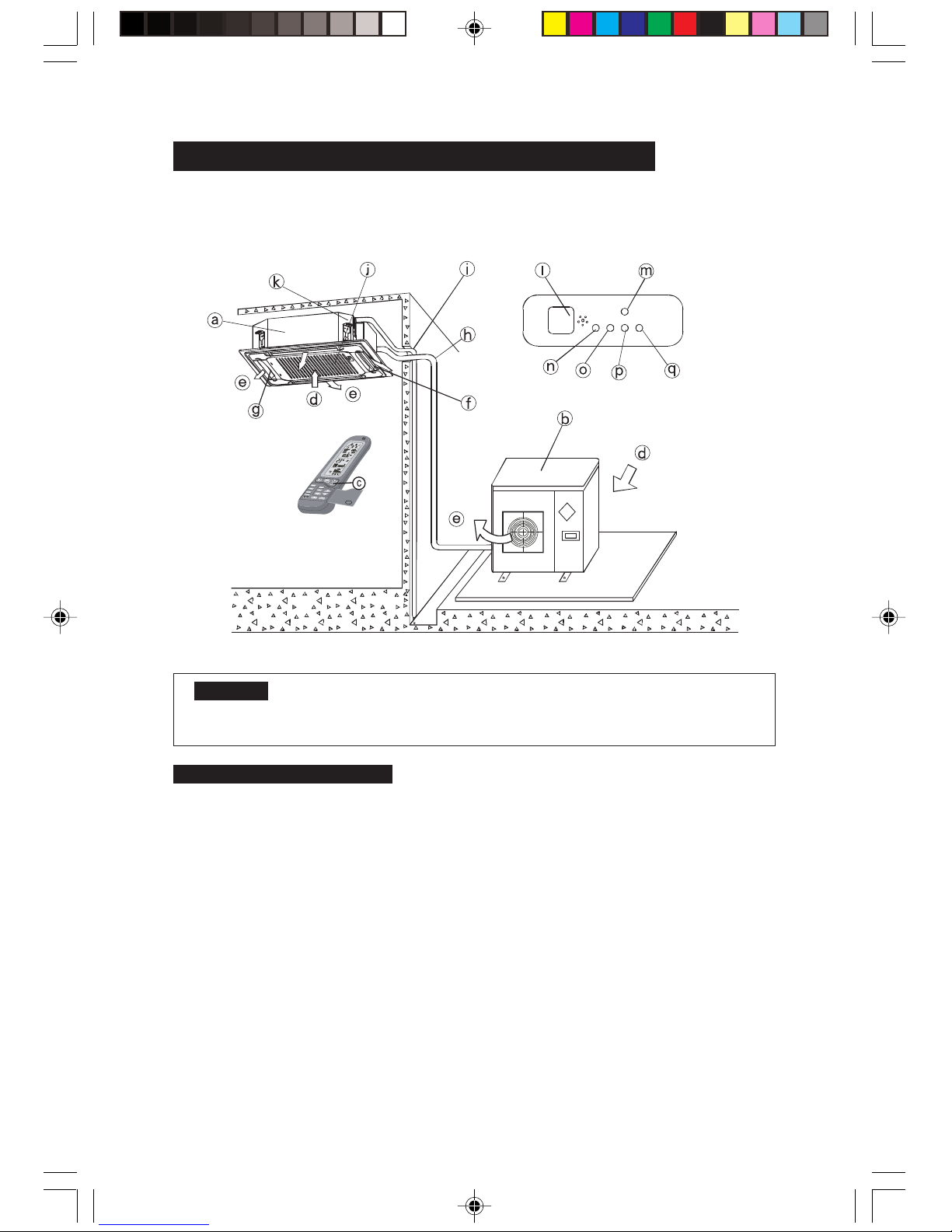
PARTS NAMES AND THEIR FUNCTIONS
The air conditioner consists of the indoor unit , the outdoor unit , the connecting pipe and the remote
controller.
NOTICE
This chart is based on KN-27SH, so, a few differences may exist on the outlook and functions
from yours.
NAMES AND FUNCTIONS
a) Indoor unit b) Outdoor unit
c) Remote controller d) Air-in
e) Air-out f) Air outlet
g) Air flow louver (at air outlet) h) Connecting pipe
i) Drain hose j) Air inlet (with air filter in it)
k) Drain pump (drain water from indoor unit) l) Infrared signal receiver
m)Temporary button n) Power supply indicator
o) Operation indicator
p) Timer indicator
q) Heat indicator
SZ000288/En 06/22/2004, 5:07 PM4
Page 6

4
OPERATION ATTENTION
NOTICE
• Please read this “Owner’s Manual” carefully operation.
• This air conditioner is designed to provide comfortable circumstances and to guarantee the
functions described in this manual only.
1. CHECK BEFORE OPERATION
• Check that the ground wiring is not broken off and is connected well.
• Check that the air filter is installed well.
• Clean the air filter at first after a long time rest. If you plan to use it continuously, please clean it once
the other week. (Refer to the chapter “Maintenance”)
• Be sure that air inlet and air outlet of the indoor and outdoor units are not blocked.
2. SAFETY INFORMATION
• To avoid the risk of serious electrical shock. Never sprinkle or spill water or liquid on the indoor unit
and the remote controller.
• To avoid the risk of fire, please keep inflammables such as hair-glue, spray lacquer and gasoline
away from the air conditioner.
• Don’t touch the grill while the airflow louver is running. Or your finger or machine parts may be hurt.
• Don’t replace the blown fuse with insulted one or other wiring. It may do harm to the unit or cause
fires.
• Don’t put hands or objects into the air outlet and inlet. These units contain a fan running at a high
speed. Contacting with the moving fan will cause serious injury.
• Don’t remove the fan hood from the outdoor unit, without which it is very dangerous.
• Please use the ON/OFF button on the remote controller to start or stop the air conditioner, instead of
the main power switch.
• Don’t let children play with the air conditioner.
• Don’t attempt to service the unit yourself, please consult qualified person.
• Because linked to the ground , this unit has a double-security function, which ensures safety for
normal replacement and cleaning. To guarantee your absolute safety, however, please turn off the
power before any routine maintenance.
3. AIR CONDITIONER OPERATING CONDITIONS
(According to T1 temperature condition)
NOTICE
If the air conditioner is used outside of the above conditions, malfunctions may be caused.
Outdoor Temperature: 21
o
C to 43oC
COOLING
CAUTION !
Room temperature humidity must be less than 80%. If the air conditioner operates in
excess of this figure, the surface of the air conditioner may attract condensation.
At this time, HIGH wind speed is advised.
HEATING
Outdoor Temperature: -5
o
C to 21oC R22
Outdoor Temperature: -9
o
C to 21oC R407C/R410A
SZ000288/En 06/22/2004, 5:07 PM5
Page 7
5
ADJUST IT UP AND DOWN
TEMPORARY
BUTTON
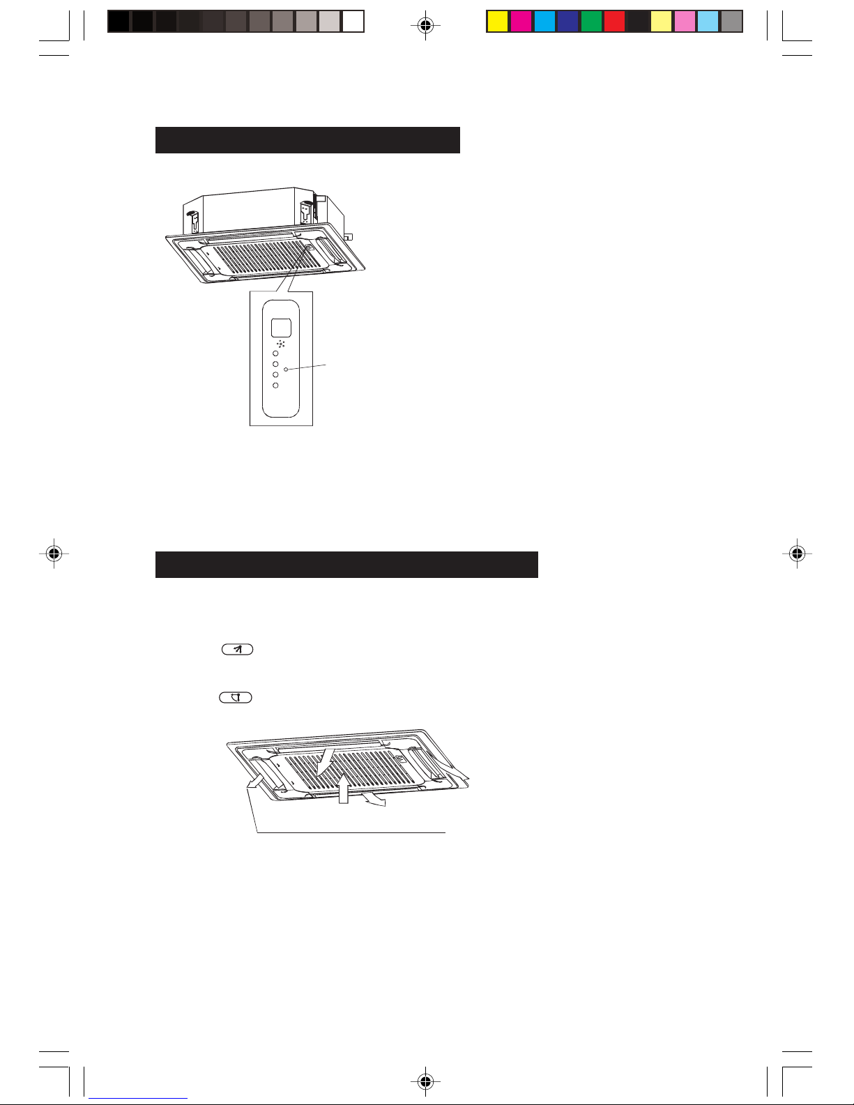
TEMPORARY OPERATIONS
This function is used to operate the unit
temporarily in case you misplace the remote
controller or its batteries are exhausted. Two
modes including mandatory HEAT and mandatory
COOL can be selected through the TEMPORARY
BUTTON on the air inlet grill control box of the
indoor unit. Once you push this button, the air
conditioner will run in such order mandatory HEAT
mandatory COOL, OFF and back to mandatory
HEAT.
1. Mandatory HEAT
The HEAT lamp (q) is lit, and the air conditioner
will run under HEAT mode.
2. Mandatory COOL
The air conditioner will run under COOL mode.
3. OFF
The OPERATION lamp (o) goes off, and the air
conditioner will be STAND-BY.
ADJUSTING AIR FLOW DIRECTION
While the unit is in operation, you can adjust the air flow louver to change the flow direction and
naturalize the room temperature evenly. Thus you can enjoy it more comfortably.
1. Set the desired air flow direction.
Push the
button to adjust the louver to the desired position and push this button again to
maintain the louver at this position.
2. Adjust the air flow direction automatically.
Push the
button, the louver will swing automatically.
While this function is set, the swing motor of indoor unit runs, otherwise, the swing motor doesn’t run.
The swing scale of every side is 30°.
SZ000288/En 06/22/2004, 5:07 PM6
Page 8

6
HINTS FOR ECONOMICAL OPERATION
The following should be noticed ensure an economical operation. (Refer to corresponding chapter for
details)
• Adjust the air flow direction properly to avoid winding toward your body.
• Adjust the room temperature properly to get a comfortable situation and to avoid supercooling and
superheat.
• In cooling, close the curtains to avoid direct sunlight.
• To keep cool or warm air in the room, never open doors or windows more often than necessary.
• Set the timer for the desired operating time.
• Never put obstructions near the air outlet or the air inlet. Or it will cause lower efficiency, even a
sudden stop.
• If you don’t plan to use the unit for a long time, please disconnect power and remove the batteries
from the remote controller. When the power switch is connected , some energy will be consumed ,
even if the air conditioner isn’t in operation. So please disconnect the power to save energy. And
please switch the power on 12 hours before you restart the unit to ensure a smooth operation.
• A clogged air filter will reduce cooling or heating efficiency, please clean it once two weeks.
MAINTENANCE
CAUTION
• Maintenance work can only be performed by specialized maintenance personnel.
• The main power switch must be turned off before doing electrical connections or cleaning of air filter.
• Do not use water or air of temperature above 50°C to clean air filter or face panel.
METHOD FOR CLEANING AIR FILTER
• The air filter can prevent the dust or other particulate from going inside. In case of blockage of the
filter, the working efficiency of the air conditioner may greatly decrease. Therefore, the filter must be
cleaned once two weeks during long time usage.
• If the air conditioner is positioned in a dust place, the cleaning frequency of the air filter must be
increased.
• If the accumulated dust is too heavy to be cleaned ,please replace the filter with a new one (replaceable air filter is an optional fitting ).
1. Open the air-in grill
Push the grill switches towards the middle simultaneously as indicated in sketch A. Then pull down
the air-in grill.
Cautions: The control box cables, which are originally connected with the main body electrical
terminators, must be pulled off before doing as indicated above.
SZ000288/En 06/22/2004, 5:07 PM7
Page 9
7
2. Take out the air-in grill (together with the air filter shown in sketch B)
Pull the air-in grill down at 45° and lift it up to take out the grill.
3. Dismantle the air filter.
4. Clean the air filter (Vacuum cleaner or pure water may be used to clean the air filter. If the dust
accumulation is too heavy, please use soft brush and mild detergent to clean it and dry out in cool
place).
MAINTENANCE
• The air-in side should face up when using vacuum cleaner.
• The air-in side should face down when using water.
Cautions: Do not dry out the air filter under direct sunshine or with fire.
5. Re-install the air filter.
6. Install and close the air-in grill in the reverse order of step 1 and 2 and connect the control box cables
to the corresponding terminators of the main body.
CLEANING THE AIR OUTLET AND THE PANEL
• Use a dry cloth to wipe it.
• Pure water or mild detergent may be used if it is very dirty.
CAUTIONS
• Do not use benzene, thinner, polishing power, or similar solvents for cleaning. These may cause the
surface to crack or deform.
• To avoid the risk of electrical shock or fire, do not let water fall into the indoor unit.
• Never wipe the air flow louver violently.
• An air conditioner without air filter cannot expel the dust out of the room, which would cause
malfunctions by accumulation.
THE MAINTENANCE OF THE OUTDOOR UNIT
1. Injures may happen by improper operations because of the sharp blade of some plates and the
freezer.
2. Check the air outlet and the air inlet of the outdoor unit regularly to ensure that they are not chocked
by filth or soot.
3. The coil pipe and other parts of the outdoor unit should also be checked regularly. Please contact with
your local dealer.
IF YOU DO NOT PLAN TO USE THE UNIT FOR A LONG TIME
• Operate the fan for about half a day to dry the inside of the unit. (Refer to the COOLING /HEATING
(cooling only type without)/FAN ONLY chapter)
• Turn off the unit with the
button on the remote controller. Then disconnect the power.
MAINTENANCE
• When the power switch is connected, some energy will be consumed, even if the unit is not in
operation. So please disconnect the power to save energy.
• Remove the batteries from the remote controller.
• A degree of filth will be accumulated due to certain performance after several seasons of operation.
So special maintenance is advised.
SZ000288/En 06/22/2004, 5:07 PM8
Page 10
8
RESTART AFTER A LONG TIME
1. Check before operation
• Check that air outlets of the outdoor and indoor are not blocked.
• Check that the ground wiring is not broken off and is connected well.
2. Restore the air filter and the front panel
The air filter and the front panel must be fixed to the original position after having been cleaned.
3. Connect the main power switch
To protect the air conditioner, power should be provided 12 hours before operation. Then the
OPERATION lamp on the control box of the indoor unit will flash once a second .
PHENOMENA NOT CONCERNING MALFUNCTIONS
1. No operation
• The air conditioner does not work immediately after button is pushed.
For each Mode including Power OFF and SB, a Min time delay of 3 min before Comp. restarting,
excluding Deicing Mode.
2. A white mist of chilled air is generated from the indoor unit.
• Cooling in a room with a high relative humidity (in a place with much oil mist or dusts),
• The room temperature will be uneven if there is much filth inside the indoor unit. In this case, cleaning
is necessary. This work requires qualified person.
• If the air conditioner heats right after defrosting, the water will be sent out in the form of steam.
3. Noise
A kind of continuous low sound of hiss could be heard while the air conditioner is on operation. This is
caused by Freon flowing between the indoor and outdoor units causes this.
• A kind of hiss could be heard during the time of defrosting or right after stop. This is caused by Freon
changing its flow volume or not flowing any more.
• A kind of continuous low sound of rustle could be heard while the air conditioner is on
COOLING(including AUTO)or DRYING. This is caused by the drain pump which is running .
• A kind of squeak will be heard while the air conditioner is on or off operation. This is caused by the
inflation or deflation of the plastics of the unit due to the temperature fluctuation.
4. Dusts are blown out of the indoor unit
This occurs only in the case of the first use after a longtime rest.
5. Bad odor is coming out from the indoor unit
This is because the indoor unit gives off the smell impregnated from the wall, furniture, or smoking.
6. Turning to FAN ONLY while COOLING
• To prevent the heat exchanger from frosting, turn to FAN ONLY mode automatically and the
COOLING mode will be restored before long.
• When the room temperature reaches the set one, the compressor will stop to turn to FAN ONLY. In
the HEATING mode, the process is reversed.
SZ000288/En 06/22/2004, 5:07 PM9
Page 11
9
Setting change is impossible
Symptoms Causes Reason and Disposal
The fan speed
can not be
changed.
• Check whether the MODE
indicated on the display is
AUTO.
• Check whether the MODE
indicated on the display is
DRY .
When the automatic mode is selected, the
air conditioner automatically selects the
fan speed.
When dry operation is selected, the air
conditioner automatically selects the fan
speed. The fan speed can be selected
among Cooling, Fan only and Heating.
TROUBLES AND CAUSES (concerning the unit)
1. If any or the following conditions occurs, stop the air conditioner immediately, set off the
power:
• The indicator lamps flash rapidly (two times per second), you disconnect the unit with the power
and then connect it again, but the lamp still flashes.
• Remote controller or switch operations are erratic.
• The fuse is blown frequently or the circuit breaker is tripped frequently.
• Foreign matter or water has fallen inside the unit.
• Water leaks from the indoor unit.
• Any other unusual condition is observed.
2. As for the failures besides what are mentioned above, please check the following points.
1) Inoperative
• The power supply is broken. Wait for a while.
• The power switch is set off. Set it on.
• The power fuse is blown or the circuit breaker has been tripped. Replace it.
• The batteries in the remote controller are exhausted. Replace them.
• The timer is set, and it is not the set time yet.
2) Does not cool completely, though air flows out.
• The temperature is set improperly. Either set the temperature above the room temperature while
cooling or below the room temperature while heating, for which the compressor can’t work.
• Three-minute protection feature is working.
3) Does not cool or heat well
• The air outlet or inlet of the unit is blocked. Dredge it.
• The air filter is clogged. Clean it.
• The fan speed is set to LOW.
• The louver is not at the correct position.
• Doors or windows are open. Close them to prevent external wind.
• Direct sunlight (in cooling). Please close the curtains or shades.
• Too many people in the room (in cooling). The cooling effect will be offset by the huge volume of
heat generated.
• The outdoor temperature is too high. It is normal that the cooling effect will be reduced by the
extremely high outdoor temperature.
TROUBLES AND CAUSES
(concerning the remote controller)
Before you ask for servicing or repairing, check the following points.
SZ000288/En 06/22/2004, 5:07 PM10
Page 12

The TEMP. indicator does
not come on .
The TEMP. indicator Never Comes On
Symptoms Causes Reason
• Check whether the MODE
indicated on the display is
FAN ONLY.
The temperature cannot be set
during Fan Only operation.
The remote control signal
is not transmitted when
the I/O button is pushed.
The Transmission indicator Never Comes On
Symptoms Causes Reason and Disposal
• Check whether the batteries
in the remote controller are
exhausted.
The remote control signal is not
transmitted, because the power
supply is off.
The indicator on the
display disappears after a
lapse of time.
Display Goes Off
Symptoms Causes Reason
• Check whether the timer
operation has come to an
end when the TIMER OFF is
indicated on the display.
The air conditioner operation
stops since the set time has
elapsed.
The TIMER ON indicators
go off after a lapse of
certain time.
• Check whether the timer
operation is started when the
TIMER ON is indicated on
the display.
When the time set to start the air
conditioner is reached, the air
conditioner will automatically start
and the corresponding indicator
will go off.
10
No receiving tone sounds
from the indoor unit when
the I/O button is pushed.
The signal Receiving Tone Does Not Sound
Symptoms Cause Reason
• Check whether the signal
transmitter of the remote
controller is properly directed
to the receiver of the indoor
unit when the I/O button is
pushed.
Direct the signal transmitter of
the remote controller to the
receiver of the indoor unit, and
then push the I/O button twice.
The remote controller
button do not work.
• Check the display screen of
the remote controller.
The buttons are locked.
REPARATION
If your air conditioner can not operate normally, please turn off the power immediately.
SZ000288/En 06/22/2004, 5:07 PM11
Page 13

INSTALLATION MANUAL
MANUEL D’INSTALLATION
MANUAL DE INSTALACIÓN
MANUALE DI INSTALLAZIONE
азлнкмдсаь ий млнДзйЗдЦ
For correct installation, read this manual before starting installation .
This manual may be subject to change without notice for purpose of improvement
Afin d’effectuer une installation correcte, lire le manuel avant de commencer
l’installation. Des changements peuvent être effectués dans ce manuel sans préavis,
afin d’améliorer la qualité de l’appareil
Para una correcta instalación, lea este manual antes de iniciar la instalación.
Este manual puede estar sujeto a cambios de mejora sin previo aviso.
Per un’installazione corretta, leggere il presente manuale prima di effettuare
l’installazione.
Il presente manuale può essere soggetto a modifica senza alcun tipo di preavviso al
fine di apportare dei miglioramenti.
иВК‰В ˜ВП ФУО¸БУ‚‡Ъ¸Тfl НУМ‰ЛˆЛУМВУП, ФУ˜ЪЛЪВ ФУК‡ОЫИТЪ‡ ˝ЪЛ ЛМТЪЫНˆЛЛ;
ТУı‡МflИЪВ ˝ЪЫ ЛМТЪЫНˆЛ˛ ‰Оfl ТФ‡‚УН НУЪУ˚В ПУ„ЫЪ ФУМ‡‰У·ЛЪ¸Тfl ‚
·Û‰Û˘ÂÏ.
4527454/02-Cover 06/22/2004, 5:08 PM2
Page 14

CONTENTS
1. PRECAUTIONS ............................................................................................................1
2. INSTALLATION INFORMATION ...................................................................................2
3. ATTACHED FITTINGS ..................................................................................................3
4. INSTALLATION PLACE ................................................................................................4
5. INDOOR UNIT INSTALLATION ....................................................................................5
6. OUTDOOR UNIT INSTALLATION ................................................................................8
7. INSTALL THE CONNECTING PIPE ............................................................................. 9
8. CONNECT THE DAIN PIPE ....................................................................................... 13
9. WIRING .......................................................................................................................15
10. TEST OPERATION ..................................................................................................... 20
ENGLISH
SZ000288/En 06/22/2004, 5:07 PM12
Page 15

1
PRECAUTION
SAFETY CONSIDERATIONS
Installation and servicing of air conditioning equipment can be hazardous due to system pressure and
electric components. Only trained and qualified service personnel should install, repair or service air
conditioning equipment.
All other operations should be performed by trained service personnel. When working on air conditioning
equipment, observe precautions in the literature, tags and labels attached to the unit and other safety
precautions that may apply. Follow all safety codes. Wear glasses and work gloves. Use quenching
cloth for brazing and unbrazing operations. These are fire extinguishers available for all brazing
operations.
WARNING
This manual describes the installation of specified indoor units. Do not install them connected with any
other indoor and outdoor unit. Mismatching of units and incompatibility between control devices in the
two units could lead to damage of both units.
WARNING
Before performing service or maintenance operations on system, turn off main power switch of the unit.
Electrical shock could cause personal injury.
This unit shall be installed in accordance with national wiring regulations.
WARNING
If the supply cord is damaged, it must be replaced by the manufacture or its service agent or similarly
qualified person in order to avoid a hazard.
The means for disconnection from the supply having a contact separation of at least 3 mm in all poles.
CAUTION
1. Wire the outdoor unit, then wire the indoor unit. You are not allowed to connect the air conditioner
with the power source unit wiring and piping the air conditioner is done.
2. For installation of the indoor unit, outdoor unit, and connection piping in between, follow the
instructions given in this manual as strictly as possible.
3. Installation in the following places may cause trouble. If it is unavoidable, please consult with the
dealer.
(1) A place full of machine oil.
(2) A saline place such as coast.
(3) Hot-spring resort.
(4) A place full of sulfide das.
(5) A place where there are high frequency machines such as wireless installation, welding machine,
medical facilities.
(6) A place of special environmental conditions.
SZ000288/En 06/22/2004, 5:07 PM13
Page 16

2
NOTE
Remark per EMC Directive 89/336/EEC
To prevent flicker impressions during the start of the compressor (technical process), following
installation conditions do apply.
1. The power connection for the air conditioner has to be done at the main power distribution. The
distribution has to be of a low impedance, normally the required impedance reaches at a 32 A fusing
point.
2. No other equipment has to be connected with this power line.
3. For detailed installation acceptance please refer to your contract with the power supplier, if restrictions to apply for products like washing machines, air conditioners or electrical oven.
4. For power details of the air conditioner refer to the rating plate of the product.
5. For any question contact your local dealer.
INSTALLATION INFORMATION
&To install properly, please read this “installation manual” at first.
& The air conditioner must be installed by qualified persons.
& When installing the indoor unit or its tubing, please follow this manual as strictly as possible.
& When all the installation work is finished, please turn on the power only after a thorough check.
CAUTIONS FOR THE REMOTE CONTROLLER OPERATION
& Please do not throw the remote controller or beat it.
& Please use the remote controller within the allowed distance, and keep the transmitter toward the
receiver of the indoor unit.
& Please keep the remote controller more than 1 m away from TV or stereo set.
& Never put the remote controller at the place with humid or direct sunlight, or near heaters.
INSTALLATION ORDER
1. Select the location
2. Install the indoor unit
3. Install the outdoor unit
4. Install the connecting pipe
5. Connect the drain pipe
6. Wiring
7. Test opertion
SZ000288/En 06/22/2004, 5:07 PM14
Page 17

3
ATTACHED FITTINGS
Please check whether the following fittings are of full scope. If there are some attached fittings free from
use, please restore them carefully.
Installation fittings Drainpipe Fittings
1. Expansible hook ........................................ 4 5. Out-let pipe sheath .................................. 1
2. Installation hook ........................................ 4 6. Out-let pipe clasp .................................... 1
3. Installation paper board ............................ 1 7. Tightening band ..................................... 20
4. Bolt M6X12 .............................................. 4 8. Drain elbow ............................................. 1
9. Seal ring .................................................. 1
Protect Pipe Fittings Remote controller & Its Frame
10. Wall conduit............................................. 1 12. Remote controller .................................. 1
11. Wall conduit cover ................................... 1 13. Frame .................................................... 1
1 14. Mounting screw (ST2.9 X 10-C-H) ....... 2
1 15. Alkaline by batteries (AM4).................... 2
Others
16. Owner’s manual ...................................... 1
17. Installation manual .................................. 1
18. Rcw operating manual ............................ 1
19. Rcw installation manual .......................... 1
20. One-way valve throttle ...................... 1 set
(only KN30/36/45)
SZ000288/En 06/22/2004, 5:07 PM15
Page 18

4
INSTALLATION PLACE
CAUTION
Location in the following places may cause malfunction of the machine. (If unavoidable,
please consult your local dealer)
a. There is petrolatum existing.
b. There is salty air surrounding (near the coast)
c. There is caustic gas (the sulfide, for example) existing in the air (near a hot spring).
d. The Volt vibrates violently (in the factories).
e. In buses or cabinets.
f. In kitchen where it is full of oil gas.
g. There is strong electromagnetic wave existing.
h. There are inflammable materials or gas.
i. There is acid or alkaline liquid evaporating.
j. Other special conditions.
NOTICES BEFORE INSTALLATION
1. Select the correct carry-in path.
2. Move this unit as originally packaged as possible .
3. If the air conditioner is installed on a metal part of the building ,it must be electrically insulated
according to the relevant standards to electrical appliances.
1. The indoor unit
• There is enough room for installation and maintenance.
• The ceiling is horizontal, and its structure can endure the weight of the indoor unit.
• The air outlet and the air inlet are not impeded, and the influence of external air is the least.
• The air flow can reach throughout the room.
• The connecting pipe and drainpipe could be extracted out easily.
• There is no direct radiation from heaters.
2. The outdoor unit
• There is enough room for installation and maintenance.
• The air outlet and the air inlet are not impeded, and can mot be reached by strong wind.
• It must be a dry and well ventilating place.
• The support is flat and horizontal and can stand the weight id the outdoor unit. And will no
additional noise or vibration.
• Your neighborhood will not feel uncomfortable with the noise or expelled air.
• There is no leakage of combustible air.
• It is easy to install the connecting pipe or cables.
• Determine the air outlet direction where the discharged air is not blocked.
• A place free of a leakage of combustible gases.
• In the case that the installation place is exposed to a strong wind such as seaside or high position,
secure the normal fan operation by putting the unit lengthwise along the wall or using a duct or
shield plates.
• If possible, do not install the unit where it is exposed to direct sunlight.
If necessary, install a blind that does not interfere with the air flow.
• During the heating mode, the water drained off the outdoor unit. the condensate should be well
drained away by the drain hole to an appropriate place, so as not to interfere other people or
public.
• Select the position where it will not be subject to snow drifts, accumulation of leaves or other
seasonal debris. It is important that air flow for the outdoor unit is not impeded as this will result in
reduction ion heating or cooling performance.
SZ000288/En 06/22/2004, 5:07 PM16
Page 19

5
Necessary room
outlet inlet outlet
Chart 1
ground
Drain side Tubing side
780 (Hook-location)
840 (Body)
880 (Ceiling hole)
950 (Panel)
Chart 2
(Unit: mm)
Chart 3
780 (Hook-location)
840 (Body)
880 (Ceiling hole)
950 (Panel)
Note: 24/27/30 Series A 260mm
36/45 Series A 330mm
INDOOR UNIT INSTALLATION
1. Install the main body
A.The existing ceiling (to be horizontal)
a. Please cut a quadrangular hole of 880X880mm in the ceiling according to the shape of the installation
paper board. (Refer to Chart 3, 4)
• The center to the hole should be at the same position of that of the air conditioner body.
• Determine the lengths and outlets of the connecting pipe, drainpipe and cables.
• To balance the ceiling and to avoid vibration, please enforce the ceiling when necessary.
b. Please select the position of installation hooks according to the hook holes in the installation board.
• Drill four holes of M12mm, 45-50mm deep at the selected positions on the ceiling. Then embed the
expansible hooks (fittings).
• Face the concave side of the installation hooks towards the expansible hooks. Determine the length
of the installation hooks from the height of ceiling, then cut off the unnecessary part.
The length could be calculated from Chart 5:
Length= H-181+L ( in general, L=100mm and is half of the whole length of the installation hook)
c. Please adjust the hexangular nuts on the four installation hooks evenly, to ensure the balance of the
body.
• If the drainpipe is away, leakage will be caused by the malfunction of the water-level switch.
• Adjust the position to ensure the gaps between the body and the four sides of ceiling are even. The
body’s lower part should sink into the ceiling for 10-12mm (Refer to Chart 5).
• Location the air conditioner firmly by wrenching the nuts after having adjusted the body’s position
well.
SZ000288/En 06/22/2004, 5:07 PM17
Page 20

6
Chart 8
Body
Hook
Ceiling
Panel
Chart 4
H (Ceiling height)
Body
Ceiling
Chart 5
Chart 6
Body
Body M6X12
Central hole
Installation paper
board
Chart 7
Grid
switch
Chart 9 Chart 10
Note: 24/27/30 Series B 240mm
36/45 Series B 310mm
Nut
B. New built houses and ceilings
a. In the case of new built house, the hook can be embedded in advance (refer to the A. B mentioned
above).
But it should be strong enough to bear the indoor unit and will not become loose because of concrete
shrinking.
b. After installing the body, please fasten the installation paper board onto the air conditioner with bolts
(M6X12) to determine in advance the sizes and positions of the hole opening on ceiling.
Please first guarantee the flatness and horizontal of ceiling when installing it.
Refer to the A. a mentioned above for others.
c. Refer to the A. c mentioned above for installation.
d. Remove the installation paper board.
CAUTIONS
After completion of installing the body, the four bolts (M6X12) must be fastened to the air conditioner to
ensure the body is grounded well.
2. Install the panel
CAUTIONS
• Never put the panel face down on floor or against the wall, or on bulgy objects.
• Never crash or strike it.
(1)Remove the inlet grid
a Slide two grid swiches toward the middle at the same time, and then pull them up. (Refer to chart 8)
b. Draw the grid up to an angle of about 45°, and remove it. (Refer to chart 9)
(2)Remove the installation covers at the four corners.
Wrench off the bolts, loose the rope of the installation covers, and remove them. (Refer to chart 10)
SZ000288/En 06/22/2004, 5:07 PM18
Page 21

7
Outlet joint
Tubing joint
Hookpanel
Waterreceiver
Swing Motor
Hookbolt
crossscrewdriver
Chart 11
body
ceiling
panel sponge
panel
panel foam 1
air out
outlet foam
fan
bukpeshku i
panelit 2
Chart 12
Chart 13
leakage
ceiling
pollution
water condensation
Gap not allowed
Loosen
upper nut
Adjust
lower nut
Chart 14
Installation
cover’s rope
Tap screw
Chart 15
Slide the four
sliders in the
corresponding
channel when
installing the
cover.
(3)Install the panel
a. Align the swing motor on the panel to the tubing joints of the body properly. (Refer to chart 11)
b. Fix hooks of the panel at swing motor and its opposite sides to the hooks of corresponding water
receiver. (Refer to chart 11①) Then hang the other two panel hooks onto corresponding hangers of
the body. (Refer to chart 11➁)
CAUTION
c. Adjust the four panel hook screws to keep the panel horizontal, and screw them up to the ceiling
evenly. (Refer to chart 11➂)
d. Regulate the panel in the direction of the arrow in Chart 11➃ slightly to fit the panel’s center to the
center of the ceiling’s opening. Guarantee that hooks of four corners are fixed well.
e. Keep fastening the screws under the panel hooks, until the thickness of the sponge between the body
and the panel’s outlet has been reduced to about 4~6mm. The edge of the panel should contact with
the ceiling well. (Refer to chart 12)
• Malfunction described in Chart 13 can be caused by inappropriate tightness the screw.
• If the gap between the panel and ceiling still exists after fastening the screws, the height of the indoor
unit should be modified again. (Refer to chart 14-left)
• You can modify the height of the indoor unit through the openings on the panel’s four corners, if the
lift of the indoor unit and the drainpipe is not influenced. (Refer to chart 14-right)
(4)Hang the air-in grid to the panel, then connect the lead terminator of the swing motor and that
of the control box with corresponding terminators on the body respectively.
(5)Relocate the air-in grid in the procedure of reversed order.
(6)Relocate the installation cover.
a. Fasten the rope of installation cover on the bolt of the installation cover. (Refer to chart 15-left)
b. Press the installation cover into the panel slightly. (Refer to chart 15-right)
Do not coil the wiring of the swing motor into the seal sponge.
SZ000288/En 06/22/2004, 5:07 PM19
Page 22

X
8
Strong wind
Chart 16
(Wall or obstacle)
air inlet
air inlet
air outlet
maintain channel
Chart 17
Fix with
bolt
Necessary wide
Deep
foundation
Chart 18
OUTDOOR UNIT INSTALLATION
CAUTIONS
• Keep this unit away from direct radiation of the sun or other heaters.
If unavoidable, please cover it with a shelter.
• In places hear coast or with a high attitude where the wind is violent, please install the outdoor unit
against the wall to ensure normal performance.
Use a baffle when necessary.
• In the case of extremely strong wind, please prevent the air from flowing backwards into the outdoor
unit. (Refer to chart 16)
• Locate the outdoor unit as close to the indoor unit as possible.
NECESSARY ROOM FOR installation and maintenance
(Refer to chart 17, chart 18)
If possible, please remove the obstacles nearby to prevent the performance from being impeded by too
little of air circulation.
The minimum distance between the outdoor unit and obstacles described in the installation chart does
not mean that the same is applicable to the situation of an airtight room. Leave open two of the three
directions (A,B,C).
MOVING AND INSTALLING
• Since the gravity center of this unit is not at its physical center, so please be careful when lifting it with
a sling.
• Never hold the air-in of the outdoor unit to prevent it from deforming.
• Do not touch the fan with hands or other objects.
• Do not lean it more than 45°, and do not lay it sidelong.
• Please fasten the feet of this unit with bolts firmly to prevent it from collapsing in case of earthquake
or strong wind.
SZ000288/En 06/22/2004, 5:07 PM20
Page 23

9
Use frozen oil
Bend the pipe with thumb
Chart 19
Min-radius 100m
Make the end
straight
Chart 21Chart 20
INSTALL THE CONNECTING PIPE
CAUTIONS
check whether the height drop between the indoor unit and outdoor unit , the length of refrigerant pipe,
and the number of the bends meet the following requirements:
The max height drop .................................................................................................................. 20m.
(If the height drop is more than 10m, you had better put the outdoor unit over above the indoor unit.)
The length of refrigerant pipe ...................................................................................... less than 30m.
The number of bends ...................................................................................................... less than 15
CAUTIONS
• Do not let air ,dust or other impurities fall in the pipe system during the time of installation .
•
The connecting pipe should not be installed until the indoor and outdoor units have been fixed already.
• Keep the connecting pipe dry, and do not let moisture in during installation .
The Procedure of Connecting Pipes
1. Measure the necessary length of the connecting pipe, and make it by the following way. (Refer
to “Connect The Pipes “ for details)
1) Connect the one-way valve restrictor in accessories to liquid tube assy, indoor unit at first (Note :only
KN-30/36/45)
2) Connect the indoor unit, then the outdoor unit.
• Bend the tubing in proper way. Do not harm to them.
CAUTION
• Daub the surface of the flare pipe and the joint nuts with frozen oil, and wrench it for 3?4 rounds with
hands before fasten the flare nuts. (Refer to chart 19)
• Be sure to use two wrenches simultaneously when you connect or disconnect the pipes .
3) The stop value of the outdoor unit should be closed absolutely (as original state ).Every time you
connect it ,first loosen the nuts at the part of stop value , then connect the flare pipe immediately (in 5
minutes ).If the nuts have been loosened for a long time ,dusts and other impurities may enter the
pipe system and may cause malfunction later .So please expel the air out of the pipe with refrigerant
(R-22) before connection .
4) Expel the air (refer to the “Expel The Air “) after connecting the refrigerant pipe with the indoor unit
and the outdoor unit. Then fasten the nuts at the repair-points.
Notices For Bendable Pipe
• The bending angle should not exceed 90º
• Bending position is preferably in the middle of the bendable pipe .The larger the bending radius the
better it is.
• Do not bend the pipe more than three times.
Bend the connecting pipe of small wall thickness (K 9.53mm)
• Cut out a desired concave at the bending part of the insulating pipe.
• Then expose the pipe (cover it with tapes after bending).
•To prevent collapsing or deforming, please bend the pipe at its biggest radius.
• Use bender to get a small radius pipes .
SZ000288/En 06/22/2004, 5:07 PM21
Page 24

Flaring the nuts
• Put the connecting tubing at the proper
position, wrench the nuts with hands, then
fasten it with a wrench. (Refer to Chart 24)
CAUTIONS
Too large torque will harm the bellmouthing and
too small will cause leakage. Please determine
the torque according to Table 2.
10
Lean Crude Burr
Chart 22 Chart 23
Chart 24
1. Cut a pipe with a pipe cutter.
2. Insert a flare nut into a pipe and flare the
pipe.
Table 2
Outside-diameter A (mm)
(mm) Mak Min
6.35 8.7 8.3
9.53 12.4 12.0
2.7 15.8 15.4
16 19.0 18.6
19 23.3 22.9
Tubing
Torque
Size
M6.35 1420-1720 N cm (144 - 176 kgf cm)
M9.53 3270-3990 N cm (333 - 407 kgf cm)
M12.7 4950-6030 N cm (504 - 616 kgf cm)
M16 6180-7540 N cm (630-770 kgf cm)
M19 9720-11860 N cm (990-1210 kgf cm)
Flaring
Use the market brass pipe
• Be sure to use the same insulating materials when you buy the brass pipe.
2. Locate The Pipes
• Drill a hole in the wall (suitable just for the size of the wall conduit, 50,53,71 series diameter is
M90mm, and 120 series diameter is M105mm in general), then set on the fittings such as the wall
conduit and its cover.
• Bend the connecting pipe and the cables together tightly with binding tapes .Do not let air in, which
will cause water leakage by condensation.
• Pass the bound connecting pipe through the wall conduit from outside .Be careful of the pipe
allocation to do no damage to the pipe.
3. Connect the pipes
4. Then ,open the stem of stop values of the outdoor unit to make the refrigerant pipe connecting
the indoor unit with the outdoor unit in fluent flow .
5. Be sure of no leakage by checking it with leak detector or soap water .
6. Cover the joint of the connecting pipe to the indoor unit with the soundproof /insulating
sheath (fittings),and bind it well the tapes to prevent leakage .
SZ000288/En 06/22/2004, 5:07 PM22
Page 25

11
Expel the air with a vacuum pump
(Refer to Chart 27)
(please refer to its manual for the way of using manifold value)
1. Loosen and remove the maintenance nuts of stop values A and B, and connect the charge hose of
the manifold value with the maintenance terminator of stop value A. (Be sure that stop values A and B
are both closed )
2. Connect the joint of the charge hose with the vacuum pump .
3. Open the Lo-lever of the manifold value completely.
4. Turn on the vacuum pump. At the beginning of pumping, loosen the maintenance terminator nut of
stop value B a little to check whether the air comes in (the sound of the pump changes, and the
indicator of compound meter turns below zero). Then fasten the nut.
5. when the pumping has finished ,close the Lo-lever of the manifold value completely and turn off the
vacuum pump.
• When you have pumped for over 15 minutes ,please confirm that the indicator of multi-meter is on
-10X10
-5
Pa (-76mHg).
6. Loosen and remove the quadrangle cover of stop values A and B to open stop value A and B
completely, then fasten them.
SZ000288/En 06/22/2004, 5:07 PM23
Page 26

12
Outdoor
unit
Gas-side
Indoor unit
Trap
Liquid side
Pipe joint
Chart 25
Chart 26
Manifold value
Multi-meter Pressure meter
-76CmHg
Lo-lever
Hi-lever
Charge hose
Charge hose
Vacuum
pump
Lo-lever
Chart 27
Joint nut
Quadrangle-cover
Chart 28
Trap body
Repair mouth
System joint
Quadrangle-lever
Linking pipe joint
Chart 29
Check-point of
indoor unit
Check-point of
outdoor unit
1) ON operation: Take off quadrangle cover,
clip the quadrangle head with a wrench
and turn it anticlockwise to the end. Then
fasten the quadrangle cover.
2) OFF operation: The operation is the same
as the ON operation, but you should turn
it clockwise this time.
7. Disassemble the charge hose from the repair-mouth of stop value A, and fasten the unit.
Operate the stop valves
• Open the value stem until it reaches the limitator. Do not open it any further.
• Fasten the stop values with a wrench or such tools.
• The wrench torque is listed in the Table 2 mentioned above.
CAUTIONS
All the stop values should be opened before test operation. Each air conditioner has two stop values of
different sizes on the side of the outdoor unit, which operate as Lo-stop value and Hi-stop value;
respectively .The ON/OFF operation is described in the left chart. (Refer to Chart 28)
CHECK THE LEAKAGE
Check all the joints with the leak detector or soap water. (refer to Chart 29)
NOTE: in the chart
A ...............Lo-stop value
B ...............Hi-stop value
C,D ........... Joints of the connecting pipe
to the indoor unit .
SZ000288/En 06/22/2004, 5:07 PM24
Page 27

13
Lean over
1/50
Constrict here
Drainpipe
Chart 30
Linking pipe
Lean over
1 / 50
Pump-pipe clasp
(the fittings)
Chart 31
Note: 24/27/30 Series C=200mm
36/45 Series C=212mm
INSULATION
• Be sure to with insulating materials cover all the exposed parts of the flare pipe joints and refrigerant
pipe on the liquid-side and the gas-side .Ensure that there is no gap between them.
• Incomplete insulation may cause water condensation.
CONNECT THE DRAIN PIPE
1. Install the drainpipe of the indoor unit .
• You can use a polyethylene tube as the drainpipe (out-dia, 37-39mm, in-dia. 32mm).It could be
bought at local market or from your dealer .
• Set the mouth of the drainpipe onto the root of the body’s pump-pipe, and clip the drainpipe and the
out-let pipe sheath (fittings) together firmly with the out-let pipe clasp (fittings).
CAUTIONS: Use your strength carefully to prevent the pump-pipe from breaking.
• The body’s pump pipe and the drainpipe (especially the indoor part) should be covered evenly with
the out-let pipe sheath (fittings) and be bound tightly with the constrictor to prevent condensation
caused by entered air.
• To prevent water from flowing backwards into the air conditioner while the air conditioner stops,
please lean the drainpipe down toward outdoor (outlet-side) at a degree of over 1/50. And please
avoid and bulge or water deposit. (Refer to chart 30. a)
• Do not drag the drainpipe violently when connecting to prevent the body from being pulled. Meanwhile, one support-point should be set every 1~1.5m to prevent the drainpipe from yielding (Refer to
chart 30. b). Or you can tie the drainpipe with the connecting pipe to fix it. (Refer to chart 30. c)
• In the case of prolonged drainpipe, you had better tighten its indoor part with a protection tube to
prevent it from loosing.
• If the outlet of the drainpipe is higher than the body’s pump joint, the pipe should be arranged as
vertically as possible. And the lift distance must be less than 200mm, otherwise the water will
overflow when the air conditioner stops. (Refer to Chart 31)
• The end of the drainpipe should be over 50 mm higher than the ground or the bottom of the drainage
chute, and do not immerse it in water. If you discharge the water directly into sewage, be sure to
make a U-form aquaseal by bending the pipe up to prevent the smelly gas entering the house
through the drain pipe.
SZ000288/En 06/22/2004, 5:07 PM25
Page 28

14
Chart 33
Pump joint
Test mouth
Body
Water-receiver
Test cover
Slow tube
Drain plug
Chart 32
Seal Drain elbow
The base pan hole
of the outdoor unit
The base pan of
outdoor unit
Seal
Drain
elbow
2. Drainage test
• Check whether the drainpipe is unhindered
• New built house should have this test done before paving the ceiling.
1) Refer to chart 32)
2) Turn on the power, and operate the air conditioner under the “COOLING “ mode. Listen to the
sound of the drain pump. Check whether the water is discharged well (a long of 1 min is allowed
before discharging, according to the length of the drain pipe), and check whether water leaks from
the joints.
CAUTIONS: If there is any malfunction, please resolve it immediately.
3) Stop the air conditioner, turn off the power, and reset the test cover to its original position.
• Imposition at all times during operation to avoid leakage.
3. Drain Elbow Installation (Cooling Only Type without)
Fit the seal into the drain elbow, then insert the drain elbow into the base pan hole of outdoor
condensate draining off the outdoor unit the heating mode.
SZ000288/En 06/22/2004, 5:07 PM26
Page 29

POWER
WIRING
SIZE
(mm2)
15
terminator
protection board
Chart 34
TYPE KN-24/27/30 SH KN-27/30 SH3 KN-36 SH KN-45 SH
PHASE 1-PHASE 3-PHASE 3-PHASE 3-PHASE
FREQUENCY 50Hz 50Hz 50Hz 50Hz
VOLT 220-240V 380V 380V 380V
CIRCUIT BREAKER/FUSE 40 20/PHASE 20/PHASE 20/PHASE
POWER WIRING
(INDOOR UNIT)
2.5 1.5 1.5 1.5
GROUND WIRING 2.5 1.5 1.5 1.5
POWER(INDOOR/OUTDOOR
2.5 1.5 1.5 1.5
CONNECTING WIRING)
STRONG ELECTRIC SIGNAL
(INDOOR/OUTDOOR 0.75 0.75 0.75 0.75
CONNECTING WIRING)
WIRING
CAUTION
1. The air conditioner should use separate power supply with rated voltage.
2. The external power supply to the air conditioner should have ground wiring, which is linked to the
ground wiring of the indoor and outdoor unit.
3. The wiring work should be done by qualified persons according to circuit drawing.
4. A disconnection device having an air gap contact separation in all active conductors should
incorporated in the fixed wiring according to the national wiring regulation.
5. Be sure to locate the power wiring and the signal wiring well to avoid cross-disturbance and their
contact with connecting pipe or stop valve body.
6. The wiring attached to this air conditioner is 6m long. Be sure to prolong it with wiring of the same
type and proper length if necessary. Generally, do not twist two wiring together unless the joint is
soldered well and covered with insulator tape.
7. Do not turn on the power until you checked carefully after wiring.
1. The Specification of Power
2. Remove the protection board
Disassemble the bolts from the maintenance board, and pull it in the direction of the arrow to remove
the protection board.
Notice: Do not scratch the surface during operation.
ATTENTION: Chart 34 is based on the standard model, which may lock a little different from your
own outdoor unit.
SZ000288/En 06/22/2004, 5:07 PM27
Page 30

MODEL INTERCONNECTING CIRCUIT BREAKER
CABLE WIRELESS (mm2) WITHOUT HEATING ELEMENT
KN 30 6x2.5 20A
KN 36 6x2.5 25A
16
OUTDOOR
INDOOR
3. ELECTRICAL CONNECTIONS
3.1 Power supply
WARNING
Electrical connection shall be made only by authorized electricians and in accordance with local
electrical requirements and codes. The system must be grounded.
Single-phase models and three phase models are available; for each of them, the necessary wiring
diagram is shown. connect the unit to the main power supply as for its applicable wiring diagram.
a) Single-phase models (See figure 35)
The main power supply cable must be HO5VV-K5G-type and contain 3X4 mm
2
leads.
b) Three-phase models (See Figure 36)
The main power supply cable must be HOVV-K5G- type and contain 5X2.5mm
2
leads.
WARNING
On unit with scroll type compressors, it is mandatory to listen to compressor operation upon initial
startup. Should there be an unusual noise in operation, it is necessary to interchange the phases at the
power supply connection.
1. Outdoor unit
2. Inter connecting cable
3. Power supply cord
4. Semi-automatic switch
5. Indoor unit
6. Display Quick connector
7. Display control unit
8. Wireless Remote Control
9. Wired Remote Control(optional)
10. Remote ON/OFF Switch (by Installer)
10. Control Cable (shielded)
12. Switch ON/OFF (by installer)
Figure 35: single Phase Units: electrical Scheme power to outdoor
SZ000288/En 06/22/2004, 5:07 PM28
Page 31

17
OUTDOOR
INDOOR
HEATER
MODEL INTERCONNECTING CIRCUIT BREAKER
CABLE WIRELESS (mm
2
) WITHOUT HEATING ELEMENT
KN 30 6x2,5 3x16A
KN 36 6x2,5 3x16A
KN 46 6x2,5 3x16A
Figure 36: Three Phase Units
3.2 Interconnecting cable
The electrical cable between the indoor and outdoor units, for all models, must be HO5VV-K5G-type.
Conductors shall be of size and number as indicated in Figure 35,36. The electrical cable must be one
piece, without any joints. When installing the cable under the floor, it must be protected and isolated
from any possible contact with water. When the cable path runs through a wall or an acoustic ceiling, it
will be protected with fireproof tubing. In addition, the two units should be interconnected by a telephone
type cable, 2X0.5mm2. See applicable wiring diagram in Figure 35, 36.
1. Outdoor unit
2. Inter connecting cable
3. Power supply
4. Semi-automatic switch
5. Indoor unit
6. Display Quick connector
7. Display control unit
8. Wireless Remote Control
9. Wired Remote Control (optional)
10. Remote ON/OFF Switch (by installer)
11. Control Cable (Shielded)
12. Switch ON/OFF (by installer)
13. Heater Cable (Optional)
14. Switch ON/OFF for Heater (by installer)
SZ000288/En 06/22/2004, 5:07 PM29
Page 32

18
5-CORE Cable
RW-300/500 5X1.5mm
2
INDOOR
OUTDOOR
3-CORE Cable
3X1.5mm
2
3-CORE Cable
YZW-300/500 3X1.5mm
2
Note: The cooling only type without the link listed by broken line
KN-27 AIR CONDITIONER LINK CIRCUIT
Chart 37
POWER: 380V~50Hz
SZ000288/En 06/22/2004, 5:07 PM30
Page 33

19
3-CORE Cable
3X2.5mm
2
POWER:
220-240V~50Hz
Chart 38
5-CORE Cable
5X2.5mm
2
INDOOR
OUTDOOR
Note: The cooling only type without the link listed by broken line
KN-24/27 AIR CONDITIONER LINK CIRCUIT
SZ000288/En 06/22/2004, 5:07 PM31
Page 34

20
TSET OPERATION
1. The test operation must be carried out after the entire installation has been completed.
2. Please confirm the following points before the test operation.
• The indoor unit and outdoor unit are installed properly.
• Tubing and wiring are correctly completed.
• The refrigerant pipe system is leakage checked.
• The drainage is unimpeded.
• The ground wiring is connected correctly.
• The length of the tubing and the added stow capacity of the refrigerant have been recorded.
• The power voltage fits the rated voltage of the air conditioner.
• There is no obstacle at the outlet and inlet of the outdoor and indoor units.
• The gas-side and liquid-side stop valves are both opened.
• The air conditioner is pre-heated by turning on the power .
3. According to the user’s requirement, install the remote controller frame where the remote controller’s
signal can reach the indoor unit smoothly.
4. Test operation
• Set the air conditioner under the mode of “COOLING” with the remote controller, and check the
following points per the “Owner’s manual “. If there is any malfunction, please resolve it as per
chapter “Troubles and Cause” in the “Owner’s Manual”.
1) The indoor unit
a. Whether the switch on the remote controller works well.
b. Whether the buttons on the remote controller works well.
c. Whether the air flow louver moves normally.
d. Whether the room temperature is adjusted well.
e. Whether the indicator lights normally.
f. Whether the temporary buttons works well.
g. Whether the drainage is normal.
h. Whether there is vibration or abnormal noise during operation.
i. Whether the air conditioner heats well in the case of the HEATING /COOLING type.
2) The outdoor unit
a. Whether there is vibration or abnormal noise during operation.
b. Whether the generated wind, noise, or condensed of by the air conditioner have influenced
your neighborhood.
c. Whether any of the refrigerant is leaked.
CAUTION
A protection feature prevents the air conditioner from being activated fro approximately 3 minutes when
it is restarted immediately after shut off.
SZ000288/En 06/22/2004, 5:07 PM32
Page 35

Part No: 4527454/02
4527454/02-Cover 06/22/2004, 5:08 PM3
 Loading...