

Page 1
KN Cassette R410A Series
REFRIGERANT
R410A
COOLING ONLY
HEAT PUMP
MAY - 2006
Indoor Units Outdoor Units Indoor Units Outdoor Units
KN 24 ST OU7-24 ST KN 30 RC 3PH OU8-30T RC
KN 24 ST 3PH OU7-24T ST KN 36 ST OU10-36 ST
KN 24 RC OU7-24 RC KN 36 ST 3PH OU10-36T ST
KN 24 RC 3PH OU7-24T RC KN 36 RC OU10-36 RC
KN 30 ST OU8-30 ST KN 36 RC 3PH OU10-36T RC
KN 30 ST 3PH OU8-30T ST KN 45 ST 3PH OU10-47T ST
KN 30 RC OU8-30 RC KN 45 RC 3PH OU10-47T RC
Page 2

A
LIST OF EFFECTIVE PAGES
Revision Y06-02 Service Manual − KN Series
LIST OF EFFECTIVE PAGES
Note: Changes in the pages are indicated by a “Revision#” in the footer of each effected page
(when none indicates no changes in the relevant page). All pages in the following list represent
effected/ non effected pages divided by chapters.
Dates of issue for original and changed pages are:
Original ....... 0 ........ September 2005
Total number of pages in this publication is 136 consisting of the following:
Page
No.
Revision
No. #
Page
No.
Revision
No. #
Page
No.
Revision
No. #
Title ....................... 2
A ........................... 2
i ............................. 2
1-1 - 1-3 ................ 2
2-1 - 2-7 ................ 2
3-1 ........................ 2
4-1 - 4-3 ................ 2
5-1 - 5-24 .............. 2
6-1 - 6-2 ................ 2
7-1 - 7-4 ................ 2
8-1 ........................ 2
9-1 - 9-6 ................ 2
10-1 ...................... 2
11-1-11-36 ............. 2
12-1-12-2 .............. 2
13-1-13-36 ............ 2
14-1-14-6 .............. 2
Appendix -A(15-1) .2
• Zero in this column indicates an original page.
*Due to constant improvements please note that the data on this service manual can be modified
with out notice.
**Photos are not contractual
Page 3

i
TABLE OF CONTENTS
Revision Y06-02Service Manual - KN Series
Table of Contents
1. INTRODUCTION ...................................................................................................1-1
2. PRODUCT DATA SHEET ......................................................................................2-1
3. RATING CONDITIONS ..........................................................................................3-1
4. OUTLINE DIMENSIONS .......................................................................................4-1
5. PERFORMANCE DATA & PRESSURE CURVES ................................................5-1
6. ELECTRICAL DATA ..............................................................................................6-1
7. WIRING DIAGRAMS .............................................................................................7-1
8. ELECTRICAL CONNECTIONS .............................................................................8-1
9. REFRIGERATION DIAGRAMS .............................................................................9-1
10. TUBING CONNECTIONS ......................................................................................10-1
11. CONTROL SYSTEM .............................................................................................11-1
12. TROUBLESHOOTING ..........................................................................................12-1
13.
EXPLODED VIEWS AND SPARE PARTS LISTS .................................................13-1
14. OPTIONAL ACCESSORIES .................................................................................14-1
15. APPENDIX A .........................................................................................................15-1
Page 4

1-1
INTRODUCTION
Revision Y06-02Service Manual - KN Series
1. INTRODUCTION
1.1 General
The cassette (900X900) split ceiling mounted range comprise the ST (cooling only) and
RC (heat pump) models, as follows:
• Cooling Only KN24ST, KN30ST, KN36ST 1PH & 3PH; KN45ST 3PH units
• Heat Pump KN24RC, KN30RC, KN36RC 1PH & 3PH; KN45RC 3PH units
1.2 Main Features
The (900X900) Cassette series benefits from the most advanced technological
innovations, namely:
• R410A units
• Microprocessor control.
• Indoor spacial centrifugal fan for low noise operation
• High COP.
• Easy access to interconnecting tubing and wiring connections,
• Integral condensate water pump.
• Automatic treated air sweep.
• Easy installation and service.
1.3 Indoor Unit
The indoor unit is a ceiling mounted, and can be easily fitted to many types of
residential and commercials applications.
It includes:
• Square bended coil with hydrophilic aluminum fins.
• A large diameter centrifugal fan
• Motorized flaps
• Advanced electronic control box assembly.
1.4 Filtration
The Cassette series presents with easily accessible, and re-usable pre-filters (mesh)
1.5 Control
The microprocessor indoor controller, and an infrared remote control, supplied as
standard, provide complete operating function and programming. For further details
please refer to the Operation Manual, Appendix A.
Page 5
1-2
INTRODUCTION
Revision Y06-02 Service Manual - KN Series
1.6 Outdoor Unit
The Cassette outdoor units can be installed as floor or wall mounted units by using a
wall supporting bracket. The metal sheets are protected by anti- corrosion paint work
allowing long life resistance. All outdoor units are pre-charged. For further information
please refer to the Product Data Sheet, Chapter 2.
It includes :
• A Rotary Compressor mounted in a soundproofed compartment
• Axial fan.
• Outdoor coil with hydrophilic louver fins for RC units.
• Outlet air fan grill.
• Service valves” flare” type connection.
• Interconnecting wiring terminal block.
• Electrical phase protector (on 3PH models).
• Advanced TYPHOON PCB
1.7 Tubing Connections
Flare type interconnecting tubing to be produced on site.
For further details please refer to the Installation Manual, Appendix A.
1.8 Accessories
ASK (All Season Kit):
For low ambient working conditions in cooling, an ASK can be installed.This kit allows
cooling operation down to outdoor temp of -10 ºC by gradually controlling the outdoor
fan speed motor.
RCW Wall Mounted Remote Control
The RCW1/ RCW2 remote control is a wall mounted remote controller, for multi indoor
unit applications and functioning
For further details please refer to Optional Accessories, Chapter 14.
1.9 Inbox Documentation
Each unit is supplied with its own installation and operation manuals.
Page 6
1-3
INTRODUCTION
Revision Y06-02Service Manual - KN Series
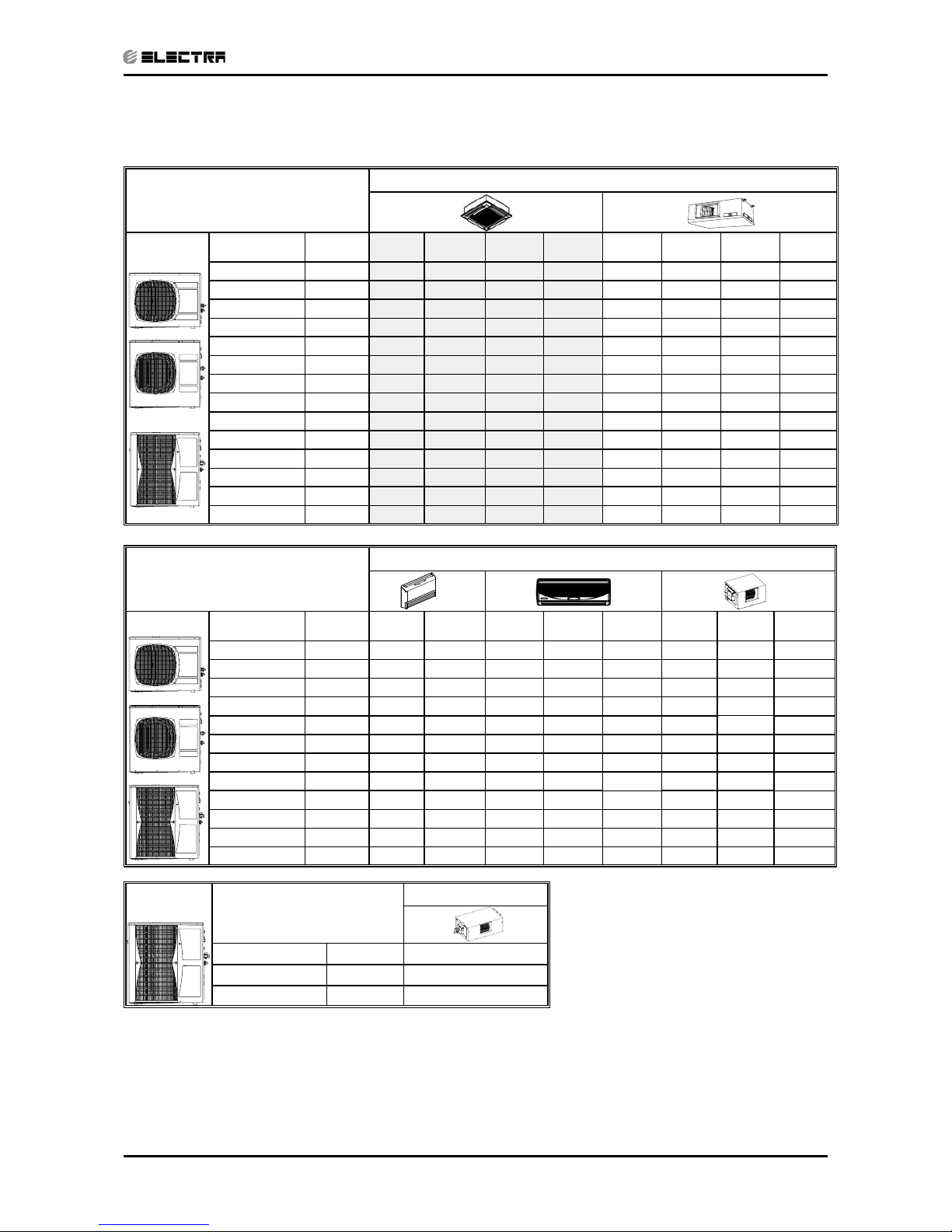
1.10 Matching Table
1.10.1 R410A
OUTDOOR UNITS
INDOOR UNITS
MODEL REF’ KN24 KN30 KN36 KN45 DNG24 DNG30 DNG36 DNG44
OU7-24ST R410A √ √
OU7-24T ST R410A √ √
OU7-24 RC R410A √ √
OU7-24T RC R410A √ √
OU8-30 ST R410A √ √
OU8-30T ST R410A √ √
OU8-30 RC R410A √ √
OU8-30T RC R410A √ √
OU10-36 ST R410A √
√
OU10-36T ST R410A √ √
OU10-36 RC R410A √ √
OU10-36T RC R410A √ √
OU10-47T ST R410A √ √
OU10-47T RC R410A √ √
OUTDOOR UNITS
INDOOR UNITS
MODEL REF’ PXD24 PXD30 WNG24 WNG30 WNG36 EMDB24 EMDB30 EMDB36
OU7-24ST R410A √ √ √
OU7-24T ST R410A √ √ √
OU7-24 RC R410A √ √* √
OU7-24T RC R410A √ √* √
OU8-30 ST R410A √ √
√
OU8-30T ST R410A √ √ √
OU8-30 RC R410A √ √ √
OU8-30T RC R410A √ √ √
OU10-36 ST R410A
√√
OU10-36T ST R410A √ √
OU10-36 RC R410A √ √
OU10-36T RC R410A √ √
OUTDOOR UNITS
INDOOR UNITS
MODEL REF’ EMDB47
OU10-47T ST R410A √
OU10-47T RC R410A √
√* - this conbination is out of the lego concept and cannot be matched with other types of indoor units.
The above table lists outdoor units and KN indoor units which can be matched together. In
addition the listed outdoor units can be matched with other types of indoor units such as ducted,
wall mounted and floor/ceiling. For further information please refer to the relevant Service
Manual.
Page 7
2-1
PRODUCT DATA SHEET
Revision Y06-02Service Manual - KN Series
2. PRODUCT DATA SHEET
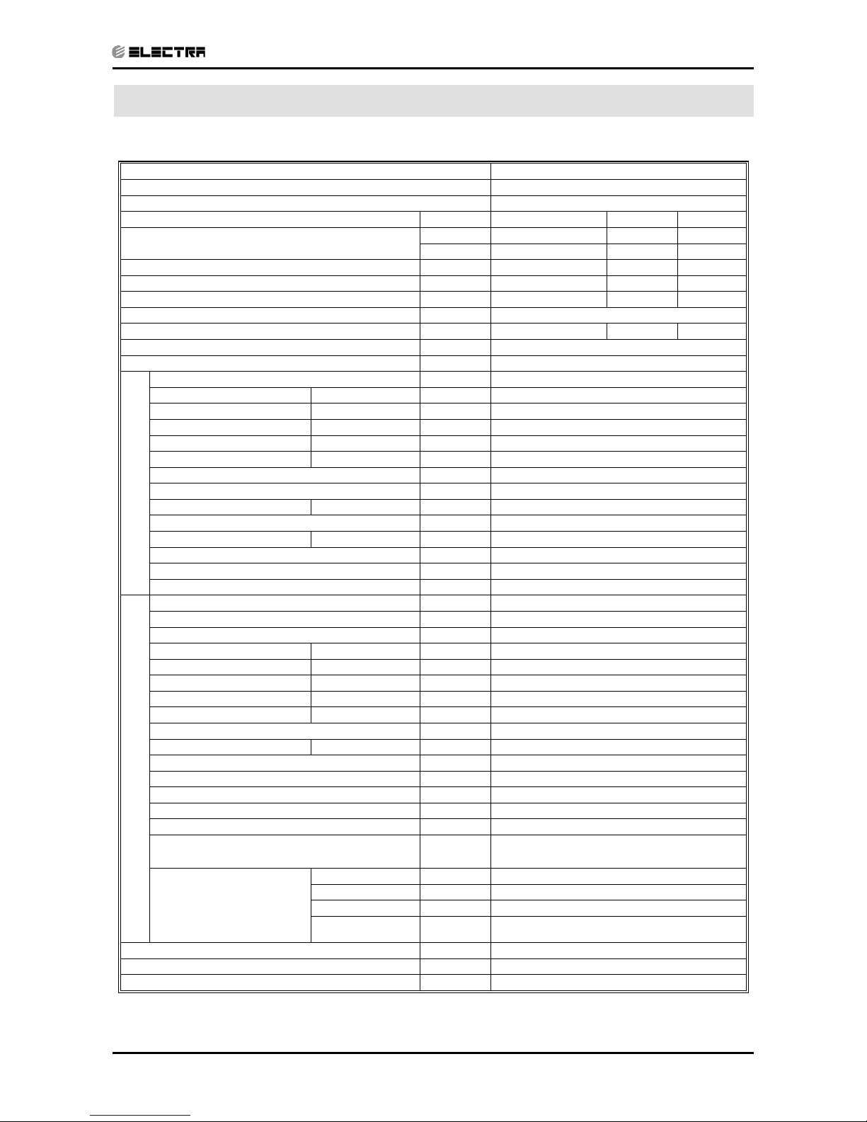
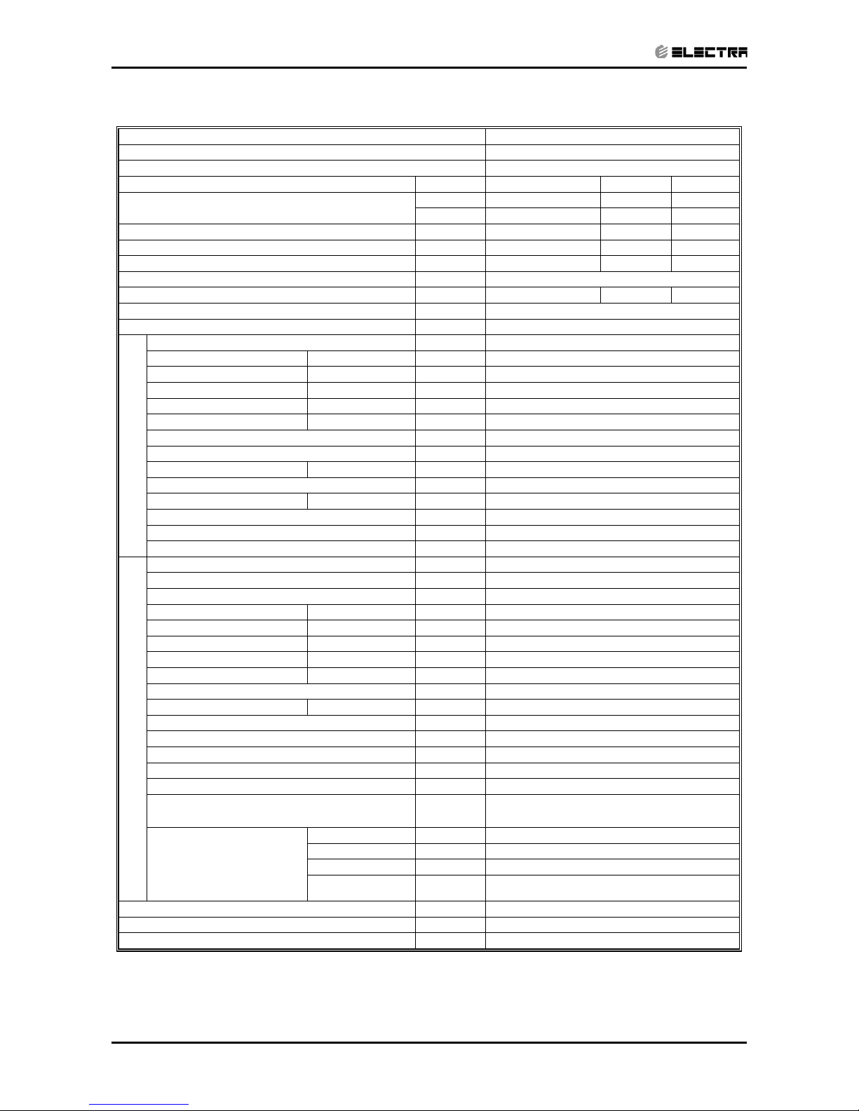
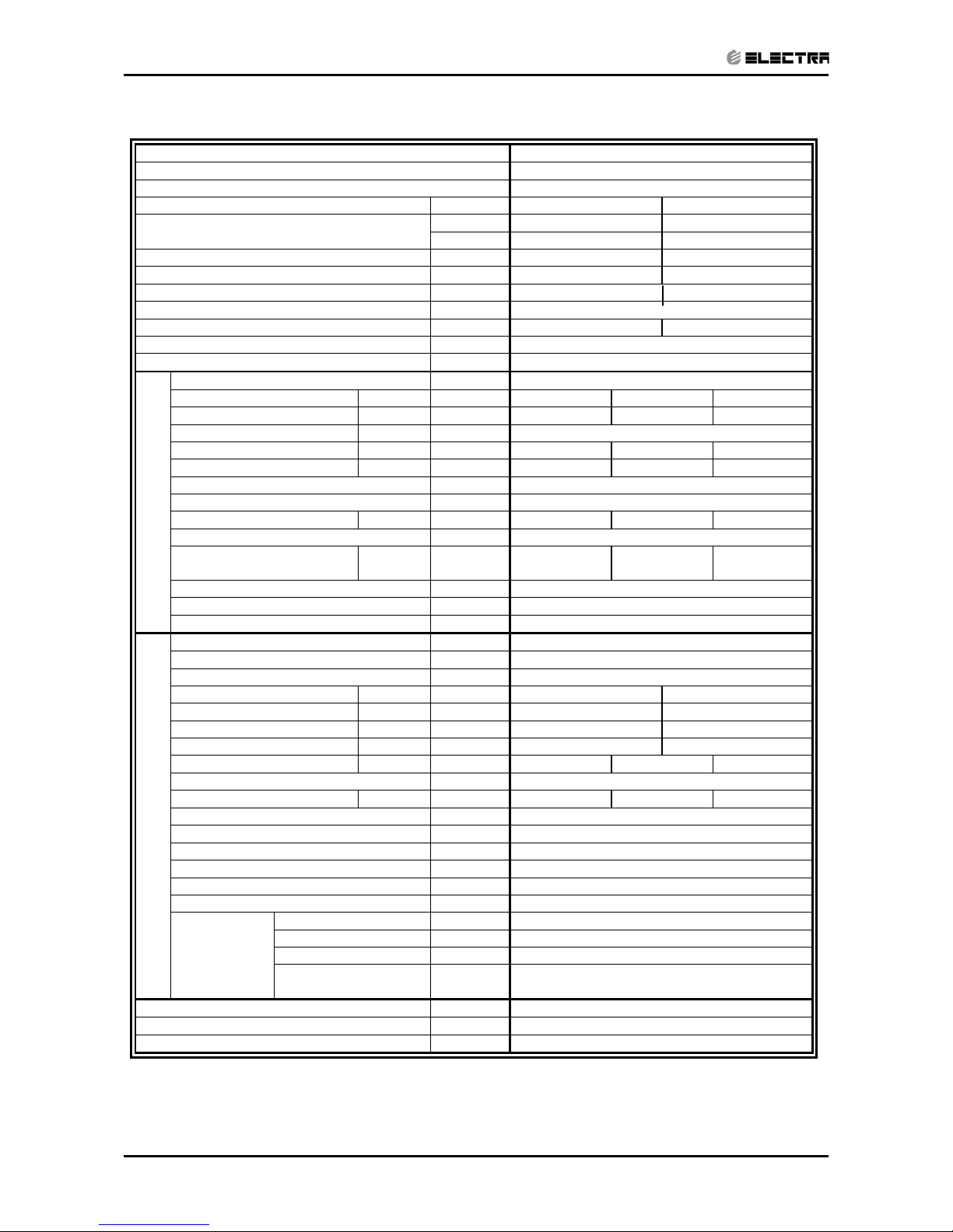
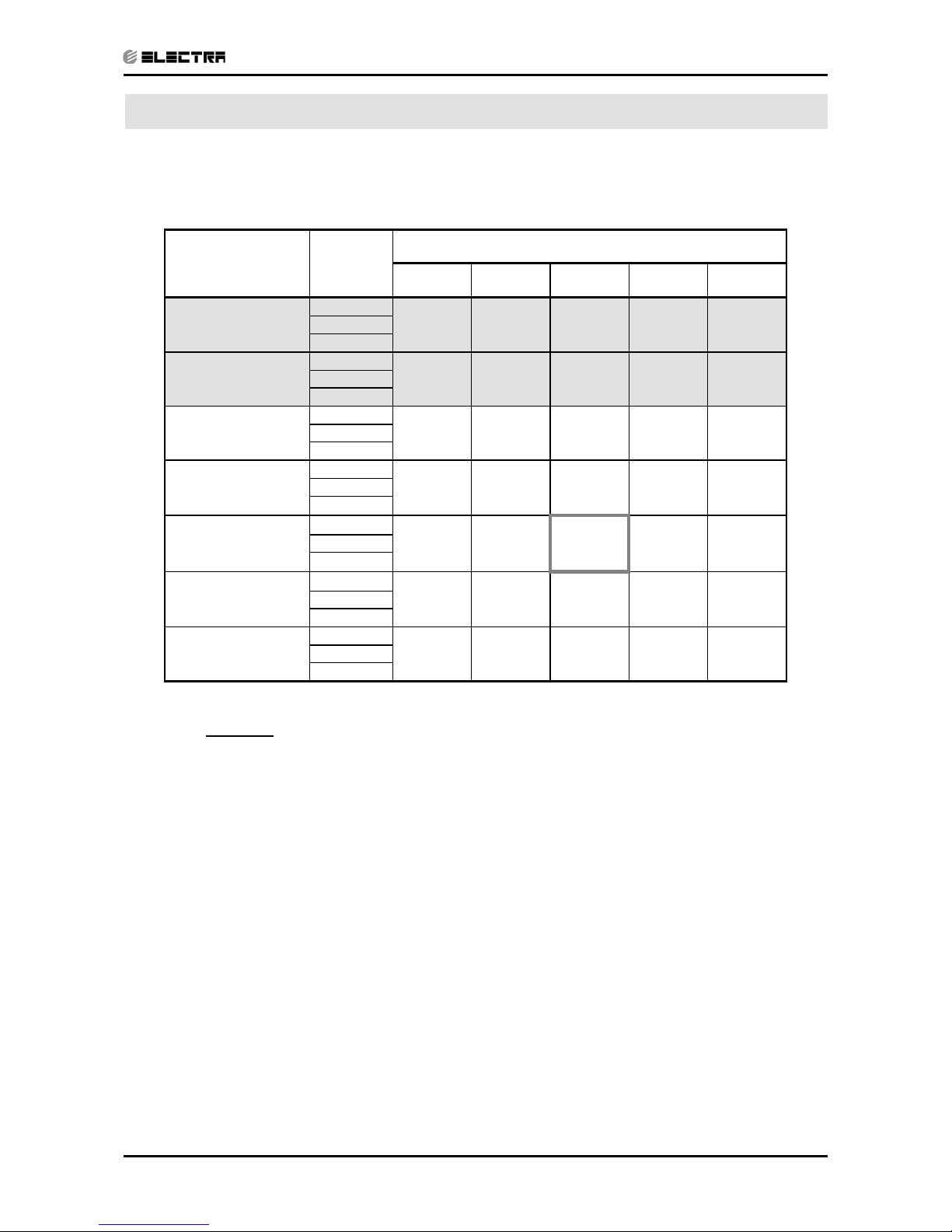
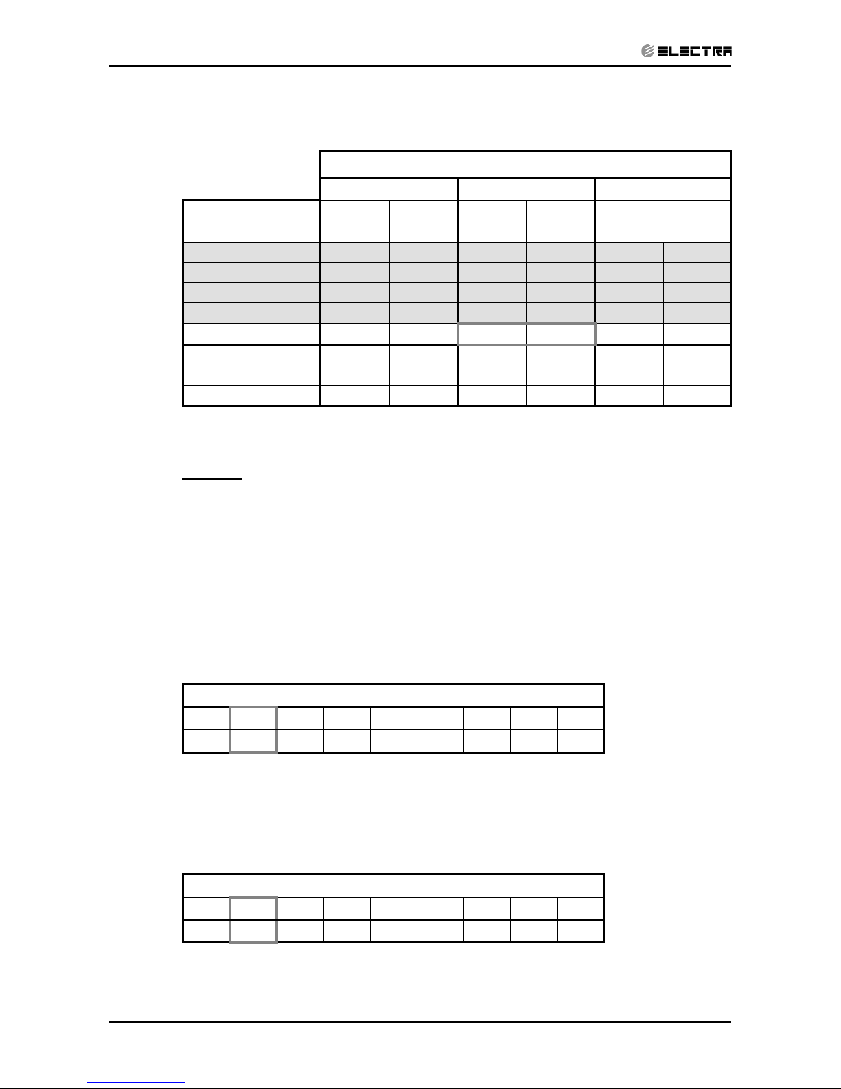
2.1 KN 24 / OU7-24 R410A
(1) Rating conditions in accordance with ISO 5151 and ISO 13253 (for ducted units) and EN 14511.
(2) Airflow in ducted units; at nominal external static pressure.
(3) Sound power in ducted units is measured at air discharge.
(4) Sound pressure level measured at 1 meter distance from unit.
Model Indoor Unit KN-24
Model Outdoor Unit OU7-24
Installation Method of Pipe Flared
Characteristics Units Cooling Only Cooling Heating
Btu/hr 23100 23100 24150
Capacity
(1)
kW 6.77 6.77 7.08
Power input
(1)
kW 2.25 2.25 2.33
EER (Cooling) or COP(Heating)
(1)
W/W 3.01 3.01 3.04
Energy efficiency class
B
B D
Power supply V/Ph/Hz 220-240V/Single/50Hz
Rated current A 9.6 9.6 9
Starting current A 63
Circuit breaker rating A 20
Fan type & quantity Centrifugal x 1
Fan speeds H/M/L RPM 570/510/460
Air flow
(2)
H/M/L m3/hr 910/800/690
External static pressure Min-Max Pa N/A
Sound power level
(3)
H/M/L dB(A) 54/50/48
Sound pressure level
(4)
H/M/L dB(A) 44/41/38
Moisture removal l/hr 2.5
Condensate drain tube I.D mm 32
Dimensions WxHxD mm 840x230x840 (Unit) / 950x46x950 (Frame)
Weight kg 36 (unit) / 6 (Frame)
Package dimensions WxHxD mm 1011x333x931 (Unit) / 1013x145x1013(Frame)
Packaged weight kg 40 (unit) / 7 (Frame)
Units per pallet units 5(Unit) / 15(Frame)
INDOOR
Stacking height units 5 Levels (unit) / 15 Levels (Frame)
Refrigerant control Capillary tube restrictor for heating)
Compressor type, model Rotary, Mitsubishi NN27VBAMT
Fan type & quantity Propeller(direct) x 1
Fan speeds H/L RPM 850
Air flow H/L m3/hr 3100
Sound power level H/L dB(A) 67
Sound pressure level
(4)
H/L dB(A) 58
Dimensions WxHxD mm 900x680x340
Weight kg 78
Package dimensions WxHxD mm 985x730x406
Packaged weight kg 82
Units per pallet Units 6
Stacking height units 2 Levels
Refrigerant type R410A
Refrigerant chargless distance kg/m 2.16kg/12.5m
Additional charge per 1 meter g/m 25
Liquid line In.(mm) 3/8"(9.53)
Suction line In.(mm) 5/8"(15.88)
Max .tubing length m. Max.30
OUTDOOR
Connections between units
Max .height
difference
m. Max.15
Operation control type Remote control
Heating elements kW
Others ASK – Factory Option
Crankcase heater (50W)
Page 8
2-2
PRODUCT DATA SHEET
Revision Y06-02 Service Manual - KN Series
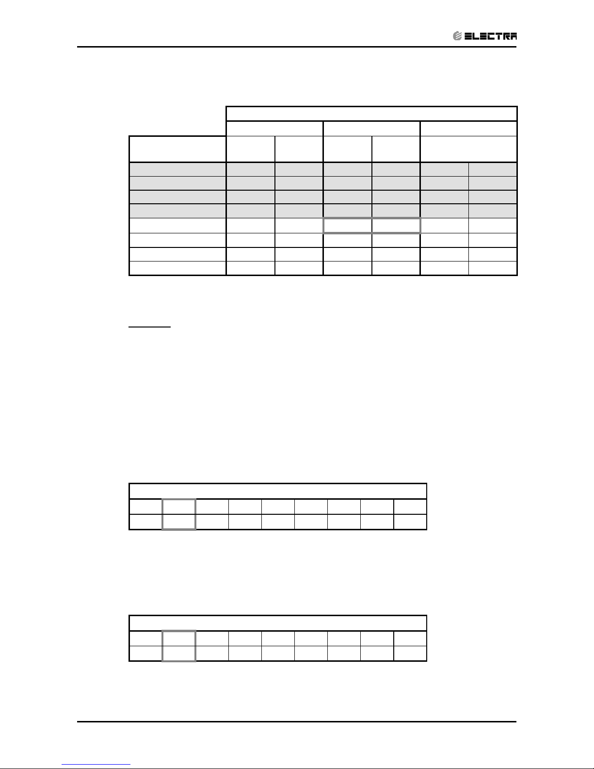
(1) Rating conditions in accordance with ISO 5151 and ISO 13253 (for ducted units) and EN 14511.
(2) Airflow in ducted units; at nominal external static pressure.
(3) Sound power in ducted units is measured at air discharge.
(4) Sound pressure level measured at 1 meter distance from unit.
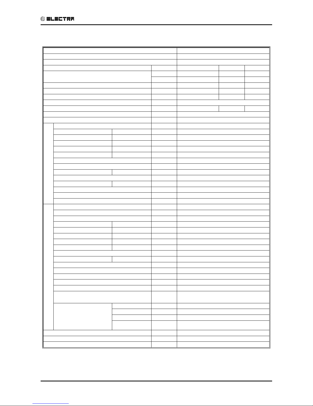
2.2 KN 24 / OU7-24T R410A
Model Indoor Unit KN-24
Model Outdoor Unit OU7-24T
Installation Method of Pipe Flared
Characteristics Units Cooling Only Cooling Heating
Btu/hr 23100 23100 24150
Capacity
(1)
kW 6.77 6.77 7.08
Power input
(1)
kW 2.25 2.25 2.33
EER (Cooling) or COP(Heating)
(1)
W/W 3.01 3.01 3.04
Energy efficiency class
B
B D
Power supply V/Ph/Hz 400V/3PH/50Hz
Rated current A 3 X 7.4 3 X 7.4 3 X 7.6
Starting current A 55
Circuit breaker rating A 3 X 16
Fan type & quantity Centrifugal x 1
Fan speeds H/M/L RPM 570/510/460
Air flow
(2)
H/M/L m3/hr 910/800/690
External static pressure Min-Max Pa N/A
Sound power level
(3)
H/M/L dB(A) 54/50/48
Sound pressure level
(4)
H/M/L dB(A) 44/41/38
Moisture removal l/hr 2.5
Condensate drain tube I.D mm 32
Dimensions WxHxD mm 840x230x840 (Unit) / 950x46x950 (Frame)
Weight kg 36 (unit) / 6 (Frame)
Package dimensions WxHxD mm 1011x333x931 (Unit) / 1013x145x1013(Frame)
Packaged weight kg 40 (unit) / 7 (Frame)
Units per pallet units 5(Unit) / 15(Frame)
INDOOR
Stacking height units 5 Levels (unit) / 15 Levels (Frame)
Refrigerant control Capillary tube (restrictor for heating)
Compressor type, model Rotary, Mitsubishi NN27VDAMT
Fan type & quantity Propeller(direct) x 1
Fan speeds H/L RPM 850
Air flow H/L m3/hr 3100
Sound power level H/L dB(A) 67
Sound pressure level
(4)
H/L dB(A) 58
Dimensions WxHxD mm 900x680x340
Weight kg 78
Package dimensions WxHxD mm 985x730x406
Packaged weight kg 82
Units per pallet Units 6
Stacking height units 2 Levels
Refrigerant type R410A
Refrigerant chargless distance kg/m 2.16kg/12.5m
Additional charge per 1 meter g/m 25
Liquid line In.(mm) 3/8"(9.53)
Suction line In.(mm) 5/8"(15.88)
Max .tubing length m. Max.30
OUTDOOR
Connections between units
Max .height
difference
m. Max.15
Operation control type Remote control
Heating elements kW
Others ASK – Factory Option
Crankcase heater (50W), 3 Phase Protector
Page 9
2-3
PRODUCT DATA SHEET
Revision Y06-02Service Manual - KN Series
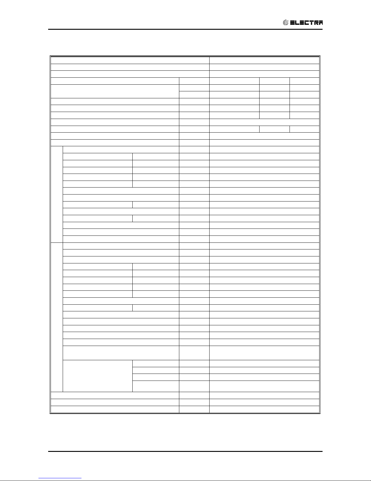
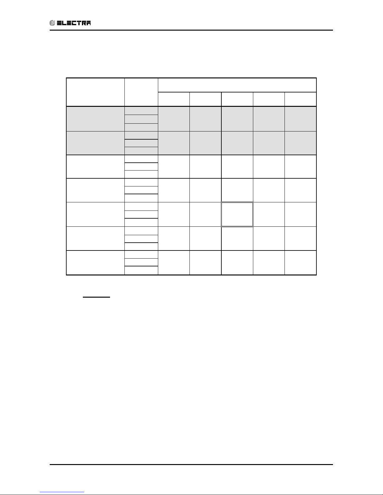
Model Indoor Unit KN-30
Model Outdoor Unit OU830
Installation Method of Pipe Flared
Characteristics Units Cooling Only Cooling Heating
Btu/hr 28,300 28,300 30,500
Capacity
(1)
kW 8.30 8.30 8.94
Power input
(1)
kW 2.94 2.94 2.88
EER (Cooling) or COP(Heating)
(1)
W/W 2.82 2.82 3.10
Energy efficiency class
C C
D
Power supply V/Ph/Hz 220-240V/Single/50Hz
Rated current A 12.3 12.3 12.3
Starting current A 80
Circuit breaker rating A 25
Fan type & quantity Centrifugal x 1
Fan speeds H/M/L RPM 740/700/620
Air flow
(2)
H/M/L m3/hr 1200/1120/985
External static pressure Min-Max Pa N/A
Sound power level
(3)
H/M/L dB(A) 61/59/56
Sound pressure level
(4)
H/M/L dB(A) 52/50/47
Moisture removal l/hr 3.2
Condensate drain tube I.D mm 32
Dimensions WxHxD mm 840x230x840 (Unit) / 950x46x950 (Frame)
Weight kg 36 (unit) / 6 (Frame)
Package dimensions WxHxD mm 1011x333x931 (Unit) / 1013x145x1013(Frame)
Packaged weight kg 40 (unit) / 7 (Frame)
Units per pallet units 5(Unit) / 15(Frame)
INDOOR
Stacking height units 5 Levels (unit) / 15 Levels (Frame)
Refrigerant control Capillary
Compressor type, model Rotary, Mitsubishi NN33VAAMT
Fan type & quantity Propeller(direct) x 1
Fan speeds H/L RPM 850
Air flow H/L m3/hr 3150
Sound power level H/L dB(A) 69
Sound pressure level
(4)
H/L dB(A) 59
Dimensions WxHxD mm 900x860x340
Weight kg 78
Package dimensions WxHxD mm 985x907x435
Packaged weight kg 82
Units per pallet Units 6
Stacking height units 2 Levels
Refrigerant type R410A
Refrigerant chargless distance kg/m 2.42kg/15m
Additional charge per 1 meter g/m 30
Liquid line In.(mm) 3/8"(9.53)
Suction line In.(mm) 5/8"(15.88)
Max .tubing length m. Max.30
OUTDOOR
Connections between units
Max .height
difference
m. Max.15
Operation control type Remote control
Heating elements kW
Others Crankcase heater (50W)
(1) Rating conditions in accordance with ISO 5151 and ISO 13253 (for ducted units) and EN 14511.
(2) Airflow in ducted units; at nominal external static pressure.
(3) Sound power in ducted units is measured at air discharge.
(4) Sound pressure level measured at 1 meter distance from unit.
2.3 KN 30 / OU8-30 R410A
Page 10
2-4
PRODUCT DATA SHEET
Revision Y06-02 Service Manual - KN Series
Model Indoor Unit KN-30
Model Outdoor Unit OU830T
Installation Method of Pipe Flared
Characteristics Units Cooling Only Cooling Heating
Btu/hr 28,300 28,300 30,500
Capacity
(1)
kW 8.30 8.30 8.94
Power input
(1)
kW 2.86 2.86 2.79
EER (Cooling) or COP(Heating)
(1)
W/W 2.9 2.9 3.20
Energy efficiency class
C C
D
Power supply V/Ph/Hz 400V/3PH/50Hz
Rated current A 3 x 5.2 3 x 5.2 3 x 5.2
Starting current A 35
Circuit breaker rating A 3 x 16
Fan type & quantity Centrifugal x 1
Fan speeds H/M/L RPM 740/700/620
Air flow
(2)
H/M/L m3/hr 1200/1120/985
External static pressure Min-Max Pa N/A
Sound power level
(3)
H/M/L dB(A) 61/59/56
Sound pressure level
(4)
H/M/L dB(A) 52/50/47
Moisture removal l/hr 3.2
Condensate drain tube I.D mm 32
Dimensions WxHxD mm 840x230x840 (Unit) / 950x46x950 (Frame)
Weight kg 36 (unit) / 6 (Frame)
Package dimensions WxHxD mm 1011x333x931 (Unit) / 1013x145x1013(Frame)
Packaged weight kg 40 (unit) / 7 (Frame)
Units per pallet units 5(Unit) / 15(Frame)
INDOOR
Stacking height units 5 Levels (unit) / 15 Levels (Frame)
Refrigerant control Capillary
Compressor type, model Rotary, Mitsubishi NN33YCAMT
Fan type & quantity Propeller(direct) x 1
Fan speeds H/L RPM 850
Air flow H/L m3/hr 3150
Sound power level H/L dB(A) 69
Sound pressure level
(4)
H/L dB(A) 59
Dimensions WxHxD mm 900x860x340
Weight kg 78
Package dimensions WxHxD mm 985x907x435
Packaged weight kg 82
Units per pallet Units 6
Stacking height units 2 Levels
Refrigerant type R410A
Refrigerant chargless distance kg/m 2.42kg/15m
Additional charge per 1 meter g/m 30
Liquid line In.(mm) 3/8"(9.53)
Suction line In.(mm) 5/8"(15.88)
Max .tubing length m. Max.30
OUTDOOR
Connections between units
Max .height
difference
m. Max.15
Operation control type Remote control
Heating elements kW
Others Crankcase heater (50W),3PH Protector
(1) Rating conditions in accordance with ISO 5151 and ISO 13253 (for ducted units) and EN 14511.
(2) Airflow in ducted units; at nominal external static pressure.
(3) Sound power in ducted units is measured at air discharge.
(4) Sound pressure level measured at 1 meter distance from unit.
2.4 KN 30 / OU8-30T R410A
Page 11
2-5
PRODUCT DATA SHEET
Revision Y06-02Service Manual - KN Series
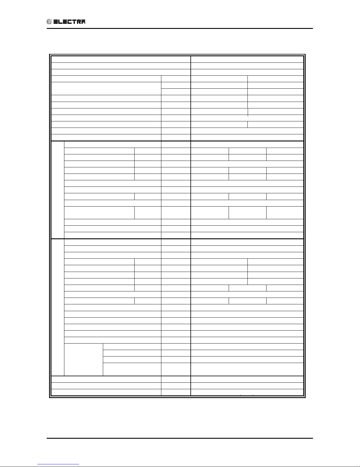
2.5 KN 36 / OU10-36 R410A
Model Indoor Unit KN 36
Model Outdoor Unit OU10-36 R410A
Installation method CASSETE
Characteristics Units Cooling Heating
Btu/hr 34,500 34,500
Capacity (1)
kW 10.10 10.10
Power input (1) kW 3.48 3.60
COP (1) W/W 2.90 2.80
Energy efficiency class C D
Power supply V/ Ph /Hz 230/50/1
Rated current A 16.2 16.3
Starting current A 92
Circuit breaker rating A 25
Fan type & quantity Centrifugal & 1
Fan speeds H/ M/ L RPM 580 540 500
Air flow (2) H/ M/ L m³/hr 1220 1125 1025
External static pressure Min-Max Pa N/A
Sound power level (3) H/ M/ L dB(A) 53 51 49
Sound pressure level (4) H/ M/ L dB(A) 46 44 42
Moisture removal L/hr 4.1
Condensate drain tube I.D mm 32
Dimensions (Unit / Frame) W/ H / D mm 840 / 950 840 / 950 300 / 46
Weight kg 48
Package dimensions
(Unit / Frame)
W/ H / D mm 1011 / 1013 931/ 1013 400 / 145
Packaged weight kg 52
Units / Frames per pallet Units 5 / 15
INDOOR
Stacking height Units / Frames Units 5 / 15
Refrigerant control Capillary tube
Compressor type, model Scroll
Fan type & quantity Axial & 2
Fan speeds H / L RPM 1150
Air flow H / L m³/hr 4150
Sound power level H / L dB(A) 70.4
Sound pressure level (4) H / L dB(A) 61.1
Dimensions W/ H / D mm 900 970 340
Weight kg 87
Package dimensions W/ H / D mm 985 1020 435
Packaged weight kg 91
Units per pallet Units 6
Stacking height Units 2
Refrigerant type R 410A
Refrigerant charges distance kg/m 2.55/15
Additional charge per 1 meter g/m 30
Liquid line In. 3/8
Suction line In. 3/4
Max. tubing length m. 50
OUTDOOR
Connections
between
units
Max. height
difference
m. 25
Operation control type LCD Remote Control
Heating elements kW 3.0
Others Crankcase heater (50W), 3 Phase Protector
(1) Rating conditions in accordance to ISO 5151 and ISO 13253 (for ducted units).
(2) Airflow in ducted units; at nominal external static pressure.
(3) Sound power in ducted units is measured at air discharge.
(4) Sound pressure level measured at 1-meter distance from unit.
Crankcase heater (50W)
Page 12
2-6
PRODUCT DATA SHEET
Revision Y06-02 Service Manual - KN Series
2.6 KN 36 / OU10-36T R410A
Model Indoor Unit KN 36
Model Outdoor Unit OU10-36T R410A
Installation method CASSETE
Characteristics Units Cooling Heating
Btu/hr 33,100 35,150
Capacity (1)
kW 9.70 10.30
Power input (1) kW 3.34 3.68
COP (1) W/W 2.90 2.80
Energy efficiency class C D
Power supply V/ Ph /Hz 400/3N/50
Rated current A 3x6.1 3x6.5
Starting current A 43
Circuit breaker rating A 3x16
Fan type & quantity Centrifugal & 1
Fan speeds H/ M/ L RPM 580 540 500
Air flow (2) H/ M/ L m³/hr 1220 1125 1025
External static pressure Min-Max Pa N/A
Sound power level (3) H/ M/ L dB(A) 53 51 49
Sound pressure level (4) H/ M/ L dB(A) 46 44 42
Moisture removal L/hr 4.1
Condensate drain tube I.D mm 32
Dimensions (Unit / Frame) W/ H / D mm 840 / 950 840 / 950 300 / 46
Weight kg 48
Package dimensions
(Unit / Frame)
W/ H / D mm 1011 / 1013 931/ 1013 400 / 145
Packaged weight kg 52
Units / Frames per pallet Units 5 / 15
INDOOR
Stacking height Units / Frames Units 5 / 15
Refrigerant control Capillary tube
Compressor type, model Scroll
Fan type & quantity Axial & 2
Fan speeds H / L RPM 1150
Air flow H / L m³/hr 4150
Sound power level H / L dB(A) 70
Sound pressure level (4) H / L dB(A) 61
Dimensions W/ H / D mm 900 970 340
Weight kg 87
Package dimensions W/ H / D mm 985 1020 435
Packaged weight kg 91
Units per pallet Units 6
Stacking height Units 2
Refrigerant type R 410A
Refrigerant charges distance kg/m 2.45/15
Additional charge per 1 meter g/m 30
Liquid line In. 3/8
Suction line In. 3/4
Max. tubing length m. 50
OUTDOOR
Connections
between
units
Max. height
difference
m. 25
Operation control type LCD Remote Control
Heating elements kW 3.0
Others Crankcase heater (50W), 3 Phase Protector
(1) Rating conditions in accordance to ISO 5151 and ISO 13253 (for ducted units).
(2) Airflow in ducted units; at nominal external static pressure.
(3) Sound power in ducted units is measured at air discharge.
(4) Sound pressure level measured at 1-meter distance from unit.
Page 13

2-7
PRODUCT DATA SHEET
Revision Y06-02Service Manual - KN Series
2.7 KN 45 / OU10-47 R410A
Model Indoor Unit KN 45
Model Outdoor Unit OU10-47T R410A
Installation method CASSETE
Characteristics Units Cooling Heating
Btu/hr 42,150 45,000
Capacity (1)
kW 12.35 13.20
Power input (1) kW 4.40 4.63
COP (1) W/W 2.80 2.85
Energy efficiency class C D
Power supply V/ Ph /Hz 400/3N/50
Rated current A 3x8.4 3x8.9
Starting current A 61
Circuit breaker rating A 3x20A
Fan type & quantity Centrifugal & 1
Fan speeds H/ M/ L RPM 810 630 570
Air flow (2) H/ M/ L m³/hr 1600 1330 1200
External static pressure Min-Max Pa N/A
Sound power level (3) H/ M/ L dB(A) 63.0 57.0 53.0
Sound pressure level (4) H/ M/ L dB(A) 55.0 49.0 46.0
Moisture removal L/hr 5.4
Condensate drain tube I.D mm 32
Dimensions (Unit / Frame) W/ H / D mm 840 / 950 840 / 950 300 / 46
Weight kg 48
Package dimensions
(Unit / Frame)
W/ H / D mm 1011 / 1013 931/ 1013 400 / 145
Packaged weight kg 52
Units / Frames per pallet Units 5 / 15
INDOOR
Stacking height Units / Frames Units 5 / 15
Refrigerant control Capillary tube
Compressor type, model Scroll
Fan type & quantity Axial & 2
Fan speeds H / L RPM 1240
Air flow H / L m³/hr 4350
Sound power level H / L dB(A) 71
Sound pressure level (4) H / L dB(A) 64
Dimensions W/ H / D mm 900 970 340
Weight kg 96
Package dimensions W/ H / D mm 985 1020 435
Packaged weight kg 100
Units per pallet Units 6
Stacking height Units 2
Refrigerant type R 410A
Refrigerant charges distance kg/m 3,00/15
Additional charge per 1 meter g/m 45
Liquid line In. 3/8
Suction line In. 3/4
Max. tubing length m. 50
OUTDOOR
Connections
between
units
Max. height
difference
m. 25
Operation control type LCD Remote Control
Heating elements kW 3.0
Others Crankcase heater (50W), 3 Phase Protector
(1) Rating conditions in accordance to ISO 5151 and ISO 13253 (for ducted units).
(2) Airflow in ducted units; at nominal external static pressure.
(3) Sound power in ducted units is measured at air discharge.
(4) Sound pressure level measured at 1-meter distance from unit.
Page 14

3-1
RATING CONDITIONS
Revision Y06-02Service Manual - KN Series
3. RATING CONDITIONS
Standard conditions in accordance with ISO 5151, ISO 13253 (for ducted units)
and EN 14511.
Cooling:
Indoor: 27
o
C DB 19oC WB
Outdoor: 35 oC DB
Heating:
Indoor: 20
o
C DB
Outdoor: 7oC DB 6oC WB
3.1 Operating Limits
Indoor Outdoor
Cooling
Upper limit 32
o
C DB 23oC WB 46oC DB
Lower limit 21
o
C DB 15oC WB 21oC DB
Heating
Upper limit 27
o
C DB 24oC DB 18oC WB
Lower limit 20
o
C DB -9oC DB -10oC WB
Voltage
1PH 198 – 264 V
3PH 360 - 440 V
Page 15
4-1
OUTLINE DIMENSIONS
Revision Y06-02Service Manual - KN Series
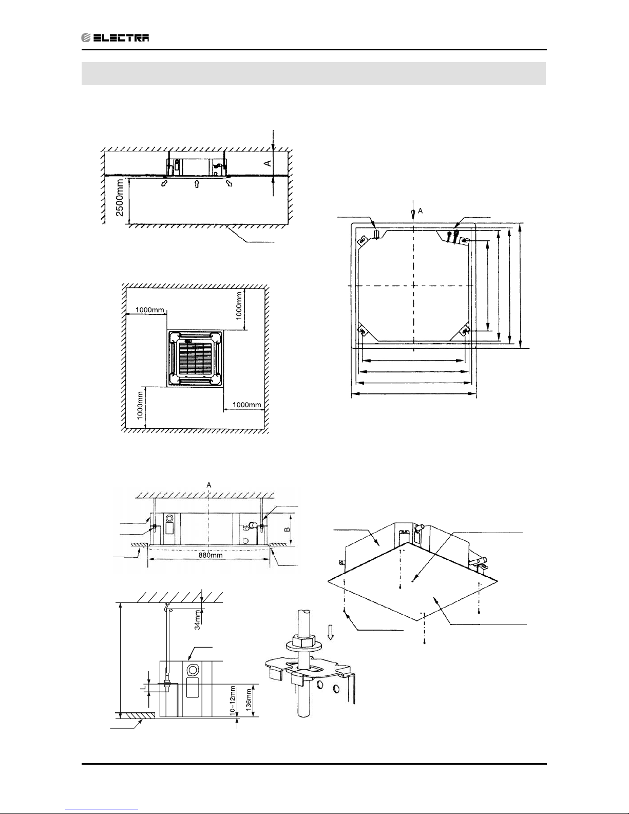
4. OUTLINE DIMENSIONS
4.1 Indoor Unit: KN 24, 30, 36, 45
Necessary room
outlet inlet outlet
Chart 1
ground
Drain side Tubing side
780 (Hook-location)
840 (Body)
880 (Ceiling hole)
950 (Panel)
Chart 2
(Unit: mm)
Chart 3
780 (Hook-location)
840 (Body)
880 (Ceiling hole)
950 (Panel)
Note: 24/27/30 Series A 260mm
36/45 Series A 330mm
Body
Hook
Ceiling
Panel
Chart 4
H (Ceiling height)
Body
Ceiling
Chart 5
Chart 6
Body
Body M6X12
Central hole
Installation paper
board
Chart 7
Note: 24/27/30 Series B 240mm
36/45 Series B 310mm
Nut
Page 16
4-2
OUTLINE DIMENSIONS
Revision Y06-02 Service Manual - KN Series
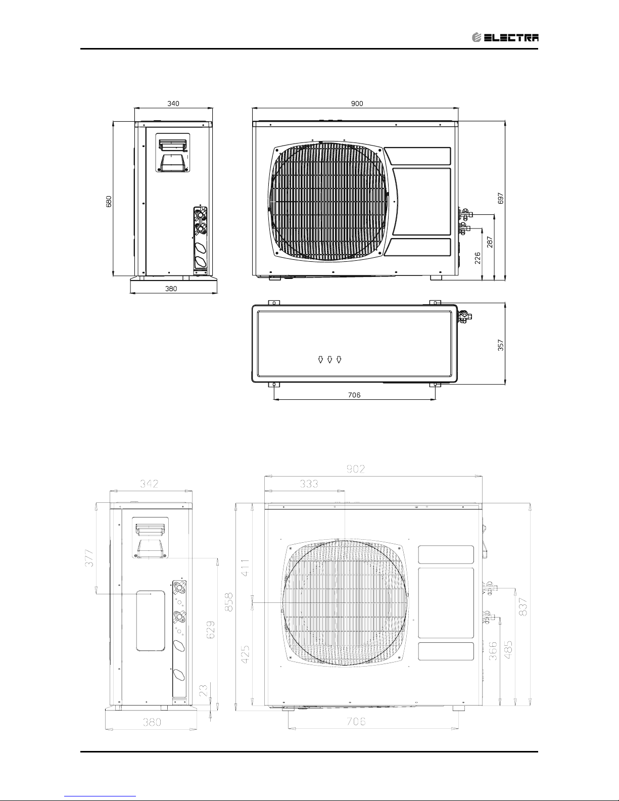
4.2 Outdoor Unit: OU7-24
4.3 Outdoor Unit: OU8-30
Page 17
4-3
OUTLINE DIMENSIONS
Revision Y06-02Service Manual - KN Series
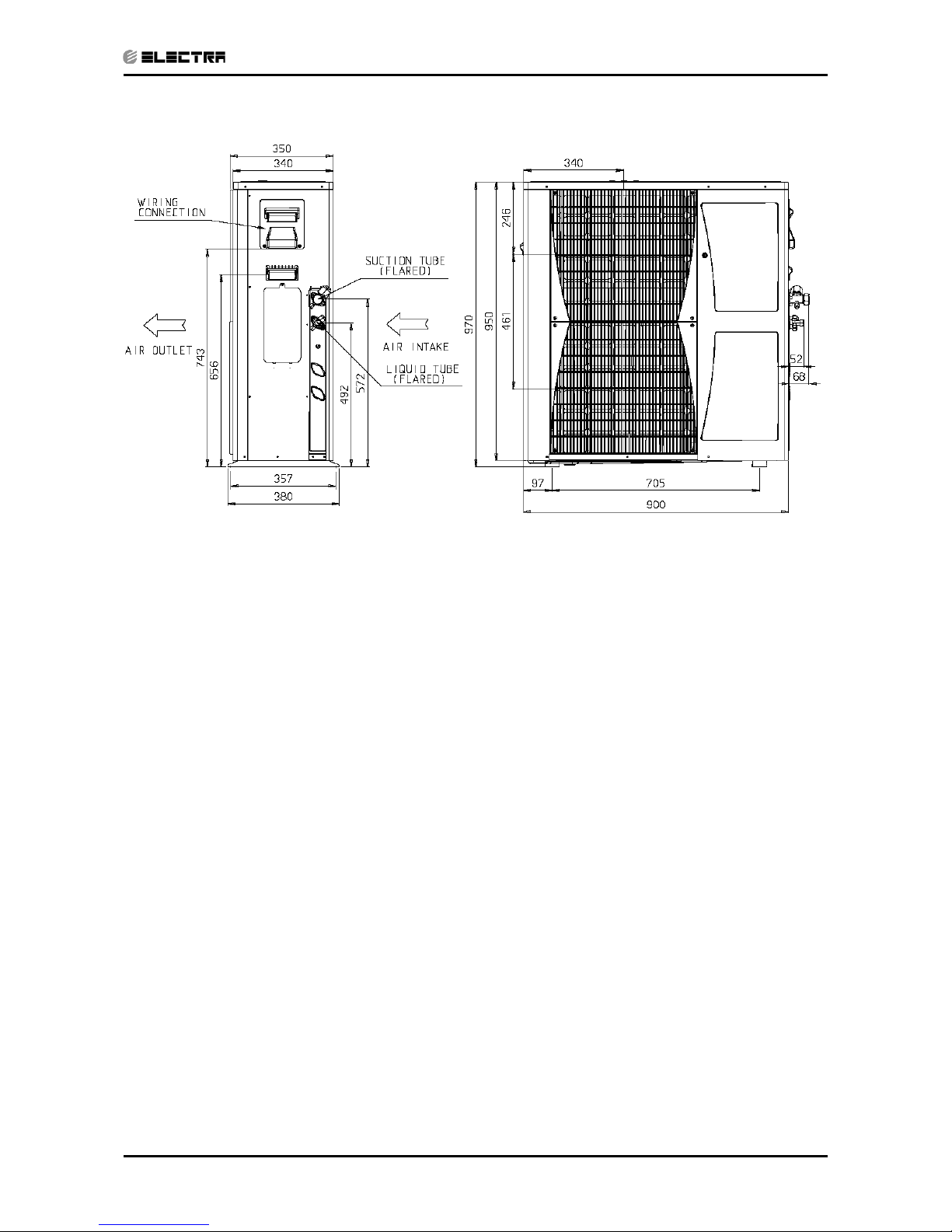
4.4 Outdoor Unit: OU10-36, OU10-47
Page 18
5-1
PERFORMANCE DATA & PRESSURE CURVES
Revision Y06-02Service Manual - KN Series
5. PERFORMANCE DATA
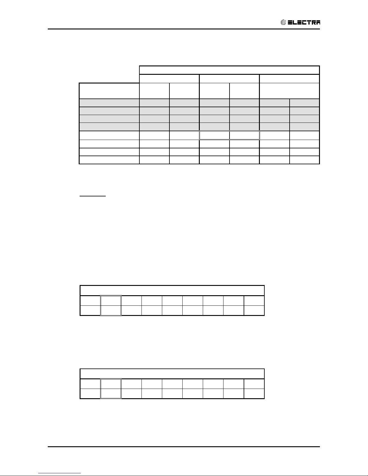
5.1 KN24 / OU7-24 R410A 1PH/3PH
5.1.1 Cooling Mode at 7.5m Tubing Connection.
230V : Indoor Fan at High Speed.
ENTERING AIR
DB OD COIL (°C)
DATA
ENTERING AIR WB/DB ID COIL ( °C)
15/21 17/24 19/27 21/29 23/32
15
(1)
TC
7.14 7.39 7.57 7.74 7.86
SC
4.80 5.00 5.20 5.33 5.43
PI
1.60 1.60 1.60 1.60 1.61
20
(1)
TC
6.90 7.28 7.51 7.68 7.85
SC
4.70 4.96 5.17 5.31 5.41
PI
1.73 1.74 1.74 1.75 1.76
25
TC
6.53 7.05 7.42 7.64 7.83
SC
4.58 4.86 5.13 5.28 5.37
PI
1.87 1.88 1.90 1.91 1.92
30
TC
6.11 6.65 7.19 7.44 7.66
SC
4.44 4.72 5.02 5.16 5.26
PI
2.02 2.05
2.07
2.08 2.10
35
TC
5.66 6.14
6.77
7.11 7.45
SC
4.22 4.52 4.90 5.04 5.14
PI
2.18 2.21
2.25
2.27 2.28
40
TC
5.14 5.60
6.11
6.68 7.02
SC
3.98 4.28 4.64 4.78 4.88
PI
2.35 2.39 2.43 2.46 2.48
46
TC
4.46 4.88 5.37 5.93 6.39
SC
3.66 3.93 4.23 4.37 4.47
PI
2.57 2.60 2.66 2.70 2.73
LEGEND
TC – Total Cooling Capacity, kW
SC – Sensible Capacity, kW
PI – Power Input, kW
WB – Wet Bulb Temp., (
o
C)
DB – Dry Bulb Temp., (oC)
ID – Indoor
OD – Outdoor
(1) Marked area is below standard operating limits. For operating in low ambient
conditions, refer to Optional Accessories (Chapter 15).
Page 19
5-2
PERFORMANCE DATA & PRESSURE CURVES
Revision Y06-02 Service Manual - KN Series
5.1.2 Heating Mode at 7.5m Tubing Connection.
230V : Indoor Fan at High Speed.
ENTERING AIR DB ID COIL ( °C)
15 20 25
ENTERING AIR
WB OU COIL ( °C)
TH PI TH PI TH PI
-10 4.09 1.86 3.93 1.99 3.78 6.34
-7 4.40 1.91 4.24 2.02 4.09 6.46
-2 4.67 1.93 4.52 2.05 4.36 6.58
2 5.69 2.03
5.45 2.16
5.22 6.94
6 7.29 2.18 7.08 2.33 6.83 7.52
10 7.93 2.30
7.72 2.46
7.50 7.99
15 8.57 2.40 8.35 2.59 8.14 8.35
20 9.03 2.47 8.81 2.68 8.57 8.78
* the above chart includes the weighted deicing infleuence.
LEGEND
TH – Total Heating Capacity, kW
PI – Power Input, kW
WB – Wet Bulb Temp., (
o
C)
DB – Dry Bulb Temp., (
o
C)
ID – Indoor
OU – Outdoor
5.2 Capacity Correction Factor Due to Tubing Length (One Way)
TOTAL TUBING LENGTH
4m
7.5m
10m 15m 20m 25m 30m 40m 50m
1.01
1
0.98 0.97 0.96 0.95 0.94 --- ---
* Minimum recommended tubing length between indoor and outdoor units is 4m.
5.2.1 Heating
TOTAL TUBING LENGTH
4m
7.5m
10m 15m 20m 25m 30m 40m 50m
1.02
1
0.99 0.99 0.98 0.97 0.97 --- ---
* Minimum recommended tubing length between indoor and outdoor units is 4m.
Page 20
5-3
PERFORMANCE DATA & PRESSURE CURVES
Revision Y06-02Service Manual - KN Series
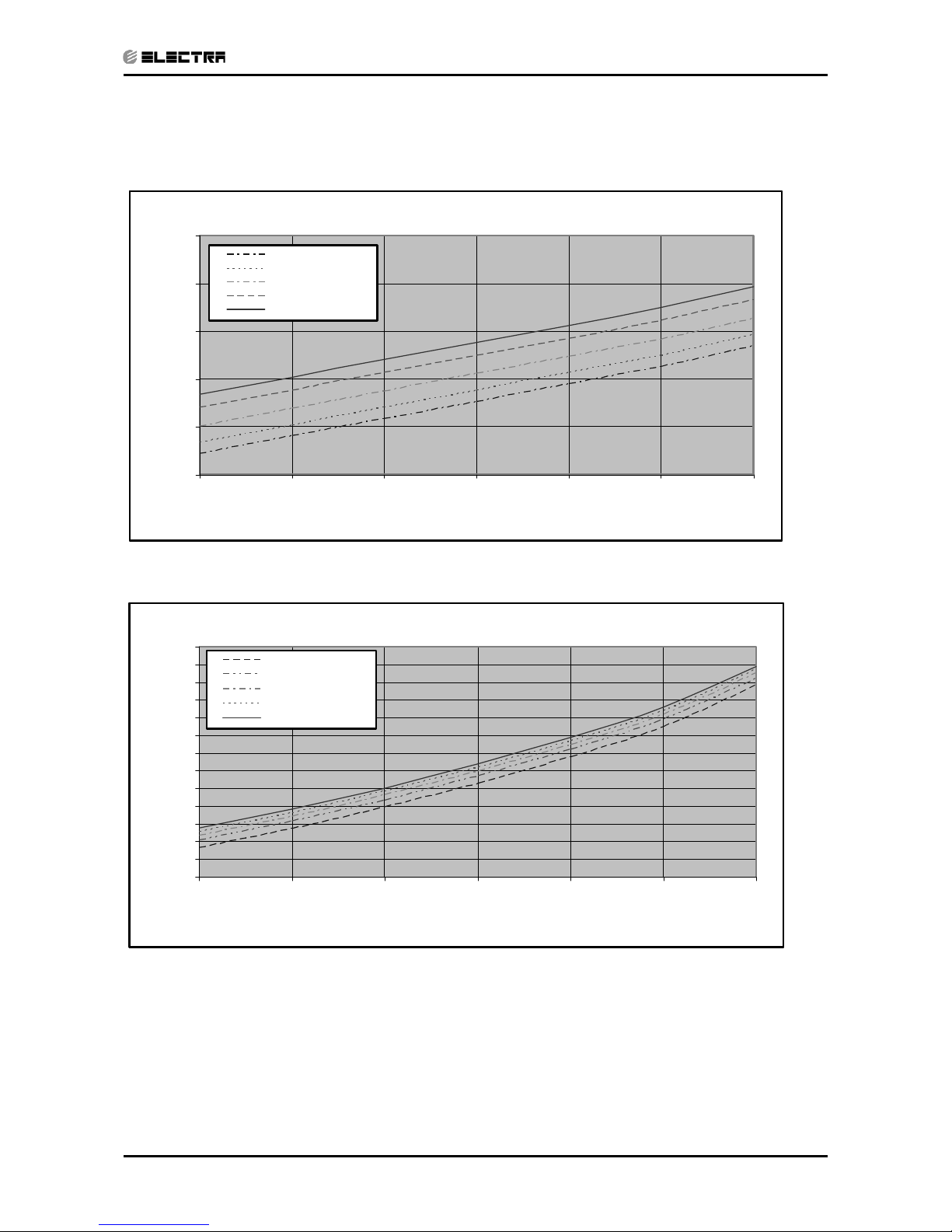
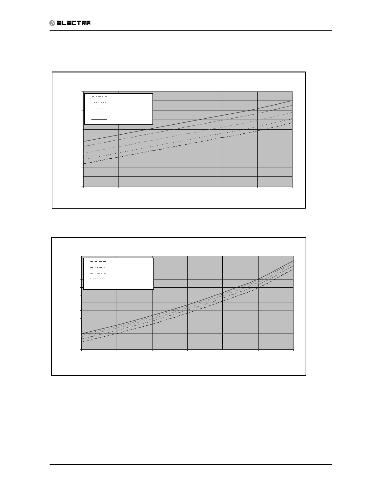
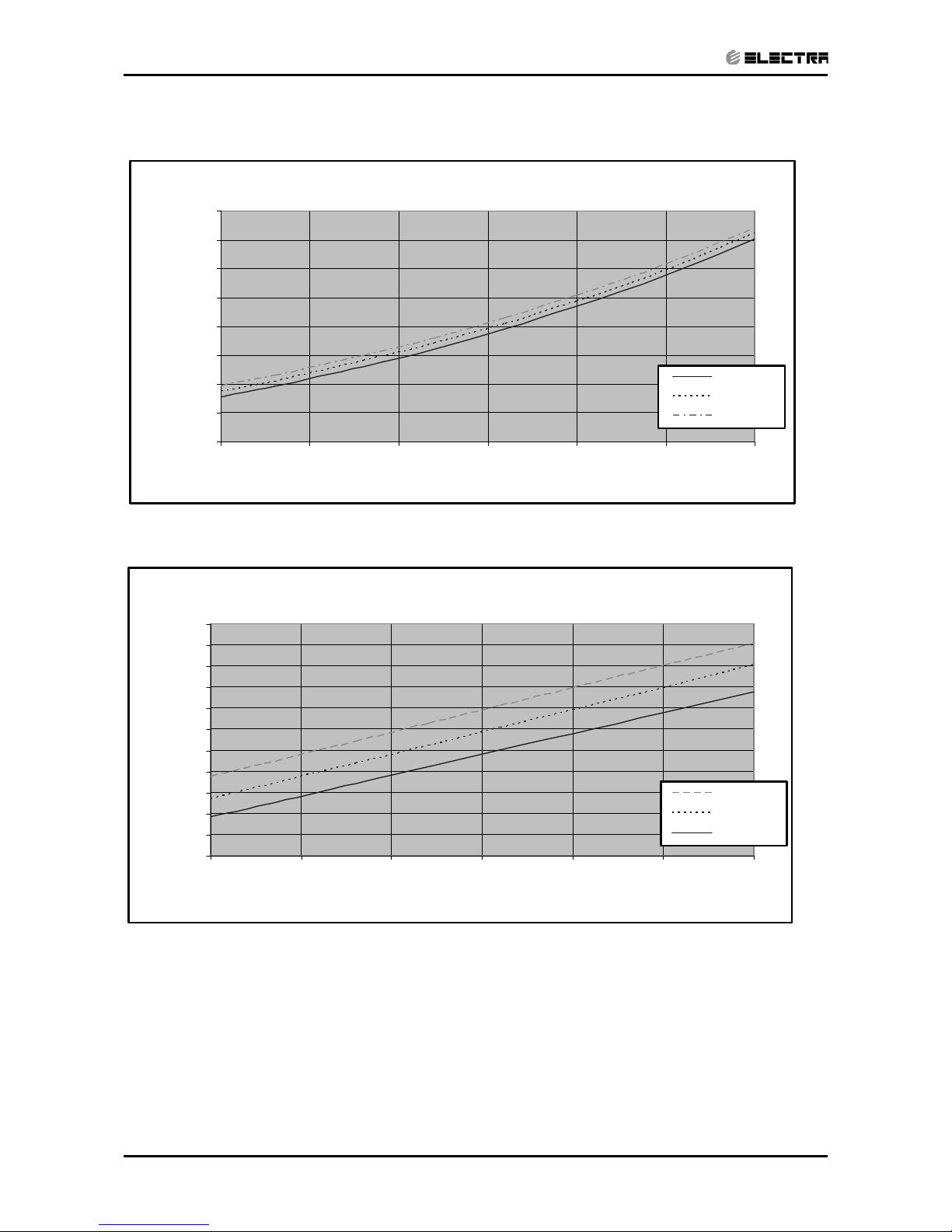
5.3 Pressure Curves.
5.3.1 Cooling.
Suction Pressure VS.Outdoor Temp
6
7
8
9
10
11
15 20 2530354046
Outdoor Temp.(DB oC )
Suction P ressure (Bar[g])
21/15(DB/W B ºC)
24/17(DB/W B ºC)
27/19(DB/W B ºC)
29/21(DB/WB ºC)
32/23(DB/W B ºC)
Discharge Pressure VS.Outdoor Temp
14
16
18
20
22
24
26
28
30
32
34
36
38
40
15 20 2530354046
Outdoor Temp.(DB oC )
Discharge Pressure (Bar[g])
21/15(DB/ W B º C)
24/17(DB/ W B º C)
27/19(DB/ W B º C)
29/21(DB/WB ºC)
32/23(DB/W B ºC)
Page 21
5-4
PERFORMANCE DATA & PRESSURE CURVES
Revision Y06-02 Service Manual - KN Series
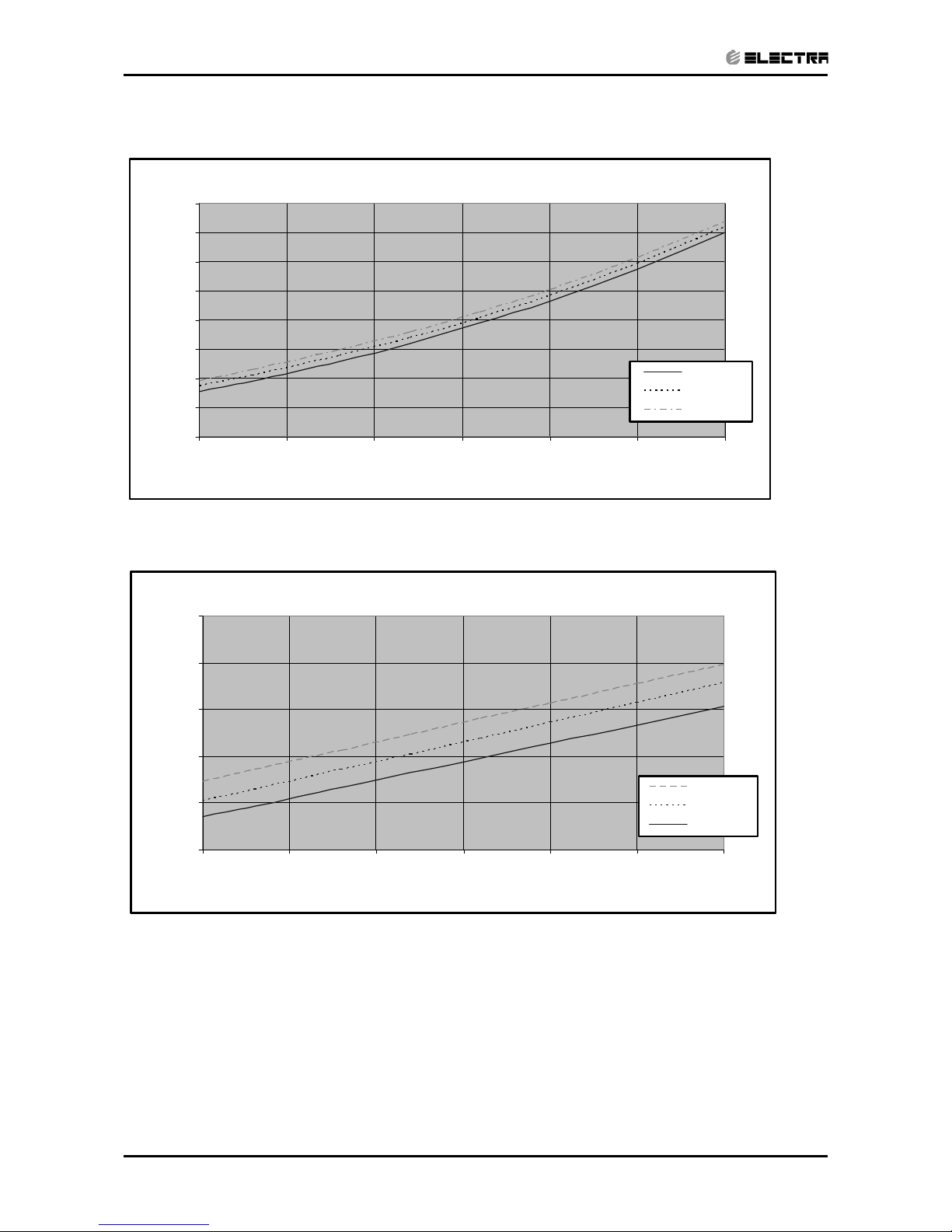
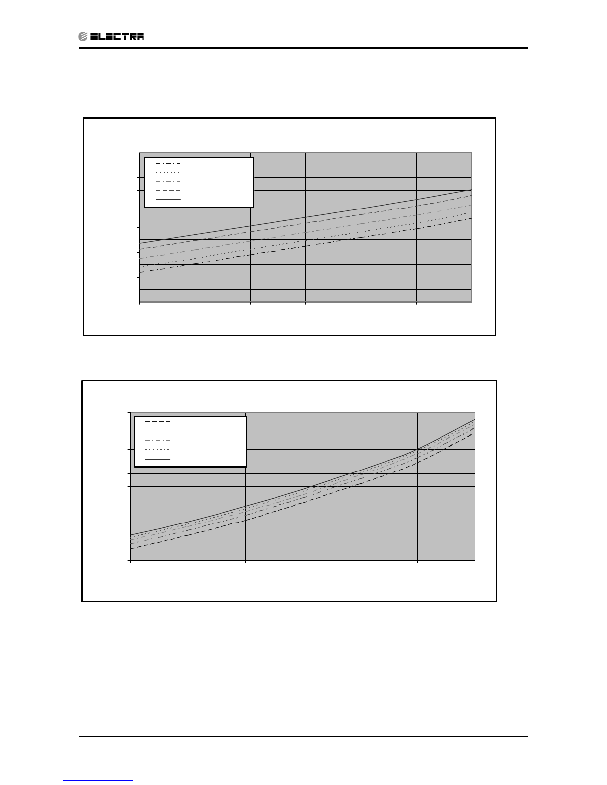
5.3.2 Heating.
Suction Pressure VS.Outdoor Temp
3
4
5
6
7
8
9
10
11
-10 -5 0 5 10 15 20
Outdoor Temp.( WB oC )
Sucti on Pressure(Bar[g])
15 DB (ºC)
20 DB (ºC)
25 DB (ºC)
Discharge Pressure VS.Outdoor Temp
18
23
28
33
38
43
-10 -5 0 5 10 15 20
Outdoor Temp.( WB oC )
Discharge Pressure(Bar[g])
25 DB (ºC)
20 DB (ºC)
15 DB (ºC)
Page 22

5-5
PERFORMANCE DATA & PRESSURE CURVES
Revision Y06-02Service Manual - KN Series
5.4 KN30 / OU8-30 R410A
5.4.1 Cooling Mode at 7.5m Tubing Connection.
230V : Indoor Fan at High Speed.
ENTERING AIR
DB OD COIL (°C)
DATA
ENTERING AIR WB/DB ID COIL ( °C)
15/21 17/24 19/27 21/29 23/32
15
(1)
TC
8.75 9.06 9.27 9.49 9.64
SC
5.88 6.13 6.37 6.53 6.65
PI
2.08 2.09 2.09 2.10 2.11
20
(1)
TC
8.46 8.92 9.20 9.42 9.62
SC
5.76 6.07 6.33 6.51 6.63
PI
2.26 2.27 2.28 2.29 2.29
25
TC
8.01 8.65 9.09 9.37 9.59
SC
5.61 5.95 6.28 6.46 6.58
PI
2.45 2.46 2.48 2.50 2.51
30
TC
7.49 8.15 8.81 9.12 9.39
SC
5.43 5.78 6.14 6.32 6.44
PI
2.64 2.68
2.70
2.72 2.75
35
TC
6.93 7.52
8.30
8.72 9.13
SC
5.17 5.54 6.00 6.17 6.29
PI
2.85 2.89
2.94
2.96 2.98
40
TC
6.31 6.86
7.49
8.19 8.61
SC
4.87 5.24 5.68 5.86 5.98
PI
3.07 3.12 3.17 3.21 3.24
46
TC
5.47 5.98 6.58 7.27 7.83
SC
4.49 4.81 5.18 5.36 5.48
PI
3.35 3.40 3.48 3.53 3.57
LEGEND
TC – Total Cooling Capacity, kW
SC – Sensible Capacity, kW
PI – Power Input, kW
WB – Wet Bulb Temp., (
o
C)
DB – Dry Bulb Temp., (oC)
ID – Indoor
OD – Outdoor
(1) Marked area is below standard operating limits. For operating in low ambient
conditions, refer to Optional Accessories (Chapter 15).
Page 23
5-6
PERFORMANCE DATA & PRESSURE CURVES
Revision Y06-02 Service Manual - KN Series
5.4.2 Heating Mode at 7.5m Tubing Connection.
230V : Indoor Fan at High Speed.
ENTERING AIR DB ID COIL ( °C)
15 20 25
ENTERING AIR
WB OU COIL ( °C)
TH PI TH PI TH PI
-10 5.16 2.30 4.97 2.45 4.77 2.58
-7 5.56 2.36 5.36 2.49 5.16 2.63
-2 5.90 2.39 5.70 2.53 5.51 2.68
2 7.18 2.51
6.88 2.66
6.59 2.82
6 9.21 2.69 8.94 2.88 8.63 3.06
10 10.01 2.84
9.74 3.04
9.48 3.25
15 10.82 2.97 10.55 3.20 10.28 3.40
20 11.40 3.05 11.13 3.31 10.82 3.57
* the above chart includes the weighted deicing infleuence.
LEGEND
TH – Total Heating Capacity, kW
PI – Power Input, kW
WB – Wet Bulb Temp., (
o
C)
DB – Dry Bulb Temp., (
o
C)
ID – Indoor
OU – Outdoor
5.5 Capacity Correction Factor Due to Tubing Length (One Way)
TOTAL TUBING LENGTH
4m
7.5m
10m 15m 20m 25m 30m 40m 50m
1.01
1
0.98 0.97 0.96 0.95 0.94 --- ---
* Minimum recommended tubing length between indoor and outdoor units is 4m.
5.5.1 Heating
TOTAL TUBING LENGTH
4m
7.5m
10m 15m 20m 25m 30m 40m 50m
1.02
1
0.99 0.99 0.98 0.97 0.97 --- ---
* Minimum recommended tubing length between indoor and outdoor units is 4m.
Page 24
5-7
PERFORMANCE DATA & PRESSURE CURVES
Revision Y06-02Service Manual - KN Series
5.6 KN30 / OU8-30T R410A
5.6.1 Cooling Mode at 7.5m Tubing Connection.
230V : Indoor Fan at High Speed.
ENTERING AIR
DB OD COIL (°C)
DATA
ENTERING AIR WB/DB ID COIL ( °C)
15/21 17/24 19/27 21/29 23/32
15
(1)
TC
8.75 9.06 9.27 9.49 9.64
SC
5.88 6.13 6.37 6.53 6.65
PI
2.03 2.03 2.04 2.04 2.05
20
(1)
TC
8.46 8.92 9.20 9.42 9.62
SC
5.76 6.07 6.33 6.51 6.63
PI
2.20 2.21 2.22 2.23 2.23
25
TC
8.01 8.65 9.09 9.37 9.59
SC
5.61 5.95 6.28 6.46 6.58
PI
2.38 2.40 2.41 2.43 2.44
30
TC
7.49 8.15 8.81 9.12 9.39
SC
5.43 5.78 6.14 6.32 6.44
PI
2.57 2.60
2.63
2.65 2.67
35
TC
6.93 7.52
8.30
8.72 9.13
SC
5.17 5.54 6.00 6.17 6.29
PI
2.77 2.81
2.86
2.88 2.90
40
TC
6.31 6.86
7.49
8.19 8.61
SC
4.87 5.24 5.68 5.86 5.98
PI
2.99 3.03 3.08 3.12 3.15
46
TC
5.47 5.98 6.58 7.27 7.83
SC
4.49 4.81 5.18 5.36 5.48
PI
3.26 3.31 3.39 3.43 3.47
LEGEND
TC – Total Cooling Capacity, kW
SC – Sensible Capacity, kW
PI – Power Input, kW
WB – Wet Bulb Temp., (
o
C)
DB – Dry Bulb Temp., (oC)
ID – Indoor
OD – Outdoor
(1) Marked area is below standard operating limits. For operating in low ambient
conditions, refer to Optional Accessories (Chapter 15).
Page 25
5-8
PERFORMANCE DATA & PRESSURE CURVES
Revision Y06-02 Service Manual - KN Series
5.6.2 Heating Mode at 7.5m Tubing Connection.
230V : Indoor Fan at High Speed.
ENTERING AIR DB ID COIL ( °C)
15 20 25
ENTERING AIR
WB OU COIL ( °C)
TH PI TH PI TH PI
-10 5.16 2.23 4.97 2.38 4.77 2.50
-7 5.56 2.29 5.36 2.41 5.16 2.54
-2 5.90 2.32 5.70 2.46 5.51 2.59
2 7.18 2.43
6.88 2.58
6.59 2.73
6 9.21 2.61 8.94 2.79 8.63 2.96
10 10.01 2.75
9.74 2.94
9.48 3.15
15 10.82 2.87 10.55 3.10 10.28 3.29
20 11.40 2.96 11.13 3.21 10.82 3.46
* the above chart includes the weighted deicing infleuence.
LEGEND
TH – Total Heating Capacity, kW
PI – Power Input, kW
WB – Wet Bulb Temp., (
o
C)
DB – Dry Bulb Temp., (oC)
ID – Indoor
OU – Outdoor
5.7 Capacity Correction Factor Due to Tubing Length (One Way)
TOTAL TUBING LENGTH
4m
7.5m
10m 15m 20m 25m 30m 40m 50m
1.01
1
0.98 0.97 0.96 0.95 0.94 ― ―
* Minimum recommended tubing length between indoor and outdoor units is 4m.
5.7.1 Heating
TOTAL TUBING LENGTH
4m
7.5m
10m 15m 20m 25m 30m 40m 50m
1.02
1
0.99 0.99 0.98 0.97 0.97 ― ―
* Minimum recommended tubing length between indoor and outdoor units is 4m.
Page 26
5-9
PERFORMANCE DATA & PRESSURE CURVES
Revision Y06-02Service Manual - KN Series
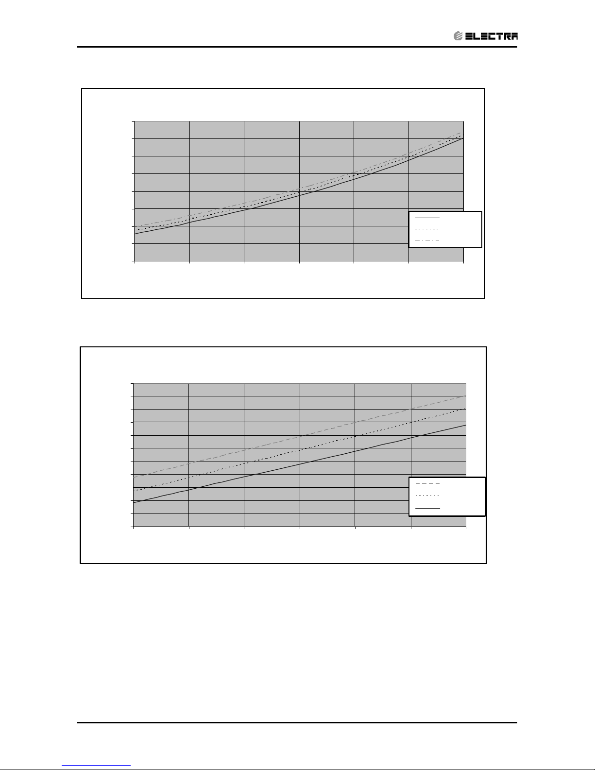
5.8 Pressure Curves.
5.8.1 KN30 / OU8-30 R410A - Cooling:
Suction Pressure VS.Outdoor Temp
5.0
5.5
6.0
6.5
7.0
7.5
8.0
8.5
9.0
9.5
10.0
15 20 2530354046
Outdoor Temp.(DB oC )
Suction Pressure (Bar[g])
21/15(DB/WB ºC)
24/17(DB/WB ºC)
27/19(DB/WB ºC)
29/21(DB/W B ºC)
32/23(DB/WB ºC)
Discharge Pressure VS.Outdoor Temp
16
18
20
22
24
26
28
30
32
34
36
38
40
15 20 2530354046
Outdoor Temp.(DB oC )
Discharge P ressure (Bar[g])
21/15(DB/WB ºC)
24/17(DB/WB ºC)
27/19(DB/WB ºC)
29/21(DB/W B ºC)
32/23(DB/WB ºC)
Page 27
5-10
PERFORMANCE DATA & PRESSURE CURVES
Revision Y06-02 Service Manual - KN Series
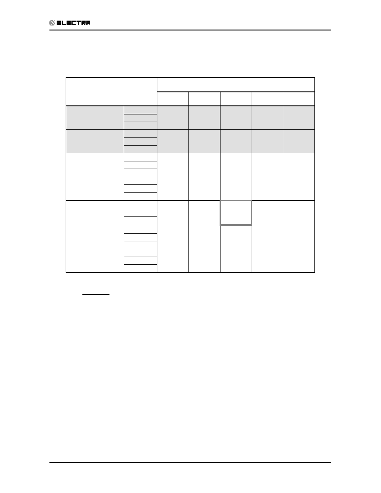
5.8.2 Heating.
Suction Pressure VS.Outdoor Temp
3.0
4.0
5.0
6.0
7.0
8.0
9.0
10.0
11.0
-10 -5 0 5 10 15 20
Outdoor Te mp.( WB oC )
Sucti on Pressure(Bar[g])
15 DB (ºC)
20 DB (ºC)
25 DB (ºC)
Discharge Pressure VS.Outdoor Temp
18
20
22
24
26
28
30
32
34
36
38
40
-10 -5 0 5 10 15 20
Outdoor Temp.( WB oC )
Discharge Pressure(Bar[g])
25 DB (ºC)
20 DB (ºC)
15 DB (ºC)
Page 28
5-11
PERFORMANCE DATA & PRESSURE CURVES
Revision Y06-02Service Manual - KN Series
5.9 Pressure Curves.
5.9.1 KN30 / OU8-30T R410A - Cooling:
Suction Pressure VS.Outdoor Temp
5.0
5.5
6.0
6.5
7.0
7.5
8.0
8.5
9.0
9.5
10.0
10.5
11.0
15 20 2530354046
Outdoor Temp.(DB oC )
Suction Pressure (Bar[g])
21/15(DB/WB ºC)
24/17(DB/WB ºC)
27/19(DB/WB ºC)
29/21(DB/WB ºC)
32/23(DB/W B ºC)
Discharge Pressure VS.Outdoor Temp
16
18
20
22
24
26
28
30
32
34
36
38
40
15 20 2530354046
Outdoor Temp.(DB oC )
Discharge Pressure (Bar[g])
21/15(DB/ WB º C)
24/17(DB/ W B ºC)
27/19(DB/ W B ºC)
29/21(DB/WB ºC)
32/23(DB/W B ºC)
Page 29
5-12
PERFORMANCE DATA & PRESSURE CURVES
Revision Y06-02 Service Manual - KN Series
5.8.2 Heating.
Suction Pressure VS.Outdoor Temp
3.0
4.0
5.0
6.0
7.0
8.0
9.0
10.0
11.0
-10 -5 0 5 10 15 20
Outdoor Temp.( WB oC )
Suction Pressure(Bar[g])
15 DB (ºC)
20 DB (ºC)
25 DB (ºC)
Discharge Pressure VS.Outdoor Temp
18
20
22
24
26
28
30
32
34
36
38
40
-10 -5 0 5 10 15 20
Outdoor Temp.( WB oC )
Discharge Pressure(Bar[g])
25 DB (ºC)
20 DB (ºC)
15 DB (ºC)
Page 30
5-13
PERFORMANCE DATA & PRESSURE CURVES
Revision Y06-02Service Manual - KN Series
5.9 KN36 / OU10-36 R410A
5.9.1 Cooling Mode at 7.5m Tubing Connection.
230V : Indoor Fan at High Speed.
ENTERING AIR
DB OD COIL (°C)
DATA
ENTERING AIR WB/DB ID COIL ( °C)
15/21 17/24 19/27 21/29 23/32
15
(1)
TC
10.65 11.03 11.29 11.55 11.73
SC
6.74 7.03 7.30 7.48 7.62
PI
2.47 2.47 2.48 2.48 2.50
20
(1)
TC
10.30 10.86 11.20 11.46 11.71
SC
6.60 6.96 7.26 7.46 7.60
PI
2.68 2.69 2.70 2.71 2.72
25
TC
9.74 10.52 11.06 11.40 11.67
SC
6.43 6.83 7.20 7.41 7.54
PI
2.89 2.91 2.93 2.95 2.97
30
TC
9.11 9.92 10.72 11.10 11.43
SC
6.23 6.62 7.04 7.25 7.39
PI
3.12 3.17
3.20
3.22 3.25
35
TC
8.44 9.16
10.10
10.61 11.11
SC
5.93 6.35 6.88 7.08 7.22
PI
3.37 3.42
3.48
3.51 3.53
40
TC
7.67 8.35
9.11
9.97 10.48
SC
5.59 6.01 6.51 6.71 6.85
PI
3.63 3.69 3.75 3.80 3.84
46
TC
6.66 7.28 8.00 8.84 9.53
SC
5.14 5.51 5.93 6.14 6.28
PI
3.97 4.03 4.12 4.18 4.23
LEGEND
TC – Total Cooling Capacity, kW
SC – Sensible Capacity, kW
PI – Power Input, kW
WB – Wet Bulb Temp., (
o
C)
DB – Dry Bulb Temp., (oC)
ID – Indoor
OD – Outdoor
(1) Marked area is below standard operating limits. For operating in low ambient
conditions, refer to Optional Accessories (Chapter 15).
Page 31

5-14
PERFORMANCE DATA & PRESSURE CURVES
Revision Y06-02 Service Manual - KN Series
5.9.2 Heating Mode at 7.5m Tubing Connection.
230V : Indoor Fan at High Speed.
ENTERING AIR DB ID COIL ( °C)
15 20 25
ENTERING AIR
WB OU COIL ( °C)
TH PI TH PI TH PI
-10 5.30 2.88 5.10 3.07 4.90 3.22
-7 5.71 2.95 5.50 3.11 5.30 3.28
-2 6.06 2.99 5.86 3.17 5.66 3.35
2 7.37 3.13
7.07 3.33
6.77 3.53
6 10.40 3.37 10.10 3.60 9.75 3.82
10 11.31 3.55
11.01 3.80
10.71 4.06
15 12.22 3.71 11.92 4.00 11.62 4.25
20 12.88 3.82 12.57 4.14 12.22 4.46
* the above chart includes the weighted deicing infleuence.
LEGEND
TH – Total Heating Capacity, kW
PI – Power Input, kW
WB – Wet Bulb Temp., (
o
C)
DB – Dry Bulb Temp., (
o
C)
ID – Indoor
OU – Outdoor
5.10 Capacity Correction Factor Due to Tubing Length (One Way)
TOTAL TUBING LENGTH
4m
7.5m
10m 15m 20m 25m 30m 40m 50m
1.01
1
0.98 0.97 0.96 0.95 0.94 0.93 0.90
* Minimum recommended tubing length between indoor and outdoor units is 4m.
5.10.1 Heating
TOTAL TUBING LENGTH
4m
7.5m
10m 15m 20m 25m 30m 40m 50m
1.02
1
0.99 0.99 0.98 0.97 0.97 0.96 0.95
* Minimum recommended tubing length between indoor and outdoor units is 4m.
Page 32

5-15
PERFORMANCE DATA & PRESSURE CURVES
Revision Y06-02Service Manual - KN Series
5.11 Pressure Curves.
5.11.1 Cooling:
Discharge Pressure VS.Outdoor Temp
10
12
14
16
18
20
22
24
26
28
30
32
34
36
38
40
15 20 25 30 35 40 46
Outdoor Temp.(DB oC )
Discharge Pressure (Bar[g])
15/21(WB/DB ºC)
17/24(WB/DB ºC)
19/27(WB/DB ºC)
21/29(WB/DB ºC)
23/32(WB/DB ºC)
Suction Pressure VS.Outdoor Temp
4.0
5.0
6.0
7.0
8.0
9.0
10.0
11.0
15 20 25 30 35 40 46
Outdoor Temp.(DB oC )
Suction Pressure (Bar[g])
15/21(WB/DB ºC)
17/24(WB/DB ºC)
19/27(WB/DB ºC)
21/29(WB/DB ºC)
23/32(WB/DB ºC)
Page 33

5-16
PERFORMANCE DATA & PRESSURE CURVES
Revision Y06-02 Service Manual - KN Series
5.11.2 Heating
Discharge Pressure VS.Outdoor Temp
16
18
20
22
24
26
28
30
32
34
36
38
-10 -5 0 5 10 15 20
Outdoor Temp.( WB oC )
Discharge Pressure(Bar[g])
25 DB (ºC)
20 DB (ºC)
15 DB (ºC)
Suction Pressure VS.Outdoor Temp
3.0
4.0
5.0
6.0
7.0
8.0
9.0
10.0
-10 -5 0 5 10 15 20
Outdoor Temp.( WB oC )
Suction Pressure(Bar[g])
15 DB (ºC)
20 DB (ºC)
25 DB (ºC)
Page 34

5-17
PERFORMANCE DATA & PRESSURE CURVES
Revision Y06-02Service Manual - KN Series
5.12 KN36 / OU10-36T R410A
5.12.1 Cooling Mode at 7.5m Tubing Connection.
230V : Indoor Fan at High Speed.
ENTERING AIR
DB OD COIL (°C)
DATA
ENTERING AIR WB/DB ID COIL ( °C)
15/21 17/24 19/27 21/29 23/32
15
(1)
TC
10.22 10.59 10.84 11.10 11.26
SC
6.35 6.62 6.88 7.05 7.18
PI
2.37 2.37 2.38 2.38 2.40
20
(1)
TC
9.89 10.43 10.76 11.01 11.25
SC
6.22 6.56 6.83 7.03 7.16
PI
2.57 2.58 2.59 2.60 2.61
25
TC
9.36 10.10 10.62 10.95 11.21
SC
6.06 6.43 6.78 6.98 7.11
PI
2.78 2.80 2.82 2.83 2.85
30
TC
8.75 9.53 10.29 10.66 10.98
SC
5.87 6.24 6.63 6.83 6.96
PI
3.00 3.04
3.07
3.09 3.12
35
TC
8.10 8.79
9.70
10.19 10.67
SC
5.58 5.98 6.48 6.67 6.80
PI
3.23 3.29
3.34
3.37 3.38
40
TC
7.37 8.02
8.75
9.57 10.06
SC
5.26 5.66 6.13 6.32 6.45
PI
3.49 3.54 3.60 3.65 3.68
46
TC
6.39 6.99 7.69 8.49 9.15
SC
4.85 5.19 5.59 5.78 5.91
PI
3.81 3.87 3.96 4.01 4.06
LEGEND
TC – Total Cooling Capacity, kW
SC – Sensible Capacity, kW
PI – Power Input, kW
WB – Wet Bulb Temp., (
o
C)
DB – Dry Bulb Temp., (oC)
ID – Indoor
OD – Outdoor
(1) Marked area is below standard operating limits. For operating in low ambient
conditions, refer to Optional Accessories (Chapter 15).
Page 35

5-18
PERFORMANCE DATA & PRESSURE CURVES
Revision Y06-02 Service Manual - KN Series
5.12.2 Heating Mode at 7.5m Tubing Connection.
230V : Indoor Fan at High Speed.
ENTERING AIR DB ID COIL ( °C)
15 20 25
ENTERING AIR
WB OU COIL ( °C)
TH PI TH PI TH PI
-10 5.41 2.94 5.20 3.14 5.00 3.29
-7 5.82 3.02 5.61 3.18 5.41 3.36
-2 6.18 3.05 5.97 3.24 5.77 3.42
2 7.52 3.20
7.21 3.40
6.90 3.61
6 10.61 3.44 10.30 3.68 9.94 3.91
10 11.54 3.63
11.23 3.88
10.92 4.15
15 12.46 3.79 12.15 4.08 11.85 4.34
20 13.13 3.90 12.82 4.23 12.46 4.56
* the above chart includes the weighted deicing infleuence.
LEGEND
TH – Total Heating Capacity, kW
PI – Power Input, kW
WB – Wet Bulb Temp., (
o
C)
DB – Dry Bulb Temp., (
o
C)
ID – Indoor
OU – Outdoor
5.13 Capacity Correction Factor Due to Tubing Length (One Way)
TOTAL TUBING LENGTH
4m
7.5m
10m 15m 20m 25m 30m 40m 50m
1.01
1
0.98 0.97 0.96 0.95 0.94 0.93 0.90
* Minimum recommended tubing length between indoor and outdoor units is 4m.
5.13.1 Heating
TOTAL TUBING LENGTH
4m
7.5m
10m 15m 20m 25m 30m 40m 50m
1.02
1
0.99 0.99 0.98 0.97 0.97 0.96 0.95
* Minimum recommended tubing length between indoor and outdoor units is 4m.
Page 36

5-19
PERFORMANCE DATA & PRESSURE CURVES
Revision Y06-02Service Manual - KN Series
5.14 Pressure Curves.
5.14.1 Cooling:
Discharge Pressure VS.Outdoor Temp
10
12
14
16
18
20
22
24
26
28
30
32
34
36
38
40
15 20 25 30 35 40 46
Outdoor Temp.(DB oC )
Discharge Pressure (Bar[g])
15/21(WB/DB ºC)
17/24(WB/DB ºC)
19/27(WB/DB ºC)
21/29(WB/DB ºC)
23/32(WB/DB ºC)
Suction Pressure VS.Outdoor Temp
4.0
5.0
6.0
7.0
8.0
9.0
10.0
11.0
15 20 25 30 35 40 46
Outdoor Temp.(DB oC )
Suction Pressure (Bar[g])
15/21(WB/DB ºC)
17/24(WB/DB ºC)
19/27(WB/DB ºC)
21/29(WB/DB ºC)
23/32(WB/DB ºC)
Page 37

5-20
PERFORMANCE DATA & PRESSURE CURVES
Revision Y06-02 Service Manual - KN Series
5.14.2 Heating:
Discharge Pressure VS.Outdoor Temp
16
18
20
22
24
26
28
30
32
34
36
38
40
42
-10 -5 0 5 10 15 20
Outdoor Temp.( WB oC )
Discharge Pressure(Bar[g])
25 DB (ºC)
20 DB (ºC)
15 DB (ºC)
Suction Pressure VS.Outdoor Temp
3.0
4.0
5.0
6.0
7.0
8.0
9.0
10.0
-10 -5 0 5 10 15 20
Outdoor Temp.( WB oC )
Suction Pressure(Bar[g])
15 DB (ºC)
20 DB (ºC)
25 DB (ºC)
Page 38

5-21
PERFORMANCE DATA & PRESSURE CURVES
Revision Y06-02Service Manual - KN Series
5.15 KN45 / OU10-47T R410A
5.15.1 Cooling Mode at 7.5m Tubing Connection.
230V : Indoor Fan at High Speed.
ENTERING AIR
DB OD COIL (°C)
DATA
ENTERING AIR WB/DB ID COIL ( °C)
15/21 17/24 19/27 21/29 23/32
15
(1)
TC
13.02 13.48 13.80 14.13 14.34
SC
8.17 8.52 8.85 9.07 9.24
PI
3.12 3.13 3.13 3.14 3.16
20
(1)
TC
12.59 13.27 13.69 14.02 14.32
SC
8.00 8.44 8.80 9.05 9.21
PI
3.39 3.40 3.41 3.43 3.43
25
TC
11.92 12.87 13.53 13.94 14.28
SC
7.80 8.28 8.73 8.98 9.15
PI
3.66 3.69 3.71 3.73 3.76
30
TC
11.14 12.13 13.11 13.57 13.98
SC
7.55 8.03 8.54 8.79 8.95
PI
3.95 4.01
4.04
4.07 4.11
35
TC
10.32 11.20
12.35
12.97 13.58
SC
7.18 7.70 8.34 8.58 8.75
PI
4.26 4.33
4.40
4.43 4.46
40
TC
9.38 10.21
11.14
12.19 12.81
SC
6.77 7.29 7.89 8.14 8.31
PI
4.59 4.66 4.74 4.80 4.85
46
TC
8.14 8.90 9.79 10.81 11.65
SC
6.24 6.68 7.19 7.44 7.61
PI
5.02 5.09 5.21 5.28 5.34
LEGEND
TC – Total Cooling Capacity, kW
SC – Sensible Capacity, kW
PI – Power Input, kW
WB – Wet Bulb Temp., (
o
C)
DB – Dry Bulb Temp., (oC)
ID – Indoor
OD – Outdoor
(1) Marked area is below standard operating limits. For operating in low ambient
conditions, refer to Optional Accessories (Chapter 15).
Page 39

5-22
PERFORMANCE DATA & PRESSURE CURVES
Revision Y06-02 Service Manual - KN Series
5.15.2 Heating Mode at 7.5m Tubing Connection.
230V : Indoor Fan at High Speed.
ENTERING AIR DB ID COIL ( °C)
15 20 25
ENTERING AIR
WB OU COIL ( °C)
TH PI TH PI TH PI
-10 6.93 3.70 6.67 3.94 6.40 4.14
-7 7.46 3.80 7.19 4.00 6.93 4.22
-2 7.92 3.84 7.66 4.07 7.39 4.31
2 9.64 4.03
9.24 4.28
8.84 4.54
6 13.60 4.33 13.20 4.63 12.74 4.92
10 14.78 4.57
14.39 4.88
13.99 5.22
15 15.97 4.77 15.58 5.14 15.18 5.46
20 16.83 4.91 16.43 5.32 15.97 5.74
* the above chart includes the weighted deicing infleuence.
LEGEND
TH – Total Heating Capacity, kW
PI – Power Input, kW
WB – Wet Bulb Temp., (
o
C)
DB – Dry Bulb Temp., (
o
C)
ID – Indoor
OU – Outdoor
5.16 Capacity Correction Factor Due to Tubing Length (One Way)
TOTAL TUBING LENGTH
4m
7.5m
10m 15m 20m 25m 30m 40m 50m
1.01
1
0.98 0.97 0.96 0.95 0.94 0.93 0.90
* Minimum recommended tubing length between indoor and outdoor units is 4m.
5.16.1 Heating
TOTAL TUBING LENGTH
4m
7.5m
10m 15m 20m 25m 30m 40m 50m
1.02
1
0.99 0.99 0.98 0.97 0.97 0.96 0.95
* Minimum recommended tubing length between indoor and outdoor units is 4m.
Page 40

5-23
PERFORMANCE DATA & PRESSURE CURVES
Revision Y06-02Service Manual - KN Series
5.17 Pressure Curves.
Cooling:
Discharge Pressure VS.Outdoor Temp
10
12
14
16
18
20
22
24
26
28
30
32
34
36
38
40
15 20 25 30 35 40 46
Outdoor Temp.(DB oC )
Discharge Pressure (Bar[g])
15/21(WB/DB ºC)
17/24(WB/DB ºC)
19/27(WB/DB ºC)
21/29(WB/DB ºC)
23/32(WB/DB ºC)
Suction Pressure VS.Outdoor Temp
4.0
5.0
6.0
7.0
8.0
9.0
10.0
11.0
15 20 25 30 35 40 46
Outdoor Temp.(DB oC )
Suction Pressure (Bar[g])
15/21(WB/DB ºC)
17/24(WB/DB ºC)
19/27(WB/DB ºC)
21/29(WB/DB ºC)
23/32(WB/DB ºC)
Page 41

5-24
PERFORMANCE DATA & PRESSURE CURVES
Revision Y06-02 Service Manual - KN Series
5.17.2 Heating
Discharge Pressure VS.Outdoor Temp
16
18
20
22
24
26
28
30
32
34
36
38
40
-10 -5 0 5 10 15 20
Outdoor Temp.( WB oC )
Discharge Pressure(Bar[g])
25 DB (ºC)
20 DB (ºC)
15 DB (ºC)
Suction Pressure VS.Outdoor Temp
3.0
4.0
5.0
6.0
7.0
8.0
9.0
10.0
11.0
-10 -5 0 5 10 15 20
Outdoor Temp.( WB oC )
Suction Pressure(Bar[g])
15 DB (ºC)
20 DB (ºC)
25 DB (ºC)
Page 42

6-1
ELECTRICAL DATA
Revision Y06-02Service Manual - KN Series
6. ELECTRICAL DATA
6.1 Single Phase Units
MODEL KN 24 KN 30
Power Supply
To Outdoor To Outdoor
1PH – 230V – 50 Hz 1PH – 230V – 50 Hz
Max Current, A 15 17
Circuit Breaker 20 25
Power Supply Wiring No. X
Cross Section mm
2
3 X 2.5 mm
2
3 X 4 mm
2
Interconnecting Cable RC
Model No. X Cross Section mm
2
6X1.5 mm2 + 2 X 0.5 mm2 (OCT Sensor) 6 X 1.5 mm2 + 2 X 0.5 mm2 (OCT Sensor)
Interconnecting Cable ST
Model No. X Cross Section mm
2
5X1.5 mm2 + 2 X 0.5 mm2 (OCT Sensor) 5 X 1.5 mm2 + 2 X 0.5 mm2 (OCT Sensor)
MODEL KN 36
Power Supply
To Outdoor
1PH – 230V – 50 Hz
Max Current, A 22.4
Circuit Breaker 25
Power Supply Wiring No. X
Cross Section mm
2
3 X 4 mm
2
Interconnecting Cable RC
Model No. X Cross Section mm
2
6 X 1.5 mm2 + 2 X 0.5 mm2 (OCT Sensor)
Interconnecting Cable ST
Model No. X Cross Section mm
2
5 X 1.5 mm2 + 2 X 0.5 mm2 (OCT Sensor)
6.2 Single Phase Units + Optional Heating Element
MODEL KN 24 KN30
Power Supply
To Outdoor To Outdoor
1PH – 230V – 50 Hz 1PH – 230V – 50 Hz
Heating Element, kW 2.1 2.7
Max Current, A 25.5 28
Circuit Breaker 32 32
Power Supply Wiring
No. X Cross Section mm
2
3 X 4 mm
2
3 X 4 mm
2
Interconnecting Cable RC
Model No. X Cross Section
mm
2
6 X 2.5 mm2 + 2 X 0.5 mm2 (OCT Sensor) 6 X 2.5 mm2 + 2 X 0.5 mm2 (OCT Sensor
Interconnecting Cable ST
Model No. X Cross Section
mm
2
5 X 2.5 mm2 + 2 X 0.5 mm2 (OCT Sensor)
5 X 2.5 mm
2
+ 2 X 0.5 mm2 (OCT
Sensor)
6.3 Three Phase Units
MODEL KN 24T KN30T
Power Supply
To Outdoor To Outdoor
3PH – 400V – 50 Hz 3PH – 400V – 50 Hz
Max Current, A 3 x 7.5 3 x 9.2
Circuit Breaker 3 x 10 3 x 16
Power Supply Wiring
No. X Cross Section mm
2
5 X 1.5 mm
2
5 X 1.5 mm
2
Interconnecting Cable RC
Model No. X Cross Section
mm
2
6 X 1.5 mm2 + 2 X 0.5 mm2 (OCT Sensor) 6 X 1.5 mm2 + 2 X 0.5 mm2 (OCT Sensor)
Interconnecting Cable ST
Model No. X Cross Section
mm
2
5 X 1.5 mm2 + 2 X 0.5 mm2 (OCT Sensor) 5 X 1.5 mm2 + 2 X 0.5 mm2 (OCT Sensor)
Page 43

6-2
ELECTRICAL DATA
Revision Y06-02 Service Manual - KN Series
MODEL KN 36T KN 45T
Power Supply
To Outdoor To Outdoor
3PH – 400V – 50 Hz 3PH – 400V – 50 Hz
Max Current, A 3 x 11.9 3 x 17.5
Circuit Breaker 3 x 16 3 x 20
Power Supply Wiring
No. X Cross Section mm
2
5 X 2.5 mm
2
5 X 2.5 mm
2
Interconnecting Cable RC
Model No. X Cross Section
mm
2
6 X 1.5 mm2 + 2 X 0.5 mm2 (OCT Sensor) 6 X 1.5 mm2 + 2 X 0.5 mm2 (OCT Sensor)
Interconnecting Cable ST
Model No. X Cross Section
mm
2
5 X 2.5 mm2 + 2 X 0.5 mm2 (OCT Sensor) 5 X 1.5 mm2 + 2 X 0.5 mm2 (OCT Sensor)
6.4 Three Phase Units + Optional Heating Element
MODEL KN 24T KN 30T
Power Supply
To Outdoor To Outdoor
3PH – 400V – 50 Hz 3PH – 400V – 50 Hz
Heating Element, kW 2.1 2.7
Max Current, A 3 X 10.1 3 X 14.6
Circuit Breaker 3 X 16 3 X 16
Power Supply Wiring
No. X Cross Section mm
2
5 X 1.5 mm
2
5 X 2.5 mm
2
Interconnecting Cable RC
Model No. X Cross Section mm
2
6 X 1.5 mm2 + 2 X 0.5 mm2 (OCT Sensor) 6 X 1.5 mm2 + 2 X 0.5 mm2 (OCT Sensor
Interconnecting Cable ST
Model No. X Cross Section mm
2
5 X 1.5 mm2 + 2 X 0.5 mm2 (OCT Sensor) 5 X 1.5 mm2 + 2 X 0.5 mm2 (OCT Sensor)
MODEL KN 36T KN 45T
Power Supply
To Outdoor To Outdoor
3PH – 400V – 50 Hz 3PH – 400V – 50 Hz
Heating Element, kW 3.0 3.0
Max Current, A 3 X 16.2 3 X 21.9
Circuit Breaker 3 X 20 3 X 25
Power Supply Wiring
No. X Cross Section mm
2
5 X 2.5 mm
2
5 X 2.5 mm
2
Interconnecting Cable RC
Model No. X Cross Section mm
2
8 X 1.5 mm2 + 2 X 0.5 mm2 (OCT Sensor) 8 X 1.5 mm2 + 2 X 0.5 mm2 (OCT Sensor
Interconnecting Cable ST
Model No. X Cross Section mm
2
7 X 1.5 mm2 + 2 X 0.5 mm2 (OCT Sensor) 7 X 1.5 mm2 + 2 X 0.5 mm2 (OCT Sensor)
(1) The power supply to the heating element kit is provided separately from the main power supply unit.
NOTE
Power wiring cord should comply with local lows and electrical regulations requirements.
Page 44

7-1
WIRING DIAGRAMS
Revision Y06-02Service Manual - KN Series
7. WIRING DIAGRAMS
7.1 Indoor Unit: KN 24/30 (Power Supply to Outdoor)
7.2 Indoor Unit: KN 24 /30 (Power Supply to Outdoor 3PH)
ICT
SENSOR
CAP1
2
XT2
1
RELAY
BN
BK
5
34 6
XT1
C1 ACB
BK
BN
RD
RD
BK
RD
RD
SWING
MOTOR
RD
BU
N
GNY E
DISPLAY
BOARD
P3
FAN1
ROOM
SENSOR
OUT
P5 P10
GULP
PUMP
P8P9 P12
P14
P11
P4
P6
P1
P2
FUSE
FUSE
HCTIWS CTP
Water switch
RELAY
PTC
PTC
PLUG
PLUG
PLUG
NIP21
PTC
CHOICE NOTES:
Please ignored broken
line for ST model
LEGEND:
B K - B L A C K
B U - B L U E
BN - BROWN
OG - ORANGE
R D - R E D
W H - W H I T E
Y E - Y E L L O W
FU - F U S E
M S - M O T O R S W I N G
GNYE - YELLOW GREEN
VOLTAGE:
220-240V
« 50HZ
SWING
MOTOR
CAP1
2
XT2
1
BK
BN
34 56
XT1
C1 C
BA
BNRDBK
WH
BU
RD
GNYE
BU
N
GNY E
P3
FAN1
DISPLAY
BOARD
P11
P1
P2
ICT
SENSOR
P10OUT
P5
P14
P9 P12 P8
ROOM
SENSOR
GULP
RD
BU
PUMP
P6
P4
PTC
PTC
PTC
NIP21
Water switch
CN406CN405
FUSE
CN403
CN402
CN402A
CN403A
BU
WH
PLUG
FUSE
CN401
CN401A
RD
VOLTAGE:
380V 3N-50HZ
CHOICE NOTES:
Please ignored broken
line for ST model
LEGEND:
B K - B L A C K
B U - B L U E
BN - BROWN
OG - ORANGE
R D - R E D
W H - W H I T E
Y E - Y E L L O W
FU - F U S E
M S - M O T O R S W I N G
GNYE - YELLOW GREEN
Page 45

7-2
WIRING DIAGRAMS
Revision Y06-02 Service Manual - KN Series
7.3 Outdoor Unit: OU7-24 / 30 1PH
7.4 Outdoor Unit: OU7-24 / 30 3PH
Page 46

7-3
WIRING DIAGRAMS
Revision Y06-02Service Manual - KN Series
7.5 Indoor Unit: KN 36 / 36T / 45T
7.6 Outdoor Unit: OU10-36
Page 47

7-4
WIRING DIAGRAMS
Revision Y06-02 Service Manual - KN Series
7.7 Outdoor Unit: OU10-36T
7.8 Outdoor Unit: OU10-47T
Page 48

8-1
ELECTRICAL CONNECTIONS
Revision Y06-02Service Manual - KN Series
8. ELECTRICAL CONNECTIONS
8.1 KN 24/30/36/45 (Power Supply to Outdoor)
8.2 KN 24/30/36/45 3PH
Page 49

9-1
REFRIGERATION DIAGRAMS
Revision Y06-02Service Manual - KN Series
9. REFRIGERATION DIAGRAMS
9.1 Heat Pump Models
9.1.1 KN 24 R410A
Page 50

9-2
REFRIGERATION DIAGRAMS
Revision Y06-02 Service Manual - KN Series
9.1.2 KN 30 R410A
Page 51

9-3
REFRIGERATION DIAGRAMS
Revision Y06-02Service Manual - KN Series
9.1.3 KN 36 R410A
Page 52

9-4
REFRIGERATION DIAGRAMS
Revision Y06-02 Service Manual - KN Series
9.1.4 KN 36T R410A
Page 53

9-5
REFRIGERATION DIAGRAMS
Revision Y06-02Service Manual - KN Series
9.1.5 KN 45T R410A
Page 54

9-6
REFRIGERATION DIAGRAMS
Revision Y06-02 Service Manual - KN Series
9.2 Cooling Only Models
9.2.1 KN 24 / 30 / 36 / 45 R410A
Page 55

10-1
TUBING CONNECTIONS
Revision Y06-02Service Manual - KN Series
10. TUBING CONNECTIONS
TUBE (Inch)
TORQUE (Nm)
¼” ⅜” ½” ⅝” ¾”
Flare Nuts 11-13 40-45 60-65 70-75 80-85
Valve Cap 13-20 13-20 18-25 18-25 40-50
Service Port Cap 11-13 11-13 11-13 11-13 11-13
1. Valve Protection Cap-end
2. Refrigerant Valve Port (use Allen wrench to open/close)
3. Valve Protection Cap
4. Refrigerant Valve
5. Service Port Cap
6. Flare Nut
7. Unit Back Side
8. Copper Tube
When the outdoor unit is installed above the indoor unit an oil trap is required every 5m along
the suction line at the lowest point of the riser. Incase the indoor unit is installed above the
outdoor, no trap is required.
Page 56

11-1
CONTROL SYSTEM
Revision Y06-02Service Manual - KN Series
11. CONTROL SYSTEM
11.1 Electronic Control
11.1.1 Introduction
The electronic control information is designed for service applications, and is common
to the following groups of air-conditioners:
x ST/RC group -Cooling only / cooling and heating by heat pump.
x SH group -Cooling and heating by heat pump and supplementary heater.
x RH group -Cooling, heating by heaters only.
11.1.2 Remote Control DIP Switch Settings
DEFINITION SETTING SWITCH STATUS
RC4 RC3
SW.
NO. 4
SW.
NO. 3
SW.
NO. 2
SW.
NO. 1
RC-ALL MODES OF OPERATION ----OFFOFF
STD-COOL, FAN, DRY, ACTIVE ----OFFON
HEAT-COOL, FAN, DRY, ACTIVE ----ONOFF
AUTO FAN (AF) ----ONON
VERTICAL SWING ONLY
TEMP. DISPLAY IN qC DEGREES
--OFF----
HORIZONTAL & VERTICAL
SWING FUNCTIONS
TOGETHER
TEMP. DISPLAY IN qF DEGREES
--ON----
DISABLE LCD & KEY
ILLUMINATION
TIMER & CLOCK 12H AM, PM OFF------
ENABLE LCD & KEY
ILLUMINATION
TIMER & CLOCK 24H ON------
Reset operation - Press the 4 buttons simultaneously: “CLEAR “, “SET”, "HR +”, ”HR -”
for 5 seconds
LEGEND
SW1, SW2 - Selection of RC/ST
SW3 – Selection of Display qC or qF in RC3 or swing function in RC4
SW4 – Selection of Time Display 12H AM/PM or 24H in RC3 or illumination in RC4
OFF = 0
ON = 1
NOTE
After setting the DIP switches perform reset operation.
Page 57

11-2
CONTROL SYSTEM
Revision Y06-02 Service Manual - KN Series
11.1.3 Main PCB Controller
Page 58

11-3
CONTROL SYSTEM
Revision Y06-02Service Manual - KN Series
11.1.4 Display Board PCB
1
1. IR Receiver
2. Buzzer
3. STBY LED
4. Operation LED
5. Timer LED
6. Heating LED
7. Display Port Connection
8. Push Button (Mode)
Legend
2
3456
7
8
Page 59

11-4
CONTROL SYSTEM
Revision Y06-02 Service Manual - KN Series
11.2 Control Function
11.2.1 Abbreviations
AC - Alternate Current
A/C - Air-Conditioner
ANY - ON or OFF status
CLOCK - ON/OFF Operation Input, (dry contact)
COMP - Compressor
CPU - Central Processing Unit
CTV - Compensation Temperature Value
HE - Heating Element
HPC - High Pressure Control
H/W - Hardware
ICP - Indoor Condensation Pump
ICT - Indoor Coil Temperature (RT2) sensor
IF, IFAN - Indoor Fan
IR - Infrared
LEVEL1 - Normal Water Level
LEVEL2/3 - Medium/High Waterlevel
LEVEL4 - Overflow Level
Max - Maximum
Min - Minimum
min - Minute (time)
NA - Not Applicable
OCP - Outdoor Condensation Pump
OCT - Outdoor Coil Temperature (RT3) sensor
OF, OFAN - Outdoor Fan
OPER - Operate
Para. - Paragraph
RAT - Return Air Temperature (RT1) sensor
RC - Reverse Cycle (Heat Pump)
R/C - Remote Control
RCT - Remote Control Temperature
RH - Resistance Heater
RT - Room Temperature (i.e. RCT in IFEEL mode, RAT other
wise)
RV - Reversing Valve
SB, STBY - Stand-By
sec - Second (time)
Sect - Section
SH - Supplementary Heater
SPT - Set Point Temperature
ST - Standard (Model with Cooling Only)
S/W - Software
TEMP - Temperature
W/O - Without
'T - The difference between SPT and RT.
in Heat Mode: 'T = SPT - RT
in Cool/Dr
y
/Fan Mode: 'T = RT – SPT
Page 60

11-5
CONTROL SYSTEM
Revision Y06-02Service Manual - KN Series
11.3 General Functions
11.3.1 COMP Operation
a. For each Mode including POWER OFF & SB, a Min time delay of 3 min before
COMP restarting, excluding DEICING Mode.
b. The Min operation time of COMP under different operating conditions is:
Operation Mode Min Operation Time of COMP
Heat, Cool, HP protection or Auto Modes 3 min.
Fan, Dry, Overflow, Protection Modes, or Mode Change Ignored
11.3.2 IFAN operation
a. Min time interval between IFAN speed change in AUTOFAN Mode is 30 sec.
b. Min time interval between IFAN speed change in H/M/L Mode is 1 sec.
c. IFAN speed in Heat/Cool AUTOFAN Mode is determined according to the
following chart:
T [oc]
L
M
H
IFAN speed
3142
Where in Heat Mode: 'T = SPT - RT
in Cool Mode: 'T = RT- SPT
11.3.3 OFAN Operation
Min time interval between OFAN ON/OFF state changes is 30 sec.
11.3.4 HE Operation
a. Min Heaters ON or OFF time is 30 sec.
b. Heaters can never be in operation while IFAN is OFF.
c. In RH group, HE-1 and HE-2 will be activated only when COMP is not operating,
except in Dry Mode.
Page 61

11-6
CONTROL SYSTEM
Revision Y06-02 Service Manual - KN Series
11.3.5 Protections
a. High pressure protection is applicable to all operating modes.
b. Deicing control is valid in Heat and Auto Heat Modes only.
c. Defrosting control is valid in Dry, Cool, and Auto Cool Modes.
11.3.6 Thermistors Operation
a. Return air Temp. is detected by RAT in normal Mode, or by RCT (R/C sensor) in
I-FEEL Mode.
b. Indoor Coil Temp. is detected by ICT.
c. Outdoor Coil Tem p. is detected by OCT.
d. Definition of thermistor faults:
1) Thermistor is disconnected - the thermistor reading is below – 30
O
C.
2) Thermistor is shorted - the thermistor reading is above 75
O
C.
3) Thermistor Temp reading doesn’t change -
a) This test is performed only once after a unit is switched from OFF/STBY
to operation. At the first occurrence of 10 min continuous COMP
operation, the current ICT are compared with those when the COMP was
switched from OFF to ON 10 min before. If the 'T is less than 3
O
C, the
thermistor is regarded as defective.
b) The ICT no-change error can be disabled together by connecting a 4.7k:
resistor (5%) to the ICT connector. These resistors are equivalent to a
thermistor 48+/-1
O
C.
e. Cases for disabling ICT thermistor disconnected detection:
1) The detection of thermistor faults a. and b. above is disabled when Deicer
Protection is started. The detection will be enabled again only after (1) the
deicing is completed, and (2) COMP has been restarted and operated for 30
sec.
2) When all the following conditions are fulfilled:
a) 4.7k: resistor is connected to the OCT.
b) IFAN is OFF.
c) Compressor is ON.
d) ICT < -30 (disconnected).
Page 62

11-7
CONTROL SYSTEM
Revision Y06-02Service Manual - KN Series
11.3.7 RV Fault
This test is applied only in compressor units where 4.7k: resistor is not connected to
the OCT.
The test is performed every time the unit is switched from OFF/STBY to OPER in Heat
mode or changes operation mode from COOL/DRY to HEAT or (this applies also in
AUTO COOL/HEAT mode).
If ICT is lower than 35
º
C at the time of mode change, then at the first occurrence of 15
min continuous COMP operation, ICT is compared with ICT reading when the COMP
was switched from OFF to ON 15 min before. RV fault is defined when ICT decreases
more than 5
º
C.
In this case, the COMP will stop and the SB LED will blink. The fault is reset after
switching to SB or after mode change.
11.3.8 General Features
a. Allowed (control target) range for RAT is SPT +/-1ºC.
b. Whenever the unit is changed from COOL/DRY/STBY mode to HEAT mode or
vice versa, the procedures below are followed:
Stop COMP for 3 min o Change RV state o Start COMP if necessary.
Page 63

11-8
CONTROL SYSTEM
Revision Y06-02 Service Manual - KN Series
11.4 Cooling Mode
11.4.1 Cooling Mode – General
a. Mode Definition
Mode: COOL, AUTO (at Cooling)
Temp: Selected desired temperature.
Fan: HIGH, MED, LOW, AUTO.
Timer: Any
I-FEEL: ON or OFF
b. Room Temperature, RT, is detected by:
x RAT in normal operation, or
x RCT (R/C sensor) in I-FEEL mode.
c. Indoor Coil Temp is detected by ICT.
d. Outdoor Coil Temp is detected by OCT.
11.4.2 Control Functions
a. COMP Operation
ON
OFF
RT-SPT
0
1
COMP
b. OFAN Operation
x In normal operation OFAN operates together with the COMP.
c. IFAN Operation
x IFAN will operate in ANY speed regardless the ICT or COMP state.
x IFAN speed will be determined according to user selection or
AUTO-FAN logic
d. RV and HEATERS outputs
x RV and HEATERS are in OFF state in COOL mode.
Page 64

11-9
CONTROL SYSTEM
Revision Y06-02Service Manual - KN Series
11.4.3 Sequence Diagrams
a. Maintaining room temp at desired level by comparing RT and SPT with user
defined IFAN speed.
(RT - SPT) [oc]
+3
+2
+1
0
-1
-2
ON
OFF
ON
OFF
USER FAN SPEED
ON
OFF
COMP
(WVL)
OFAN
IFAN
RV
Page 65

11-10
CONTROL SYSTEM
Revision Y06-02 Service Manual - KN Series
b. Maintaining room temp at desired level by comparing RT and SPT with
AUTO-IFAN.
(RT - SPT) [oc]
+4
+3
+2
+1
0
-1
-2
ON
OFF
ON
OFF
H
L
M
ON
OFF
COMP
(WVL)
OFAN
IFAN
RV
Page 66

11-11
CONTROL SYSTEM
Revision Y06-02Service Manual - KN Series
11.5 Heating Mode
11.5.1 Heating Mode - General
a. Compensation Procedure
When I-FEEL is OFF during HEAT mode: RT= RAT – CTV.
When I-FEEL is ON during HEAT mode: RT= RCT.
Type of Indoor CTV
Wall Mounted +3
o
C
Mobiles / Floor Ceiling +0
o
C
Square /Window +2
o
C
Ducted +4
o
C
Cassettes +4
o
C
No compensation will be activated in Forced operation modes
b. IFAN operation rules for RC and SH groups:
1) As a general rule for RC and SH groups, IFAN will be switched ON according
to the following graph:
NOTE 1
When COMP is ON (except WAX Model), IFAN will change from
LOW to OFF either when:
a) ICT<28 and IFAN is on for 5 min or longer.
Or,
b) ICT<20
NOTE 2
When ICT is faulty:
When the compressor switches from OFF to ON (excluding
deicing), IFAN will be on in ANY speed.
When the compressor switches from ON to OFF, the IFAN will
change to LOW speed for 30 seconds and then it will be off.
2) In SH or RC group, IFAN
will operate for Min 30 sec according to 1) above
after HEs are turned off, where in a case it has to be OFF, it will be forced to
LOW speed.
30
17
32
20
ANY
LOW
OFF
IFAN
ICT
40
25
Duct ed
General:
Window:
Note 1
Page 67

11-12
CONTROL SYSTEM
Revision Y06-02 Service Manual - KN Series
c. IFAN operation rules for RH group
1) In RH group, IFAN starts when HE starts. When HE switches to OFF, IFAN
switches to LOW for 30 sec and then stops.
d. Heaters operation rules for RC and SH groups:
1) For both RC and SH groups, Heaters versus ǻT is as follows:
OFF
ON
ON
OFF
HE1
HE2
1 2 3 4
T=SP-RT [oc]
2) Operation rules for Heaters in RC group:
a) Heaters can be enabled only if IFAN is ON.
b) Heaters will operate according to ǻT and the following graph:
32
20
20
15
50
ON
OFF
ICT
45
HE-1
&
HE- 2
General:
Window:
3) Rules for Heaters operation in SH group:
a) When heaters are to be ON and IFAN is to be OFF according to d. 1)
above, IFAN will be forced to LOW speed.
b) Heaters will operate according to ǻT and the following graph:
4) For both RC and SH groups, excluding deicing, HE1 and HE2 can be ON only
when the compressor is ON.
50
ON
OFF
ICT
45
HE - 2
37 42
HE -1
ON
OFF
Page 68

11-13
CONTROL SYSTEM
Revision Y06-02Service Manual - KN Series
e. Heaters operation rules for RH groups:
1) In RH group, HE operation is according to the difference between RAT and
SPT.
-1 0 2
T=SP-RT [oc]
HE1
HE2
ON
ON
OFF
OFF
f. OFAN Operation for RC and SH groups
1) As a general rule for RC and SH groups, excluding protection modes, OFAN
starts with the compressor.
2) When OFAN is ON it will operate according to the following conditions:
a) OFAN operates together with the compressor.
b) When
50)2( tt ICTandSPTRT
and the 4.7k: resistor is not
connected to the OCT, OFAN will operate according to the following
curve:
0 3
ON
OFF
OCT
OFAN
Page 69

11-14
CONTROL SYSTEM
Revision Y06-02 Service Manual - KN Series
11.6 Heating, RC or SH Group
Mode: HEAT, AUTO (at heating)
Temp: Selected desired temperature
Fan: HIGH, MED, LOW
Timer: Any
I-FEEL: ON or OFF
11.6.1 Sequence Diagram
Maintains room temp. at desired level by comparing RAT or RCT to SPT.
(RT - SPT) [oc]
+2
+1
0
-1
-2
-3
-4
ON
OFF
ON
OFF
ON
OFF
COMP
(WVL)
HE1
HE2
ON
OFF
RV
Page 70

11-15
CONTROL SYSTEM
Revision Y06-02Service Manual - KN Series
11.7 Heating, RC or SH Group with Autofan
Mode: HEAT, AUTO (at heating)
Temp: Selected desired temperature
Fan: AUTO
Timer: Any
I-FEEL: ON or OFF
11.7.1 Sequence Diagram
Maintains room temp at desired level by controlling COMP, IFAN and OFAN.
(RT - SPT) [oc]
+2
+1
0
-1
-2
-3
-4
ON
OFF
ON
OFF
ON
OFF
COMP
(WVL)
HE1
HE2
ON
OFF
RV
Page 71

11-16
CONTROL SYSTEM
Revision Y06-02 Service Manual - KN Series
11.8 Heating, RH Group
Mode: HEAT, AUTO (at Heating)
Temp: Selected desired temperature
Fan: HIGH, MED, LOW
Timer: Any
I-FEEL: ON or OFF
11.8.1 Sequence Diagram
Maintains room temp at desired level by controlling Heating Elements: HE1 or HE2.
(RT - SPT) in oc
+2
+1
0
-1
-2
-3
ON
OFF
ON
OFF
H/M/L
OFF
L
30 sec
HE1
HE2
IFAN
Page 72

11-17
CONTROL SYSTEM
Revision Y06-02Service Manual - KN Series
11.9 Heating, RH Group, with AUTOFAN
Mode: HEAT, AUTO (at Heating)
Temp: Selected desired temperature
Fan: AUTO
Timer: Any
I-FEEL: ON or OFF
11.9.1 Sequence Diagram
Maintains room temp. at desired level by controlling the 2-Stage Electric Heaters.
(RT - SPT) in oc
+2
+1
0
-1
-2
-3
ON
OFF
ON
OFF
HE1
HE2
H
OFF
L
30 sec
M
IFAN
-2
-4
-1
-3
Page 73

11-18
CONTROL SYSTEM
Revision Y06-02 Service Manual - KN Series
11.10 Automatic Cooling or Heating
11.10.1 Automatic Cooling or Heating - General
The AUTO Mode is for models with compressor and the WVL-RH only. The WVL-ST,
RC and SH units do not work in AUTO Mode.
a. Mode Definition
Mode: AUTO
Temp: Selected desired temperature
Fan: Any
Timer: Any
I-FEEL: ON or OFF
b. Switching-temperature between Cooling and Heating is SPT r 3
O
C.
c. When the AUTO Mode is started with SPT +/-0
O
C, the unit will not select Auto
Heat or Auto Cool mode immediately. Instead, the unit will be in a temporary FAN
Mode with IFAN operating at low speed. The proper Auto Heat mode or Auto Cool
will be started whenever the RT reaches SPT-1
O
C or SPT+1OC respectively.
d. For RC & SH units, Mode change between Auto Heat & Auto Cool Modes is
possible only after the COMP has been OFF during the last T minutes.
Mode Change Time, T
Auto Cool to Auto Heat 3 min
Auto Heat to Auto Cool 4 min
e. For RH and WVL-RH units, Mode change between Auto Heat & Auto Cool Modes
is possible after the COMP/HEs have been OFF during the last T minutes.
Mode Change Time, T
Auto Cool to Auto Heat COMP off for 3 min
Auto Heat to Auto Cool HEs off for 3 min
f. When unit is changed form Cool/Dry Mode to Auto Mode, the unit will continue to
operate in (Auto) Cool Mode until the conditions for switching from Auto Cool to
Auto Heat are satisfied.
Similarly, when unit is changed fro
m Heat Mode to Auto Mode, the unit will
continue to operate in (Auto) Heat Mode until the conditions for switching from
Auto Heat to Auto Cool are satisfied.
Page 74

11-19
CONTROL SYSTEM
Revision Y06-02Service Manual - KN Series
11.10.2 Sequence Diagrams
a. Auto Cooling or Heating, RC or SH Groups
Maintains room temp. at desired level by selecting between cooling and heating
modes.
(RT - SPT) [oc]
+3
+2
+1
0
-1
-2
-3
-4
ON
OFF
ON
OFF
H/M/L/OFF
ON
OFF
ON
OFF
COMP
& OFAN
HE1
HE2
IFAN
RV
USER FAN SPEED H/M/L/OFF
Auto Cool Mode Auto Heat Mode
> 4 min > 3 min
> 3 min > 2 min
(3) (3)
(4)
(4)
Auto Heat Mode
Page 75

11-20
CONTROL SYSTEM
Revision Y06-02 Service Manual - KN Series
b. Auto Cooling or Heating RH Group
Maintains room temp. at desired level by selecting between Cooling or Heating Modes.
(RT - SPT) [oc]
+3
+2
+1
0
-1
-2
-3
ON
OFF
ON
OFF
L
OFF
ON
OFF
H/M/L
30 sec
COMP
& OFAN
HE1
HE2
IFAN
RV
OFF
> 3 min
(2)
Auto Heat Mode Auto Cool Mode Auto Heat Mode
(1)
> 3 min
(2)
11.11 Dry Mode
11.11.1 Dry, ST or RC Group or P2000 Model with Any Group Settings
Mode: DRY
Temp: Selected desired temperature
Fan: LOW (automatically selected by software)
Timer: Any
I-FEEL: Any
Control function
Reduce room humidity with minimum temp. fluctuations by operating in Cool Mode with
LOW speed IFAN.
Page 76

11-21
CONTROL SYSTEM
Revision Y06-02Service Manual - KN Series
DRY
(RT - SPT) [oc]
+2
+1
0
-1
-2
ON
OFF
ON
OFF
LOW
OFF
DRY-ON
DRY-OFF
ON
OFF
Time [min]
10
20
30
40 50
Max 15 minutes
3.5
min
Note1
6 min
Note 2
COMP
& OFAN
HE1
& HE2
IFAN
RV
Max 15 minutes
5 minutes COMP
ON time
NOTES
1. When DRY is ON, the COMP is forced OFF for 3.5 min (longer
than the 3 min Min COMP- OFF time) after every 15 min of
continuous COMP operation.
2. When DRY is OFF, the COMP is forced ON for 6 min (longer
than the 3 min Min COMP- ON time) after every 15 min of
continuous COMP OFF time.
3. When DRY is changed from ON to OFF or vice versa, the
limits mentioned in (1) & (2) are ignored. The COMP operation
is only controlled by the 3 min Min OFF time and 1 min Min
ON time.
4. In DR
Y Mode, IFAN is LOW when COMP is ON, and is OFF
when COMP is OFF.
5. HEs are always OFF in DRY Mode.
Page 77

11-22
CONTROL SYSTEM
Revision Y06-02 Service Manual - KN Series
11.11.2 DRY, SH or RH group
Mode: DRY
Temp: Selected desired temperature
Fan: LOW (automatically selected by software)
Timer: Any
I-FEEL: Any
Control function
Reduces room humidity with minimum temp. fluctuations by operating in Cool Mode
with LOW speed IFAN and HE.
(RT - SPT) [oc]
+2
+1
0
-1
-2
ON
OFF
ON
OFF
LOW
OFF
ON
OFF
10
20
30
40 50
COMP
& OFAN
HE1
IFAN
HE2
ON
OFF
RV
Time [min]
Page 78

11-23
CONTROL SYSTEM
Revision Y06-02Service Manual - KN Series
11.12 Protection
11.12.1 Cooling Mode Protections
a. Indoor Coil Defrost
Mode: COOLING, DRY, AUTO
Temp: Selected desired temp.
Fan: Any
Timer: Any
I-FEEL: ON or OFF
Control Function
Protects the indoor coil from ice formation at low ambient temperatures.
ICT [oc]
+2
ON
OFF
ON
OFF
t1 t2 t3
COMP
OFAN
+1
+5
+14
0
-1
ON
OFF
IFAN
t1
t1 = 5 min minimum for each COMP starting.
t2 = OFAN cycling (alternate between ON and OFF every 30 sec) for 20 min maximum.
t3 = COMP and OFAN stops for 10 min minimum.
Page 79

11-24
CONTROL SYSTEM
Revision Y06-02 Service Manual - KN Series
b. High Pressure Protection
Mode: (AUTO) COOLING or DRY
Temp: Selected desired temperature
Fan: Any
Timer: Any
I-FEEL: ON or OFF
Control Function
To protect the COMP from the high pressure build-up in the outdoor coil during normal
cooling operation, by switching OFF the IFAN and COMP.
OCT [oc]
Any
OFF
Any
ON
Any
Blink
ON
COMP
OFAN
IFAN
OPER
LED
52
55
61
66
L
COMP is forced OFF
OFAN is forced ON
IFAN forced
to LOW
68
OFAN follow operation of
COMP
COMP is forced OFF
OFAN is forced ON
For all models except WAX & P2000 For WAX & P2000 models
NOTE
The ICT is also monitored during COOL and DRY modes, in case the
RV control circuit is faulty. Whenever ICT reaches 70
o
C, which
indicates a high pressure in the indoor coil, the COMP will be forced
OFF automatically. The COMP can be turned ON again only after the
ICT is under 70
o
C again and after the 3 min COMP ON delay time. The
OPER LED will not blink in this case.
Page 80

11-25
CONTROL SYSTEM
Revision Y06-02Service Manual - KN Series
11.12.2 Condensation Pump.
Mode: Cool, Dry, Auto
Temp: Selected desired temperature
Fan: Any
Timer: Any
I FEEL: Any
Control function:
Prevent Condensed water from Overflowing.
ON
OFF
ON
COMP
(WVL)
PUMP
OFF
ON
OPER
LED
OFF
Overflow
Water Level
Normal
BLINK
COMP/WVL is
forced OFF
8 min 8 min
Overflow when
unit is ON
Overflow when
unit is OFF
1 min
Notes:
1. The switch used for water level detection is closed under normal condition, and is open
when water overflow.
2. For the NEC version of MCU, the "Over Flow" & “Normal” condition are indicated by
logic “0” & “1” at the LEVEL4 input pin respectively.
3. For the Fujitsu version of MCU, the "Over Flow" & “Normal” condition are indicated by
logic “1” & “0” at the LEVEL4 input pin respectively.
4. The “Overflow” condition can activate the water pump in SB and operating modes.
Page 81

11-26
CONTROL SYSTEM
Revision Y06-02 Service Manual - KN Series
11.12.3 Heating Mode Protections
a. Outdoor Coil Deicing (excluding RH Group)
Mode: HEATING, AUTO (at heating)
Temp: Selected desired temperature
Fan: Any
Timer: Any
I-FEEL: Any
Control function
To protect the outdoor coil from ice formation by controlling COMP & RV operation.
1) Deicer Activation Algorithm
a) Static deicer threshold is -5°C
b) Dynamic deicer threshold changes of 3°C in 3 minutes in the OCT
temperature
c) In first COMP activation (after SB or OFF), if OCT < 0°C, min time to first
deicer is 10 min else 40 min.
d) In a case of reading 3 successive OCT values below –10°C and
previously 3 successive OCT values of 43°C (4.7 K) , the unit will activate
deicing procedure.
Page 82

11-27
CONTROL SYSTEM
Revision Y06-02Service Manual - KN Series
2) Deicing procedure
OCT [oc]
ON
OFF
ON
OFF
ON
L
ANY
COMP
OFAN
RV
IFAN
DST
(DDT)
0
12
OFF
HEs are forced ON
DOC
ANY
ON
HE
36s 36s
DT
30s
max 12 min.
Note 3
DI (note 1)
DI (note 2)
30s
3 min 3 min
IFAN
OFF
ANY
HE
OFF
ANY
all SH units
except WAX
RC or WAX units
HEs are forced OFF
IFAN is forced to Low Speed
BLINK
ON
OPER
LED
NOTES
1. In the following Deicing cycles, the time interval between two
Deicing cycles activation is between 30 to 80 min.
2. For RC group, IFAN is forced OFF.
3. For SH group, HEs are forced ON and IFAN is forced to operate
at LOW speed, regardless of the ICT and difference between
RAT & SPT.
4. When jumper J7 is set, the DST value is -2°C.
Page 83

11-28
CONTROL SYSTEM
Revision Y06-02 Service Manual - KN Series
b. High Pressure Protection (excluding RH Group)
Mode: (AUTO) HEATING
Fan: Any
Timer: Any
I-FEEL: ON or OFF
Control Function
Protects the compressor from high pressure by switching OFF the OFAN and COMP
.
ICT [oc]
Any
Off
Any
Off
COMP
OFAN
52
55
61
66
COMP is forced OFF
67
OFAN is force
Off
COMP is forced OFF
For all models except WAX For WAX model
ON
BLINK
OPER
LED
Page 84

11-29
CONTROL SYSTEM
Revision Y06-02Service Manual - KN Series
11.13 Forced Operation (Excluding PRX & PXD Models)
a. Forced operation allows units to start, stop and operate in cooling or heating in
preset temp. according to the following table:
Forced
Operation Mode
Pre-set Temp for :
MBX, P2000, PX Models
Pre-set Temp for :
FCD, RWK ,ELD, ECC, WAX, WNX, WMN Models
Cooling 20 ºC 22 ºC
Heating 25 ºC 28 ºC
NOTES
1. While under the forced operation, the temperature compensation
schedule is disabled.
2. The forced operation is activated when the mode button on the
Display Board is used to switch the unit to COOL or HEAT mode.
3. The IFAN is always set to Autofan Speed in forced operation.
Temp: Set – desired temperature selected
Fan: Any
Timer: Interact with Sleep Timer
I-FEEL: ON or OFF
The Sleep mode is activated by using the SLEEP button on the R/C. In Sleep Mode,
the unit will automatically adjust the SPT to turn up/down the room temperature (RT)
gradually to provide maximum comfort for the sleeping user.
Sleep is treated as TIMER function. Therefore, the TIMER LED is activated si
milar to
TIMER function.
Page 85

11-30
CONTROL SYSTEM
Revision Y06-02 Service Manual - KN Series
11.14 SPT Adjustment in Sleep Mode
x In COOL, AUTO COOL or DRY modes, the SPT adjustment is positive
(from 0 to +3
o
C).
x In HEAT or AUTO HEAT modes, the SPT adjustment is negative
(from 0 to -3
o
C).
x In other modes, there is no SPT adjustment.
x The SPT adjustment is cancelled when the Sleep mode is cancelled.
SPT
Time [Hr]
48532 6
Start
Sleep
7
RT
SPT-1
SPT-2
SPT-3
SPT+2
SPT+1
SPT+3
1
7 Hours Sleep operation
for Normal Sleep Mode
Unit is turned to SB
after Sleep
Cool, Dry modes
Heat mode
NOTE
If OFF-timer is active, the unit may go to SB before or after 7 hours of
sleep operation.
Page 86

11-31
CONTROL SYSTEM
Revision Y06-02Service Manual - KN Series
11.14.1 Time Adjustment in SLEEP Mode
In 10V4, the user can make use of the Off-Timer to extend the Sleep Time from 7
hours to 12 hour (max). The operation of the new “Extended Sleep Mode” is illustrated
by the graphs below.
Case 1 is the Standard Sleep Mode, which is the only sleep mode in the previous
version of MCU. The A/C unit simply works for 7 hours, then goes to SB.
Case 2 is the new Extended Sleep Mode. If an active Off-Timer is set to turn off the
A/C between 7-12 hour, relative to the starting of Sleep, the Sleep time is extended.
And, instead of going to SB at the 7th hour, the A/C will work until reaching the Off-
time.
Case 3 is an exception to case 2. The Sleep Mode will not be extended to the Off-
Time when the Off-Ti
mer is preceded by an On-Timer, which is also between 7-12
hour.
Oper
Time [Hr]
4810122 6
Start
Sleep
7
Case 1 : Standard Sleep Mode
Condition : Off-timer is not set or is beyond 12 hour.
SB
Oper
Time [Hr]
4810122 6
Start
Sleep
7
Case 2 : Extended Sleep Mode
Condition : Off-timer is set at 7-12 hour.
SB
Off-timer
Oper
Time [Hr]
4810122 6
Start
Sleep
7
Case 3 : Exception to Case 2
Condition : Off-timer is set at 7-12 hour
On-timer is set at 7-12 hour and before Off-timer
SB
Off-timerOn-timer
Page 87

11-32
CONTROL SYSTEM
Revision Y06-02 Service Manual - KN Series
11.15 Controller Self-Test Procedure
11.15.1 By Shorting Test Jumper J1
RC/ST TEST
MODEL
CONFIGURATION
TEST
STEP MOTOR TEST
FREQUENCY
TEST
LEDS OFF
LEDS ON TEST
AUTO RELAY
TEST
SHORT JUMPER
J1
(CONTROL PCB)
PRESS ON
POWER
BUTTON
PRESS ON
MODE BUTTON
INDOOR FAN
SPEED TEST
SELF-TEST FLOW CHART
Step 1
Step 2
Step 3
FOR CONTROLLER (VERSION 4V5 OR HIGHER)
COOL
HEAT
COMPRESSOR
OUTDOOR FAN
R.V.
LOW
MEDIUM
HIGH
TIMER
OPERATE
STANDBY
BUZZER TEST
(ONE BEEP SOUND)
REMOTE CONTROL
TO CPU COMUNICATION
(TWO BEEPS SOUNDS)
THERMISTOR ANALOG
VOLTAGE CHECKING
EEPROM MEMORY
TEST
END OF SELF
TEST
PRESS ON RESET
BUTTON
PRESS ON FAN
BUTTON ON THE
REMOTE CONTROL
PRESS ON MODE
BUTTON
PRESS ON MODE
BUTTON
Step 4
Step 5
Step 6
Step 7
Step 8
DISCONNECT
JUMPER
J1
Page 88

11-33
CONTROL SYSTEM
Revision Y06-02Service Manual - KN Series
11.15.2 By Remote Control Settings:
a. STEP 1: TURNING ON THE POWER.
Turn ON the power, make sure that the unit is in operation.
b. STEP 2 : ENABLE SELF-TEST MODE
1) Use the remote control to send the first settings to display / indoor unit HEAT
mode, HIGH IFAN, set temperature to 16 ºC, no I-FEEL Sleep or any other
timer settings are needed.
2) Cover the IR transmitter components in the remote control so that it will not
transmit the signals to the indoor unit display.
3) Use the remote control to send the second settings to display / indoor unit
COOL mode, LOW IFAN, no I-FEEL Sleep or any other timer settings.
4) Uncover the remote control IR transmitter and change the temperature
settings. If the display/indoor unit receive the settings properly the following
steps will start:
c. STEP 3: MODEL SETTING CONFIRMATION
1) The STAND-BY and COOL LEDS will indicate the operation mode as follows:
COOL LED STAND-BY LED OPERATION MODE
OFFONST
OFFOFFRC
ONOFFSH
ON
ONRH
2) Testing the Model configuration. Selected by the COMP, STAND-BY, TIMER
LEDS and FILTER will indicate the model configuration as follows (the
relevant line for this manual is highlighted):
FILTER LED TIMER LEDOPERATE LEDCOMPMODEL
OFFOFFOFFONWNG
ONOFFOFFONMBX
OFFONOFFONWNX
OFFOFFONONPRX
ONOFFONONWMN1
OFFONONONEMD/LS
ONONONONECC-K
OFFONOFFOFFWMN 4
ONONOFFOFFPXD
ONOFFONOFF
WMN
2/WHX
ONONONOFFWMN 3
In this term the step motor will turn to HOME POSITION.
Page 89

11-34
CONTROL SYSTEM
Revision Y06-02 Service Manual - KN Series
d. STEP 3: AUTO LED WALK TEST.
1) All the LEDS will turn OFF.
2) All the LEDS will turn ON for 1 second one by one in the following sequence:
STAND-BY Ö OPERATE Ö TIMER Ö FILTER Ö COOL Ö HEAT.
3) In PRX all the LEDS will turn ON for 1 second one by one in the following
sequence : 18 °c Ö 20 °c Ö 22 °c Ö 24 °c Ö 26 °c Ö 28 °c Ö 30 °c Ö
High IFAN Ö Auto IFAN Ö Med IFAN Ö Low IFAN Ö STAND-BYÖ TIMER Ö
FILTER ÖCOOLÖ HEAT.
e. STEP 4:
AUTO REALY WALK TEST:
All relays will energize one by one in the following sequence:
COMPRESSOR Ö OUTDOOR FANÖR. V. Ö HEATER 1 Ö HEATER 2 Ö
INDOOR WATER PUMP Ö SWING or OUTDOOR WATER PUMP Ö INDOOR
FAN: LOW Ö MID Ö HIGH.
When the relay walk test is completed, the next test will start automatically.
f. STEP 5: FREQUENCY TESTING:
If the frequency measuring process fails the COOL LED will turn ON. In order to
move to the next step, press ON/OFF button on the remote control.
g. STEP 6: INPUT TEST.
The test purpose is to check the analog real time indicators (thermistors, LEVEL
and clock) according to the table below.
LED Indicator Condition for LED to be ON
STBY LED
Room
thermistor z 25°c
OPER LED
Indoor coil thermistor z 25°c
TIMER LED
Outdoor coil thermistor z 25°c
FILTER LED Clock
COOL LED LEVEL 2&3
HEAT LED LEVEL 4
h. STEP 7: TIMING RESET TEST (WATCH DOG).
The test purpose is to verify that the CPU rise time after power failure is between 1
to 3 sec, test results are indicated on the LEDS : STAND-BY,OPER, TIMER and
FILTER turning ON one by one.
The results of the test are coded as follows:
Pass condition:
1 sec - STAND-BY and OPER are turned ON
2 sec - STAND-BY, OPER and TIMER are turned ON
Page 90

11-35
CONTROL SYSTEM
Revision Y06-02Service Manual - KN Series
Fail condition:
0 sec - STAND-BY is turned ON
3 sec - STAND-BY, OPER, TIMER and FILTER are turned ON
When the timing reset test is completed, the next test will start automatically.
i. STEP 8: MEMORY TEST (EEPROM)
The test purpose is to check if the memory is functioning correctly. The test result
is reported by using the STAND-BY and FILTER LEDS:
LED Indicator Condition for LED to be ON
STAND-BY LED Test passed
FILTER LED Test failed
AT THIS POINT THE SELF-TEST IS COMPLETED.
In order to terminate Self-Test mode the User can change the unit setting from COOL
Mode, LOW FAN to COOL Mode, MED FAN or to wait without using the remote control
for 60 sec.
Values of Sensors Temperature VS. Voltage (DC)
Temp.
(°C)
Voltage
(V)
Temp.
(°C)
Voltage
(V)
Temp.
(°C)
Voltage
(V)
Temp.
(°C)
Voltage
(V)
-20 4,554 2 3.744 24 2.555 46 1.487
-19 4,529 3 3.695 25 2.5 47 1.447
-18 4,502 4 3.646 26 2.445 48 1.409
-17 4,475 5 3.595 27 2.391 49 1.371
-16 4.446 6 3.544 28 2.338 50 1.334
-15 4.417 7 3.492 29 2.284 51 1.298
-14 4.386 8 3.439 30 2.232 52 1.263
-13 4.354 9 3.386 31 2.18 53 1.228
-12 4.322 10 3.332 32 2.128 54 1.195
-11 4.287 11 3.278 33 2.077 55 1.162
-10 4.252 12 3.223 34 2.027 56 1.13
-9 4.216 13 3.16
8 35 1.978 57 1.099
-8 4.178 14 3.113 36 1.929 58 1.069
-7 4.14 15 3.058 37 1.881 59 1.04
-6 4.1 16 3.002 38 1.834 60 1.011
-5 4.059 17 2.946 39 1.798 61 0.983
-4 4.017 18 2.89 40 1.742 62 0.956
-3 3.974 19 2.833 41 1.698 63 0.929
-2 3.93 20 2.777 42 1.654 64 0.904
-1 3.885 21 2.722 43 1.611 65 0.879
0 3.839 22 2.666 44 1.569 66 0.854
1 3.792 23 2.61 45 1.527 67 0.831
Page 91

11-36
CONTROL SYSTEM
Revision Y06-02 Service Manual - KN Series
11.16 System Diagnostics
Pressing Mode button for 5-10 seconds in SB or any other operation mode will activate
the DIAGNOSTICS mode, acknowledged by 3 short beeps and lighting of COOL and
HEAT LEDs.
In DIAGNOSTICS mode, system failures will be indicated by the blinking of HEAT &
COOL LEDs.
The coding method is as follows:
x HEAT LED blinks 5 times in 5 seconds, and then turns off for the next 5
seconds.
x COOL LED blinks during the same 5 seconds according to the following table:
No. Problem 1 2 3 4 5
1 RT1 is disconnected żƔƔƔƔ
2 RT1 is shorted żƔƔƔż
3 RV fault żƔƔżƔ
4 RT2 is disconnected ƔżƔƔƔ
5 RT2 is shorted ƔżƔƔż
6 (Reserved) ƔżƔżƔ
7 RT2 temp reading doesn’t change ƔżƔżż
8 RT3 is disconnected ƔƔżƔƔ
9 RT3 is shorted ƔƔżƔż
10 (Reserved) ƔƔżżƔ
11 RT3 tem
p reading doesn’t change ƔƔżżż
12 RT2 & RT3 temp reading doesn’t change Ɣżżżż
LEGEND
ż - ON, Ɣ - OFF
NOTES
1. If faults occur in more than one thermistor (except case
number 12 in table above), only one fault will be indicated
according to the following order: RT3, RT2, RT1.
2. A/C will return to normal mode when sending a command by
the R/C during system DIAGNOSTICS mode. If the command
from the R/C contains a Group ID, the ID will become the new
Group ID of the ELCON unit.
Page 92

12-1
TROUBLESHOOTING
Revision Y06-02Service Manual - KN Series
12. TROUBLESHOOTING
ELECTRICAL & CONTROL TROUBLESHOOTING
ATTENTION : check for broken or loose cable lugs first.
NO SYMPTON PROBABLE CAUSE CORRECTIVE ACTION
1. The power supply
indicator (red led)
doesn’t light up.
There is no correct voltage
between the line and
neutral terminals on main
P.C.B.
-If the voltage is low repair power supply.
-If there is no voltage repair general wiring.
-If there is correct voltage replace main or
display P.C.B’S
2. The operating
indicator (green led)
does not light up.
The remote control
batteries are discharged
-Replace batteries of the remote control
3. The operating
indicator (green led)
does not light up when
starting from unit..
Check main P.C.B and
display P.C.B.
-Replace P.C.B if necessary.
4. The indoor fan does
not function correctly.
Check the voltage between
indoor fan terminals on the
main P.C.B
- If there is voltage replace capacitor or
motor.
5. The outdoor fan does
not function correctly.
Check the voltage between
indoor fan terminals on the
main P.C.B.
There is voltage between
outdoor fan terminals on
the outdoor unit.
There is no voltage
between outdoor fan
terminals on the outdoor
unit.
- If there is no voltage replace main P.C.B
- Replace capacitor or motor.
- Check and repair electrical wiring between
indoor and outdoor units.
6. The compressor does
not start up.
Check voltage on
compressor terminals on
the outdoor unit. (with
ampmeter)
Check if there is correct
voltage between
compressor terminals on
the outdoor unit.
-If no voltage replace main P.C.B.
- If low voltage repair power supply.
-If the voltage corrrect replace capacitor or
compressor.
-If there is no voltage repair electrical wiring
between indoor and outdoor units.
7. The ref
rigeration
system does not
function correctly.
Check for leaks or
restrictions, with
ampmeter, pressure guage
or surface thermometer.
- Repair refrigeration system and charge
refrigerant if necessary.
8. No cooling or heating
only indoor fan works.
Outdoor fan motor faulty or
other fault caused,
compresssor overload
protection cut out.
-Replace P.C.B.
- Outdoor fan blocked remove obstructions.
Page 93

12-2
TROUBLESHOOTING
Revision Y06-02 Service Manual - KN Series
ATTENTION : check for broken or loose cable lugs first
NO SYMPTON PROBABLE CAUSE CORRECTIVE ACTION
9. Only indoor fan and
compressor working.
Outdoor fan blocked. - Remove obstructions.
10. Only indoor fan
working.
-Run capacitor of outdoor
fan motor faulty.
-Windings of outdoor fan
are shorted.
- Replace capacitor.
-Replace motor.
11. No cooling or heating
takes place, indoor
and outdoor fans
working.
- Overload safety device on
compressor is cut out (low
voltage or high
temperature)
- Compressor run capacitor
faulty.
- Compressor windings are
shorted.
- Check for proper voltage, switch off power
and try
again after one hour.
- Replace compressor capacitor.
- Replace compressor.
12.No air supply at
indoor unit,
compressor
operates.
-Indoor fan motor is blocked
or turns slowly.
-indoor fan run capacitor
faulty.
- motor windings are
shorted.
- Check voltage,repair wiring if necessary.
-Check fan wheel if it is tight enough on
motor shaft,tighten if necessary.
-Replace indoor fan motor.
13. Partial, limited air
supply at indoor
indoor unit.
Lack of refrigerant (will
accompanied by whisteling
noise) cause ice forma
tion
on indoor unit coil in cooling
mode.
-Charge the unit after localizing leak.
14. Water accumulates
and overflow from
indoor unit section.
Drain tube or spout of drain
pan clogged.
-Disasemble plastic drain tube from spout of
indoor unit drain pan.
15. Water dripping from
outdoor unit base.
(in heating mode)
Water drain outlet is
clogged.
-Open outdoor unit cover clean out water
outlet ,clean the base inside througly.
16.
Freeze-up of outdoor
coil in heating mode,
poor heating effect in
room, indoor fa
n
operates.
-Faulty outdoor thermistor.
-Faulty control cable.
- Outdoor temperature is
too low (below -10°C)
-Outdoor unit air outlet is
blocked.
-Replace thermistor.
- Repair control cable.
- Shut unit off, outdoor temp. is below design
conditions and cannot function properly.
-Remove obstructions.
Page 94

13-1
EXPLODED VIEWS AND SPARE PARTS LISTS
Revision Y06-02Service Manual - KN Series
13. EXPLODED VIEWS AND SPARE PARTS LISTS
13.1 Indoor Unit: KN 24 / 30
Page 95

13-2
EXPLODED VIEWS AND SPARE PARTS LISTS
Revision Y06-02 Service Manual - KN Series
13.2 Indoor Unit: KN 24
No Part No Item Desc Qty
1 455000103 Double patch Capacitor for fan 1
2 452949400 MKS DST-5 911-085-02 1
3 4523162 TRANSFORMER ASSY. 1
4 2114200004 E-Parts Box Cover1 for SPL OEM 1
5 2114200005 E-Parts Box Cover2 for SPL OEM 1
6 2114200008 E-Parts Box Assy for SPL OEM 1
7 4523278 RW SENSOR 1
8 2224200052 Recieve Water Assy for SPL OEM 1
9 2224200050 Evaporator Base Assy for SPL OEM 1
9 2224209003 EvaporatorBaseAssyforOEMCASSETTESPL 1
10 4523277 ICT SENSOR 1
11 452928400 Indoor Unit Frame Assy. OEM 1
12 2114200003 Fan Assy for SPL OEM CASSETTE 1
13 2154209043 Evaporator Assy R410A for SPL OEM 1
13 462350010 Evaporator Assy./KN 24 R410A 1
14 4525518 KN-24 INDOOR MOTOR 1
15 2124200050 Base Pan Assy for SPL OEM CASSETTE 1
16 4525530 pump PSB-12 for OEM CASSETTE90X90 1
17 2114200015 Cover 4
18 2240010007 Swing motor 1
19 8224200007 Louver 4
20 2114200024 Filter 1
21 2114200021 Switch for grille 2
22 8144200001 Switch cover for grille 1
23 2114200020 Air inlet grille 1
24 8141990001 Hanger for panel assy. 4
25 2114200011 Control box 1
26 2114200007 LED holder 1
27 4523483 Display PCB EHK: 901-085-00 1
28 2114200022 Control box cover 1
29 452997004 Front panel Airwell AIR-MBQ4-02C.1-1 1
30 2114200016 Back board, air outlet 1 1
31 2114200017 Back board, air outlet 2 1
32 2114200018 Back board, air outlet 3 1
33 2114200019 Back board, air outlet 4 1
34 8224200005 EPS foam, air outlet 1 4
35 8224200006 EPS foam, air outlet 2 4
Page 96

13-3
EXPLODED VIEWS AND SPARE PARTS LISTS
Revision Y06-02Service Manual - KN Series
13.3 Indoor Unit: KN 30
No Part No Item Desc Qty
1 455000103 Double patch Capacitor for fan 1
2 4523482 Main PCB HK 911-085-01 10v5 1
None 4523482 Main PCB HK 911-085-01 10v5 1
3 4523162 TRANSFORMER ASSY. 1
4 2114200004 E-Parts Box Cover1 for SPL OEM 1
5 2114200005 E-Parts Box Cover2 for SPL OEM 1
6 2114200008 E-Parts Box Assy for SPL OEM 1
7 4523278 RW SENSOR 1
8 2224200052 Recieve Water Assy for SPL OEM 1
9 2224200050 Evaporator Base Assy for SPL OEM 1
9 2224209003 EvaporatorBaseAssyforOEMCASSETTESPL 1
10 4523277 ICT SENSOR 1
11 453014400 Indoor Unit Frame Assy. OEM 1
12 2114200003 Fan Assy for SPL OEM CASSETTE 1
13 2154209043 Evaporator Assy R410A for SPL OEM 1
13 462350011 Evaporator Assy./KN 30 R410A 1
14 4525519 OEM CASSETTE90X90K N-30 INDOOR MOTOR 1
15 2124200050 Base Pan Assy for SPL OEM CASSETTE 1
16 4525530 pump PSB-12 for OEM CASSETTE90X90 1
17 2114200015 Cover 4
18 2240010007 Swing motor 1
19 8224200007 Louver 4
20 2114200024 Filter 1
21 2114200021 Switch for grille 2
22 8144200001 Switch cover for grille 1
23 2114200020 Air inlet grille 1
24 8141990001 Hanger for panel assy. 4
25 2114200011 Control box 1
26 2114200007 LED holder 1
27 4523483 Display PCB EHK: 901-085-00 1
28 2114200022 Control box cover 1
29 453043100 OEM CASSETTE90X90 Indoor Unit 1
30 2114200016 Back board, air outlet 1 1
31 2114200017 Back board, air outlet 2 1
32 2114200018 Back board, air outlet 3 1
33 2114200019 Back board, air outlet 4 1
34 8224200005 EPS foam, air outlet 1 4
35 8224200006 EPS foam, air outlet 2 4
None 4523482R Main PCB HK 911A085-00 10v5 1
Page 97

13-4
EXPLODED VIEWS AND SPARE PARTS LISTS
Revision Y06-02 Service Manual - KN Series
13.4 Indoor Unit: KN 36 / 45
1
2
3
4
5
6 7
8
10
9
11
12
13
14
15
16
Page 98

13-5
EXPLODED VIEWS AND SPARE PARTS LISTS
Revision Y06-02Service Manual - KN Series
13.5 Indoor Unit: KN 36
No. Item Description Qty
4 2114200004 1 E-Parts Box Cover1 for SPL OEM 1
5 2114200005 2 E-Parts Box Cover2 for SPL OEM 1
26 2114200007 LED holder 1
25 2114200011 Control box 1
17 2114200015 Cover 4
30 2114200016 Back board, air outlet 1 1
31 2114200017 Back board, air outlet 2 1
32 2114200018 Back board, air outlet 3 1
33 2114200019 Back board, air outlet 4 1
23 2114200020 Air inlet grille 1
21 2114200021 Switch for grille 2
28 2114200022 Control box cover 1
20 2114200024 Filter 1
12 2114200601 Fan Assy for OEM CASSETTE SPL 1
15 2124200601 Base Pan Assy for OEM CASSETTE SPL 1
9 2124200603 Evaporator Base Assy for OEM 1
13 2154200610 Evaporator Assy for OEM CASSETTE SPL 1
8 2224200601 Receive Water Assy for OEM CASSETTE 1
9 2224209005 EvaporatorBaseAssyforOEMCASSETTESPL 1
18 2240010007 Swing motor 1
6 2334209153 E-Parts Box Assy for OEM CASSETTE 1
1 4518042 Capacitor 3.5uf 1
3 4523162 TRANSFORMER ASSY. 1
10 4523277 ICT SENSOR 1
7 4523278 RW SENSOR 1
2 4523482 Main PCB HK 911-085-01 10v5 1
2 4523482R Main PCB HK 911A085-00 10v5 1
27 4523483 Display PCB EHK: 901-085-00 1
11 4525514 OEM CASSETTE90X90 KN24/30/36/45 1
14 4525520 OEM CASSETTE 90X90 KN-36 INDOOR MOTOR 1
16 4525530 Pump PSB-12 for OEM CASSETTE90X90 1
11 452928700 KN GRILL Assy. ELECTRA 1
29 452997001 Front panel ELECTRA (EXPORT) EL-MBQ4-02C.1- 1
1 455000103 Double patch Capacitor for fan 1
24 8141990001 Hanger for panel assy. 4
22 8144200001 Switch cover for grille 1
34 8224200005 Ä 1 EPS foam, air outlet 1 4
35 8224200006 Ä 2 EPS foam, air outlet 2 4
19 8224200007 Louver 4
Page 99

13-6
EXPLODED VIEWS AND SPARE PARTS LISTS
Revision Y06-02 Service Manual - KN Series
13.6 Indoor Unit: KN 45
No. Item Description Qty
4 2114200004 1 E-Parts Box Cover1 for SPL OEM 1
5 2114200005 2 E-Parts Box Cover2 for SPL OEM 1
26 2114200007 LED holder 1
25 2114200011 Control box 1
17 2114200015 Cover 4
30 2114200016 Back board, air outlet 1 1
31 2114200017 Back board, air outlet 2 1
32 2114200018 Back board, air outlet 3 1
33 2114200019 Back board, air outlet 4 1
23 2114200020 Air inlet grille 1
21 2114200021 Switch for grille 2
28 2114200022 Control box cover 1
20 2114200024 Filter 1
12 2114200601 Fan Assy for OEM CASSETTE SPL 1
15 2124200601 Base Pan Assy for OEM CASSETTE SPL 1
13 2154200610 Evaporator Assy for OEM CASSETTE SPL 1
8 2224200601 Receive Water Assy for OEM CASSETTE 1
9 2224209005 EvaporatorBaseAssyforOEMCASSETTESPL 1
18 2240010007 Swing motor 1
6 2334209153 E-Parts Box Assy for OEM CASSETTE 1
3 4523162 TRANSFORMER ASSY. 1
10 4523277 ICT SENSOR 1
7 4523278 RW SENSOR 1
2 4523482R Main PCB HK 911A085-00 10v5 1
27 4523483 Display PCB EHK: 901-085-00 1
14 4525521 OEM CASSETTE90X90 KN-45 INDOOR MOTOR 1
16 4525530 Pump PSB-12 for OEM CASSETTE90X90 1
11 452928700 KN GRILL Assy. ELECTRA 1
29 452997001 Front panel ELECTRA (EXPORT) EL-MBQ4-02C.1- 1
1 455000106 Double patch Capacitor for fan 1
24 8141990001 Hanger for panel assy. 4
22 8144200001 Switch cover for grille 1
34 8224200005 1 EPS foam, air outlet 1 4
35 8224200006 2 EPS foam, air outlet 2 4
19 8224200007 Louver 4
Page 100

13-7
EXPLODED VIEWS AND SPARE PARTS LISTS
Revision Y06-02Service Manual - KN Series
13.7 Outdoor Unit: OU7-24 RC 1PH
 Loading...