

Electra K 25 DCI INV, K 35 DCI INV, ONG 35 DCI INV, ONG 25 DCI INV, K 35S DCI INV Service Manual
...Page 1
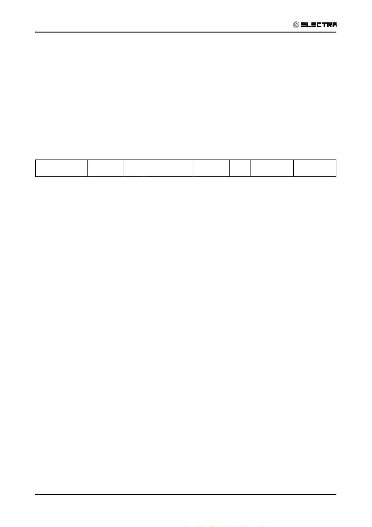
Service Manual
K DCI Inverter series
Indoor Units Outdoor Units
K 25 DCI INV ONG 25 DCI INV
K 35 DCI INV ONG 35 DCI INV
K 35S DCI INV ONG 35S DCI INV
K 50 DCI INV ONG 50 DCI INV
REFRIGERANT
R410A
DECEMBER 2004
HEAT PUMP
Page 2
LIST OF EFFECTIVE PAGES
LIST OF EFFECTIVE PAGES
Note: Changes in the pages are indicated by a “Revision#” in the footer of each effected page
(when none indicates no changes in the relevant page). All pages in the following list represent
effected/ non effected pages divided by chapters.
Dates of issue for original and changed pages are:
Original .......1 ........ 15 January 2005
Total number of pages in this publication is 70 consisting of the following:
Page
No.
Title ....................... 0
A ........................... 0
i ............................. 0
1-1 - 1-4 ................ 0
2-1 - 2-4 ................ 0
3-1 - 3-2 ................ 0
4-1 - 4-2 ................ 0
5-1 - 5-12 .............. 0
6-1 - 6-8 ................ 0
7-1 - 7-2 ................ 0
8-1 - 8-2 ................ 0
9-1 - 9-2 ................ 0
10-1-10-2 .............. 0
11-1-11-16 ............. 0
12-1-12-8 .............. 1
13-1-13-10 ............ 0
Appendix -A ...........0
Revision
No. #
Page
No.
Revision
No. #
Page
No.
Revision
No. #
• Zero in this column indicates an original page.
*Due to constant improvements please note that the data on this service manual can be modified with out notice.
**Photos are not contractual.
A
Revision Y05-02
Service Manual − K DCI
Page 3
TABLE OF CONTENTS
Table of Contents
1. INTRODUCTION ...................................................................................................1-1
2. PRODUCT DATA SHEET ......................................................................................2-1
3. RATING CONDITIONS ..........................................................................................3-1
4. OUTLINE DIMENSIONS .......................................................................................4-1
5. PERFORMANCE DATA .......................................................................................5-1
6. PRESSURE CURVES ...........................................................................................6-1
7. ELECTRICAL DATA ..............................................................................................7-1
8. WIRING DIAGRAMS .............................................................................................8-1
9. REFRIGERATION DIAGRAMS .............................................................................9-1
10. TUBING CONNECTIONS ......................................................................................10-1
11. CONTROL SYSTEM .............................................................................................11-1
12. TROUBLESHOOTING ..........................................................................................12-1
13.
EXPLODED VIEWS AND SPARE PARTS LISTS .................................................13-1
14. APPENDIX A
Revision Y05-02Service Manual - K DCI
i
Page 4

1. INTRODUCTION
CONTENTS
1.1 General
The new K DCI INVERTERS split Cassette range comprise the following RC (heat
pump) models:
• K 25 DCI INV
• K 35 DCI INV
• K 35S DCI INV
• K 50 DCI INV
The New DCI K units can be easly fitted to resedential and comercial aplications
featuring esthetic design, compact dimensions, and low noise operation.
1.2 Main Features
INTRODUCTION
The K DCI INV series benefits from the most advanced technological innovations,
namely:
• DC Inverter technolegy
• R410a
• High COP (level A)
• Lego Concept
• Pre-Charged units up to the max’ alowing tubing distance
• Networking system connectivity
• Base heater connection
• Cooling operation at outdoor temperature down to -10ºC
• Heating operation at outdoor temperature down to -15ºC
• Bended indoor coil with treated aluminum fins and coating for improved
efficiency.
• Easy access to the interconnecting tubing and wiring connections.
• Automatic treated air sweep.
• Low indoor and outdoor noise levels.
• Easy installation and service.
Revision Y05-02Service Manual - K DCI
1-1
Page 5
INTRODUCTION
CONTENTSCONTENTS
1.3 Filtration
The WNG DCI INV series presents several types of air filters:
• Easily accessible, and re-usable pre-filters (mesh)
• Pre-charged electrostatic filter (disposable)
• Active carbon filter (disposable)
1.4 Control
The microprocessor indoor and outdoor controllers, and an infrared remote control,
supplied as standard, provide complete operating function and programming.
Remote controlers: RC-2/3/4/5/7, RCW, µBMS
Networking system AircoNet version 4.2 and up, MIU SW version H8 and up
For further details please refer to the Operation Manual, Appendix A.
1.5 Outdoor Unit
The K DCI INV outdoor units can be installed as floor or wall mounted units by using a
wall supporting bracket. The metal sheets are protected by anti- corrosion paint work
allowing long life resistance. All outdoor units are pre-charged. For further information
please refer to the Product Data Sheet, Chapter 2.
• ONG 25 DCI
• ONG 35 DCI
• ONG 50
Outdoor Unit Features:
Features ONG 25,35, 50, DCI
Display 3 LED’s
Base Heater Optional
Outdoor Fan Variable Speed DC Inverter
M2L cable Port No
1.6 Tubing Connections
Flare type interconnecting tubing to be produced on site.
For further details please refer to the Installation Manual, Chapter 9.
1.7 Accessories
1.8 Inbox Documentation
1-2
• MIU (K) MODBUS Interface Unit
• Base heater
• M2L cable
Each unit is supplied with its own installation and operation manuals.
Revision Y05-02 Service Manual - K DCI
Page 6
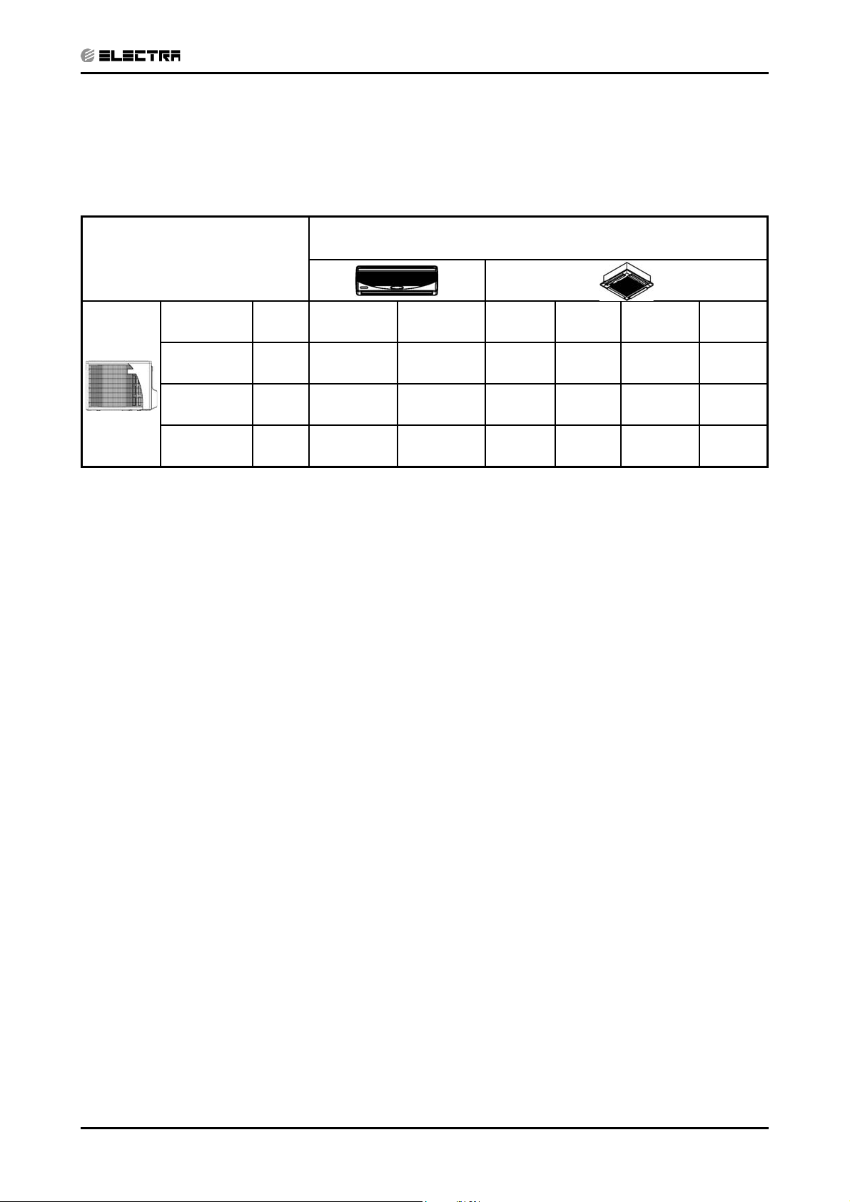
1.9 Matching Table
CONTENTSCONTENTS
1.9.1 R410A
OUTDOOR UNITS
MODEL REF” WNG25DCI WNG35 DCI K25 DCI K35 DCI K35S DCI K50 DCI
INTRODUCTION
INDOOR UNITS
ONG 25 DCI R410A
ONG 35 DCI R410A
0NG 50 DCI R410A
√√
√√√
√
The above table lists outdoor units and K indoor units which can be matched together. In addition
the listed outdoor units can be matched with other types of indoor units such as wall mounted,
For further information please refer to the relevant Service Manual.
Revision Y05-02Service Manual - K DCI
1-3
Page 7
PRODUCT DATA SHEET
CONTENTSCONTENTS
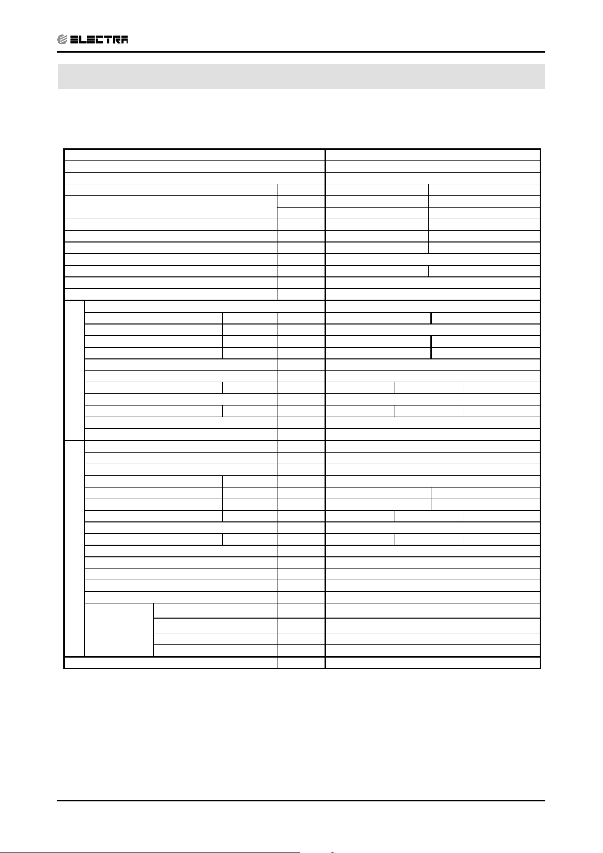
2. PRODUCT DATA SHEET
2.1 K25 DCI
Model Indoor Unit K25 DCI
Model Outdoor Unit ONG25 DCI
Installation Method Flare
Characteristics Units Cooling Heating
(1)
Capacity
Power Input
COP
Energy Efficiency Class A A
Power Supply V/Ph/Hz
Rated Current A
Starting Current A
Circuit Breaker Rating A 16
INDOOR
OUTDOOR
Operation Control Type IR Remote Control
(1)
(1)
W
W/W
Fan Type & Quantity Centrifugal*1
(2)
Airflow
H/M/L m3/hr
External Static Pressure Min-Max Pa N/A
Sound Power Level
Sound Pressure Level
Moisture Removal L/hr
Condensate Drain Tube I.D. mm 16
Dimensions W/H/D mm 571 287 571
Weight kg 22.7
Package Dimensions W/H/D mm 685 415 685
Units per Pallet Units 10
Stacking Height Units 5
Refrigerant Control Electronic Expansion Valve
Compressor Type, Model Single Rotary DC Inverter Panasonic 5RS102XAB
Fan Type & Quantity Axial *1
Airflow H m3/hr 1780
Sound Power Level H dB (A) 60 61
Sound Pressure Level
Dimensions W/H/D mm 795 610 290
Weight kg 40
Package Dimensions W/H/D mm 945 655 393
Units per Pallet Units 9
Stacking Height Units 3
Refrigerant Type R410A
Refrigerant Chargeless Distance g 1100
Additional Charge Per 1 Meter g/m No Need
Connections
Between Units
(3)
H/L dB (A)
(4)
H/L dB (A)
(4)
H dB (A) 50 51
Liquid Line
Suction Line
Max. Tubing Length m 20
Max. Height Difference m 10
Btu/hr
W
(mm)In
(mm)In
8530 (5120-12970) 11600 (5120-17060)
2500 (1500 - 3800) 3400 (1500 - 5000)
590 (420-1000) 915 (400-1500)
4.24 3.72
220-240V / 1Ph / 50Hz
2.7 4.2
10.50
570-500-435 600-530-450
42-48 42-47
32-38 32-37
1.0
(6.35)
¼”
(9.53)
”
(1) Rating conditions in accordance with ISO 5151 and ISO 13253 (for ducted units) and EN14511.
(2) Airflow in ducted units; at nominal external static pressure.
(3) Sound power in ducted units is measured at air discharge.
(4) Sound pressure level measured at 1 meter distance from unit.
Revision Y05-02Service Manual - K DCI
2-1
Page 8

PRODUCT DATA SHEET
CONTENTSCONTENTS
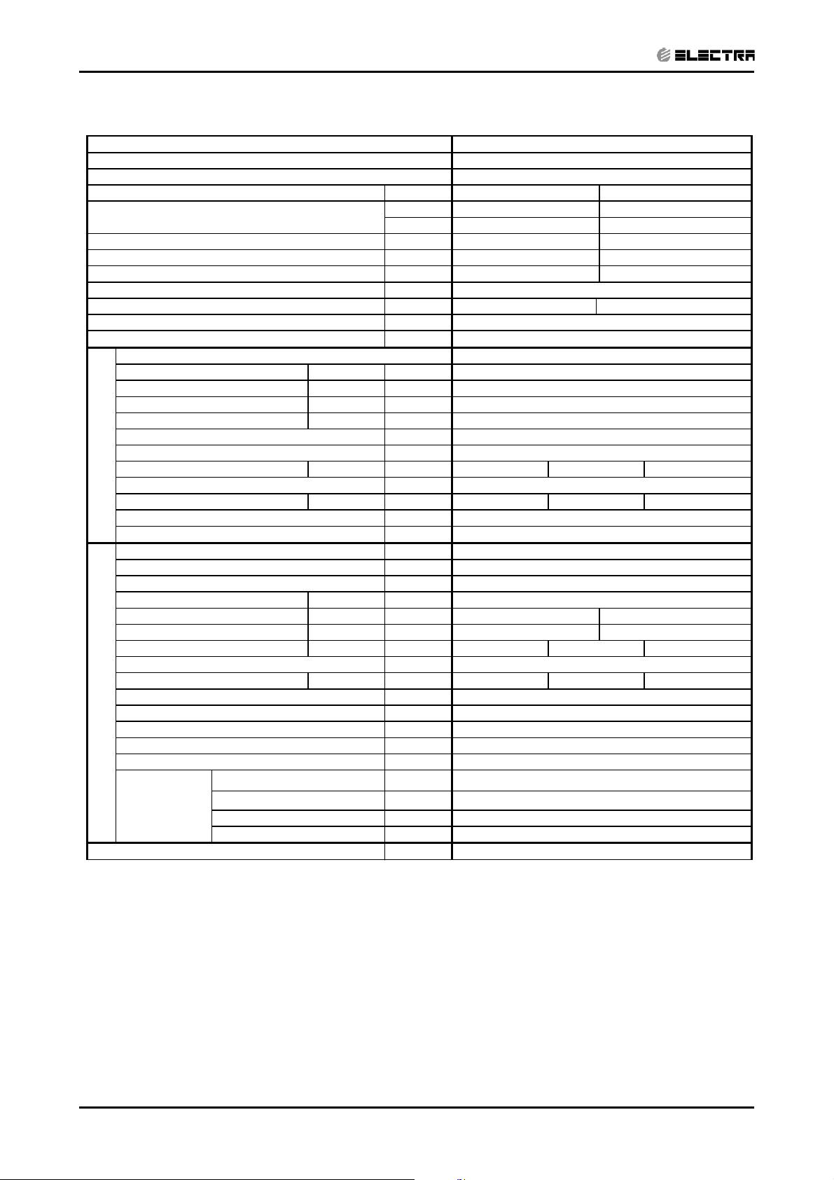
2.2 K35 DCI
Model Indoor Unit K35 DCI
Model Outdoor Unit ONG35 DCI
Installation Method Flare
Characteristics Units Cooling Heating
Capacity
Power Input
COP
Energy Efficiency Class A A
Power Supply V/Ph/Hz
Rated Current A
Starting Current A
Circuit Breaker Rating A 16
Operation Control Type IR Remote Control
(1)
(1)
(1)
INDOOR
OUTDOOR
W
W/W
Fan Type & Quantity Centrifugal*1
(2)
Airflow
H/M/L m3/hr
External Static Pressure Min-Max Pa N/A
Sound Power Level
Sound Pressure Level
Moisture Removal L/hr
Condensate Drain Tube I.D. mm 16
Dimensions W/H/D mm 571 287 571
Weight kg 24.4
Package Dimensions W/H/D mm 685 415 685
Units per Pallet Units 10
Stacking Height Units 5
Refrigerant Control Electronic Expansion Valve
Compressor Type, Model Single Rotary DC Inverter Panasonic 5RS102XAB
Fan Type & Quantity Axial *1
Airflow H m3/hr 1780
Sound Power Level H dB (A)
Sound Pressure Level
Dimensions W/H/D mm 795 610 290
Weight kg 40
Package Dimensions W/H/D mm 945 655 393
Units per Pallet Units 9
Stacking Height Units 3
Refrigerant Type R410A
Refrigerant Chargeless Distance g 1200
Additional Charge Per 1 Meter g/m No Need
Connections
Between Units
(3)
H/L dB (A)
(4)
H/L dB (A)
(4)
H dB (A)
Liquid Line
Suction Line
Max. Tubing Length m 20
Max. Height Difference m 10
Btu/hr
W
(mm)In
(mm)In
11940 (5100 - 14960) 14620 (5100 - 18700)
3500 (1500 - 4400) 4300 (1500 - 5500)
950 (420-1250) 1330 (400-1850)
3.68 3.23
220-240V / 1Ph / 50Hz
4.1 5.6
10.50
580-510-435 620-560-450
42-48 42-47
32-38 32-37
1.5
62 62
52 52
¼”
(6.35)
(9.53)
”
(1) Rating conditions in accordance with ISO 5151 and ISO 13253 (for ducted units) and EN14511.
(2) Airflow in ducted units; at nominal external static pressure.
(3) Sound power in ducted units is measured at air discharge.
(4) Sound pressure level measured at 1 meter distance from unit.
2-2
Revision Y05-02 Service Manual - K DCI
Page 9

PRODUCT DATA SHEET
CONTENTSCONTENTS
2.3 K35S DCI
Model Indoor Unit K35S DCI
Model Outdoor Unit ONG35 DCI
Installation Method Flare
Characteristics Units Cooling Heating
Capacity
Power Input
COP
Energy Efficiency Class A A
Power Supply V/Ph/Hz
Rated Current A
Starting Current A
Circuit Breaker Rating A 16
Operation Control Type IR Remote Control
(1)
(1)
(1)
INDOOR
OUTDOOR
W
W/W
Fan Type & Quantity Centrifugal*1
(2)
Airflow
H/M/L m3/hr
External Static Pressure Min-Max Pa N/A
Sound Power Level
Sound Pressure Level
Moisture Removal L/hr
Condensate Drain Tube I.D. mm 16
Dimensions W/H/D mm 571 287 571
Weight kg 24.4
Package Dimensions W/H/D mm 685 415 685
Units per Pallet Units 10
Stacking Height Units 5
Refrigerant Control Electronic Expansion Valve
Compressor Type, Model Single Rotary DC Inverter Panasonic 5RS102XAB
Fan Type & Quantity Axial *1
Airflow H m3/hr 1780
Sound Power Level H dB (A)
Sound Pressure Level
Dimensions W/H/D mm 795 610 290
Weight kg 40
Package Dimensions W/H/D mm 945 655 393
Units per Pallet Units 9
Stacking Height Units 3
Refrigerant Type R410A
Refrigerant Chargeless Distance g 1200
Additional Charge Per 1 Meter g/m No Need
Connections
Between Units
(3)
H/L dB (A)
(4)
H/L dB (A)
(4)
H dB (A)
Liquid Line
Suction Line
Max. Tubing Length m 20
Max. Height Difference m 10
Btu/hr
W
(mm)In
(mm)In
11940 (5800 - 16380) 15300 (5780-19720)
3500 (1700 - 4800) 4500 (1700 - 5800)
870 (460 - 1300) 1180 (350-1580)
4.02 3.81
220-240V / 1Ph / 50Hz
4.0 5.4
10.50
580-510-435 620-560-450
42-49 42-48
32-38 32-38
1.5
62 62
52 52
¼”
(6.35)
(9.53)
”
(1) Rating conditions in accordance with ISO 5151 and ISO 13253 (for ducted units) and EN14511.
(2) Airflow in ducted units; at nominal external static pressure.
(3) Sound power in ducted units is measured at air discharge.
(4) Sound pressure level measured at 1 meter distance from unit.
Revision Y05-02Service Manual - K DCI
2-3
Page 10
PRODUCT DATA SHEET
CONTENTSCONTENTS
2.4 K50 DCI
Model Indoor Unit K50 DCI
Model Outdoor Unit ONG35 DCI
Installation Method Flare
Characteristics Units Cooling Heating
Capacity
Power Input
COP
Energy Efficiency Class A A
Power Supply V/Ph/Hz
Rated Current A
Starting Current A
Circuit Breaker Rating A 16
Operation Control Type IR Remote Control
(1)
(1)
(1)
INDOOR
OUTDOOR
W
W/W
Fan Type & Quantity Centrifugal*1
(2)
Airflow
H/M/L m3/hr
External Static Pressure Min-Max Pa N/A
Sound Power Level
Sound Pressure Level
Moisture Removal L/hr
Condensate Drain Tube I.D. mm 16
Dimensions W/H/D mm 571 287 571
Weight kg 28
Package Dimensions W/H/D mm 685 415 685
Units per Pallet Units 10
Stacking Height Units 5
Refrigerant Control Electronic Expansion Valve
Compressor Type, Model SCROLL Panasonic 5CS130XCC03
Fan Type & Quantity Axial *1
Airflow H m3/hr 2160
Sound Power Level H dB (A)
Sound Pressure Level
Dimensions W/H/D mm 795 610 290
Weight kg
Package Dimensions W/H/D mm 945 655 393
Units per Pallet Units 9
Stacking Height Units 3
Refrigerant Type R410A
Refrigerant Chargeless Distance g 1500
Additional Charge Per 1 Meter g/m No Need
Connections
Between Units
(3)
H/M/L dB (A)
(4)
H/M/L dB (A)
(4)
H dB (A)
Liquid Line
Suction Line
Max. Tubing Length m 30
Max. Height Difference m 10
Btu/hr
W
(mm)In
(mm)In
17060 (4610 – 21840) 21500 (4610 - 25590)
5000 (1350 – 6400) 6300 (1350 – 7500)
1550 (530 – 2000) 1740 (350 – 2080)
3.23 3.62
220-240V / 1Ph / 50Hz
7.1 8.0
10.50
730-630-510
46 – 55 - 59
36 – 44 - 48.5
2
62 63
52 53
43
(6.35)
¼”
(12.7)
½”
2-4
(1) Rating conditions in accordance with ISO 5151 and ISO 13253 (for ducted units) and EN14511.
(2) Airflow in ducted units; at nominal external static pressure.
(3) Sound power in ducted units is measured at air discharge.
(4) Sound pressure level measured at 1 meter distance from unit.
Revision Y05-02 Service Manual - K DCI
Page 11

3. RATING CONDITIONS
CONTENTSCONTENTS
Standard conditions in accordance with ISO 5151, ISO 13253 (for ducted units)
and EN 14511.
RATING CONDITIONS
Cooling:
Indoor: 27
Outdoor: 35
o
C DB 19oC WB
o
C DB
Heating:
Indoor: 20
Outdoor: 7
o
C DB
o
C DB 6oC WB
3.1 Operating Limits
Cooling
Heating
Voltage
Upper limit
Lower limit 21oC DB 15oC WB -10oC DB
Upper limit
Lower limit 10oC DB -15oC DB -16oC WB
1PH
3PH N/A
Indoor Outdoor
32oC DB 23oC WB 46oC DB
27oC DB 24oC DB 18oC WB
198 – 264 V
Revision Y05-02Service Manual - K DCI
3-1
Page 12
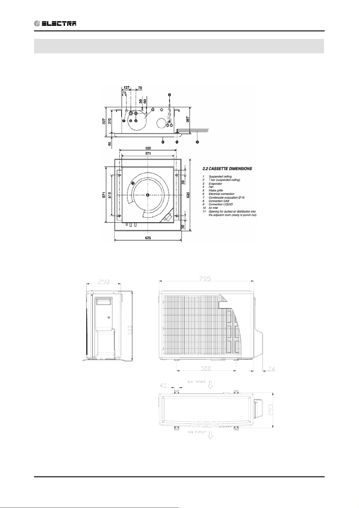
4. OUTLINE DIMENSIONS
CONTENTSCONTENTS
4.1 Indoor Unit: K 25, 35, 35S, 50 DCI
OUTLINE DIMENSIONS
4.2
Outdoor Unit: ONG 25, 35, 35S, 50 DCI
Revision Y05-02Service Manual - K DCI
4-1
Page 13
5. PERFORMANCE DATA
CONTENTSCONTENTS
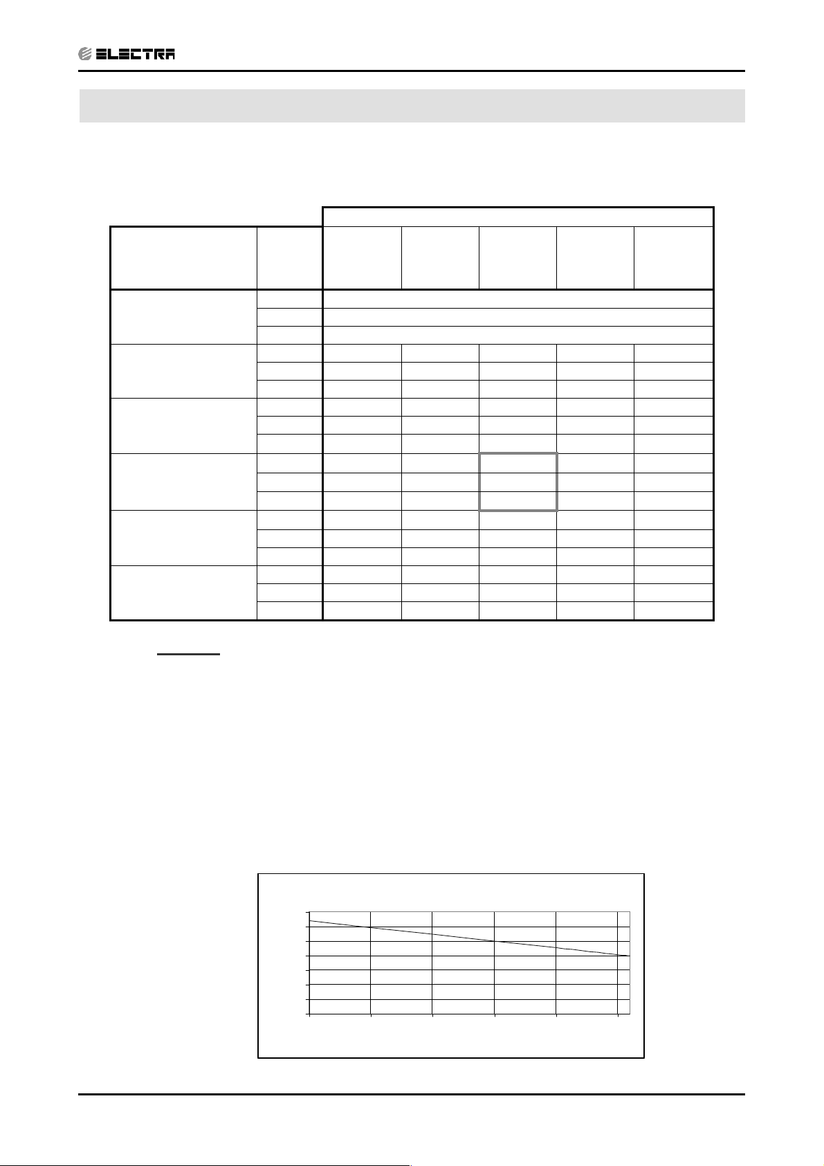
5.1 K25 DCI
5.1.1 Cooling Capacity (kW) - Run Mode
PERFORMANCE DATA
OD COIL
ENTERING AIR DB
TEMPERATURE [C
-10 - 20
(protection range)
25
30
35
40
46
ID COIL ENTERING AIR DB/WB TEMPERATURE [ºC]
DATA
0
]
22/15 24/17 27/19 29/21 32/23
TC 80 - 110 % of nominal
SC 80 - 105 % of nominal
PI 25 - 50 % of nominal
TC 2.42 2.57 2.73 2.89 3.05
SC 2.09 2.13 2.18 2.22 2.26
PI 0.46 0.47 0.48 0.49 0.50
TC 2.30 2.46 2.62 2.77 2.93
SC 2.04 2.08 2.12 2.17 2.21
PI 0.52 0.53
TC 2.18 2.34
0.54
2.50
0.54 0.55
2.66 2.82
SC 1.98 2.03 2.07 2.11 2.16
PI 0.57 0.58
TC 2.07 2.23
0.59
2.38
0.60 0.61
2.54 2.70
SC 1.93 1.97 2.02 2.06 2.10
PI 0.63 0.64 0.64 0.65 0.66
TC 1.93 2.09 2.24 2.40 2.56
SC 1.87 1.91 1.95 2.00 2.04
PI 0.69 0.70 0.71 0.72 0.73
LEGEND
TC – Total Cooling Capacity, kW
SC – Sensible Capacity, kW
PI – Power Input, kW
WB – Wet Bulb Temp., (
DB – Dry Bulb Temp., (
o
o
C)
C)
ID – Indoor
OD – Outdoor
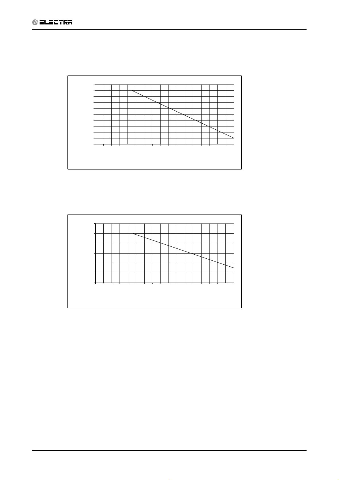
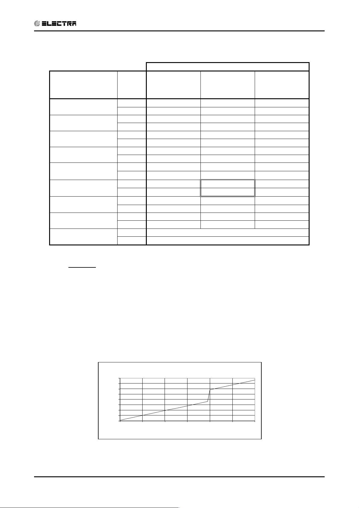
5.1.2 Capacity Correction Factors
Cooling Capacity Ratio Vs. Outdoor Temperature
1.2
1.1
1
0.9
0.8
0.7
Capacity Ration
0.6
0.5
20 25 30 35 40 45
Outdoor T emperature [deg C]
Revision Y05-02Service Manual - K DCI
5-1
Page 14

PERFORMANCE DATA
CONTENTSCONTENTS
5.1.3 Heating Capacity (kW) - Run Mode
ID COIL ENTERING AIR DB TEMPERATURE [ºC]
OD COIL
ENTERING AIR DB/
WB TEMPERATURE
[ºC]
-15/-16
-10/-12
-7/-8
-1/-2
2/1
7/6
10/9
15/12
15-24
(Protection Range)
DATA 15 20 25
TC 2.16 2.01 1.86
PI 0.55 0.60 0.66
TC 2.41 2.26 2.11
PI 0.66 0.72 0.77
TC 2.59 2.44 2.29
PI 0.75 0.80 0.86
TC 2.68 2.53 2.38
PI 0.79 0.84 0.90
TC 2.75 2.59 2.44
PI 0.82
TC 3.55
PI 0.86
TC 3.75
PI 0.91 0.97 1.02
TC 3.94 3.79 3.64
PI 0.96 1.02 1.07
TC 85 - 105 % of nominal
PI 80 - 120 % of nominal
0.87
3.40
0.92
3.60
0.93
3.25
0.97
3.44
LEGEND
TC – Total Cooling Capacity, kW
PI – Power Input, kW
WB – Wet Bulb Temp., (
DB – Dry Bulb Temp., (
o
o
C)
C)
ID – Indoor
OD – Outdoor
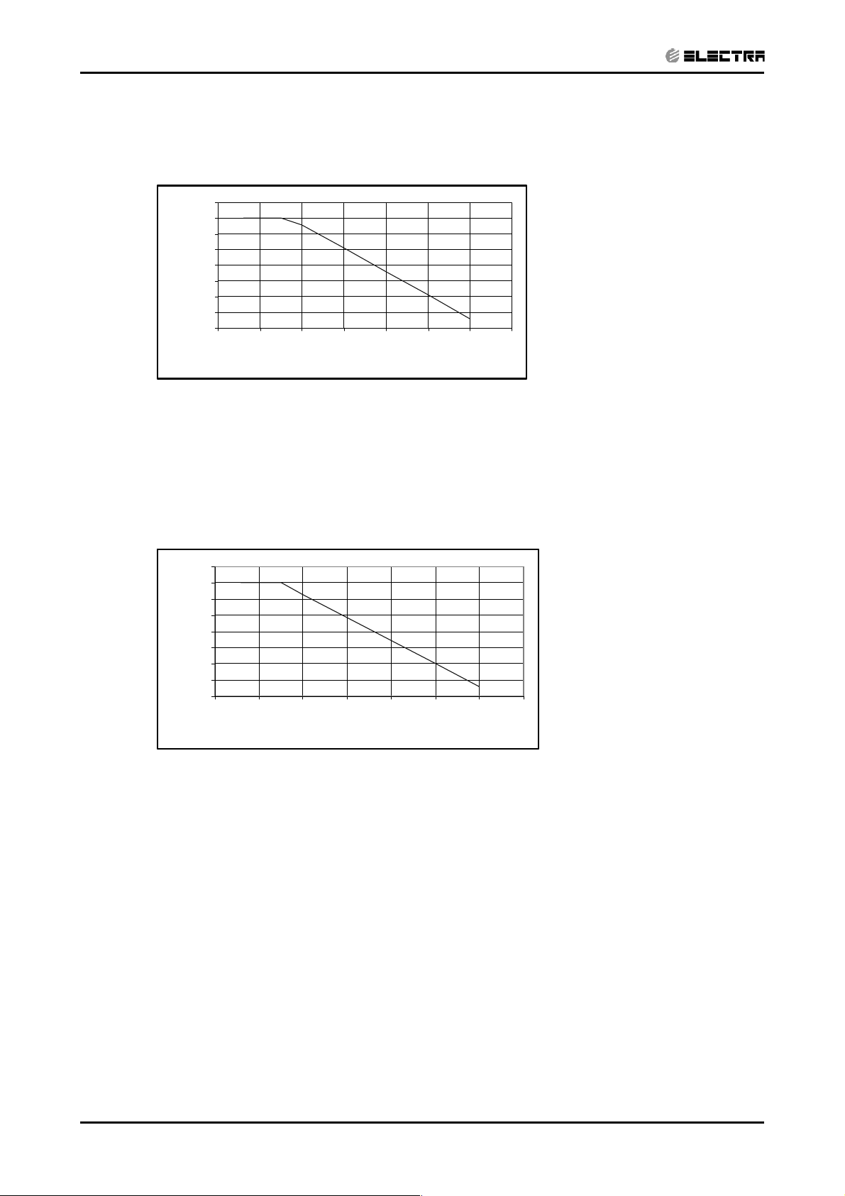
5.1.4 Capacity Correction Factors
Heating Capacity Ratio Vs. Outdoor Temperature
1.2
1.1
1
0.9
0.8
0.7
Capacity Rat ion
0.6
0.5
-15 -10 -5 0 5 10 15
Outdoor WB Temperature [deg C]
5-2
Revision Y05-02 Service Manual - K DCI
Page 15
PERFORMANCE DATA
CONTENTSCONTENTS
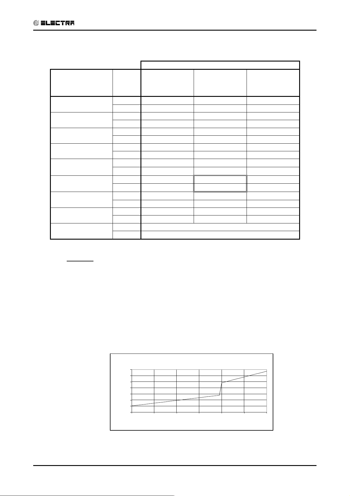
5.2 Capacity Correction Factor Due to Tubing Length
5.2.1 Cooling
1.01
1.00
0.99
0.98
0.97
0.96
0.95
0.94
Capacity Ratio
0.93
0.92
0.91
3 4 5 6 7 8 9 1011121314151617181920
Tubing Length [m]
5.2.2 Heating
1.02
1.00
0.98
0.96
0.94
Capacity Ratio
0.92
0.90
34567891011121314151617181920
Tubing Length [m]
Revision Y05-02Service Manual - K DCI
5-3
Page 16
PERFORMANCE DATA
CONTENTSCONTENTS
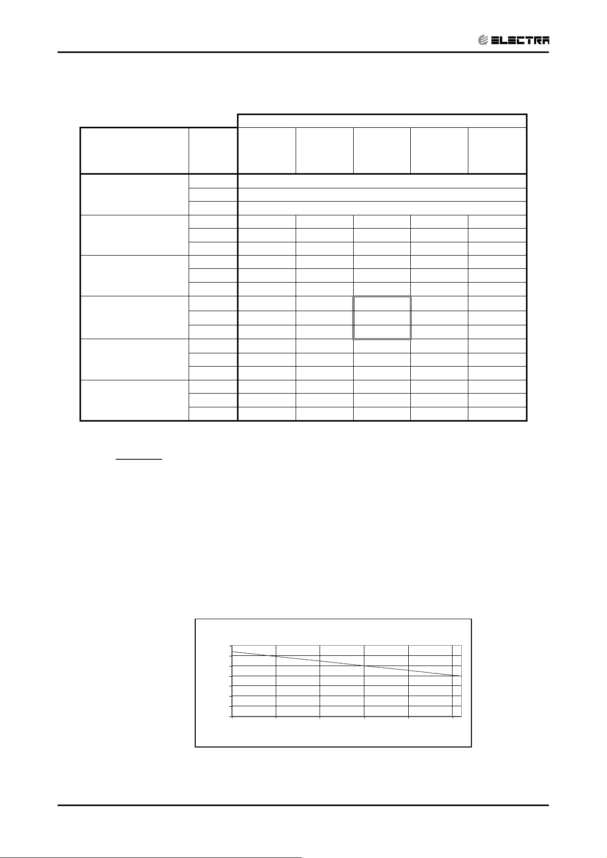
5.3 K35 DCI
5.3.1 Cooling Capacity (kW) - Run Mode
OD COIL
ENTERING AIR DB
TEMPERATURE [ºC]
-10 - 20
(protection range)
25
30
35
40
46
ID COIL ENTERING AIR DB/WB TEMPERATURE [ºC]
DATA
22/15 24/17 27/19 29/21 32/23
TC 80 - 110 % of nominal
SC 80 - 105 % of nominal
PI 25 - 50 % of nominal
TC 3.38 3.60 3.83 4.05 4.27
SC 2.65 2.70 2.75 2.81 2.86
PI 0.75 0.76 0.78 0.79 0.80
TC 3.22 3.44 3.66 3.88 4.11
SC 2.58 2.63 2.69 2.74 2.79
PI 0.83 0.85
TC 3.06 3.28
0.86
3.50
0.88 0.89
3.72 3.94
SC 2.51 2.57 2.62 2.67 2.73
PI 0.92 0.94
TC 2.89 3.12
0.95
3.34
0.96 0.98
3.56 3.78
SC 2.45 2.50 2.55 2.61 2.66
PI 1.01 1.02 1.04 1.05 1.07
TC 2.70 2.92 3.14 3.36 3.58
SC 2.37 2.42 2.47 2.53 2.58
PI 1.11 1.13 1.14 1.16 1.17
LEGEND
TC – Total Cooling Capacity, kW
SC – Sensible Capacity, kW
PI – Power Input, kW
WB – Wet Bulb Temp., (
DB – Dry Bulb Temp., (
o
o
C)
C)
ID – Indoor
5.3.2 Capacity Correction Factors
Cooling Capacity Ratio Vs. Outdoor Temperature
1.2
1.1
1
0.9
0.8
0.7
Capacity Rat ion
0.6
0.5
20 25 30 35 40 45
Outdoor T emperature [deg C]
5-4
Revision Y05-02 Service Manual - K DCI
Page 17
5.3.3 Heating Capacity (kW) - Run Mode
CONTENTSCONTENTS
ID COIL ENTERING AIR DB TEMPERATURE [ºC]
OD COIL
ENTERING AIR DB/
WB TEMPERATURE
[ºC]
-15/-16
-10/-12
-7/-8
-1/-2
2/1
7/6
10/9
15/12
15-24
(Protection Range)
DATA 15 20 25
TC 2.74 2.55 2.35
PI 0.80 0.88 0.96
TC 3.05 2.86 2.66
PI 0.96 1.04 1.12
TC 3.28 3.09 2.90
PI 1.09 1.17 1.25
TC 3.39 3.20 3.01
PI 1.15 1.23 1.31
TC 3.47 3.28 3.09
PI 1.19
TC 4.49
PI 1.25
TC 4.74
PI 1.32 1.40 1.49
TC 4.99 4.80 4.60
PI 1.40 1.48 1.56
TC 85 - 105 % of nominal
PI 80 - 120 % of nominal
1.27
4.30
1.33
4.55
PERFORMANCE DATA
1.35
4.11
1.41
4.36
LEGEND
TC – Total Cooling Capacity, kW
PI – Power Input, kW
o
WB – Wet Bulb Temp., (
DB – Dry Bulb Temp., (
o
C)
C)
ID – Indoor
OD – Outdoor
5.3.4 Capacity Correction Factors
Heating Capacity Ratio Vs. Outdoor Temperature
1.2
1.1
1
0.9
0.8
0.7
Capacity Rat ion
0.6
0.5
-15 -10 -5 0 5 10 15
Outdoor WB Temperature [de g C]
Revision Y05-02Service Manual - K DCI
5-5
Page 18
PERFORMANCE DATA
CONTENTSCONTENTS
5.4 Capacity Correction Factor Due to Tubing Length
5.4.1 Cooling
1.01
1.00
0.99
0.98
0.97
0.96
0.95
0.94
Capacity Ratio
0.93
0.92
0.91
3 4 5 6 7 8 9 1011121314151617181920
Tubing Length [m]
5.4.2 Heating
1.02
1.00
0.98
0.96
0.94
Capacity Ratio
0.92
0.90
3 4 5 6 7 8 9 1011121314151617181920
Tubing Length [m]
5-6
Revision Y05-02 Service Manual - K DCI
Page 19
5.5 K35S DCI
CONTENTSCONTENTS
5.5.1 Cooling Capacity (kW) - Run Mode
PERFORMANCE DATA
OD COIL
ENTERING AIR DB
TEMPERATURE [ºC]
-10 - 20
(protection range)
25
30
35
40
46
ID COIL ENTERING AIR DB/WB TEMPERATURE [ºC]
DATA
22/15 24/17 27/19 29/21 32/23
TC 80 - 110 % of nominal
SC 80 - 105 % of nominal
PI 25 - 50 % of nominal
TC 3.38 3.60 3.83 4.05 4.27
SC 2.65 2.70 2.75 2.81 2.86
PI 0.68 0.70 0.71 0.72 0.74
TC 3.22 3.44 3.66 3.88 4.11
SC 2.58 2.63 2.69 2.74 2.79
PI 0.76 0.78
TC 3.06 3.28
0.79
3.50
0.80 0.82
3.72 3.94
SC 2.51 2.57 2.62 2.67 2.73
PI 0.84 0.86
TC 2.89 3.12
0.87
3.34
0.88 0.90
3.56 3.78
SC 2.45 2.50 2.55 2.61 2.66
PI 0.92 0.94 0.95 0.96 0.98
TC 2.70 2.92 3.14 3.36 3.58
SC 2.37 2.42 2.47 2.53 2.58
PI 1.02 1.03 1.05 1.06 1.07
LEGEND
TC – Total Cooling Capacity, kW
SC – Sensible Capacity, kW
PI – Power Input, kW
WB – Wet Bulb Temp., (
DB – Dry Bulb Temp., (
o
o
C)
C)
ID – Indoor
OD – Outdoor
5.5.2 Capacity Correction Factors
Cooling Capacity Ratio Vs. Outdoor Temperature
1.2
1.1
1
0.9
0.8
0.7
Capacity Rat ion
0.6
0.5
20 25 30 35 40 45
Outdoor Te mperature [deg C]
Revision Y05-02Service Manual - K DCI
5-7
Page 20

PERFORMANCE DATA
CONTENTSCONTENTS
5.5.3 Heating Capacity (kW) - Run Mode
ID COIL ENTERING AIR DB TEMPERATURE [ºC]
OD COIL
ENTERING AIR DB/
WB TEMPERATURE
[ºC]
-15/-16
-10/-12
-7/-8
-1/-2
2/1
7/6
10/9
15/12
15-24
(Protection Range)
DATA 15 20 25
TC 2.86 2.66 2.46
PI 0.71 0.78 0.85
TC 3.19 2.99 2.79
PI 0.85 0.93 1.00
TC 3.43 3.23 3.03
PI 0.96 1.03 1.11
TC 3.55 3.35 3.15
PI 1.02 1.09 1.16
TC 3.63 3.43 3.23
PI 1.05
TC 4.70
PI 1.11
TC 4.96
PI 1.17 1.25 1.32
TC 5.22 5.02 4.82
PI 1.24 1.31 1.38
TC 85 - 105 % of nominal
PI 80 - 120 % of nominal
1.13
4.50
1.18
4.76
1.20
4.30
1.25
4.56
LEGEND
TC – Total Cooling Capacity, kW
PI – Power Input, kW
o
WB – Wet Bulb Temp., (
DB – Dry Bulb Temp., (
o
C)
C)
ID – Indoor
OD – Outdoor
5.5.4 Capacity Correction Factors
Heating Capacity Ratio Vs. Outdoor Temperature
1.2
1.1
1
0.9
0.8
0.7
Capacity Ration
0.6
0.5
-15 -10 -5 0 5 10 15
Outdoor WB Temperature [deg C]
5-8
Revision Y05-02 Service Manual - K DCI
Page 21
PERFORMANCE DATA
CONTENTSCONTENTS
15.6 Capacity Correction Factor Due to Tubing Length
5.6.1 Cooling
1.01
1.00
0.99
0.98
0.97
0.96
0.95
0.94
Capacity Ratio
0.93
0.92
0.91
3 4 5 6 7 8 9 1011121314151617181920
Tubing Length [m]
5.6.2 Heating
1.02
1.00
0.98
0.96
0.94
Capacity Ratio
0.92
0.90
3 4 5 6 7 8 9 1011121314151617181920
Tubing Length [m]
Revision Y05-02Service Manual - K DCI
5-9
Page 22
PERFORMANCE DATA
CONTENTSCONTENTS
5.7 K50 DCI
5.7.1 Cooling Capacity (kW) - Run Mode
OD COIL
ENTERING AIR DB
TEMPERATURE [ºC]
-10 - 20
(protection range)
25
30
35
40
46
ID COIL ENTERING AIR DB/WB TEMPERATURE [ºC]
DATA
22/15 24/17 27/19 29/21 32/23
TC 80 - 110 % of nominal
SC 80 - 105 % of nominal
PI 25 - 50 % of nominal
TC 4.85 5.13 5.42 5.70 5.99
SC 3.30 3.35 3.40 3.45 3.50
PI 1.20 1.23 1.26 1.28 1.31
TC 4.60 4.88 5.17 5.45 5.74
SC 3.17 3.22 3.27 3.32 3.37
PI 1.37 1.40
TC 4.35 4.63
1.42
4.92
1.45 1.48
5.20 5.49
SC 3.04 3.09 3.14 3.19 3.24
PI 1.54 1.56
TC 4.10 4.39
1.59
4.67
1.62 1.64
4.96 5.24
SC 2.91 2.96 3.01 3.06 3.11
PI 1.70 1.73 1.76 1.78 1.81
TC 3.80 4.09 4.37 4.66 4.94
SC 2.76 2.81 2.86 2.91 2.95
PI 1.90 1.93 1.96 1.98 2.01
LEGEND
TC – Total Cooling Capacity, kW
SC – Sensible Capacity, kW
PI – Power Input, kW
WB – Wet Bulb Temp., (
DB – Dry Bulb Temp., (
o
o
C)
C)
ID – Indoor
OD – Outdoor
5.7.2 Capacity Correction Factors
Cooling Capacity Ratio Vs. Outdoor Temperature
1.2
1.1
1
0.9
0.8
0.7
Capacity Ration
0.6
0.5
20 25 30 35 40 45
Outdoor Temperature [deg C]
5-10
Revision Y05-02 Service Manual - K DCI
Page 23
5.7.3 Heating Capacity (kW) - Run Mode
CONTENTSCONTENTS
ID COIL ENTERING AIR DB TEMPERATURE [ºC]
OD COIL ENTERING
AIR DB/WB
TEMPERATURE [ºC]
DATA 15 20 25
PERFORMANCE DATA
-15/-16
-10/-12
-7/-8
-1/-2
2/1
7/6
10/9
15/12
15-24
(Protection Range)
LEGEND
TC 2.66 2.28 1.90
PI 1.15 1.23 1.31
TC 3.52 3.13 2.75
PI 1.30 1.38 1.46
TC 4.16 3.77 3.39
PI 1.41 1.49 1.57
TC 4.47 4.09 3.71
PI 1.46 1.55 1.63
TC 4.69 4.30 3.92
PI 1.50
TC 6.24
PI 1.56
TC 6.56
1.58
5.85
1.64
6.18
1.66
5.47
1.72
5.79
PI 1.59 1.67 1.75
TC 6.88 6.50 6.12
PI 1.62 1.70 1.78
TC 85 - 105 % of nominal
PI 80 - 120 % of nominal
TC – Total Cooling Capacity, kW
PI – Power Input, kW
o
WB – Wet Bulb Temp., (
DB – Dry Bulb Temp., (
o
C)
C)
ID – Indoor
OD – Outdoor
5.7.4 Capacity Correction Factors
Heating Capacity Ratio Vs. Outdoor Temperature
1.2
1.1
1
0.9
0.8
0.7
0.6
Capacity Rat ion
0.5
0.4
-15 -10 -5 0 5 10 15
Outdoor WB Te mperature [deg C]
Revision Y05-02Service Manual - K DCI
5-11
Page 24
PERFORMANCE DATA
CONTENTSCONTENTS
5.8 Capacity Correction Factor Due to Tubing Length
5.8.1 Cooling
1.001
1.000
0.999
0.998
0.997
0.996
0.995
Capacity Ratio
0.994
0.993
0 5 10 15 20 25 30 35
Tubing Length[m]
5.8.2 Heating
1.02
1.00
0.98
0.96
0.94
0.92
0.90
Capacity Ratio
0.88
0.86
0 5 10 15 20 25 30 35
Tubing Length[m]
5-12
Revision Y05-02 Service Manual - K DCI
Page 25
6. PRESSURE CURVES
CONTENTSCONTENTS
6.1 Model: K 25 DCI
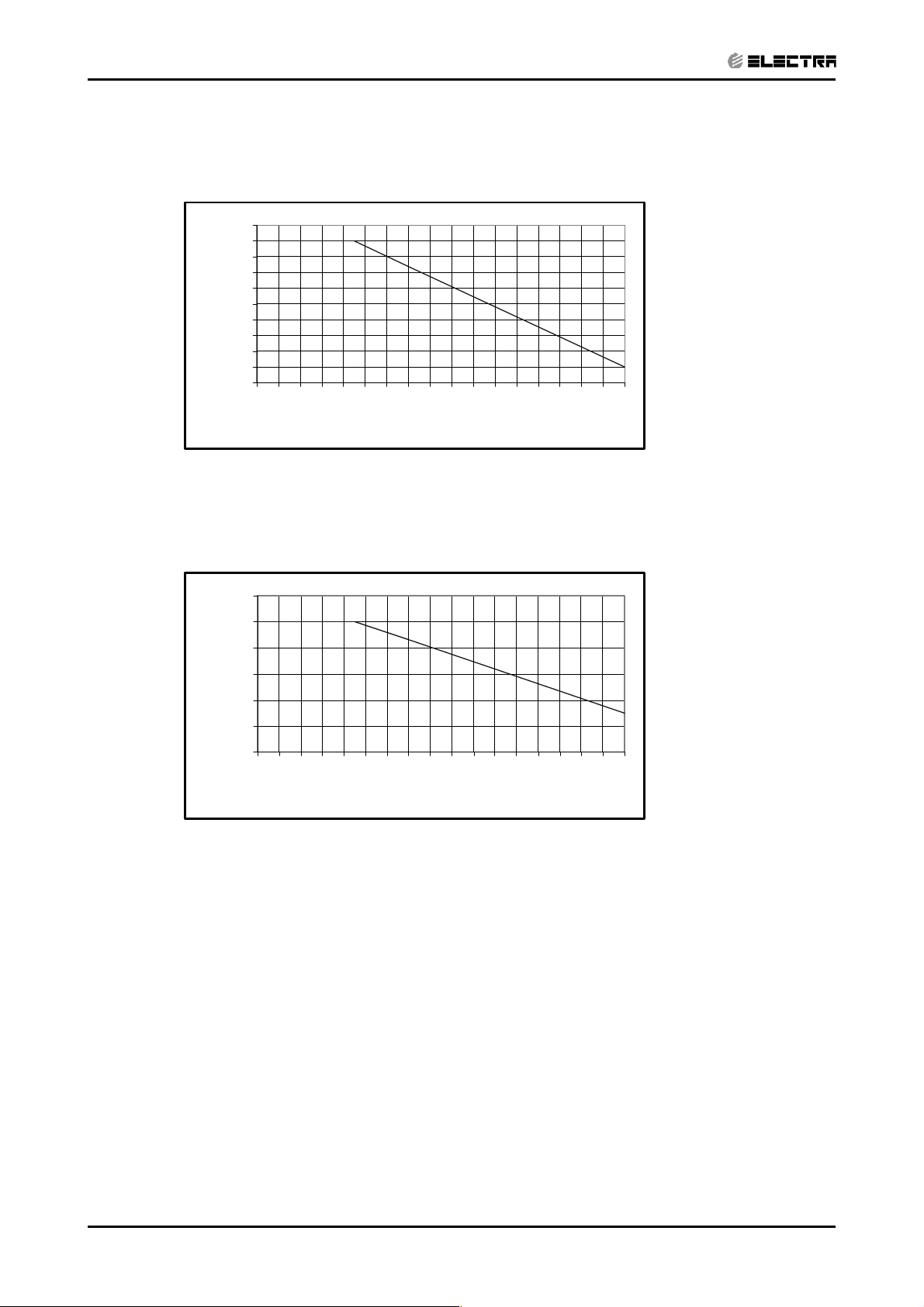
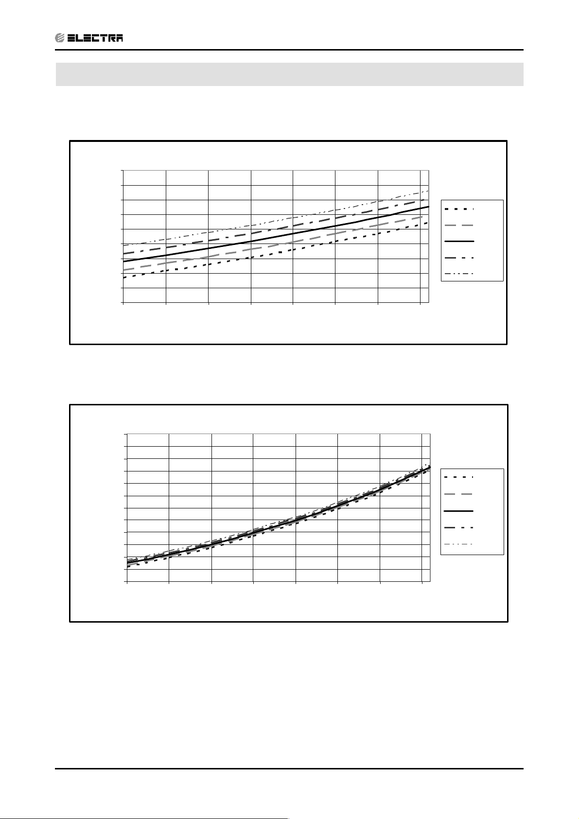
6.1.1 Cooling – Test Mode
Suction Pressure Vs.Outdoor Temp' - Cooling
1400
1300
1200
1100
1000
900
800
700
600
Suction Pressure [kPa]
500
10 15 20 25 30 35 40 45
PRESSURE CURVES
Indoor DB/WB
Temp.
22/15
24/17
27/19
29/21
32/23
Discharge Pressure [kPa]
Outdoor DB Temperature [ºC]
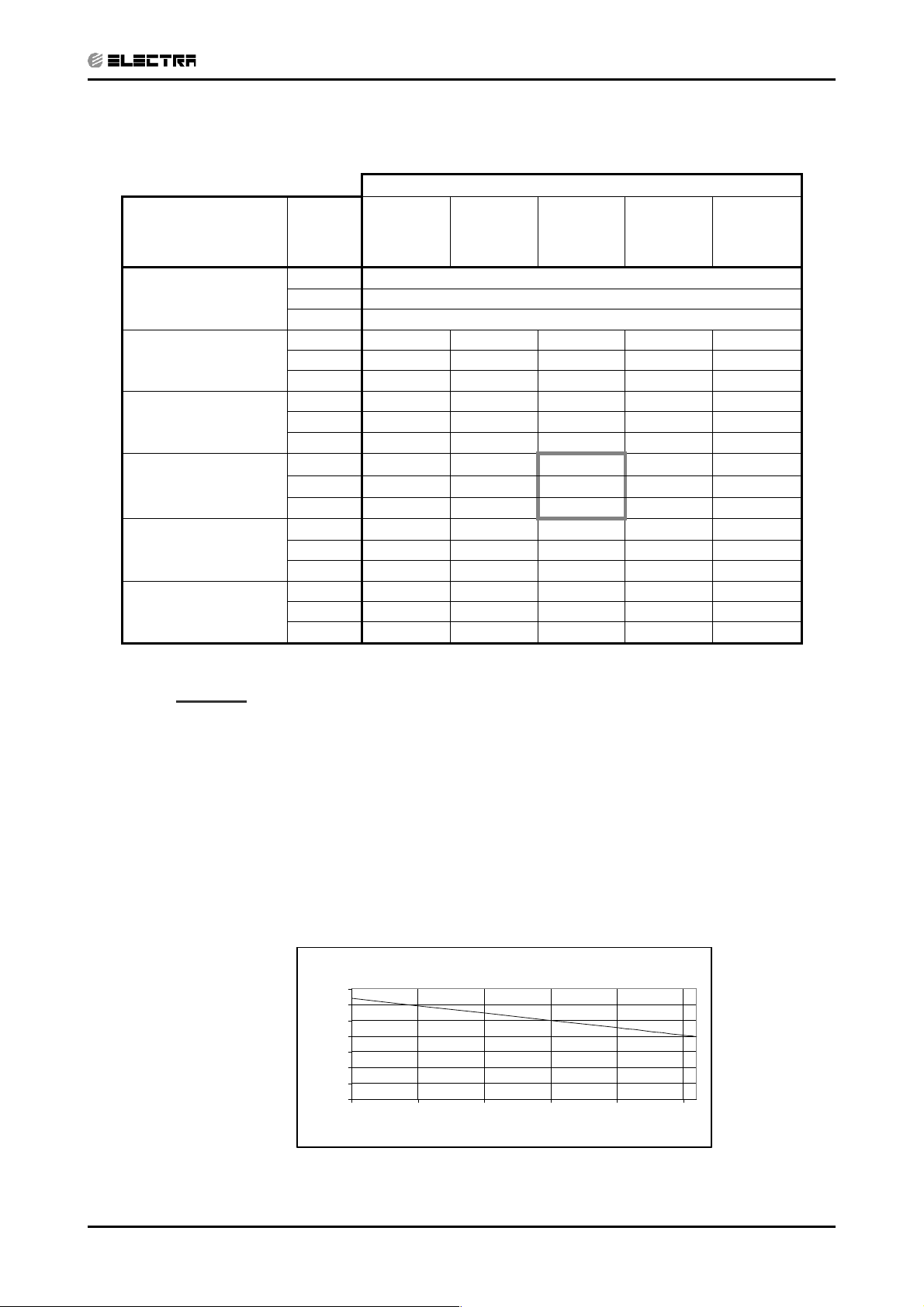
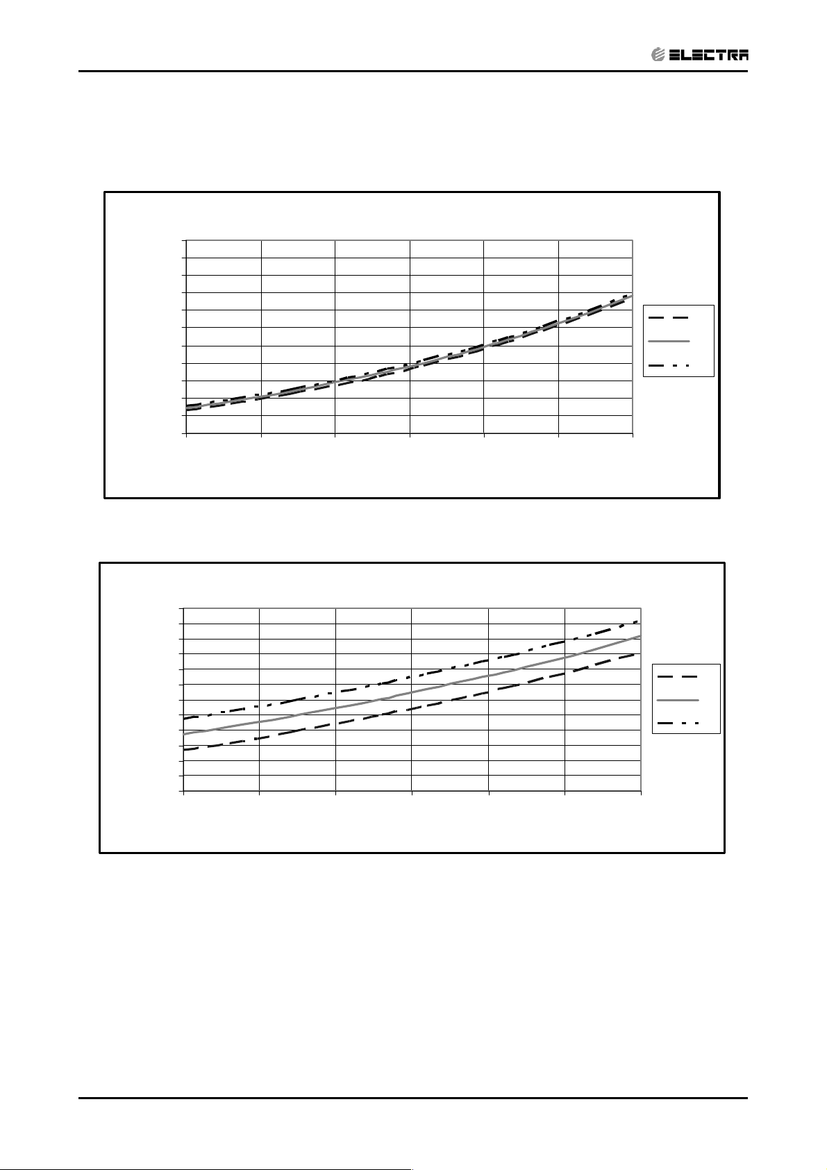
Discharge Pressure Vs.Outdoor Temp'- Cooling
4000
3750
3500
3250
3000
2750
2500
2250
2000
1750
1500
1250
1000
10 15 20 25 30 35 40 45
Outdoor DB Temperature [ºC]
Indoor
DB/W B
22/15
24/17
27/19
29/21
32/23
Revision Y05-02Service Manual - K DCI
6-1
Page 26
PRESSURE CURVES
CONTENTSCONTENTS
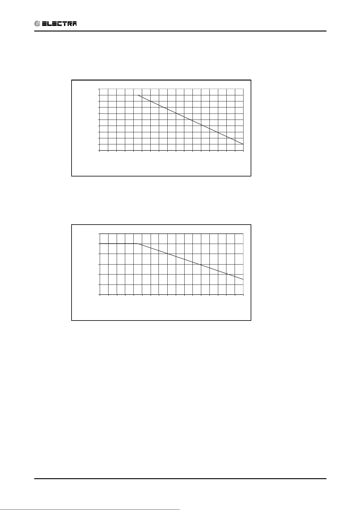
6.1.2 Heading – Test Mode
Suction Pressure Vs. Outdoor Temp' - Heating
1300
1200
1100
1000
900
800
700
600
500
400
Suction Pressure [kPa]
300
200
-15 -10 -5 0 5 10 15
Outdoor WB Temperature[ºC]
Indoor DB
15
20
25
Discharge Pressure [kPa]
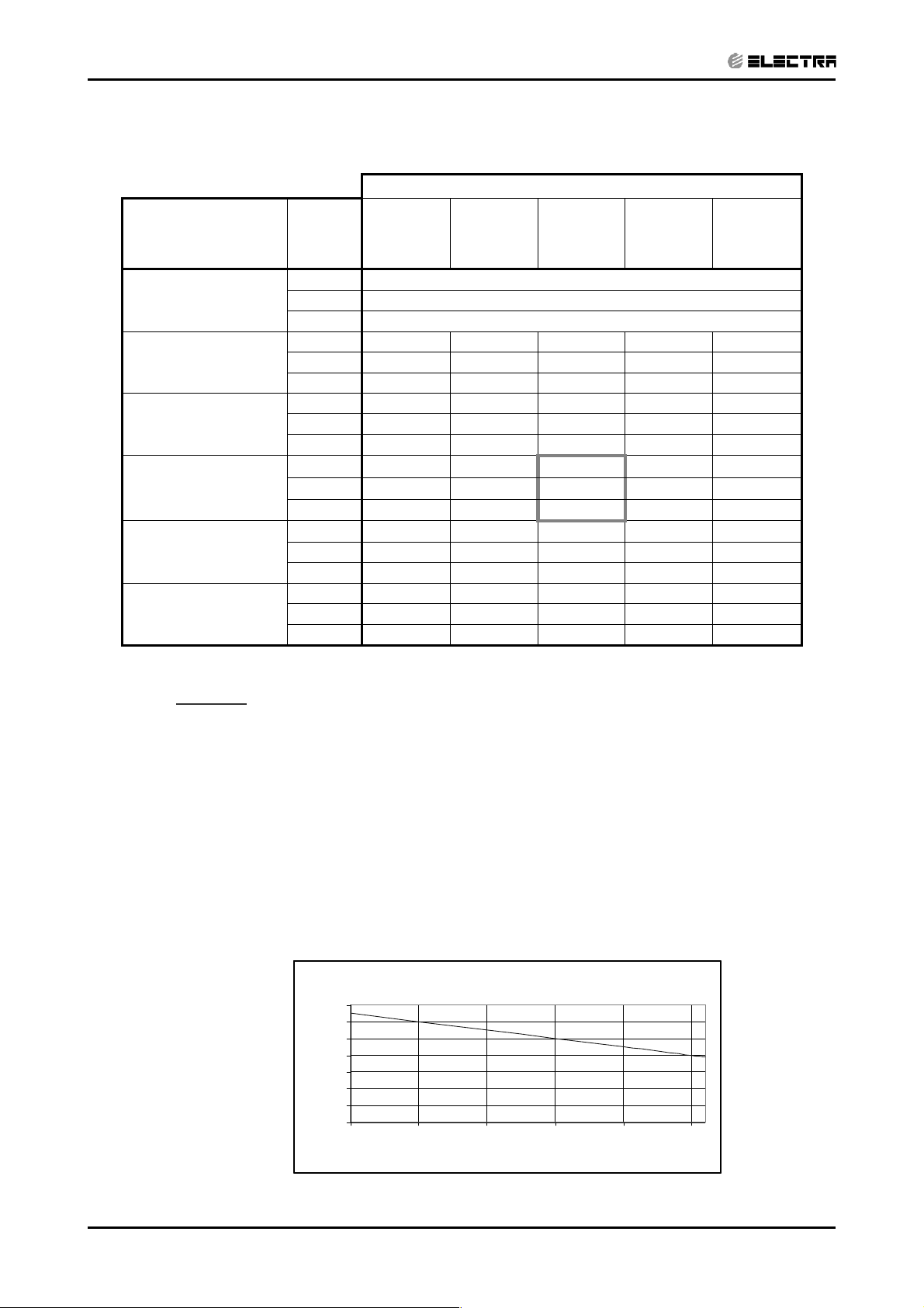
Discharge Pressure Vs.Outdoor Temp'- Heating
4000
3750
3500
3250
3000
2750
2500
2250
2000
1750
1500
1250
1000
-15 -10 -5 0 5 10 15
Outdoor WB Temperature [ºC]
Indoor DB
15
20
25
6-2
Revision Y05-02 Service Manual - K DCI
Page 27
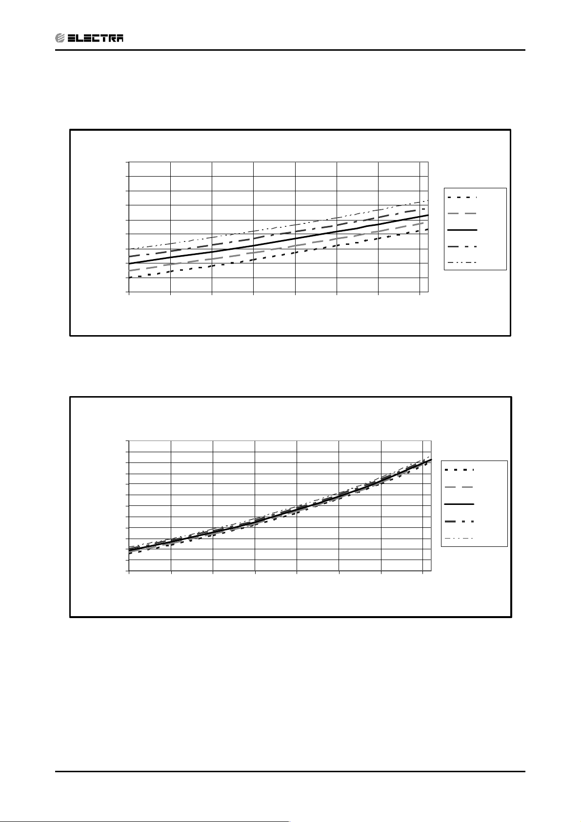
6.2 Model: K 35 DCI
CONTENTSCONTENTS
6.2.1 Cooling – Test Mode
Suction Pressure Vs.Outdoor Temp' - Cooling
PRESSURE CURVES
Suction Pressure [kPa]
Discharge Pressure [kPa]
1400
1300
1200
1100
1000
900
800
700
600
500
10 15 20 25 30 35 40 45
Outdoor DB Temperature [ºC]
Discharge Pressure Vs.Outdoor Temp'- Cooling
4000
3750
3500
3250
3000
2750
2500
2250
2000
1750
1500
1250
1000
10 15 20 25 30 35 40 45
Indoor
DB/W B
22/15
24/17
27/19
29/21
32/23
Indoor
DB/WB
22/15
24/17
27/19
29/21
32/23
Outdoor DB Temperature [ºC]
Revision Y05-02Service Manual - K DCI
6-3
Page 28
PRESSURE CURVES
CONTENTSCONTENTS
6.2.2 Heating – Test Mode
Suction Pressure Vs.Outdoor Temp' - Cooling
Suction Pressure [kPa]
Discharge Pressure [kPa]
1400
1300
1200
1100
1000
900
800
700
600
500
10 15 20 25 30 35 40 45
Outdoor DB Temperature [ºC]
Discharge Pressure Vs.Outdoor Temp'- Cooling
4000
3750
3500
3250
3000
2750
2500
2250
2000
1750
1500
1250
1000
10 15 20 25 30 35 40 45
Indoor
DB/W B
22/15
24/17
27/19
29/21
32/23
Indoor
DB/WB
22/15
24/17
27/19
29/21
32/23
6-4
Outdoor DB Temperature [ºC]
Revision Y05-02 Service Manual - K DCI
Page 29
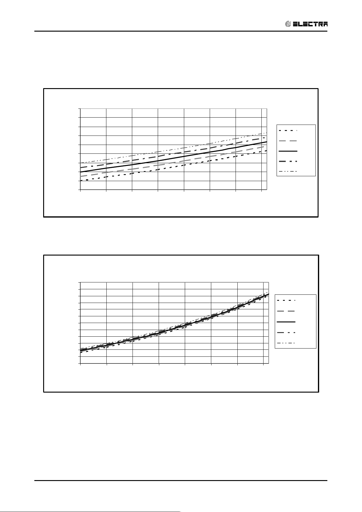
6.3 Model: K 35S DCI
CONTENTSCONTENTS
6.3.1 Cooling – Test Mode
Suction Pressure Vs.Outdoor Temp' - Cooling
1400
1300
1200
1100
1000
900
800
700
600
Suction Pressure [kPa]
500
10 15 20 25 30 35 40 45
PRESSURE CURVES
Indoor
DB/WB
22/15
24/17
27/19
29/21
32/23
Discharge Pressure [kPa]
Outdoor DB Temperature[ºC]
Discharge Pressure Vs.Outdoor Temp' - Cooling
4000
3750
3500
3250
3000
2750
2500
2250
2000
1750
1500
1250
1000
10 15 20 25 30 35 40 45
Outdoor DB Temperature[ºC]
Indoor
DB/WB
22/15
24/17
27/19
29/21
32/23
Revision Y05-02Service Manual - K DCI
6-5
Page 30

PRESSURE CURVES
CONTENTSCONTENTS
6.3.2 Heating – Test Mode
Suction Pressure Vs.Outdoor Temp' - Heating
1300
1200
1100
1000
900
800
700
600
500
400
Suction Pressure [kPa]
300
200
-15 -10 -5 0 5 10 15
Indoor DB
15
20
25
Discharge Pressure [kPa]
Outdoor WB Temperature[ºC]
Discharge Pressure Vs.Outdoor Temp' - Heating
4000
3750
3500
3250
3000
2750
2500
2250
2000
1750
1500
1250
1000
-15 -10 -5 0 5 10 15
Outdoor WB Temperature[ºC]
Indoor DB
15
20
25
6-6
Revision Y05-02 Service Manual - K DCI
Page 31

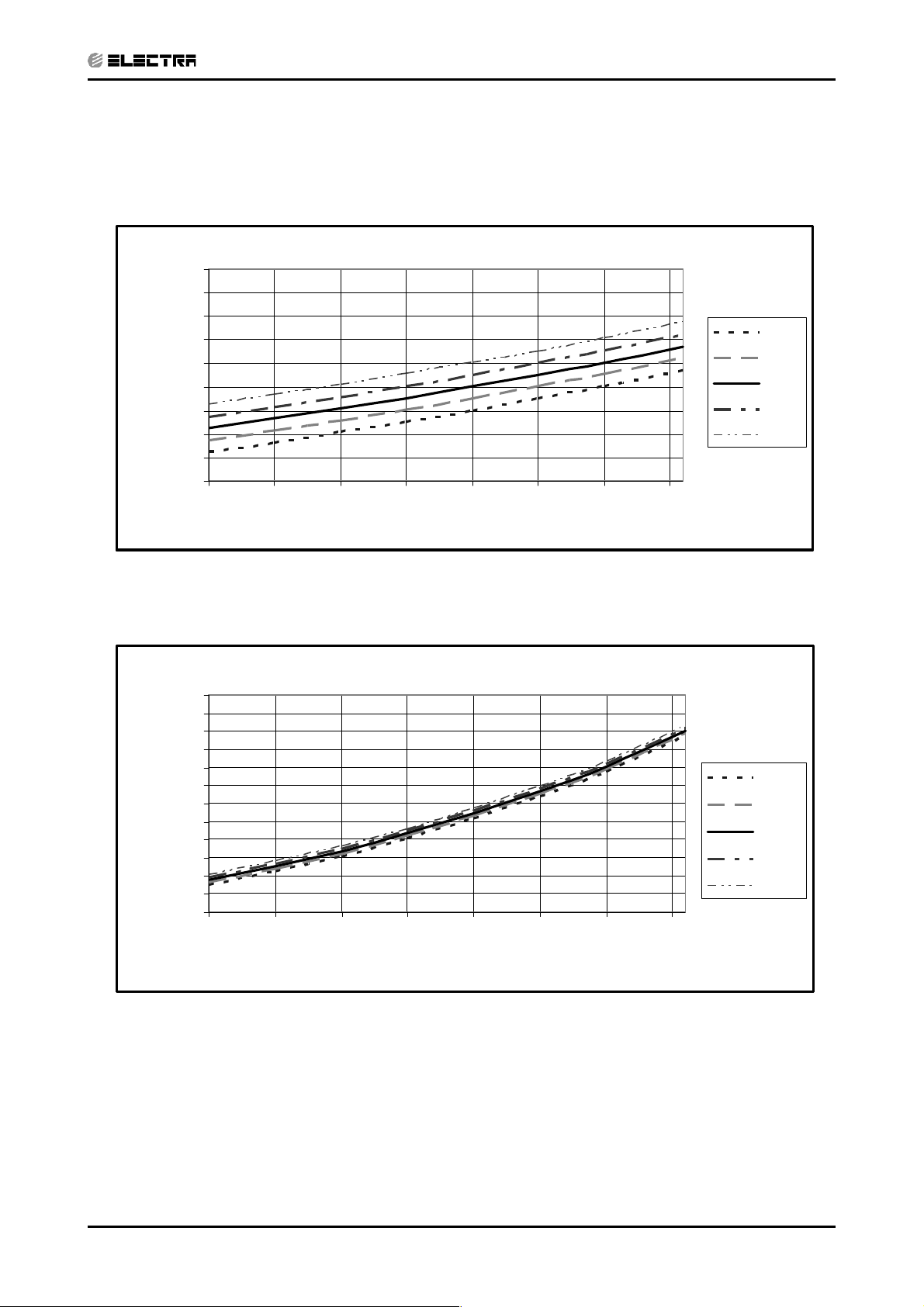
6.4 Model: K 50 DCI
CONTENTSCONTENTS
6.4.1 Cooling – Test Mode
Suction Pressure Vs.Outdoor Temp' - Cooling
1400
1300
1200
1100
1000
900
800
700
600
Suction Pressure [kPa]
500
10 15 20 25 30 35 40 45
PRESSURE CURVES
Indoor
DB/WB
22/15
24/17
27/19
29/21
32/23
Discharge Pressure [kPa]
Outdoor DB Temperature[ºC]
Discharge Pressure Vs.Outdoor Temp' - Cooling
4250
4000
3750
3500
3250
3000
2750
2500
2250
2000
1750
1500
1250
1000
10 15 20 25 30 35 40 45
Outdoor DB Temperature[ºC]
Indoor
DB/WB
22/15
24/17
27/19
29/21
32/23
Revision Y05-02Service Manual - K DCI
6-7
Page 32

PRESSURE CURVES
CONTENTSCONTENTS
6.4.2 Cooling – Test Mode
Suction Pressure Vs.Outdoor Temp' - Heating
1100
1000
900
800
700
600
500
400
Suction Pressure [kPa]
300
200
-15 -10 -5 0 5 10 15
Outdoor WB Temperature[ºC]
Indoor DB
15
20
25
Discharge Pressure [kPa]
Discharge Pressure Vs.Outdoor Temp' - Heating
4000
3750
3500
3250
3000
2750
2500
2250
2000
1750
1500
1250
1000
-15 -10 -5 0 5 10 15
Outdoor WB Temperature[ºC]
Indoor DB
15
20
25
6-8
Revision Y05-02 Service Manual - K DCI
Page 33

ELECTRICAL DATA
CONTENTSCONTENTS
7. ELECTRICAL DATA
7.1 Single Phase Units
Model K 25 DCI K 35/35S DCI K 50 DCI
Power Supply 1 PH, 220-240 VAC, 50Hz
Connected to Indoor
Maximum Current 10 A 12 A
Inrush Current
Starting Current
Circuit breaker 16 A 20 A
(a)
(b)
35 A
10 A 10.5 A
Power supply wiring no. x cross section 3 X 1.5 mm
Interconnecting cable no. x cross section 4 X 1.5 mm
(a) Inrush current is the current when power is up (charging the DC capacitors
at outdoor unit controller).
(b) Starting current is the current when starting the compressor.
NOTE
Power wiring cord should comply with local lows and electrical
regulations requirements
2
2
3 X 2.5 mm
4 X 2.5 mm
2
2
Revision Y05-02Service Manual - K DCI
7-1
Page 34

8. WIRING DIAGRAMS
CONTENTSCONTENTS
8.1 K25, 35, 35S, 50 DCI
WIRING DIAGRAMS
Revision Y05-02Service Manual - K DCI
8-1
Page 35

9. REFRIGERATION DIAGRAMS
CONTENTSCONTENTS
9.1 K 25, 35,35S, 50 DCI
REFRIGERATION DIAGRAMS
Revision Y05-02Service Manual - K DCI
9-1
Page 36

10. TUBING CONNECTIONS
CONTENTSCONTENTS
TUBING CONNECTIONS
TUBE (Inch)
¼” ⅜” ½” ⅝” ¾”
TORQUE (Nm)
Flare Nuts 11-13 40-45 60-65 70-75 80-85
Valve Cap 13-20 13-20 18-25 18-25 40-50
Service Port Cap 11-13 11-13 11-13 11-13 11-13
1. Valve Protection Cap-end
2. Refrigerant Valve Port (use Allen wrench to open/close)
3. Valve Protection Cap
4. Refrigerant Valve
5. Service Port Cap
6. Flare Nut
7. Unit Back Side
8. Copper Tube
When the outdoor unit is installed above the indoor unit an oil trap is required every 5m along the suction
line at the lowest point of the riser. Incase the indoor unit is installed above the outdoor, no trap is
required.
Revision Y05-02Service Manual - K DCI
10-1
Page 37

CONTROL SYSTEM
CONTENTSCONTENTS
11. CONTROL SYSTEM
11.1 General Functions and Operating Rules
The DCI software is fully parametric.
All the model dependent parameters are shown in Blue color and with Italic style [parameter].
The parameters values are given in the last section of this control logic chapter of the service
manual.
11.1.1 System Operation Concept
The control function is divided between indoor and outdoor unit controllers. Indoor unit is the
System ‘Master’, requesting the outdoor unit for cooling/heating capacity supply. The outdoor unit is
the system nless it enters into a protection mode'Slave’ and it must supply the required capacity
avoiding it from supplying the requested capacity.
The capacity request is transferred via indoor to outdoor communication, and is represented by a
parameter called ‘NLOAD’. NLOAD is an integer number with values between 0 and 127, and it
represents the heat or cool load felt by the indoor unit.
11.1.2 Compressor Frequency Control
11.1.2.1 NLOAD setting
The NLOAD setting is done by the indoor unit controller, based on a PI control scheme.
The actual NLOAD to be sent to the outdoor unit controller is based on the preliminary LOAD
calculation, the indoor fan speed, and the power shedding function.
NLOAD limits as a function of indoor fan speed:
Indoor Fan Speed Maximum NLOAD Cooling Maximum NLOAD Heating
Low
Medium
High
Turbo
Auto
NLOAD limits as a function of power shedding:
Mode Power Shedding OFF Power Shedding ON
Cool No limit Nominal Cooling
Heat No limit Nominal Heating
Max NLOADIF1C
Max NLOADIF2C
Max NLOADIF3C
Max NLOADIF4C
Max NLOADIF5C
127
127
127
127
127
11.1.3 Target Frequency Setting
The compressor target frequency is a function of the NLOAD number sent from the indoor
controller and the outdoor air temperature.
Basic Target Frequency Setting:
NLOAD Target Frequency
127
10 < NLOAD < 127 Interpolated value between minimum and maximum frequency
10
0 Compressor is stopped
Maximum frequency
Minimum frequency
Revision Y05-02Service Manual - K DCI
11-1
Page 38

CONTROL SYSTEM
CONTENTSCONTENTS
Target frequency limits as a function of outdoor air temperature )OAT(:
OAT Range Cool mode limits Heat mode limits
OAT No limit<6
6≤OAT<15
15 ≤ OAT < 24
24 ≤ OAT No limit
MaxFreqAsOATC
MaxFreqAsOAT1H
MaxFreqAsOAT2H
11.1.4 Frequency Changes Control
Frequency change rate is 1 Hz/sec.
11.1.5 Compressor Starting Control
Frequency
Step 3
Step 2
Step 1
1
Minute
1
Minute
Time
Min 10 Minutes
11.1.6 Minimum On and Off Time
3 minutes.
11.1.7 Indoor Fan Control
10 Indoor fan speeds are determined for each model. 5 speeds for cool/dry/fan modes and 5
speeds for heat mode.
When user sets the indoor fan speed to a fixed speed )Low/ Medium/ High(, unit will operate
constantly at set speed.
When Auto Fan is selected, indoor unit controller can operate in all speeds. The actual speed is set
according to the cool/heat load.
11.1.7.1 Turbo Speed
11-2
The Turbo speed is activated during the first 30 minutes of unit operation when auto fan speed is
selected and under the following conditions:
Difference between set point and actual room temperature is bigger then 3 degrees.
Room temperature 22 for cooling, or 25 for heating.><
Revision Y05-02 Service Manual - K DCI
Page 39

CONTROL SYSTEM
CONTENTSCONTENTS
11.1.8 Heating Element Control
Heating element can be started if LOAD 0.8 mumNLOAD AND Indoor Coil temperature> * Maxi
<45.
The heating element will be stopped when LOAD 0.5 MaximumNLOAD OR if Indoor Coil<*
Temperature 50.>
11.1.9 Outdoor Fan Control
7 outdoor fan speeds are determined for each model. 3 speeds for cool and dry modes, and 3
speeds for heat mode, and a very low speed.
Outdoor fan speed is a function of compressor frequency and outdoor air temperature (OAT).
4 routines for fan control are determined. The control routine selection depends on operation
mode, compressor speed, outdoor air temperature (OAT) and heat sink temperature (HST).
Routine Conditions
A Heating with OAT 15<0C
or
Cooling with OAT > 20
or
Faulty OAT
B Cooling with 20
C Cooling with 7
0
C>OAT>500C
0
C>OAT
D Heating with OAT 15>
0
C, or HST 50>0C
0
C
Outdoor Fan Speed
Compressor Frequency (CF) Routine A Routine B Routine C Routine D
CF 0 OFF OFF OFF OFF=
10 ≤ CF < OFLowFreq Low Low Very Low Low
10 ≤ CF < OFMedFreq Medium Low Very Low Low
OFMedFreq ≤ CF High Low Low Medium
When compressor is switched to OFF and the heat sink temperature is above 55 degrees, the
outdoor fan will remain ON in low speed for up to 3 minutes.
11.1.10 EEV (electronic Expansion valve) Control
EEV opening is defined as EEV = EEVOL+ EEV
EEVOLis the initial EEV opening as a function of the compressor frequency, operation mode, unit
model and capacity.
EEV
is a correction value for the EEV opening that is based on the compressor temperature.
CV
During the first 10 minutes of compressor operation EEV
Once the first 10 minutes are over, the correction value is calculated as follow: EEV
EEV
EEV
(N-1) + EEV
CV
is the correction based on the compressor temperature. A target compressor temperature
CTT
CTT
is set depending on frequency and outdoor air temperature, and the actual compressor
temperature is compared to the target temperature to set the required correction to the EEV
opening.
CV
CV
0.=
(n) =
CV
11.1.11 Reversing Valve (RV) Control
Reversing valve is on in heat mode.
Switching of RV state is done only after compressor is off for over 3 minutes.
11.1.12 Ioniser Control
Ioniser is on when unit is on AND indoor fan is on AND Ioniser power switch (on Ioniser) is on.
Revision Y05-02Service Manual - K DCI
11-3
Page 40

CONTROL SYSTEM
CONTENTSCONTENTS
11.1.13 Electro Static Filter )ESF( Control
ESF is on when ESF switch is on, Safety switch is pressed, unit is on, AND indoor fan is on.
11.1.14 Base Heater Control
0
When OAT is connected, Base Heater will be on when unit is in heating and OAT<2
When OAT is disconnected, Base Heater will be on when unit is in heating.
C.
11.2 Fan Mode
In high/ medium/ low indoor fan user setting, unit will operate fan in selected speed.
In AutoFan user setting, fan speed will be ad ng to the differencejusti automatically according
between actual room temperature and user set point temperature.
11.3 Cool Mode
NLOAD is calculated according to the difference between actual room temperature and user set
point temperature by PI control.
In high/ medium/ low indoor fan user setting, unit will operate fan in selected speed.
In AutoFan user setting, fan speed will be ad8usted automatically according to the calculated
NLOAD.
11.4 Heat Mode
NLOAD is calculated according to the difference between actual room temperature and user set
point temperature by PI control.
In high/ medium/ low indoor fan user setting, unit will operate fan in selected speed.
In AutoFan user setting, fan speed will be adng to the calculated
NLOAD.
11.4.1 Temperature Compensation
In wall mounted, ducted, and cassette models, 3 degrees are reduced from room temperature
reading (except when in I-Feel mode), to compensate for temperature difference between high and
low areas in the heated room, and for coil heat radiation on room thermistor.
The temperature compensation can be enabled/disabled by shortening of J2 on the indoor unit
controller.
Model J2 Shorted J2 Opened
Wall mounted Compensation
Disabled
Cassette Compensation Enabled Compensation Disabled
Ducted Compensation Enabled Compensation Disabled
Floor/Ceiling Compensation
Disabled
Compensation Enabled
Compensation Enabled
11-4
Revision Y05-02 Service Manual - K DCI
Page 41

11.4.2 Indoor Fan Control in Heat Mode
CONTENTSCONTENTS
Indoor fan speed depends on the indoor coil temperature:
CONTROL SYSTEM
ICTST
ICTVL ICTTICTHICTL
11.5 Auto Cool/Heat Mode
When in auto cool heat mode unit will automatically select between cool and heat mode according
to the difference between actual room temperature and user set point temperature )∆T(.
Unit will switch from cool to heat when compressor is off for 3 minutes, and ∆T < -3.
Unit will switch from heat to cool when compressor is off for 5 minutes, and ∆T < -3.
11.6 Dry Mode
As long as room temperature is higher then the set point, indoor fan will work in low speed and
compressor will work between 0 and MaxNLOADIF1C Hz.
When the room temperature is lower than the set point, compressor will be switched OFF and
indoor fan will cycle 3 minutes OFF, 1 minute ON.
11.7 Protections
There are 5 protection codes.
Normal (Norm) – unit operate normally.
Stop Rise (SR) – compressor frequency can not be raised but does not have to be decreased.
HzDown1 (D1) – Compressor frequency is reduced by 2 to 5 Hz per minute.
HzDown2 (D2) – Compressor frequency is reduced by 5 to 10 Hz per minute.
Stop Compressor (SC) – Compressor is stopped.
11.7.1 Indoor Coil Defrost Protection
ICT TrendICT
Fast
Increasing
ICT<-2SC SCSC SCSC
-2 ≤ ICT < 0 D1 D1 D2 D2 D2
0 ≤ ICT < 2 SR SR D1 D2 D2
2 ≤ ICT < 4 SR SR SR D1 D2
4 ≤ ICT < 6 Norm Norm SR SR D1
6 ≤ ICT < 8 Norm Norm Norm SR SR
8 ≤ ICT Normal
Increasing No change Decreasing Fast
Decreasing
Revision Y05-02Service Manual - K DCI
11-5
Page 42

CONTROL SYSTEM
CONTENTSCONTENTS
11.7.2 Indoor Coil over Heating Protection
ICT TrendICT
Fast
Decreasing
Decreasing No Change Increasing Fast
Increasing
ICT55SCSCSCSCSC>
53 <ICT ≤ 55 D1 D1 D2 D2 D2
49 < ICT ≤ 53 SR SR D1 D2 D2
47<ICT≤49SRSRSRD1 D2
45 < ICT ≤ 47 Norm Norm SR SR D1
43 < ICT ≤ 45 Norm Norm Norm SR SR
ICT ≤ 43 Normal
11.7.3 Compressor over Heating Protection
Compressor temperature can be in one of 5 control zones )4 in protection, and 1 normal(,
according to the following chart.
CTT
Stop-Compresor
CTTOH4
CTTOH3
CTTOH2
CTTOH1
Control Status Compressor Temperature
P3
P2
P1
Normal
Else
Increases
P1 Norm SR
P2 D1 SR
P3 D2 D1
Stop Compressor SC
11.7.4 Compressor over Current Protection
CCR
Stop-Compresor
CCROC4
CCROC3
HzDown1
CCROC2
CCROC1
Normal
HzDown2
Stop-Rise
11-6
Revision Y05-02 Service Manual - K DCI
Page 43

CONTROL SYSTEM
CONTENTSCONTENTS
11.7.5 Heat Sink Over Heating Protection (NA for DCI 25 and 35)
HST TrendHST
Decreasing No Change Increasing
HST SC SC SC>90
85<HST≤90D1D2D2
82 < HST ≤ 85 SR D1 D2
80 < HST ≤ 82 SR SR D1
78 < HST ≤ 80 Norm Norm SR
HST ≤ 78 Normal
11.7.6 Outdoor Coil Deicing Protection
11.7.6.1 Deicing Starting Conditions
Deicing operation will start when either one of the following conditions exist:
Case 1: OCT OAT – 8 AND TLD<>DI
Case 2: OCT OAT – 12 AND TLD 30 minutes.<>
Case 3: OCT is Invalid AND TLD DI>
Case 4: Unit is ust switched to STBY AND OCTj<OAT-8
Case 5: NLOAD 0 AND OCT OAT -8=<
OCT – Outdoor Coil Temperature
OAT – Outdoor Air Temperature
TLD – Time from Last Deicing
DI – Deicing Interval (Time Interval Between Two Deicing)
Deicing interval time when compressor is first started in heat mode, is 10 minutes if OCT < -2, and
is 40 minutes in other cases.
Deicing interval time is changed (increased/ decreased in 10 minutes steps) as a function of
deicing time. If deicing time is shorter then former deicing time, the deicing interval time will be
increased. If deicing time is longer then former deicing time, the deicing interval time will be
decreased.
Revision Y05-02Service Manual - K DCI
11-7
Page 44

CONTROL SYSTEM
CONTENTSCONTENTS
11.7.6.2 Deicing Protection Procedure
OCT
12
0
Threshold
COMP
RV
OFAN
EEV
ON
HEAT
COOL
ON
OFF
Any
T1 T2
max. 12 minutes
DT
T3 T3
EEVDeicerOpen
36 seconds, T3 nds= 6 seco
11.8 Condensate Water Over Flow Protection
T1
T1 = T2 =
11-8
Each of the pins P1, P2, P3 can have two options:
1 – When it is shorted with P4
0 – When it is not shorted to P4
11.8.1 3 Levels Logic (used in floor/ceiling models)
P2 P3 Level
00 L0
1 0 L1
11 L23&
01 L4
Revision Y05-02 Service Manual - K DCI
Page 45

Water Level
CONTENTSCONTENTS
LEVEL4
LEVEL 3
LEVEL1
Pump
NLOAD
CONTROL SYSTEM
ON
OFF
ANY
0
OPER LED
BLINK
NORMAL
11.8.2 1 Level Logic (used in all models except for floor/ceiling
models)
P2 P3 Level
Water Level
OPER
LED
Don`t
care
Don`t
care
Overflow
Normal
ON
OFF
BLINK
1 Normal
0 Overflow
Overflow when
unit is ON
Overflow when
unit is OFF
NLOAD
PUMP
ANY
0
ON
OFF
8min 8min
NLOAD is
forced to 0
8min
11.9 Indoor Unit Dry Contact
Indoor unit Dry contact has two alternative functions that are selected by J8.
Function Contact = Open Contact = Short
J8 Presence Detector Connection No Limit Forced to STBY= Open
J8 Power Shedding Function No Limit Limit NLOAD= Open
Revision Y05-02Service Manual - K DCI
11-9
Page 46

CONTROL SYSTEM
CONTENTSCONTENTS
11.10 Operating the Unit from the Mode Button
Forced operation allows to start, stop and operate in Cooling or Heating, in pre-set temperature
according to the following table:
Forced operation Mode Pre-set Temperature
Cooling 200C
Heating 28
0
C
11.11 On Unit Controls and Indicators
11.11.1 Indoor Unit Controller Controls and Indicators For All Models
Except for Floor/Ceiling model
STAND BY
INDICATOR
OPERATION INDICATOR
TIMER INDICATOR Lights up during Timer and Sleep operation.
FILTER INDICATOR Lights up when Air Filter needs to be cleaned.
COOLING INDICATOR
HEATING INDICATOR
Mode SWITCH
(COOL/HEAT/OFF)
RESET / FILTER
SWITCH
Lights up when the Air Conditioner is connected to power and ready to
receive the R/C commands
Lights up during operation.
Blinks for 300 msec., to announce that a R/C infrared signal has
been received and stored.
Blinks continuously during protections (according to the relevant spec
section).
Lights up when system is switched to Cool Mode by using the Mode
Switch on the unit
Lights up when system is switched Heat Mode by using the Mode
Switch on the unit
Every short pressing , the next operation mode is selected, in this order
: SB → Cool Mode → Heat Mode → SB →
In long pressing system enters diagnostic mode.
For short pressing:
When Filter LED is on - turn off the FILTER INDICATOR after a clean
filter has been reinstalled.
When Filter LED is off able/disable the buzzer announcer, if
selected.
.
.
11-10
Revision Y05-02 Service Manual - K DCI
Page 47

11.11.2 Indoor Unit Controls and Indicators for LCD Display
CONTENTSCONTENTS
STBY Cool Heat Auto Fan Dry
OFF SPT(1*)
SPT(1*)
SPT(1*)SPT(1*) SPT(1*) SPT(1*)
CONTROL SYSTEM
OFF(2*)
OFF(2*) OFF(2*) OFF(2*) OFF(2*) OFF(2*) OFF(2*)
(Low)
(Med)
(High)
(Turbo)
(Auto)
Backlight(red) OFF OFF ON(3*) ON(3*)
Backlight(green) OFF ON(3*) OFF
OFF
OFF
OFF
OFF
OFF
User
setting
IFAN
speed
ON(2*)ON(2*) ON(2*) ON(2*) ON(2*)
User
setting
IFAN
speed
User
setting
IFAN
speed
ON(3*)
User
setting
IFAN
speed
ON(3*)
ON(3*) ON(3*)
User
setting
IFAN
speed
OFF
Revision Y05-02Service Manual - K DCI
11-11
Page 48

CONTROL SYSTEM
CONTENTSCONTENTS
11.11.3 Indoor Unit Controller Controls and Indicators for Floor/Ceiling
Model
STANDBY
INDICATOR
OPERATE
INDICATOR
(4)
TIMER
INDICATOR
FILTER
INDICATOR
COOLING
INDICATOR
HEATING
INDICATOR
FAN MODE
INDICATOR
(4)
FAN SPEED
INDICATORS
TEMP.
SETTING
INDICATORS
FAN SPEED
BUTTON
TEMP.
SETTING UP
BUTTON
TEMP.
SETTING
DOWN BUTTON
MODE
BUTTON
POWER
BUTTON
RESET /
FILTER
BUTTON
Lights up when the Air Conditioner is connected to power and is ready
for operation
1. Lights up during operation.
2. Blinks for 300 msec., to announce that a R/C infrared signal
has been received and stored.
3. Blinks continuously during protections (according to the relevant spec
section).
Lights up during Timer and Sleep operation.
1. Lights up when Air Filter needs to be cleaned.
2. Blinks during Water Over Flow in PXD models. (Cf. Sect. 7.3)
Lights up when system is switched to Cool Mode by using the Mode
Switch on the unit.
Lights up when system is switched Heat Mode by using the Mode
Switch on the unit
.
Lights up in Fan Mode activated by local switches.
L -- Lights up when IFAN setting is Low.
M -- Lights up when IFAN setting is Medium.
H -- Lights up when IFAN setting is High.
A -- Lights up when IFAN setting is Auto.
Each one of the seven indicators indicates the following SPT: 18, 20,
22, 24, 26, 28, 30 ]
o
c[. The odd number temperatures are indicated by
turning on the two adcent indicators.
Press this button to change the speed of the IFAN. Each pressing
change the speed in the sequence of:
..... L → M → H → Auto → L → ...
Pressing this button increases the SPT by 1
Note: The Max SPT is 30
Pressing this button decreases the SPT by 1
Note: The Min SPT is 18
o
C.
o
C.
o
C.
o
C.
Every short pressing , the next operation mode is selected, in this order
: SB → Cool Mode → Heat Mode → SB →
In long pressing system enters diagnostic mode.
Toggle the unit between OPER & STBY modes.
For short pressing:
When Filter LED is on - turn off the FILTER INDICATOR after a clean
filter has been reinstalled.
When Filter LED is off able/disable the buzzer announcer, if
selected.
In long pressing system enters set up mode (if in SB).
11-12
11.11.4 Outdoor Unit Controller Indicators
Unit has three LED
SB LED is ON when power is ON (230 VAC, even when no communication).
STATUS LED is ON when COMP is ON, and Blinks according to diagnostics mode definitions
when either fault or protection occurs.
FAULT LED Blinks according to diagnostics mode definitions when either fault or protection
occurs.
Revision Y05-02 Service Manual - K DCI
Page 49

11.12 Jumper Setting
CONTENTSCONTENTS
11.1 . Indoor Unit Controller21
0 = Open Jumper (connect jumper).
1 = Close Jumper (connect jumper).
Jumper –Self test J1
J1OPERATION
SELF-TEST 1
NORMAL
Compensation Jumper – J2
Model J2 (Default) Compensation
Wall Mounted 0 Activated
Floor/Ceiling 1 Deactivated
Ducted/cassette 1 Activated
Family selection Jumper – J3, J4 and J5
0
CONTROL SYSTEM
Family J5 J4 J 3
Reserved
Reserved
Reserved
Wall Mounted (WNG/FLO)
Floor/Ceiling (PXD)
Reserved
Ducted (LS)
Cassette (K)
Model selection Jumper – J6, J7
Model J7 J6
9000 Btu/hr
12000 Btu/hr
18000 Btu/hr
24000 Btu/hr
J8 - Clock/Power Shedding
OPERATION
Clock 0
Power Shedding 1
00
01
10
11
J8
0
0
0
0
1
1
1
1
00
01
10
11
00
01
10
11
J9 – IFAN Cycling Disabling
Display Mode
(wall mounted units only)
LCD 0
LED 1
J9
Revision Y05-02Service Manual - K DCI
11-13
Page 50

CONTROL SYSTEM
CONTENTSCONTENTS
11.12.2 Outdoor Unit Controller
JP9 JUMPER LAYOUT
Reserved (PIN9)ODU3 (PIN 7) ODU2 (PIN 5) ODU1 (PIN 3) ODU0 (PIN 1)
GND (PIN 10) GND (PIN 8) GND (PIN 6) GND (PIN 4) GND (PIN 2)
ODU MODEL SELECTION
ODU3 ODU2 ODU1 ODU0 ODU Model
OFF OFF OFF OFF Reserved
OFF OFF OFF ON (PIN1 & PIN2) A (DCI 25)
OFF OFF ON (PIN3 & PIN4) OFF B (DCI 35)
OFF OFF ON (PIN3 & PIN4) ON (PIN1 & PIN2) C (DCI 50)
OFF ON (PIN5 & PIN6) OFF OFF D
OFF ON (PIN5 & PIN6) OFF ON (PIN1 & PIN2) E (Duo)
OFF ON (PIN5 & PIN6) ON (PIN3 & PIN4) OFF F
OFF ON (PIN5 & PIN6) ON (PIN3 & PIN4) ON (PIN1 & PIN2) G
ON (PIN7 & PIN8) OFF OFF OFF H
ON (PIN7 & PIN8) OFF OFF ON (PIN1 & PIN2) I
ON (PIN7 & PIN8) OFF ON (PIN3 & PIN4) OFF J
ON (PIN7 & PIN8) OFF ON (PIN3 & PIN4) ON (PIN1 & PIN2) K
ON (PIN7 & PIN8) ON (PIN5 & PIN6) OFF OFF L
ON (PIN7 & PIN8) ON (PIN5 & PIN6) OFF ON (PIN1 & PIN2) M
ON (PIN7 & PIN8) ON (PIN5 & PIN6) ON (PIN3 & PIN4) OFF N
ON (PIN7 & PIN8) ON (PIN5 & PIN6) ON (PIN3 ? PIN4) ON (PIN1 & PIN2) O
11.13 Test Mode
11.13.1 Entering Test Mode
System can enter Test mode in two ways:
Automatically when the following conditions exists for 30 minutes continuously:
Mode l, Set point 16, Room temper= Coo = ature = 27±1, Outdoor temperature = 35±1
Or
Mode = Heat, Set point = 30, Room temperature = 20±1, Outdoor temperature = 7±1
Manually when entering diagnostics with the following settings:
Mode = Cool, Set point = 16
Mode = Heat, Set point = 30
11-14
Revision Y05-02 Service Manual - K DCI
Page 51

CONTROL SYSTEM
CONTENTSCONTENTS
11.13.2 Unit Operation in Test Mode
In test mode, the unit will operate in fixed settings according to the indoor fan speed setting:
Indoor Fan Speed Setting Unit Setting
Low Minimum Capacity Setting
High Nominal Capacity Setting
Auto Maximum Capacity Setting
During test mode, protections are disabled, except for stop compressor status.
11.14 SW Parameters
11.14.1 Indoor Units SW Parameters
General Parameters for All Models:
Parameters defining the indoor fan speed as a function of Indoor Coil temperature in
heat mode (ICT):
ICTST Speed ICT to stop indoor fan 25
ICTVLSpeed ICT to go down to very low speed 28
ICTLSpeed ICT to start in very low speed 30
ICTHSpeed ICT to start in increase speed from very low 32
ICTTSpeed ICT to enable Turbo fan speed 40
Model Depended Parameters:
Parameter name
NLOAD limits as a function of selected indoor fan speed
MaxNLOADIF1C 40 40
MaxNLOADIF2C 53 53
MaxNLOADIF3C 120 120
MaxNLOADIF4C 127 127
MaxNLOADIF5C 127 127
IFVLOWC 700 700
IFLOWC 800 800
IFMEDC 900 950
IFHIGHC 1050 1100
IFTURBOC 1150 1200
IFVLOWH 700 700
IFLOWH 800 850
IFMEDH 950 1000
IFHIGHH 1100 1150
IFTURBOH 1200 1250
Nominal Compressor Frequency
NomLoadC 40 62
NomLoadH 55 67
Parameter Name
NLOAD limits as a function of selected indoor fan speed
MaxNLOADIF1C 40 40 40 40
MaxNLOADIF2C 53 56 56 60
MaxNLOADIF3C 120 90 90 90
MaxNLOADIF4C 127 90 90 90
MaxNLOADIF5C 127 90 90 90
Nominal Compressor Frequency
NomLoadC 40 60 56 63
DCI 25 DCI 35
Indoor Fan speeds
K 25 K 35 K 35S K 50
Wall Mounted Models
Cassette Models
NomLoadH 55 69 73 80
Revision Y05-02Service Manual - K DCI
11-15
Page 52

CONTROL SYSTEM
CONTENTSCONTENTS
11.14.2 Outdoor Units SW Parameters
Parameter Name DCI25 DCI35 DCI 50 DCI50 DUO
Compressor Parameters
MinFreqC 30 33 20 20
MaxFreqC 64 80 85 97
MinFreqH 30 35 20 26
MaxFreqH 81 93 99 106
Step1Freq 60 60 60 60
Step2Freq 70 70 70 80
Step3Freq 90 90 90 90
Frequency limits as a function of outdoor air temperature
MaxFreqAsOATC 50 50 64 62
MaxFreqAsOAT1H 65 75 85 85
MaxFreqAsOAT2H 60 60 60 60
Compressor Over Heating Protection
CTTOH1 94 94 94 90
CTTOH2 98 98 98 95
CTTOH3 102 102 102 102
CTTOH4 105 105 105 105
Compressor Over Current Protection [A]
CCR01 7.1 7.1 10 10
CCR02 7.5 7.5 10.5 10.5
CCR03 7.9 7.9 10.8 10.8
CCR04 8.3 8.3 11.2 11.2
Outdoor Fan Speed (RPM)
VL 200 200 200 200
OFLOWC 550 550 600 600
OFMEDC 700 700 760 830
OFMAXC 830 830 920 920
OFLOWH 550 550 600 600
OFMEDH 700 700 830 920
OFMAXH 830 830 1000 1000
Outdoor Fan Limit Control
OFLowFreq 45 45 40 40
OFMedFreq 57 57 70 70
11-16
Revision Y05-02 Service Manual - K DCI
Page 53

TROUBLESHOOTING
CONTENTSCONTENTS
12. TROUBLESHOOTING
Warning
When Power Up – the whole outdoor unit controller, including the wiring, is under HIGH
VOLTAGE
Never open the Outdoor unit before turning off the PowerHIG
When turned off, the system is still charged (400V)yle
It takes about 4 Min. to discharge the system.
Touching the controller before discharging may cause an electrical shock
For safe handling of the controller please refer to section 12.6 below.
12.1 Single Split system failures and corrective actions
No SYMPTOM PROBABLE
CAUSE
1 Power supply indicator
(Red LED) does not light
up.
2 Unit does not respond to
remote control message
3 Unit responds to remote
control message but
Operate indicator (Green
LED) does not light up
(louvers are opened and
Green LED does light
up)
5 Indoor fan works when
unit is OFF, and indoor
fan speed is not
changed by remote
control command.
6 Compressor does not
start
7 Compressor stops
during operation and
Green LED remains on
No power supply Check power supply. If power supply
Remote control
message not
reached the indoor
unit
Problem with
display PCB
Unit in heat mode
and coil is still not
warm.
Problem with PCB
or capacitor
PCB problem Replace controller
Electronics control
problem or
protection
Electronic control
or power supply
problem
CORRECTIVE ACTION
is OK, check display and display
wiring. if OK, replace controller.
Check remote control batteries, if
batteries are OK, check display and
display wiring, if OK, replace display
PCB.
If still not OK replace controller.
Replace display PCB.
If still not OK replace controller.
Change to cool mode and check.4 Indoor fan does not start
Change to high speed and Check
power supply to motor is higher than
130VAC (for triack controlled motor)
or higher than 220VAC for fixed
speed motors, if OK replace
capacitor, if not OK replace
controller
Perform diagnostics (See 12.3
below), and follow the actions
described.
Perform diagnostics (See 12.3
below), and follow the actions
described.
Revision Y05-02Service Manual - K DCI
12-1
Page 54

TROUBLESHOOTING
CONTENTSCONTENTS
No SYMPTOM PROBABLE
CAUSE
8 Compressor is on but
outdoor fan does not
work
9 Unit works in wrong
mode )cool instead of
heat or heat instead of
cool(
10 All components are
operating properly but
no cooling or no heating
11 Compressor is over
heated and unit does not
generate capacity
12 Units goes into
protections and
compressor is stopped
with no clear reason
13 Compressor motor is
generating noise and no
suction occurs
14 Water leakage from
indoor unit
15 Freezing of outdoor unit
in heat mode and
outdoor unit base is
blocked with ice
16 Unit operates with wrong
fan speeds or wrong
frequency
Problem with
outdoor electronics
or outdoor fan
Electronics or
power connection
to RV
Refrigerant leak Check refrigeration system.
EEV problem Check EEV
Control problem or
refrigeration
system problem
Phase order to
compressor is
wrong
Indoor unit
drainage tube is
blocked
Wrong umperj
settings
CORRECTIVE ACTION
Check outdoor fan motor according
to the procedure in section 12.5.3
below, if not OK replace controller
Check RV power connections, if OK,
Check RV operation with direct
230VAC power supply, if OK,
Replace outdoor controller.
Perform diagnostics )See 12.3
below(, and follow the actions
described.
Check compressor phase order.
Check and open drainage tube.
Connect base heater.
Perform diagnostics (See 12.3
below), and check if units is
operating by EEPROM parameters.
12.2 Checking the refrigeration system
Checking system pressures and other thermodynamic measures should be done when system
is in Test Mode (in Test mode, system operates in fixed settings). The performance curves
given in this manual are given for unit performance in test mode when high indoor fan speed is
selected.
Entering test mode:
Set unit to Cool/16 degrees/High indoor fan speed, or Heat/30 degrees/High indoor fan speed,
and enter diagnostics.
12-2
Revision Y05-02 Service Manual - K DCI
Page 55

TROUBLESHOOTING
CONTENTSCONTENTS
12.3 Judgment by Indoor/Outdoor Unit Diagnostics
Enter diagnostics mode - press for five seconds Mode button in any operation mode.
Acknowledgment is by 3 short beeps and lights of COOL and HEAT LEDs. Then, every short
pressing of Mode button will scroll between Indoor and Outdoor unit diagnostic modes by the
acknowledgment of 3 short beeps and lighting of COOL and HEAT LED s.'
During the Outdoor unit diagnostics all four Indoor LED’s, (STBY, Operate, Filter and Timer)
are blinking. When Indoor diagnostics is displayed, all four LED’s (STBY, Operate, Filter and
Timer) are ON.
When system enters diagnostics mode, only one fault code is shown. Order of priority is from
the lower to the higher number. Diagnostics is continuously ON as long as power is ON. The
current system operation mode will not be changed.
If no fault occurred in the system, no fault code will be displayed during normal operation
mode. The last fault code will be displayed even if the system has recovered from that
fault. The last fault will be deleted from the EEPROM after the system has exit diagnostics
mode.
In diagnostics mode, system fault / status will be indicated by blinking of Heat d Cool LEDs.
The coding method will be as follows:
Heat LED will blink 5 times in 5 seconds, and then will be shut off for the next 5 seconds. Cool
LED will blink during the same 5 seconds according to the following Indoor / Outdoor unit
tables:
Note: 0 – OFF, 1-ON
12.3.1 Indoor unit Diagnostics
No Problem 5 4 3 2 1
1 RT-1 is disconnected 00001
2RT-1isshorted 00010
3 RT-2 is disconnected 00011
4RT-2isshorted 00100
5 Reserved 00101
7 Communication mismatch 0 0111
8 No Communication 0 1 0 0 0
No Encoder 0 1 0 0 19
10 Reserved 0 1 0 1 0
11 Outdoor Unit Fault 0101 1
... Reserved
17 Defrost protection 1 0 0 0 1
Deicing Protection 1 0 0 1 0
18
19 Outdoor Unit Protection 1 0 0 1 1
20 Indoor Coil HP Protection 10100
21 Overflow Protection 1 0 1 0 1
22 Reserved
24 EEPROM Not Updated 11000
25 Bad EEPROM 1 1 0 0 1
26 Bad Communication 11010
27 Using EEPROM data 11011
28 Model A 11100
Model B 1 1 1 0 1
29
30ModelC 11110
31ModelD 11111
Revision Y05-02Service Manual - K DCI
12-3
Page 56

TROUBLESHOOTING
CONTENTSCONTENTS
12.3.2 Indoor unit diagnosis and corrective actions
No.
1
2
3
4
5
6
7
8
9
Fault
Sensor failures of
all types
Communication
mismatch
No Communication
No Encoder
Outdoor Unit Fault
EEPROM Not
Updated
Bad EEPROM
Bad
Communication
Using EEPROM
data
Probable Cause Corrective Action
Indoor and Outdoor
controllers are with different
Versions.
Communication or grounding
wiring is not good.
Indoor electronics or motor Checkmotorwiring,ifok,.
Outdoor controller problem Switch to Outdoor.
System is using ROM
parameters and not
EEPROM parameters.
Communication quality is low
Reliability.
No problem. System is using
EEPROM parameters.
Check sensor connections or
replace sensor.
Replace Indoor controller.
Check Indoor to Outdoor
wiring and grounding.
replace motor, if still not ok,
replace Indoor controller.
diagnostics.
No action, unless special
parameters are required for
unit operation.
No action, unless special
parameters are required for
unit operation.
Check Indoor to Outdoor
wiring and grounding.
12-4
Revision Y05-02 Service Manual - K DCI
Page 57

12.3.3 Outdoor unit Diagnostics
CONTENTSCONTENTS
No Problem 54321
1 OCT is disconnected 00001
2 OCT is shorted 00010
3 CTT is disconnected 00011
4 CTT is shorted 00100
5 HST is disconnected (when enabled) 00101
6 HST is shorted (when enabled) 00110
7 OAT is disconnected (when enabled) 00111
8 OAT is shorted (when enabled) 01000
9 TSUC is disconnected (when enabled) 01001
10 TSUC is shorted (when enabled) 01010
11 IPM Fault 01011
12 Bad EEPROM 01100
13 DC under voltage 01101
14 DC over voltage 01110
15 AC under voltage 01111
16 IDU/ODU Communication mismatch 10000
17 No Communication 10001
18 Reserved 10010
20 Heat sink Over Heating 10100
21 Deicing 10101
22 Compressor Over Heating 10110
23 Compressor Over Current 10111
24 No OFAN Feedback 11000
25OFAN locked 11001
26 Compressor Lock 11010
27 Bad Communication 11011
TROUBLESHOOTING
1 – ON, 0 – OFF
Only one code is shown. Order of priority is 1-24. Diagnostics is continuously ON as long
power is on.
Revision Y05-02Service Manual - K DCI
12-5
Page 58

TROUBLESHOOTING
CONTENTSCONTENTS
12.3.4 Outdoor unit diagnosis and corrective actions
o.
Fault
Sensors failures of all
types
IPM Fault Electronics HW
Bad EEPROM No action, unless special
DC under/over Voltage Electronics HW
AC under Voltage Check outdoor unit power
Indoor / Outdoor unit
Communication
mismatch
No Communication Communication or
Compressor Lock Switch unit to STBY and
Bad Communication Communication quality is
Probable Cause Corrective Action
Check sensors
connections or replace
sensors.
Check all wiring and
problem
problem
Indoor and Outdoor
controllers are with
different versions
grounding wiring is not
good.
low reliability
umper settings, if OK,
replace electronics.
parameters are required
for unit operation.
Check outdoor unit power
supply voltage
supply voltage
Replace Indoor controller
Check Indoor to Outdoor
wiring and grounding
restart
Check Indoor to Outdoor
wiring and grounding
12-6
Revision Y05-02 Service Manual - K DCI
Page 59

TROUBLESHOOTING
CONTENTSCONTENTS
12.4 Judgment by MegaTool
MegaTool is a special tool to monitor the system states.
Using MegaTool requires:
• A computer with RS232C port.
• A connection wire for MegaTool.
• A special MegaTool software.
Use MegaTool according to following procedure:
• Setup MegaTool software: copy the software to the computer.
• Connect RS232C port in computer with MegaTool port in Indoor/Outdoor unit
controller by the connection wire.
• Run the software and choose the COM port, you can monitor the A/C system state
in monitor tab.
12.5 Simple procedures for checking the Main Parts
12.5.1 Checking Mains Voltage.
Confirm that the Mains voltage is between 198 and 264 VAC. If Mains voltage is out of this
range, abnormal operation of the system is expected. If in range check the Power (Circuit)
Breaker and look for broken or loosed cable lugs or wiring mistake(s).
12.5.2 Checking Power Input.
If Indoor unit power LED is unlighted, power down the system and check the fuse of the Indoor
unit. If the fuse is OK replace the Indoor unit controller. If the fuse has blown, replace the fuse
and power up again.
Checking Power Input procedure for the Outdoor unit is the same as with the Indoor unit.
12.5.3 Checking the Outdoor Fan Motor.
Enter Test Mode (where the OFAN speed is high)
Check the voltage between lead wires according to the normal value as following:
• Between red wire and black wire: 310VDC +/- 20V
• Between orange wire and black wire: 15VDC +/- 1V
• Between yellow wire and black wire: 2-6VDC
12.5.4 Checking the Compressor.
The compressor is brushless permanence magnetic DC motor. Three coil resistance is
same. Check the resistance between three poles. The normal value should be below 0.5
ohm (TBD).
12.5.5 Checking the Reverse Valve (RV).
Running in heating mode, check the voltage between two pins of reverse valve
connector, normal voltage is 220VAC.
12.5.6 Checking the electrical expansion valve (EEV).
The EEV has two parts, drive part and valve. The drive part is a step motor
the valve. Check the drive voltage (12VDC). When Outdoor unit is power on, EEV shall
run and have click and vibration.
Revision Y05-02Service Manual - K DCI
12-7
Page 60

TROUBLESHOOTING
CONTENTSCONTENTS
12.6 Precaution, Advise and Notice Items
12.6.1 High voltage in Outdoor unit controller.
Whole controller, including the wires that are connected to the Outdoor unit controller may
have the potential hazard voltage when power is on. Touching the Outdoor unit controller
may cause an electrical shock.
Advise: Don naked lead wire and don t insert finger, conductor or anything''t touch the
else into the controller when power is on.
12.6.2 Charged Capacitors
Three large-capacity electrolytic capacitors are used in the Outdoor unit controller.
Therefore, charging voltage (380VDC) remains after power down. Discharging takes
about four minutes after power is off. Touching the Outdoor unit controller before
discharging may cause an electrical shock.
12.6.3 Additional advises
• When disassemble the controller or the front panel, turn off the power supply.
• When connecting or disconnecting the connectors on the PCB, hold the whole housing,
dont pull the wire.
• There are sharp fringes and sting on shell. Use gloves when disassemble the A/C
units.
12-8
Revision Y05-02 Service Manual - K DCI
Page 61

EXPLODED VIEWS AND SPARE PARTS LISTS
K9/12/18 DCI LV
CONTENTSCONTENTS
13. EXPLODED VIEWS AND SPARE PARTS LISTS
13.1 Indoor Unit: K 25, 35, 35S, 50 DCI
Revision Y05-02Service Manual - K DCI
13-1
Page 62

EXPLODED VIEWS AND SPARE PARTS LISTS
CONTENTSCONTENTS
13.2 Indoor Unit: K 25, 35, 35S 50 DCI (page 2)
(Grill B P/N:372231
CASSETTE AUTO LOUVER
)
13-2
Revision Y05-02 Service Manual - K DCI
Page 63

EXPLODED VIEWS AND SPARE PARTS LISTS
T
l
r
K
r
CONTENTSCONTENTS
13.3 Indoor Unit: K 25, 35 DCI
ota
No. Part No. Name
1 200014 SCREW 4X16 4 1
2 208023 Clip 2 1
3 372273 Flap(White) 4 1
4 4521915 Front(White) 1 1
5 391746 Signal Line 1 1
6 234132 RECEIVER ASSEMBLY 908-081-00 1 1
7 377135 Front EPS I 3 1
8 377138 Front EPS II 1 1
9 4520900 Grill Attachment Assy. 3 1
10 4520923 Drain Pan 1 1
17 232299
18 4527521 Gas Pipe Assy K9 DCI R410A 1 1
19 4527523 Liquid pipe assy K9 DCI R410A 1 1
20 323436 PUMP PLACEMENT 1 1
21 4522038 Pump assy 1 1
22 369055 DRAIN TUBE 1 1
23 452827401 AUTO-TRANSFORMER 80W FOR K18 DCI 1 1
24 243139 Free Poles terminal block 1 1
25 438413
26 323460 CONNECTION SUPPORT 1 1
28 455000000 single patch Capacitor for fan motor 1.5uF (CBB61S) 1 1
31 4526212 STORM DCI CONTROLLER 916-521-00 1 1
32 452908900 MODEL PLUG K-9 DCI R410A 1 1
34 4520925 Rubber Ring 1 1 1
35 4520901 Electrical Plate Assy. 1 1
36 4520927 Rubber Ring 3 3 1
37 4520894 Support Assy. 1 1
39 4520947 Joint for power cord 2 1
40 326196 Install Support 2 1
41 305136 Side Wall Assy. 2 1
42 300323
43 377131 EPS BLOCK 3 1
44 323432 Corner Support 3 1
45 4520768 Bolt M4x16 4 1
46 4520909 Fresh Air EPS 1 1
47 4520948 Plastical Screw 2 1
48 4527563 coil K9 DCI R410A (2 rows) 1 1
49 4527274 Evaporator Fixing Plate(two rows) K9 R410A 1 1
50 4522157 Rubber Foot for metal-shell motor 3 1
51 261752 MOTOR 36W/4P 230/1/50 1 1
52 4520772 Screw M6x25 3 1
53 293288 Fan 1 1
54 245138 Fan Rubber 1 1
55 4521023 Bolt M5x16 1 1
56 4520898 Fixation Assy. 1 1
57 374152 AIR INTAKE PANEL 1 1
58 4520770 Screw 4.8x40 3 1
59 374019 Drain Plug 1 1
60 221504 FILTER K 1 1
61 4521919 Left Lock (white) 1 1
62 4521920 Right Lock (white) 1 1
63 4521916 Grill A for Cassette (white) 1 1
Indoor Senso
ROOM Senso
CHASSIS ASSY
BLAC
RED
Quan.
11
11
11
Version
Revision Y05-02Service Manual - K DCI
13-3
Page 64

EXPLODED VIEWS AND SPARE PARTS LISTS
Q
r
K
r
CONTENTSCONTENTS
13.4 Outdoor Unit: K 35S DCI
No. Part No. Name
1 200014 SCREW 4X16 4 1
2 208023 Clip 2 1
3 372273 Flap(White) 4 1
4 4521915 Front(White) 1 1
5 391746 Signal Line 1 1
6 234132 RECEIVER ASSEMBLY 908-081-00 1 1
7 377135 Front EPS I 3 1
8 377138 Front EPS II 1 1
9 4520900 Grill Attachment Assy. 3 1
10 4520923 Drain Pan 1 1
17 232299
18 4527517 Gas Pipe Assy K12 DCI R410A 1 1
19 4527518 Liquid pipe assy K12 DCI R410A 1 1
20 323436 PUMP PLACEMENT 1 1
21 4522038 Pump assy 1 1
22 369055 DRAIN TUBE 1 1
23 452827401 AUTO-TRANSFORMER 80W FOR K18 DCI 1 1
24 243139 Free Poles terminal block 1 1
25 438413
26 323460 CONNECTION SUPPORT 1 1
28 455000000 single patch Capacitor for fan motor 1.5uF (CBB61S) 1 1
31 4526212 STORM DCI CONTROLLER 916-521-00 1 1
32 452908901 MODEL PLUG K-12 DCI R410A 1 1
34 4520925 Rubber Ring 1 1 1
35 4520901 Electrical Plate Assy. 1 1
36 4520927 Rubber Ring 3 3 1
37 4520894 Support Assy. 1 1
39 4520947 Joint for power cord 2 1
40 326196 Install Support 2 1
41 305136 Side Wall Assy. 2 1
42 300323
43 377131 EPS BLOCK 3 1
44 323432 Corner Support 3 1
45 4520768 Bolt M4x16 4 1
46 4520909 Fresh Air EPS 1 1
47 4520948 Plastical Screw 2 1
48 4527561 coil K12 DCI R410A (3 rows) 1 1
49 4526909 Evaporator Fixing Plate(three rows) K12 R410A 1 1
50 4522157 Rubber Foot for metal-shell motor 3 1
51 261752 MOTOR 36W/4P 230/1/50 1 1
52 4520772 Screw M6x25 3 1
53 293288 Fan 1 1
54 245138 Fan Rubber 1 1
55 4521023 Bolt M5x16 1 1
56 4520898 Fixation Assy. 1 1
57 374152 AIR INTAKE PANEL 1 1
58 4520770 Screw 4.8x40 3 1
59 374019 Drain Plug 1 1
60 221504 FILTER K 1 1
61 4521919 Left Lock (white) 1 1
62 4521920 Right Lock (white) 1 1
63 4521916 Grill A for Cassette (white) 1 1
64 452864200 Front Plate Assy./Motorized Louver Cassette White Grill A 1 1
Indoor Senso
ROOM Senso
CHASSIS ASSY
BLAC
RED
Total
uan.
11
11
11
Version
13-4
Revision Y05-02 Service Manual - K DCI
Page 65

13.5 Indoor Unit: K 50 DCI
r
K
r
Y
CONTENTSCONTENTS
No. Part No. Name
1 200014 SCREW 4X16 4 1
2 208023 Clip 2 1
5 391746 Signal Line 1 1
6 234132 RECEIVER ASSEMBLY 908-081-00 1 1
9 4520900 Grill Attachment Assy. 3 1
10 4520923 Drain Pan 1 1
17 232299
18 452783900 Gas Pipe Assy K18 DCI R410A 1 1
19 452784000 Liquid pipe assy K18 DCI R410A 1 1
20 323436 PUMP PLACEMENT 1 1
21 4522038 Pump assy 1 1
22 369055 DRAIN TUBE 1 1
23 452827400 AUTO-TRANSFORMER 80W FOR K18 DCI 1 1
24 243139 Free Poles terminal block 1 1
25 438413
26 323460 CONNECTION SUPPORT 1 1
28 455000000 single patch Capacitor for fan motor 1.5uF (CBB61S) 1 1
31 4526212 STORM DCI CONTROLLER 916-521-00 1 1
32 452807400 MODEL PLUG K-18 DCI R410A 1 1
34 4520925 Rubber Ring 1 1 1
35 4520901 Electrical Plate Assy. 1 1
36 4520927 Rubber Ring 3 3 1
37 4520894 Support Assy. 1 1
39 4520947 Joint for power cord 2 1
40 326196 Install Support 2 1
41 305136 Side Wall Assy. 2 1
42 300323
43 377131 EPS BLOCK 3 1
44 323432 Corner Support 3 1
45 4520768 Bolt M4x16 4 1
46 4520909 Fresh Air EPS 1 1
47 4520948 Plastical Screw 2 1
48 452783800 coil k18 DCI R410A (3+1) 1 1
49 4526910 Evaporator Fixing Plate(four rows) K15/K18 R410A 1 1
50 4522157 Rubber Foot for metal-shell motor 3 1
51 261752 MOTOR 36W/4P 230/1/50 1 1
52 4520772 Screw M6x25 3 1
53 293288 Fan 1 1
54 245138 Fan Rubber 1 1
55 4521023 Bolt M5x16 1 1
56 4520898 Fixation Assy. 1 1
57 374152 AIR INTAKE PANEL 1 1
58 4520770 Screw 4.8x40 3 1
59 374019 Drain Plug 1 1
60 221504 FILTER K 1 1
61 4521919 Left Lock (white) 1 1
62 4521920 Right Lock (white) 1 1
63 4521916 Grill A for Cassette (white) 1 1
64 452864200 Front Plate Assy./Motorized Louver Cassette White Grill A 1 1
65 4525353 Step motor 2 1
66 4523557 Automatic Flap / White 1 1
67 4523556 Front Plate / White 1 1
68 4524175-4 EPS 4 1 2
69 4524175-3 EPS 3 1 2
70 4524175-2 EPS 2 1 2
71 4524175-1 EPS 1 1 2
72 4525039 Left Bracket for Motor White 1 1
73 4523563 Shaft Adapter 4 1
74 4523562 Gimbal 4 1
75 4523561 Transmission Shaft 2 1
76 4525041 Right Bracket for Motor White 1 1
Indoor Senso
ROOM Senso
CHASSIS ASS
EXPLODED VIEWS AND SPARE PARTS LISTS
Total
Quan.
BLAC
RED
Version
11
11
11
Revision Y05-02Service Manual - K DCI
13-5
Page 66

EXPLODED VIEWS AND SPARE PARTS LISTS
ONG3-9,12 DCI R410A
CONTENTSCONTENTS
13.6 Outdoor Unit: ONG3 25, 35, 35S DCI
34
32
33
31
30
29
28
27
26
25
24
23
22
21
20
35
36
37
11 12 13 14 15 16 18 1917
109
13-6
ONG3-9,12 DCI R410A
38
39
40
41
42
Revision Y05-02 Service Manual - K DCI
345678
2
1
Page 67

EXPLODED VIEWS AND SPARE PARTS LISTS
CONTENTSCONTENTS
13.7 Outdoor Unit: ONG3 25, 35, 35S DCI
No. Part No. Description Unit
1 433218
2 4526340
3 433223
4 4526476
5 4527092
6 433215
7 4523060
8 4526299 Partition 1
9 4526403
10 4524177 Gas valve (R410A) 1
11 4524176 Liquid valve(R410A) 1
12 4526224 EMI fliter board 901-098-00 1
13 4526396 Chock Assy. 167-021-01 1
14 4526223 AC-IN connected wire 1
15 4526968 Earthing wire for DCI 1
16 4526222 Fuse connecting wire 1
17 4526300
18 4526220
19 4526219
204107 Cable clip nylon
20
4519188 4 poles terminal block
21
433229 Value cover
22
4522509 4-Way valve coil
23
24 4526367
4526393
4518952 4-way valve (DCI25)
25
4518951 4-way valve (DCI35)
26 4526221
27 4526204
4526775 Compressor top thermistor(CTT)
28
29 4526774
30 4526776
31 4526969
32 4526828
33 4526827
34 4519606
433228 Back side net
35
36 4526368
37 4526298
38 4519614
39 4526480
4519300 Nut M5 L
40
41 433225
42 4519607
Front panel A
Air inlet ring-420
Painting insulation plate
Axial fan OD=401
DC motor for DCI25/35
Motor support
Base painting Assy.
Outdoor DC inverter controller (English)
Therminal sheet
Fuse stand JEF-511B(EHK P/N:150-038-00)
Fuse 65TS(15A,230)150-031-00
4-way valve welding Assy. (DCI25)
4-way valve welding Assy. (DCI35)
Compressor wire
DC Inverter compressor Assy. 5RS102XAB
Outside air thermistor(OAT)
Outside coil thermistor(OCT)
Suction coil thermistor(SUCT)
EEV Coil (CAN-MD 12FKS-1 White)
Electronic expansion value (CAMB20YGFKS-1)
Right side panel
Condenser soldering assy
Bridge
Painting top cover
Gasket for axial fan
Handle
Left side panel painting plate
1
1
1
1
1
1
1
1
1
1
1
1
1
1
1
1
1
1
1
1
1
1
1
1
1
1
1
1
1
1
1
1
1
1
1
1
Revision Y05-02Service Manual - K DCI
13-7
Page 68

EXPLODED VIEWS AND SPARE PARTS LISTS
CONTENTSCONTENTS
13.8 Outdoor Unit: K 50 DCI
13-8
Revision Y05-02 Service Manual - K DCI
Page 69

EXPLODED VIEWS AND SPARE PARTS LISTS
CONTENTSCONTENTS
13.9 Outdoor Unit: K 50 DCI
No. Part No. Description Unit
1 433218
2 4526340
3 433223
4 4526476
5 4526475
6 4526457
7 4527363
8 4526459 Partition 1
9 4526203
10 4524595 Gas valve (R410A) 1
11 4524176 Liquid valve(R410A) 1
12 4526224 EMI fliter board 901-098-00 1
13 4526396 Chock Assy. 167-021-01 1
14 4526223 AC-IN connected wire 1
15 4526968 Earthing wire for DCI 1
16 4526222 Fuse connecting wire 1
17 4526300
18 4526220
19 4526533
20
204107 Cable clip nylon
21
4519188 4 poles terminal block
22
433229 Value cover
23
4522509 4-Way valve coil
24 4527327
25 4518952 4-way valve 1
26 4526221
27 4523446
28
4526775 Compressor top thermistor(CTT)
29 4526774
30 4526776
31 4526969
32 4526215
33 4526216
34 4519606
35
433228 Back side net
36 4526459
37 4526298
38 4519614
39 4526480
40
4519300 Nut M5 L
41 433225
42 4519607
Front panel A
Air inlet ring-420
Painting insulation plate
Axial fan OD=401
DC motor for DCI 50
Motor support
Base painting Assy.
Outdoor DC inverter controller (English)
Therminal sheet
Fuse stand JEF-511B(EHK P/N:150-038-00)
Fuse 65TS(20A,230)150-031-00
4-way valve welding Assy.
Compressor wire
DC Inverter compressor Assy. 5CS130XCC03
Outside air thermistor(OAT)
Outside coil thermistor(OCT)
Suction coil thermistor(SUCT)
Electronic expansion valve ZDPF(L)-1.6C-01-RK for R410A
EEV COIL QA(L)12-HR-01A-RK
Right side panel
Condenser soldering assy
Bridge
Painting top cover
Gasket for axial fan
Handle
Left side panel painting plate
1
1
1
1
1
1
1
1
1
1
1
1
1
1
1
1
1
1
1
1
1
1
1
1
1
1
1
1
1
1
1
1
1
Revision Y05-02Service Manual - K DCI
13-9
Page 70

APPENDIX A
CONTENTSCONTENTS
APPENDIX A
INSTALLATION AND OPERATION MANUAL
► OPERATION MANUAL K 25, 35, 35S 50 DCI
► INSTALLATION MANUAL K 25, 35, 35S 50 DCI
Revision Y05-02Service Manual - K DCI
14-1
Page 71

FRANCAIS
APPENDIX A
ENGLISH
DEUTSCH
~
ESPANOL
ITALIANO
Page 72

ENGLISH
APPENDIX A
Page 73

2
APPENDIX A
3
5
6
Page 74

INTRODUCTION
APPENDIX A
This Split Air Conditioner is designed for versatile application:
Cooling.
OPERATI NG TEMPERATURE
RANGE :
-15 ~ 46
Dehumidifying.
Heating.
Filtration.
Ventilation
Test Mode
1
Page 75

SYSTEM DESCRIPTION
APPENDIX A
3
1
2
4
11
5
6
7
8
9
10
Not connected in multi split applications
2
Page 76

APPENDIX A
3
Page 77

4
APPENDIX A
Page 78

Latch
APPENDIX A
OR
E
G
F
D
A
C
B
5
Page 79

6
APPENDIX A
Page 80

APPENDIX A
7
Page 81

8
APPENDIX A
Page 82

APPENDIX A
9
Page 83

APPENDIX A
Page 84

APPENDIX A
11
Page 85

APPENDIX A
Page 86

INSTRUCTIONS D'INSTALLATION
APPENDIX A
INSTALLATION INSTRUCTIONS
INSTALLATION SANLEITUNG
INSTRUCCIONES DE INSTALACIN
ISTRZIONE PER L'INSTALLAZIONE
ENGLISH
DEUTSCH
ITALIANO
Page 87

INSTALLATION INSTRUCTIONS
APPENDIX A
ACCESSORIES SUPPLIED WITH THE AIR CONDITIONER
1.
LOCATION OF INDOOR AND OUTDOOR UNIT
2.
INSTALLATION OF THE INDOOR UNIT
3.
CONDENSATE HOSE CONNECTION
4.
ELECTRICAL CONNECTION BETWEEN INDOOR AND OUTDOOR
5.
UNIT
REFRIGERANT TUBING
6.
FINAL TASKS
7.
ENGLISH
The appliance shall not be installed in the laundry.
NOTE: This manual is for single split applications.
For multi split applications please use installation manual supplied
within outdoor unit package.
Page 88

INSTALLATION INSTRUCTIONS
APPENDIX A
FOR DCI SPLIT WALL MOUNTED AIR CONDITIONER
ACCESSORIES SUPPLIED WITH
THE AIR CONDITIONER
Shape Name Qty Used for
T support
Remote control
with batteries
Remote control
bracket
Screws
Screws dowels
Outdoor unit
drain connector
2
Ceiling mounting
of the indoor unit
1
Operation of
unit
1
Wall mounting
of the remote
control
4
Ceiling mounting
of indoor unit
4
Ceiling mounting
of indoor unit
2
Wall mounting
of remote
control bracket
1
Outdoor unit
water drain
LOCATION OF INDOOR AND
21
OUTDOOR UNIT
Select the location considering the following:
INDOOR UNIT
1. Do not install the cassette in a room where gasses, acids
or inflammable products are stored, in order to avoid
damage to the aluminium and copper evaporators and
the internal plastic parts.
2. Do not install the cassette in a workshop or a kitchen. Oil
vapour attracted by the treated air could form deposits on
the cassette evaporators and modify their performance
or damage the cassette's internal plastic parts.
3. Do not install the cassette in a laundry, or a room where
steam is produced.
4. The appliance must be positioned so that the plug is
accessible.
5. The indoor unit is to be built into a suspended ceiling with
panels dimensions of 60 x 60cm .
6. Installing the cassette will be easier with the use of a fork
lift truck. Use the packing base by placing it between the
cassette and the truck forks.
7. It is recommended to install the cassette, as far as is
possible, in the centre of the room, in order to optimise
treated air distribution.
8. For the chosen location, check that the distribution grilles
can be removed and that there is sufficient space
available for access for maintenance and repairs.
2
Mounting pads
Cable ties
Power input
(Optional)
cable
Nut
Air purifying
filter (Optional)
Remote control
operation
Unit operation
Installation manual
4
Padding of indoor
unit
4
Padding of
outdoor unit
bottom support
Securing wires
2
in the indoor and
outdoor unit
1
Connecting indoor
unit power
8
Ceiling mounting
of indoor unit
1
Cleaning the air
3
Users and
installers
reference
OUTDOOR UNIT
1. The location must allow easy servicing and provide
good air circulation .
2. The unit may be suspended from a wall by a bracket
(Optional) or located in a free standing position on the
floor (preferably slightly elevated).
3. If the unit is suspended, ensure that the bracket is
firmly connected and the wall is strong enough to
withstand vibrations.
4. Unit location should not disturb neighbors with noise or
exhaust air stream.
5. Place the mounting pads under the unit legs.
6. Refer to figure 4 for allowed installation distances.
7. When the unit is installed on a wall, install the drain
connector hose and drain plug as shown in .
Fig.1
1.Bottom of outdoor unit
2.Drain connector
Fig 1
as shown in fig 4
fig 1 and fig 2
Fig.2
Drain installation
Example
Fig 2
1
Indoor Unit's Accessories Only for One Unit.
2
Page 89

To remove
APPENDIX A
To attach
Fig 3
2
1
100 mm
100 mm
nmi
nmi
9000 Btu (2500 W) model
12000 Btu (3500 W) model
18000 Btu (5000 W) model
NOTE:
No additional charge is required.
Capacity
L.MAX.(m) H.MAX.(m)
20 10
30 10
500 mm
nmi
Fig 4
100 mm
nmi
400 mm
1
Fig.4
1. Mounting pads ( 4)
nmi
Page 90

3
APPENDIX A
INSTALLATION OF THE INDOOR UNIT
CEILING MOUNTING
Mark the position of each support rod.
620
510
620
510
Fig 5
1. Fit the angle attachment fittings supplied with the cassette
onto the threaded rods (not supplied). Recommendedo6
mm maximum 8mm. Take care to distance them from the
suspended ceiling by 270mm or 107mm.
50
I
o
6
107
I
270
WARNING !
If it is indented to install ducting to an adjacent room, refer to
Ceiling mounting for removal of the pre-punched panel
before installing the cassette.
CASSETTE FITTING
Present the cassette to the support rods.
Fig 8
1. In the event that the suspended ceiling is 300 mm from
the ceiling (minimum permitted height), it might be
necessary to temporarily remove some of the suspended
ceiling T supports.
2. Position the cassette on the suspended ceiling support
rods, and start by tightening the side mounting bolts.
Fig 6
2. When fitting the angle attachment fittings in the low
position, remove the insulating foam from around the
mounting nuts.
3. The possibility of fitting the angle attachment fittings at
different heights, leaves the installer the choice of mounting
them on the cassette in the high or low position. Mounting
them in the low position provides for more flexible
installation.
4. Do not tighten the nuts or lock nuts. This will be done only
after having set the cassette in its final horizontal position,
when all the connections have been completed.
270
107
Fig 7
Fig 9
3. Then screw the threaded rods nuts and lock nuts, after
having set the cassette level, maintaining a gap of around
10 mm between the metal chassis and the suspended
ceiling.
CASSETTE INSTALLATION
1. Side openings are provided for installing separate ducts
for outside air intake and treated air distribution to an
adjacent room.
2. Use a punch to remove the condensation protection
insulation and the pre-punched panels from the openings.
Fig 10
TAKE CARE not to damage the heat exchanger coil
located behind the openings.
Page 91

3. Plug the gaps between the ducts and the opening
APPENDIX A
edge with anti-condensation insulation.
4. Use material which can withstand a continuous
operating temperature of 60 C. The ducts can be of the
flexible type with a spring core or of corrugated
aluminium, covered inside with an insulating material (12
to 25 mm thick glass fibre).
5. When the installation is finished, all the surfaces of the
non-insulated ducts must be covered with anticondensation insulation material (6 mm thick expanded
polystyrene or expanded neoprene). Fireproofing
classification: M1)
IF THE ABOVE INSTRUCTIONS ARE NOT
FOLLOWED, CONDENSATE FLOWS WILL BUILD UP.
6. Distributing air to an adjacent room requires one or
two of the corresponding ducts' air distribution flaps to
be closed.
7. A decompression grille must be fitted in the partition
between the air conditioned room (where the cassette is
installed) and the adjacent room.
o
CONDENSATE HOSE
4
CONNECTION
CONDENSATE HOSE CONNECTION
1. To ensure effective condensate evacuation, the
downward slope must be 1cm per metre without any
restricted or ascending section.
1 cm/m
50
Siphon
NO
Fig 12
2. The condensate extraction height is limited to a
maximum of 0.60 metre (refer to above diagram)
3. For heights above 0.60 m, an auxiliary condensate
pump with a level regulator should be installed.
Fig 11
Hmax.= 600mm
Fig 13
4. Furthermore, a siphon with a height of at least 50 mm
must be provided to avoid any unpleasant odours in the
room.
5. The condensate evacuation pipe must be heat
insulated to a thickness of 5 to 10 mm with insulating
material such as polyurethane, propylene or neoprene
(Fireproofing clas- sification: M1) to prevent
condensation.
6. If several cassettes are installed in the room, the
evacuation system can be designed as illustrated below.
Fig 14
Page 92

5
APPENDIX A
ELECTRICAL CONNECTION BETWEEN INDOOR AND OUTDOOR UNIT
ELECTRICAL REQUIREMENTS
Electrical wiring and connections should be made
by qualified electricians and in accordance with
local electrical codes and regulation. The air
conditioner units must be grounded.
The air conditioner unit must be connected to an
adequate power outlet from a separate branch
circuit protected by a time delay circuit breaker, as
specified on unit's nameplate.
Voltage should not vary beyond 10% of the rated
voltage.
1.
To connect the indoor unit to the outdoor unit use
the following electrical cables.
Electrical connections:
Capacity 18000 Btu (5000 W) model
Power
input
cable
Cable
between
indoor and
outdoor
unit
9000 Btu (2500 W) model
12000 Btu (3500 W) model
3 wires 1.5mm
4 wires 1.5mm
2
2
3 wires 2.5mm
4 wires 2.5mm
2
2
Power input cable
8
100
Fig 15a
Cable between indoor and outdoor units
L30m
8
100
Fig 15b
Fig.15 A. OUTDOOR B. INDOOR
8
40
BA
8
40
BA
2. Prepare the cable ends for the power input and
for the cables between outdoor and indoor units
as shown in figure 15a and 15b respectively.
3. Connect the cable ends to the terminals of the
indoor and outdoor units, as shown in fig 16.
4. Secure the multiple wire power cable with the
cable clamps.
NOTES: The wire color code can be selected by
the installer.
TAKE CARE!
(Only auto louver models)
Dont touch the air flap by hand anytime. If the flap swings
abnormally, please contact qualified personnel for service.
Please check carfully the electrical connection before
commissioning, wrong connection may damage the front
assy.
6
5
4
3
N
N
L
C/5
L/4
N/3
~230V - 50HZ
Fig 16
Page 93

6
APPENDIX A
REFRIGERANT TUBING
CONNECT THE INDOOR TO THE OUTDOOR UNIT
The indoor unit contains a small quantity of nitrogen. Do
not unscrew the nuts from the unit until you are ready to
connect the tubing. The outdoor unit is supplied with
sufficient refrigerant charge (R410A). Refer to outdoor unit
nameplate.
To prevent crushing, bend tubes using a bending tool.
NOTE: Use refrigeration type copper tubing only.
R410A
1. Open the valve cover.
2. Use tubing diameter that corresponds to the tubing
diameter of the indoor and outdoor units. Note that the
liquid and suction tubes have different diameters. (See
tube size, torque tightening table.)
3. Place flares nuts on tube ends before preparing them
with a flaring tool. Use the flare nuts that are mounted
on the supplied outdoor and indoor units.
4. Connect the all ends of the tubing to the indoor and
outdoor units.
Notice the sign. All ends should
correspond one by one.
5. Insulate each tube separately, and their unions, with at
least 6 mm thick of insulation. Wrap the refrigerant
tubing, drain hose and electric cables together with a
vinyl tape (UV protected).
Tightening
torques of unions
and valve caps:
Fig 18
Fig.18
1.Wrench
2.Torque wrench
3 Union.
TUBE SIZE
Liquid line 1/4"
Suction line 3/8"
Suction line 1/2"
Suction line 5/8"
Fig 19
1
2
3
Fig.19
T o prevent refrigerant
leakage, coat the flared
surface with
TORQUE
15-20 N.M.
30-35 N.M.
50-54 N.M.
75-78 N.M.
Fig 20
1
2
3
Fig.20
1.Suction valve
2.Service port
3.Liquid valve
refrigeration oil
AIR DISTRIBUTION MODULE FITTING
1. Carefully unpack the module and fit the clips in the frame
corners.
1
2
3
4
5
6
7
8
9
10
11
12
Fig 17
Caution!
When unscrewing the
valve caps, do not stand
in front of them or the
spindles at any time, as
the system is under
pressure.
Fig.17
1.INDOOR UNIT
2.Liquid tube (small dia.)
3.Suction tube (large dia.)
4.Plugs
5.Flare nuts
6.T ubing between units
7.Suction tube
8.Liquid tube
9.OUTDOOR UNIT
10.Flare nuts
11.Suction valve (large)
12.Liquid valve (small)
Fig 21
2. Present the frame to the unit, and apply pressure so that the
clips engage. Then screw it in place.
Fig 22
Page 94

3. The seals are illustrated in the diagram below. They
APPENDIX A
avoid:
A Air by pass
B Treated air being distributed into the suspended
ceiling space.
Fig 23
4. After installation, check that the gap between the
frame and the suspended ceiling is less than 5 mm.
FILTER INSTALLATION
1. Place the air intake grille hinges in the openings
marked A then close the grille with the locks on both
sides.
EVACUATION OF THE REFRIGERATION TUBES AND
THE INDOOR UNIT
After connecting the unions of the indoor and outdoor
units, purge the air from the tubes and indoor unit as
follows:
1. Connect the charging hoses with a push pin to the low
side of the charging set and the service port of the
suction valve. Be sure to connect the end of the
charging hose with the push pin to the service port.
2. Connect the center hose of the charging set to a
vacuum pump.
3. Turn on the power switch of the vacuum pump, turn
off the high side switch and make sure that the needle
in the gauge moves from 0 MPa (0cm Hg) to -0.1 MPa
(-76cm Hg). Let the pump run for fifteen minutes.
4. Close the valve of the low side of the charging set and
turn off the vacuum pump. Note that the needle in the
gauge should not move after approximately five
minutes.
5. Not any problem for five minutes, turn on the power
switch of the vacuum pump and open the valve of the
low side of the charging set.
6. Disconnect the charging hose from the vacuum pump
and from the service ports of the suction valve.
7. Tighten the service port caps of suction valve.
8. Redo 1 to 7 for other indoor units.
9. Remove the valve caps from all valves, and open
them using a hexagonal Allen wrench.
10. Remount valve caps onto all of the valves.
11. Check for gas leaks from all the connecting position.
Test with electronic leak detector or with a sponge
immersed with soapy water for bubbles.
2. A void bending the frame with excessive pulling. The
frame must be correctly centred in relation to the
suspended ceiling and, above all, it must provide an
hermetic separation between the air intake and the air
distribution.
Fig 24
Fig 25
Fig.25
1. Charging set
2. Vacuum pump
3. OUTDOOR UNIT
4. Service valve
5. Cap
6. Suction valve
7. Service valve*
8. Cap
NOTE
For additional
charge of various
tubing lengths,
refer to outdoor
unit nameplate.
9. Liquid valve
10. INDOOR UNIT
11. Suction flare connection
12. Liquid flare connection
*In some models only
Page 95

7
APPENDIX A
FINAL TASKS
1. Check all valve caps and ensure that they had been tightened properly. Close the valve cover.
2. Fill gaps on the wall between hole sides and tubing with sealer.
3. Attach wiring and tubing to the wall with clamps where necessary.
4. Operate the unit for no less than 5 minutes at heating or cooling mode.
5. Explain filter removal, cleaning and installation.
6. Operate the air conditioner together with the customer and explain all functions.
7. Give the operating and installation manuals to the customer.
Page 96

APPENDIX A
Pact No:452815700/01
 Loading...