

Page 1
Service Manual
Alpha Series
REFRIGERANT
R410A
COOLING ONLY
HEAT PUMP
JANUARY 2005
Indoor Units Outdoor Units
Alpha 7 CON 7 (Alpha)
Alpha 9 GCN 9 (Alpha)
Alpha 12 GCN 12 (Alpha)
Page 2
A
LIST OF EFFECTIVE PAGES
Revision Y05-01
Service Manual - ALPHA
LIST OF EFFECTIVE PAGES
Note: Changes in the pages are indicated by a “Revision#” in the footer of each effected page
(when none indicates no changes in the relevant page). All pages in the following list represent
effected/ non effected pages divided by chapters.
Dates of issue for original and changed pages are:
Original ....... 0 ........ 15 December 2004
Total number of pages in this publication is 93 consisting of the following:
Page
No.
Revision
No. #
Page
No.
Revision
No. #
Page
No.
Revision
No. #
Title ....................... 0
A ........................... 0
i ............................. 0
1-1 - 1-3 ................ 0
2-1 - 2-3 ................ 0
3-1 ........................ 0
4-1 - 4-3 ................ 0
5-1 - 5-12 .............. 0
6-1 - 6-3 ................ 0
7-1 ........................ 0
8-1 - 8-3 ................ 0
9-1 ........................ 0
10-1-10-2 .............. 0
11-1 ....................... 0
12-1-12-32 ............ 0
13-1-13-2 .............. 0
14-1-14-23 ............ 0
Appendix -A ...........0
• Zero in this column indicates an original page.
*Due to constant improvements please note that the data on this service manual can be modified with out notice.
**Photos are not contractual
Page 3

i
TABLE OF CONTENTS
Revision Y05-01Service Manual - ALPHA
Table of Contents
1. INTRODUCTION ...................................................................................................1-1
2. PRODUCT DATA SHEET ......................................................................................2-1
3. RATING CONDITIONS ..........................................................................................3-1
4. OUTLINE DIMENSIONS .......................................................................................4-1
5. PERFORMANCE DATA & PRESSURE CURVES ................................................5-1
6. SOUND LEVEL CHARACTERISTICS ..................................................................6-1
7. ELECTRICAL DATA ..............................................................................................7-1
8. WIRING DIAGRAMS .............................................................................................8-1
9. ELECTRICAL CONNECTIONS .............................................................................9-1
10. REFRIGERATION DIAGRAMS .............................................................................10-1
11. TUBING CONNECTIONS ......................................................................................11-1
12. CONTROL SYSTEM .............................................................................................12-1
13. TROUBLESHOOTING ..........................................................................................13-1
14. EXPLODED VIEWS AND SPARE PARTS LISTS .................................................14-1
15. APPENDIX A .........................................................................................................15-1
Page 4

1-1
INTRODUCTION
Revision Y05-01Service Manual - ALPHA
1. INTRODUCTION
1.1 General
The new Alpha split wall mounted is based on the compact range. It comprise the ST
(cooling only) and RC (heat pump) models, as follows:
• Cooling Only Alpha 7 ST/CON 7 ST; Alpha 9 ST/GCN 9 ST;
Alpha 12 ST/GCN 12 ST;
• Heat Pump Alpha 7 RC/CON 7 RC; Alpha 9 RC/GCN 9 RC;
Alpha 12 RC/GCN 12 RC;
The indoor Alpha units are available as LED display types, featuring esthetic design,
compact dimensions, and low noise operation.
1.2 Main Features
The Alpha series benefits from the most advanced technological innovations, namely:
• R410A models
• Microprocessor control.
• Infrared remote control with liquid crystal display.
• Indoor large diameter cross flow fan, allowing low noise level operation.
• Bended indoor coil with treated aluminum fins and coating for improved
efficiency.
• High COP.
• Easy access to the interconnecting tubing and wiring connections, so that
removing the front grill or casing is not necessary.
• Refrigerant pipes can be connected to the indoor unit from 5 different optional
directions.
• Automatic treated air sweep.
• Easy installation and service.
• 4M length tubing connection kit is provided in the outdoor unit.
Page 5

1-2
INTRODUCTION
Revision Y05-01 Service Manual - ALPHA
1.3 Indoor Unit
The indoor unit is wall mounted, and can be easily fitted to many types of residential
and commercials applications.
It includes:
• Casing with air inlet and outlet grills.
• A large-diameter tangential fan.
• Bended coil with treated aluminum fins.
• Motorized flaps
• Multi-speed motor with internal protection
• Advanced electronic control box assembly
• Interconnecting wiring terminal block
• Mounting plate
1.4 Filtration
The Alpha series presents several types of air filters:
• Easily accessible, and re-usable pre-filters (mesh)
• Pre-charged electrostatic filter (optional)
• Active carbon filter (optional)
1.5 Control
The microprocessor indoor controller, and an infrared remote control, supplied as
standard, provide complete operating function and programming. For further details
please refer to the Operation Manual, Appendix A.
1.6 Outdoor Unit
The Alpha outdoor units can be installed as floor or wall mounted units by using a
wall supporting bracket. The metal sheets are protected by anti- corrosion paint work
allowing long life resistance. All outdoor units are pre-charged. For further information
please refer to the Product Data Sheet, Chapter 2.
It includes :
• A Rotary compressor mounted in a soundproofed compartment :
• Axial fan.
• Outdoor coil with hydrophilic louver fins for RC units.
• Outlet air fan grill.
• Service valves” flare” type connection.
• Interconnecting wiring terminal block.
Page 6
1-3
INTRODUCTION
Revision Y05-01Service Manual - ALPHA
1.7 Tubing Connections
Flare type interconnecting tubing can be produced on site.
A connection pipe kit is provided in outdoor package.
For further details please refer to the Installation Manual, Appendix A.
1.8 Accessories
ASK (All Season Kit):
For low ambient working conditions in cooling, an ASK can be installed inside the
outdoor unit. This kit allows cooling operation down to outdoor temp of -10 ºC by
gradually controlling the outdoor fan speed motor.
1.9 Inbox Documentation
Each unit is supplied with its own installation and operation manuals,one simply remote
control manual
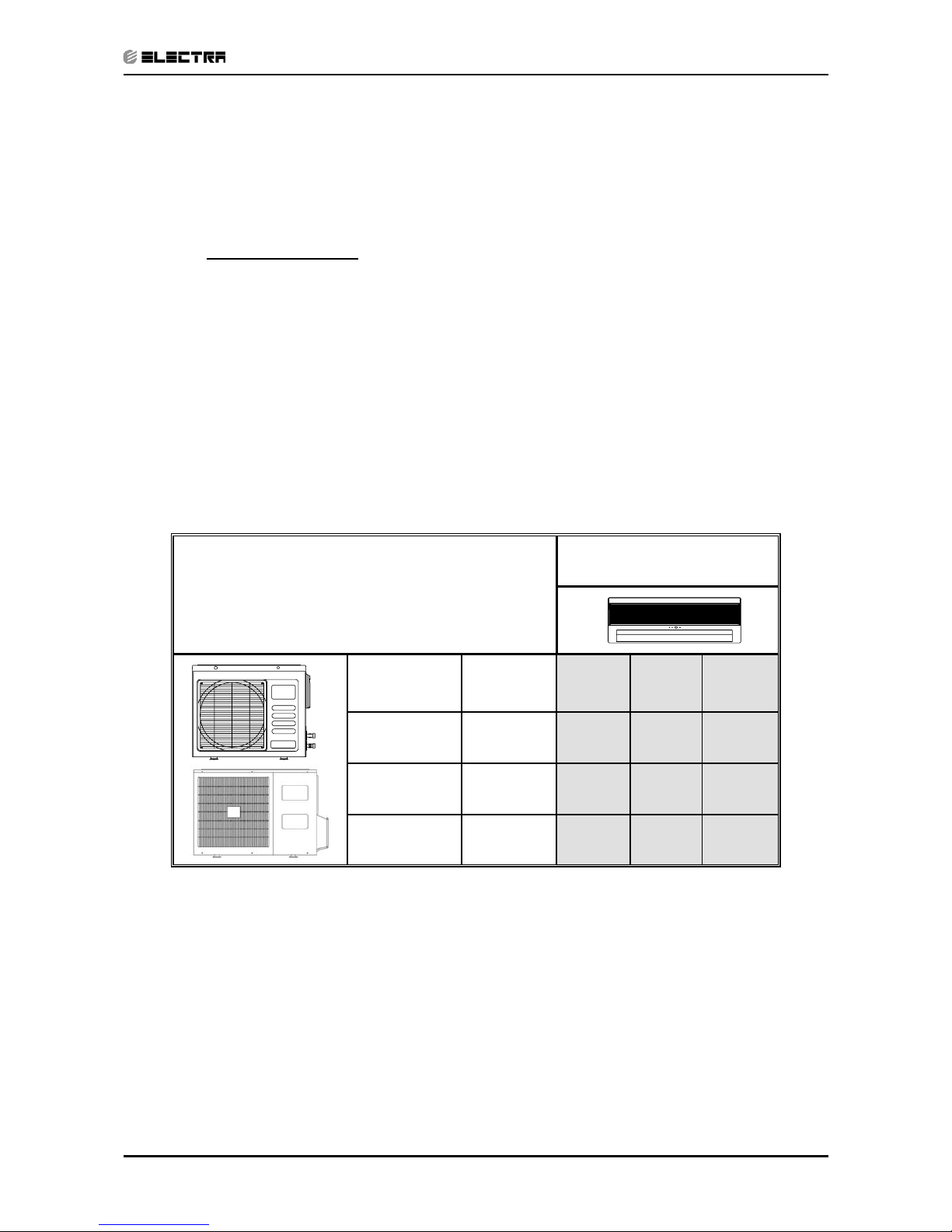
1.10 Matching Table
1.10.1 R410A
OUTDOOR UNITS
INDOOR UNITS
MODEL REFRIGER. Alpha 7 Alpha 9 Alpha 12
CON 7 (Alpha) R410A √
GCN 9 (Alpha) R410A √
GCN 12 (Alpha) R410A √
Page 7
2-1
PRODUCT DATA SHEET
Revision Y05-01Service Manual - ALPHA
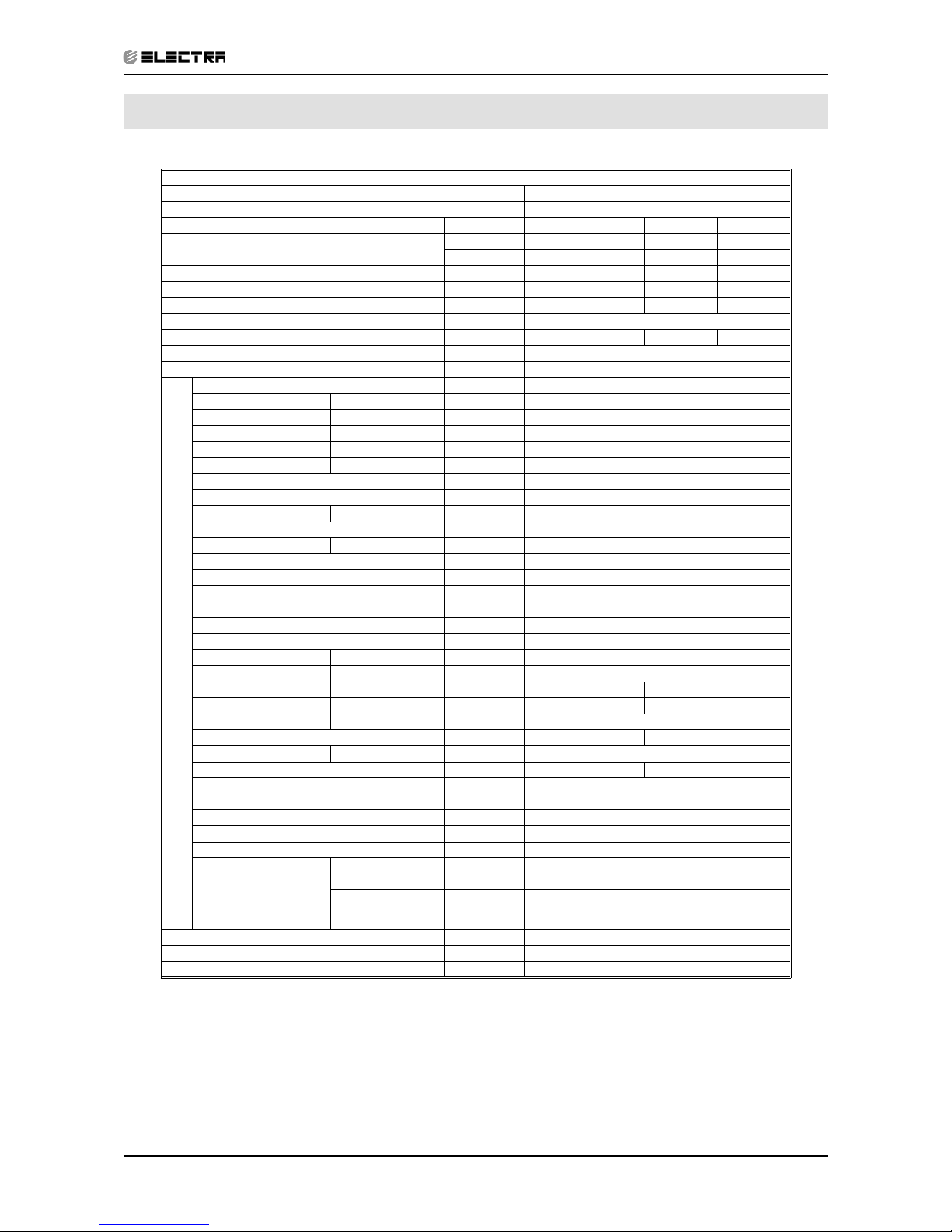
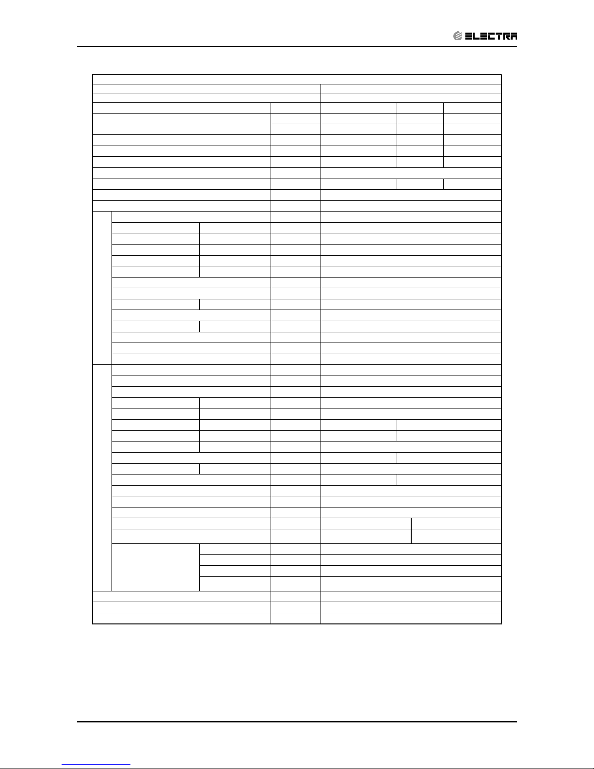
2. PRODUCT DATA SHEET
2.1 R410A
Model Indoor Unit Alpha 7
Model Outdoor Unit CON 7 (Alpha)
Installation Method of Pipe Flared
Characteristics Units Cooling Only Cooling Heating
Capacity
(1)
Btu/hr 7000 7000 7300
kW 2.05 2.05 2.15
Power input
(1)
kW 0.68 0.68 0.63
EER (Cooling) or COP(Heating)
(1)
W/W 3.01 3.01 3.41
Energy efficiency class
B
BB
Power supply V/Ph/Hz 230V/Single/50Hz
Rated current A 3.0 3.0 2.8
Starting current A 15
Circuit breaker rating A 10
INDOOR
Fan type & quantity Crossflow x 1
Fan speeds H/M/L RPM 1150/950
Air flow
(2)
H/M/L m3/hr 390/320
External static pressure Min-Max Pa 0
Sound power level
(3)
H/M/L dB(A) 50/44
Sound pressure level
(4)
H/M/L dB(A) 37/32
Moisture removal l/hr 0.8
Condenstate drain tube I.D mm 16
Dimensions WxHxD mm 680*250*180
Weight kg 7
Package dimensions WxHxD mm 740*250*310
Packaged weight kg 9.5
Units per pallet units 36
Stacking height units 9 levels
OUTDOOR
Refrigerant control Capillary tube
Compressor type, model Rotary,TOSHIBA,PA82X1C-4DZDE
Fan type & quantity Propeller(direct) x 1
Fan speeds H/L RPM 850
Air flow H/L m3/hr 1200
Sound power level H/L dB(A) 61 62
Sound pressure level
(4)
H/L dB(A) 52 53
Dimensions WxHxD mm 610*235*490
Weight kg 27 27.5
Package dimensions WxHxD mm 720*550*360
Packaged weight kg 30/33.5(with kit) 30.5/34(with kit)
Units per pallet Units 12
Stacking height units 4 levels
Refrigerant type R410A
Refrigerant chargless distance Kg/m 0.72kg/7.5m
Additional charge kg 4m≤length≤10m,0.72kg; 10m<length≤15m,0.8kg
Connections between
units
Liquid line In.(mm) Ф 1/4”(6.35)
Suction line In.(mm) Ф 3/8”(9.53)
Max.tubing length m. Max.15
Max.height
difference
m. Max.7
Operation control type Remote control
Heating elements kW
Others
(1) Rating conditions in accordance with ISO 5151 and ISO 13253 (for ducted units) and EN 14511.
(2) Airflow in ducted units; at nominal external static pressure.
(3) Sound power in ducted units is measured at air discharge.
(4) Sound pressure level measured at 1 meter distance from unit.
Page 8
2-2
PRODUCT DATA SHEET
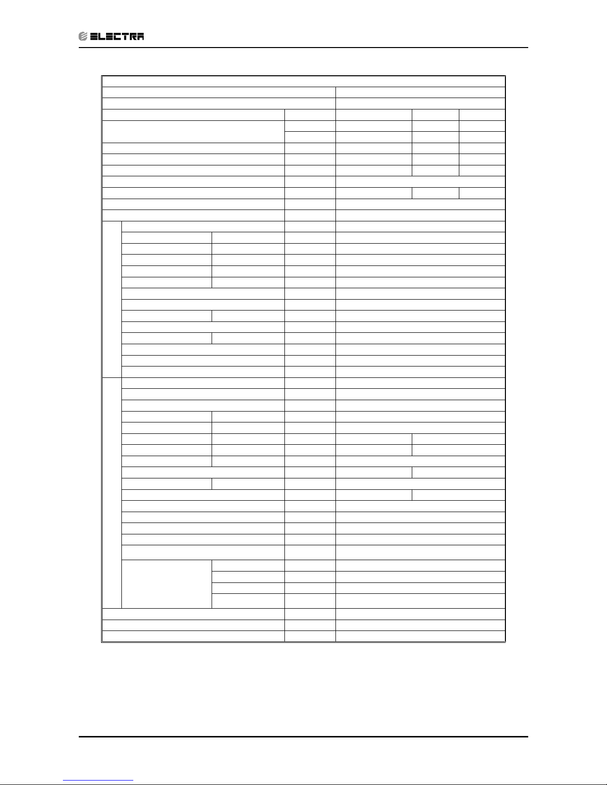
Revision Y05-01 Service Manual - ALPHA
Model Indoor Unit Alpha 9
Model Outdoor Unit GCN 9 (Alpha)
Installation Method of Pipe Flared
Characteristics Units Cooling Only Cooling Heating
Capacity
(1)
Btu/hr
9000 9000 9650
kW
2.64 2.64 2.83
Power input
(1)
kW
0.87 0.87 0.93
EER (Cooling) or COP(Heating)
(1)
W/W
3.03 3.03 3.04
Energy efficiency class
B
BD
Power supply V/Ph/Hz 230V/Single/50Hz
Rated current A 3.9 3.9 4.1
Starting current A 21.7
Circuit breaker rating A 10
INDOOR
Fan type & quantity Crossflow x 1
Fan speeds H/M/L RPM 1310/1100
Air flow
(2)
H/M/L m3/hr 450/360
External static pressure Min-Max Pa 0
Sound power level
(3)
H/M/L dB(A) 53/49
Sound pressure level
(4)
H/M/L dB(A) 41/35
Moisture removal l/hr 1.2
Condenstate drain tube I.D mm 16
Dimensions WxHxD mm 680*250*180
Weight kg 7
Package dimensions WxHxD mm 740*250*310
Packaged weight kg 9.5
Units per pallet units 36
Stacking height units 9 levels
OUTDOOR
Refrigerant control Capillary tube
Compressor type,model
Rotary,TOSHIBA,PA108X1C-4FZDE
Fan type & quantity Propeller(direct) x 1
Fan speeds H/L RPM 750
Air flow H/L m3/hr 1370
Sound power level H/L dB(A) 59 61
Sound pressure level
(4)
H/L dB(A) 49 51
Dimensions WxHxD mm
830x245x545
Weight kg 32.5 33.5
Package dimensions WxHxD mm 880x320x610
Packaged weight kg 35/38.5(with kit) 36/39.5(with kit)
Units per pallet Units 9
Stacking height units 3levels
Refrigerant type R410A
Refrigerant chargless distance kg/m 0.85kg/7.5m 0.9kg/7.5m
Additional charge kg
4m≤length≤10m,0.85kg
10m<length≤15m,0.93kg
4m≤length≤10m,0.9kg
10m<length≤15m,0.98kg
Connections between
units
Liquid line In.(mm) Ф 1/4”(6.35)
Suction line In.(mm) Ф 3/8”(9.53)
Max.tubing length m. Max.15
Max.height
difference
m. Max.7
Operation control type Remote control
Heating elements kW
Others
(1) Rating conditions in accordance with ISO 5151 and ISO 13253 (for ducted units). and EN 14511
(2) Airflow in ducted units; at nominal external static pressure.
(3) Sound power in ducted units is measured at air discharge.
(4) Sound pressure level measured at 1 meter distance from unit.
Page 9
2-3
PRODUCT DATA SHEET
Revision Y05-01Service Manual - ALPHA
Model Indoor Unit Alpha 12
Model Outdoor Unit GCN 12 (Alpha)
Installation Method of Pipe Flared
Characteristics Units Cooling Only Cooling Heating
Capacity
(1)
Btu/hr
12000 12000 12900
kW
3.50 3.50 3.78
Power input
(1)
kW
1.16 1.16 1.17
EER (Cooling) or COP(Heating)
(1)
W/W
3.02 3.02 3.23
Energy efficiency class
B
BC
Power supply V/Ph/Hz 230V/Single/50Hz
Rated current A 5.2 5.2 5.2
Starting current A 31.5
Circuit breaker rating A 10
INDOOR
Fan type & quantity Crossflow x 1
Fan speeds H/M/L RPM 1210/950
Air flow
(2)
H/M/L m3/hr 620/460
External static pressure Min-Max Pa 0
Sound power level
(3)
H/M/L dB(A) 53/47
Sound pressure level
(4)
H/M/L dB(A) 40/33
Moisture removal l/hr 1.5
Condenstate drain tube I.D mm 16
Dimensions WxHxD mm 840*250*180
Weight kg 8
Package dimensions WxHxD mm 900*250*310
Packaged weight kg 11
Units per pallet units 36
Stacking height units 9 levels
OUTDOOR
Refrigerant control Capillary tube
Compressor type,model Rotary,TOSHIBA,PA145X2C-4FT
Fan type & quantity Propeller(direct) x 1
Fan speeds H/L RPM 830
Air flow H/L m3/hr 1450
Sound power level H/L dB(A) 65 65
Sound pressure level
(4)
H/L dB(A) 54 54
Dimensions WxHxD mm 830x245x545
Weight kg 37 38
Package dimensions WxHxD mm 880x320x610
Packaged weight kg 39.5/43(with kit) 40.5/44(with kit)
Units per pallet Units 9
Stacking height units 3 levels
Refrigerant type R410A
Refrigerant chargless distance kg/m 0.89kg/7.5m
Additional charge per 1 meter g/m
4m≤length≤10m,0.89kg
10m<length≤15m,0.97kg
Connections between
units
Liquid line In.(mm) Ф1/4”(6.35)
Suction line In.(mm) ø3/8”(9.53)
Max.tubing length m. Max.15
Max.height
difference
m. Max.7
Operation control type Remote control
Heating elements kW
Others
(1) Rating conditions in accordance with ISO 5151 and ISO 13253 (for ducted units) and EN 14511.
(2) Airflow in ducted units; at nominal external static pressure.
(3) Sound power in ducted units is measured at air discharge.
(4) Sound pressure level measured at 1 meter distance from unit.
Page 10
3-1
RATING CONDITIONS
Revision Y05-01Service Manual - ALPHA
3. RATING CONDITIONS
Standard conditions in accordance with ISO 5151, ISO 13253 (for ducted units)
and EN 14511.
Cooling:
Indoor: 27oC DB 19oC WB
Outdoor: 35 oC DB
Heating:
Indoor: 20oC DB
Outdoor: 7oC DB 6oC WB
3.1 Operating Limits
3.1.1 R410A
Indoor Outdoor
Cooling
Upper limit 32
o
C DB 23oC WB 46oC DB
Lower limit 21oC DB 15oC WB 10oC DB
Heating
Upper limit 27
o
C DB 24oC DB 18oC WB
Lower limit 10
o
C DB -9oC DB -10oC WB
Voltage 198 – 264 V
Page 11
4-1
OUTLINE DIMENSIONS
Revision Y05-01Service Manual - ALPHA
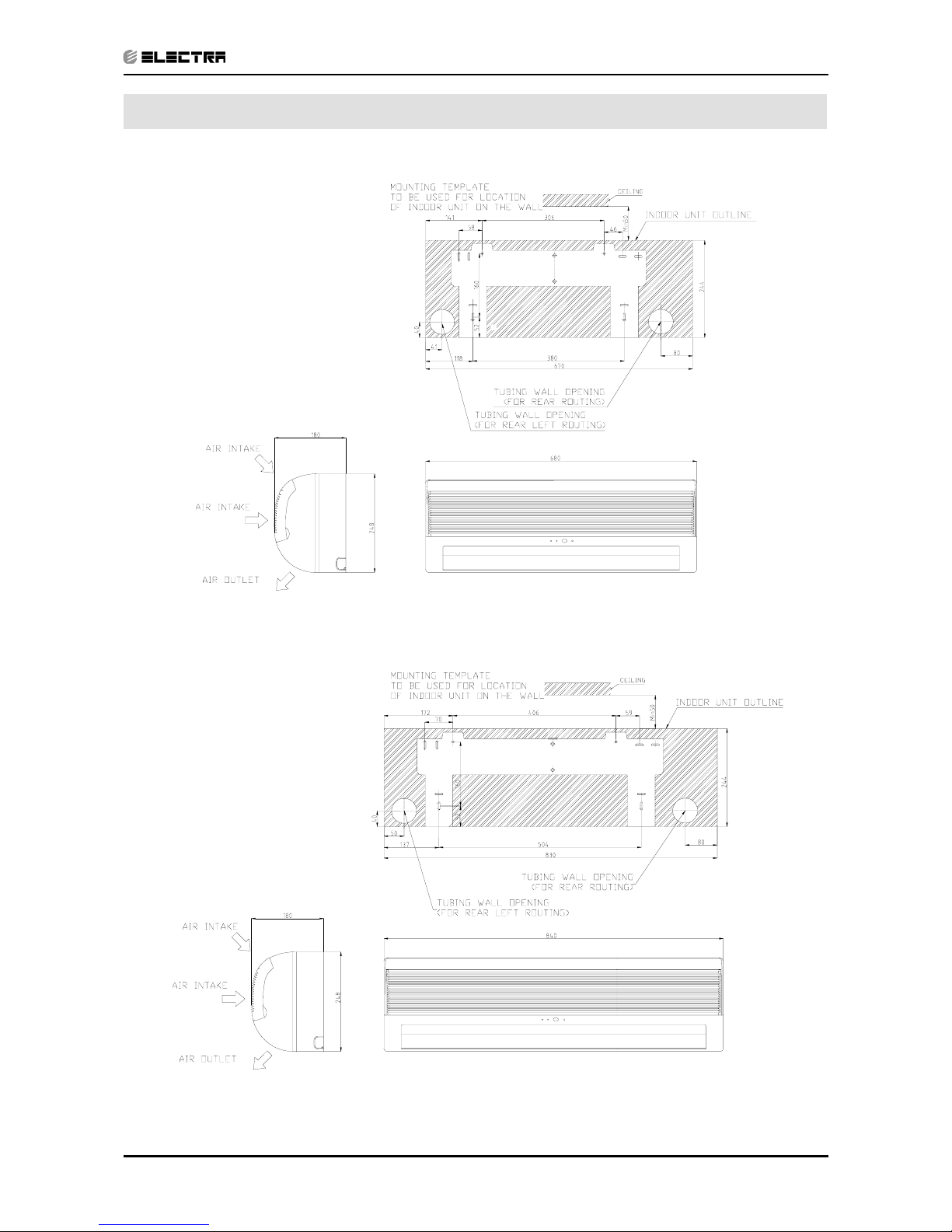
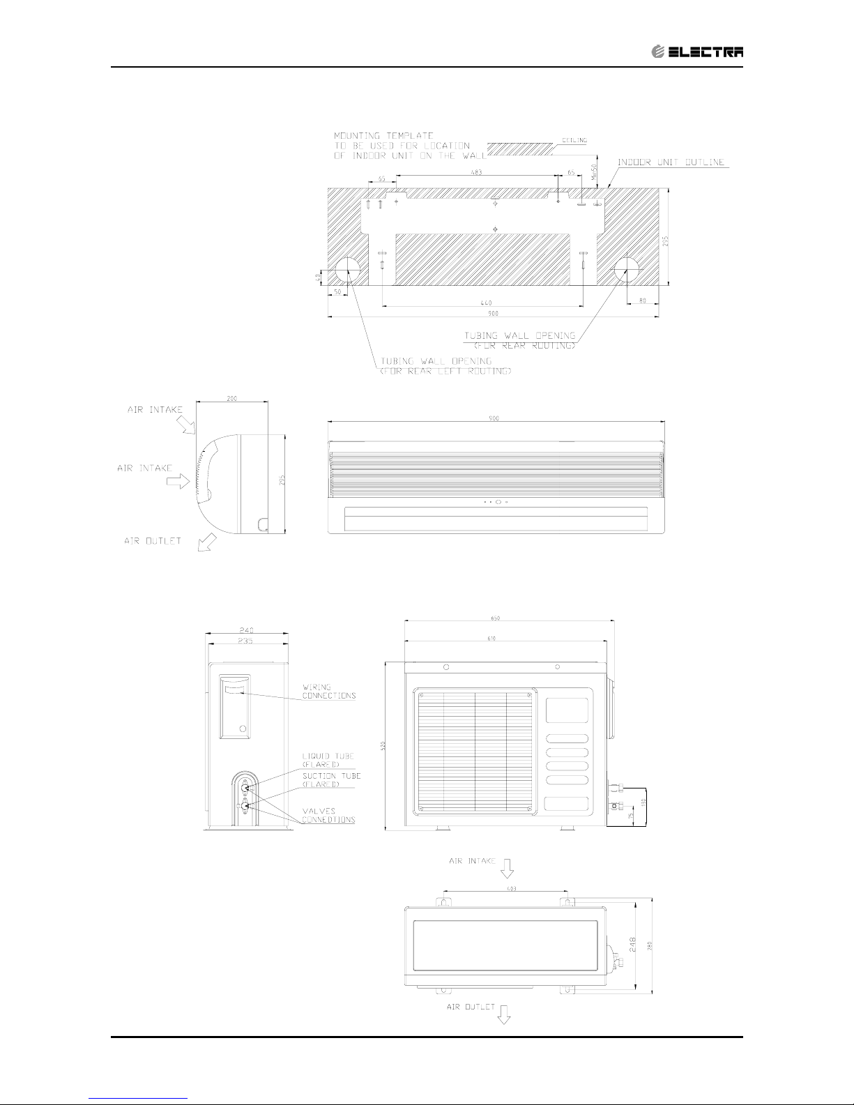
4. OUTLINE DIMENSIONS
4.1 Indoor Unit Apha 7, 9
4.2
Indoor Unit Alpha 12
Page 12
4-2
OUTLINE DIMENSIONS
Revision Y05-01 Service Manual - ALPHA
4.3 Indoor Unit Alpha 17
4.4 Outdoor Unit CON 7 (Alpha)
Page 13
4-3
OUTLINE DIMENSIONS
Revision Y05-01Service Manual - ALPHA
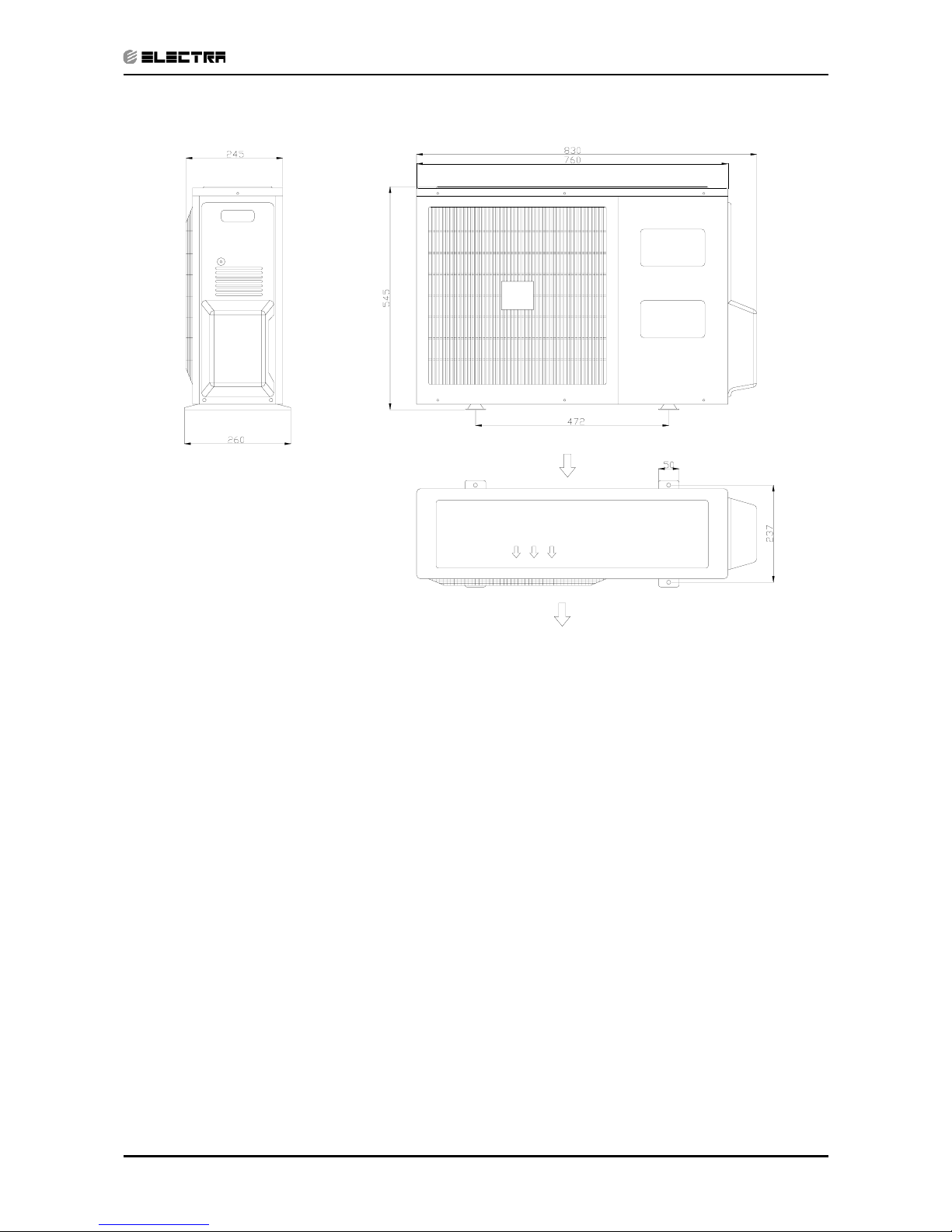
4.5 Outdoor Unit GCN 12 (Alpha)
AI R OUTL ET
AI R I NTAKE
Page 14
5-1
PERFORMANCE DATA & PRESSURE CURVES
Revision Y05-01Service Manual - ALPHA
5. PERFORMANCE DATA & PRESSURE CURVES
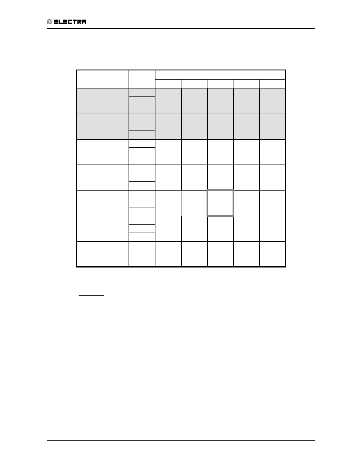
5.1 Alpha7/CON7
5.1.1 Cooling Capacity (kW)
ENTERING AIR
DB OD Coil(
o
C)
Data
ENTERING AIR WB/DB ID Coil(
o
C)
15/21 17/24 19/27 21/29 23/32
15
(1)
TC
2.09 2.21 2.32 2.42 2.50
SC 1.47 1.56 1.64 1.60 1.63
PI
0.48 0.48 0.48 0.49 0.49
20
(1)
TC
2.07 2.19 2.30 2.40 2.48
SC 1.48 1.57 1.66 1.61 1.64
PI
0.52 0.52 0.53 0.53 0.53
25
TC
1.99 2.13 2.26 2.36 2.44
SC 1.43 1.53 1.62 1.59 1.63
PI
0.56 0.57 0.57 0.58 0.58
30
TC
1.87 2.01 2.17 2.26 2.34
SC 1.36 1.47 1.58 1.55 1.61
PI
0.61 0.62
0.62
0.63 0.63
35
TC
1.72 1.87
2.05
2.15 2.23
SC 1.28 1.39 1.52 1.50 1.56
PI
0.66 0.67
0.68
0.69 0.69
40
TC
1.56 1.70
1.89
1.99 2.07
SC 1.19 1.31 1.44 1.42 1.48
PI
0.71 0.72 0.73 0.74 0.75
46
TC
1.35 1.50 1.68 1.78 1.87
SC 1.08 1.20 1.35 1.32 1.39
PI
0.78 0.79 0.81 0.82 0.82
LEGEND
TC – Total Cooling Capacity, kW
SC – Sensible Capacity, kW
PI – Power Input, kW
WB – Wet Bulb Temp., (
o
C)
DB – Dry Bulb Temp., (
o
C)
ID – Indoor
OD – Outdoor
(1) Marked area is below standard operating limits. For operating in low ambient
conditions, an A.S.K Kit is required.
Page 15
5-2
PERFORMANCE DATA & PRESSURE CURVES
Revision Y05-01 Service Manual - ALPHA
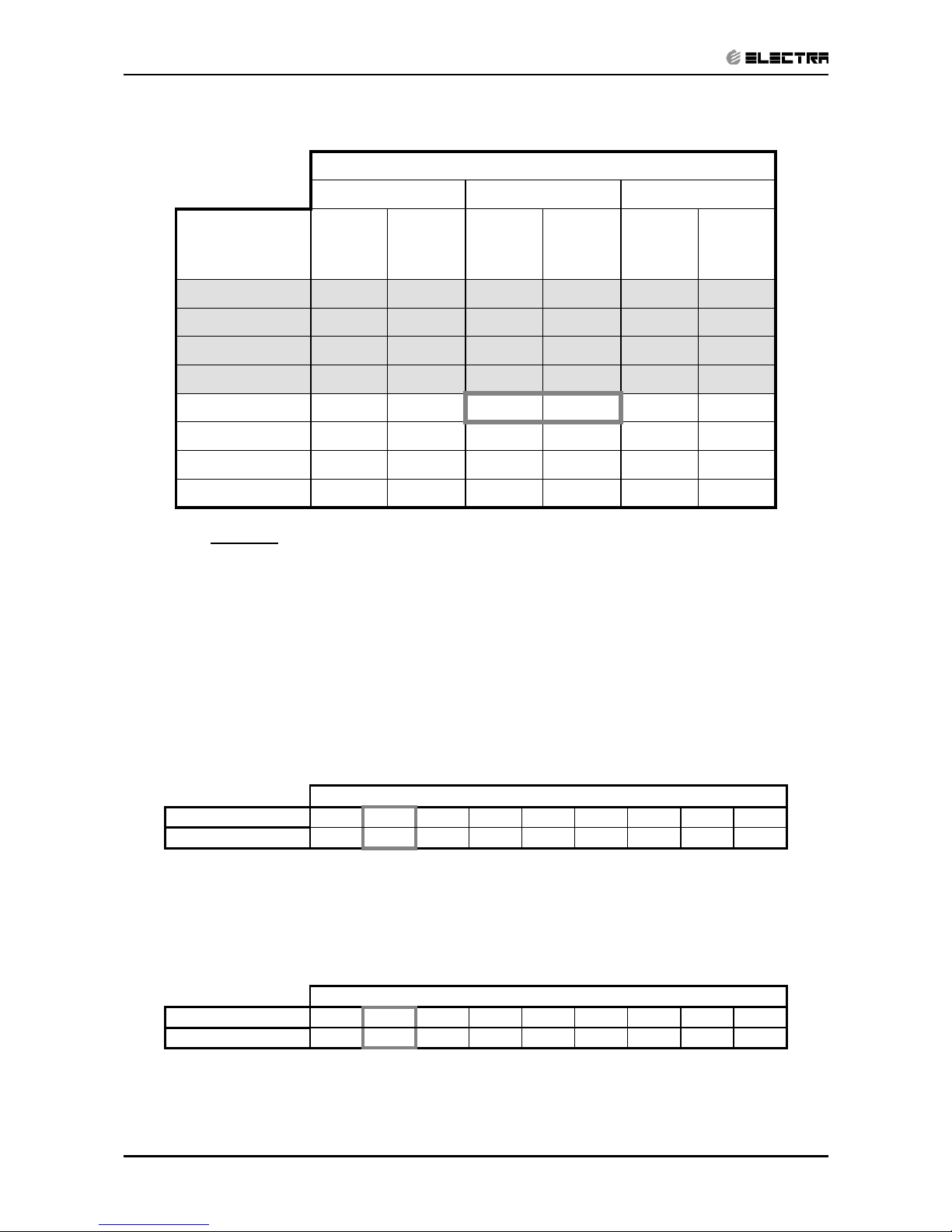
5.1.2 Heating
ENTERING AIR DB ID COIL(Oc)
15 20 25
ENTERING
WB OD
COIL(
o
C)
TH Pl TH Pl TH Pl
-10 1.13 0.50 1.09 0.54 1.04 0.56
-7 1.21 0.52 1.17 0.54 1.13 0.57
-2 1.29 0.52 1.25 0.55 1.20 0.59
2 1.57 0.55
1.51 0.58
1.44 0.62
6 2.21 0.59 2.15 0.63 2.07 0.67
10 2.41 0.62
2.34 0.66
2.28 0.71
15 2.60 0.65 2.54 0.70 2.47 0.74
20 2.74 0.67 2.68 0.72 2.60 0.78
LEGEND
TH – Total Heating Capacity, kW
PI – Power Input, kW
WB – Wet Bulb Temp., (
o
C)
DB – Dry Bulb Temp., (
o
C)
ID – Indoor
OD – Outdoor
Page 16

5-3
PERFORMANCE DATA & PRESSURE CURVES
Revision Y05-01Service Manual - ALPHA
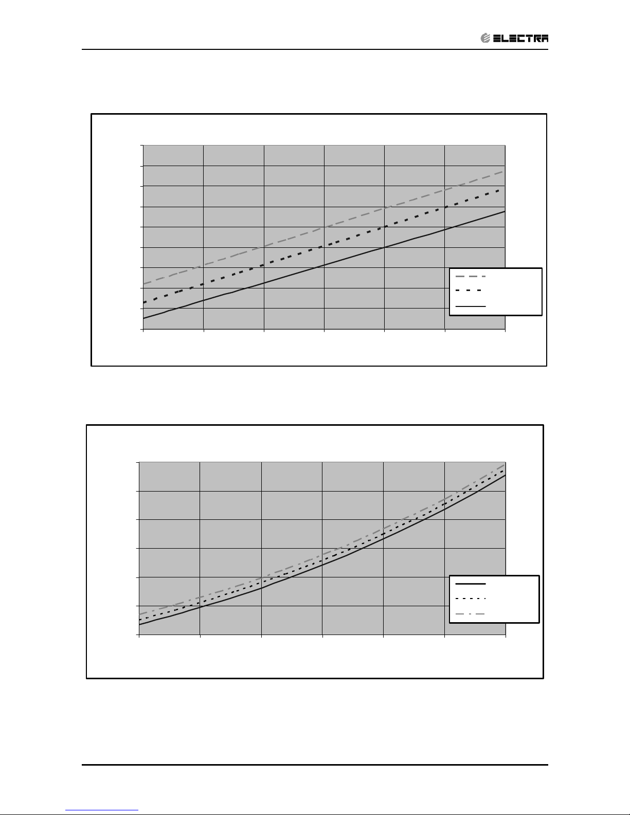
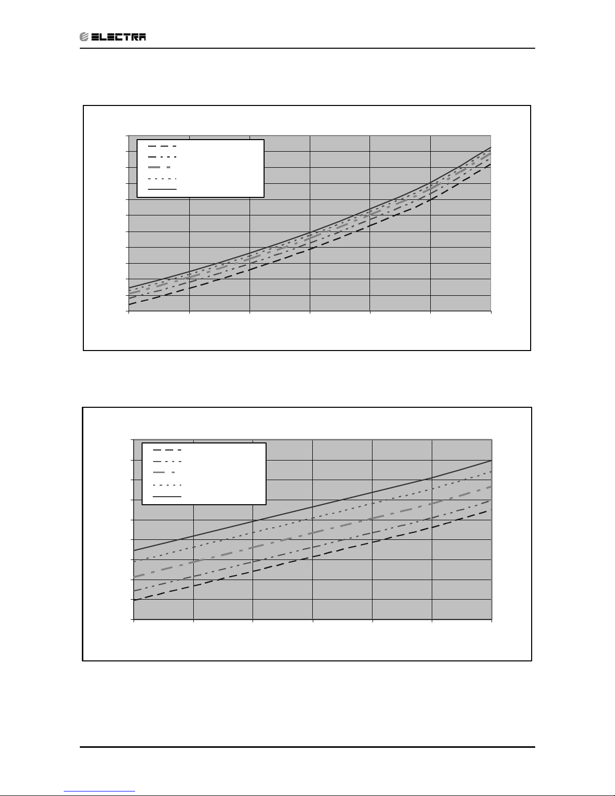
5.2 Model: Alpha7/CON7
5.2.1 Cooling
Discharge Pressure VS.Outdoor Temp
16
18
20
22
24
26
28
30
32
34
36
38
15 20 25 30 35 40 46
Outdoor Temp.(DB oC )
Discharge Pressure (Bar[g])
15/21(WB/DB ºC)
17/24(WB/DB ºC)
19/27(WB/DB ºC)
21/29(WB/DB ºC)
23/32(WB/DB ºC)
Suction Pressure VS.Outdoor Temp
6.5
7.0
7.5
8.0
8.5
9.0
9.5
10.0
10.5
11.0
15 20 25 30 35 40 46
Outdoor Temp.(DB oC )
Suction Pressure (Bar[g])
15/21(WB/DB ºC)
17/24(WB/DB ºC)
19/27(WB/DB ºC)
21/29(WB/DB ºC)
23/32(WB/DB ºC)
Page 17
5-4
PERFORMANCE DATA & PRESSURE CURVES
Revision Y05-01 Service Manual - ALPHA
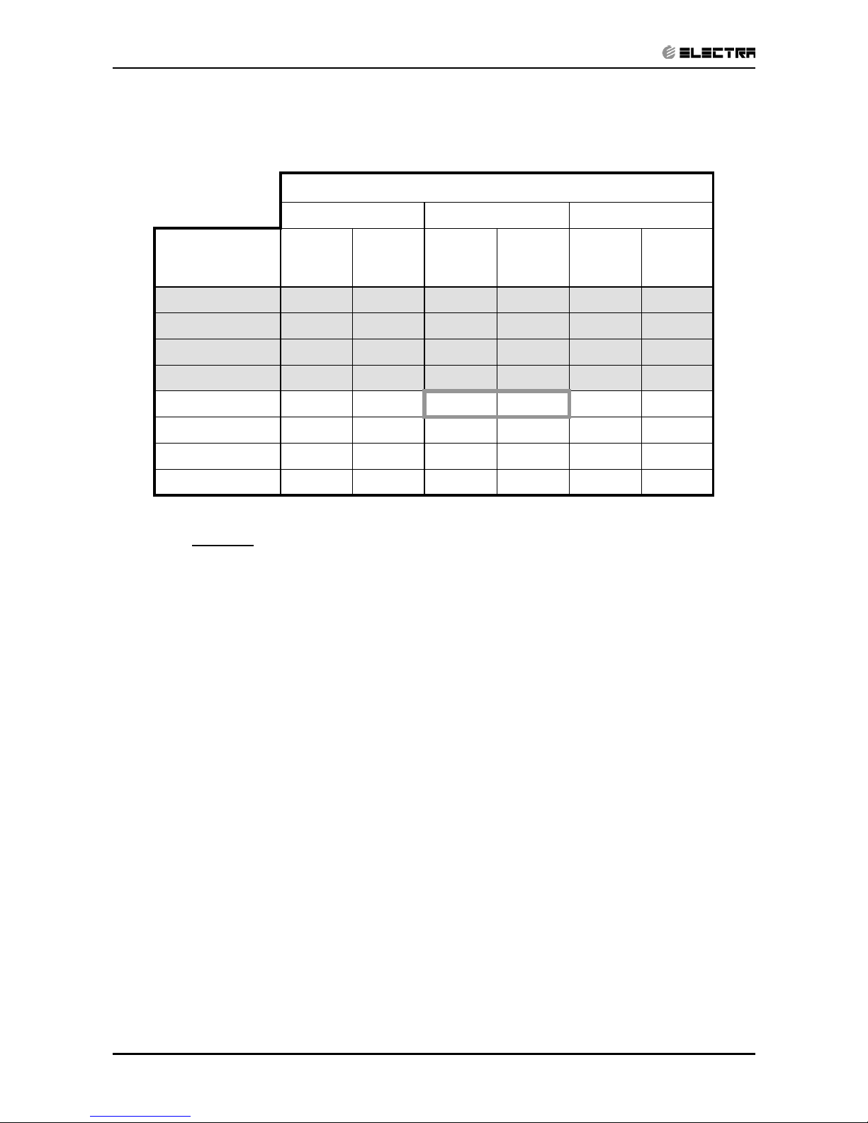
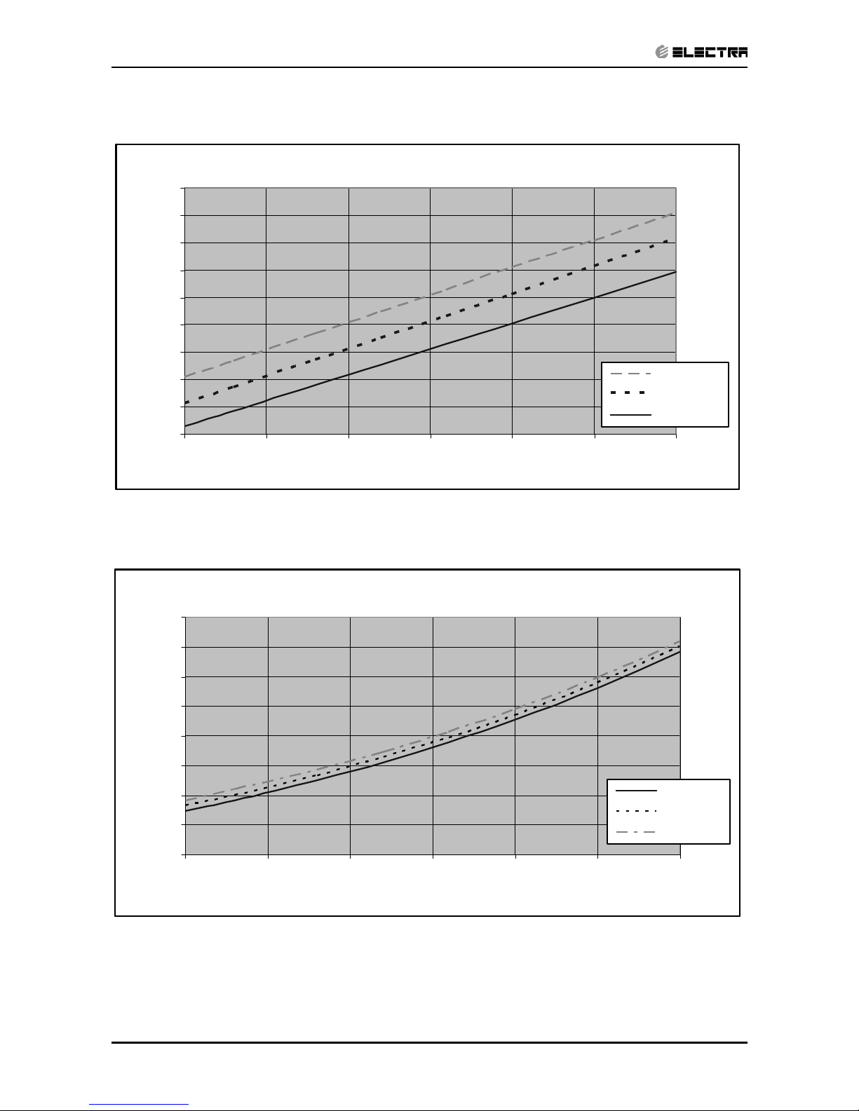
5.2.2 Heating
Discharge Pressure VS.Outdoor Temp
18
20
22
24
26
28
30
32
34
36
-10 -5 0 5 10 15 20
Outdoor Temp.( WB oC )
Discharge Pressure(Bar[g])
25 DB (ºC)
20 DB (ºC)
15 DB (ºC)
Suction Pressure VS.Outdoor Temp
4.0
5.0
6.0
7.0
8.0
9.0
10.0
-10 -5 0 5 10 15 20
Outdoor Temp.( WB oC )
Suction Pressure(Bar[g])
15 DB (ºC)
20 DB (ºC)
25 DB (ºC)
Page 18

5-5
PERFORMANCE DATA & PRESSURE CURVES
Revision Y05-01Service Manual - ALPHA
5.3 Alpha9/GCN9
5.3.1 Cooling Capacity (kW)
ENTERING AIR
DB OD Coil(
o
C)
Data
ENTERING AIR WB/DB ID Coil(
o
C)
15/21 17/24 19/27 21/29 23/32
15
(1)
TC
2.69 2.85 2.98 3.12 3.22
SC 1.76 1.87 1.97 1.92 1.95
PI
0.62 0.62 0.62 0.62 0.62
20
(1)
TC
2.67 2.82 2.96 3.09 3.19
SC 1.90 2.02 2.13 2.07 2.12
PI
0.67 0.67 0.67 0.68 0.68
25
TC
2.56 2.75 2.90 3.04 3.14
SC 1.71 1.83 1.94 1.90 1.95
PI
0.72 0.73 0.73 0.74 0.74
30
TC
2.40 2.59 2.80 2.90 3.01
SC 1.63 1.76 1.90 1.86 1.93
PI
0.78 0.79
0.80
0.81 0.81
35
TC
2.22 2.40
2.64
2.77 2.88
SC 1.53 1.67 1.82 1.80 1.87
PI
0.84 0.86
0.87
0.88 0.88
40
TC
2.01 2.19
2.43
2.56 2.67
SC 1.42 1.57 1.72 1.69 1.78
PI
0.91 0.92 0.94 0.95 0.96
46
TC
1.74 1.93 2.16 2.30 2.40
SC 1.29 1.43 1.61 1.58 1.66
PI
1.00 1.01 1.03 1.04 1.05
LEGEND
TC – Total Cooling Capacity, kW
SC – Sensible Capacity, kW
PI – Power Input, kW
WB – Wet Bulb Temp., (
o
C)
DB – Dry Bulb Temp., (oC)
ID – Indoor
OD – Outdoor
(1) Marked area is below standard operating limits. For operating in low ambient
conditions, an A.S.K Kit is required.
Page 19
5-6
PERFORMANCE DATA & PRESSURE CURVES
Revision Y05-01 Service Manual - ALPHA
5.3.2 Heating
ENTERING AIR DB ID COIL(Oc)
15 20 25
ENTERING
WB OD
COIL(
o
C)
TH Pl TH Pl TH Pl
-10 1.49 0.74 1.43 0.79 1.37 0.83
-7 1.60 0.76 1.54 0.80 1.49 0.85
-2 1.70 0.77 1.64 0.82 1.58 0.86
2 2.07 0.81
1.98 0.86
1.90 0.91
6 2.91 0.87 2.83 0.93 2.73 0.99
10 3.17 0.92
3.08 0.98
3.00 1.05
15 3.42 0.96 3.34 1.03 3.25 1.10
20 3.61 0.99 3.52 1.07 3.42 1.15
LEGEND
TH – Total Heating Capacity, kW
PI – Power Input, kW
WB – Wet Bulb Temp., (
o
C)
DB – Dry Bulb Temp., (
o
C)
ID – Indoor
OD – Outdoor
Page 20
5-7
PERFORMANCE DATA & PRESSURE CURVES
Revision Y05-01Service Manual - ALPHA
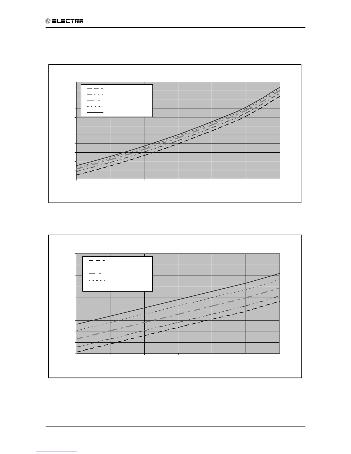
5.4 Model: Alpha9/GCN9
5.4.1 Cooling
Discharge Pressure VS.Outdoor Temp
16
18
20
22
24
26
28
30
32
34
36
38
15 20 25 30 35 40 46
Outdoor Temp.(DB oC )
Discharge Pressure (Bar[g])
15/21(WB/DB ºC)
17/24(WB/DB ºC)
19/27(WB/DB ºC)
21/29(WB/DB ºC)
23/32(WB/DB ºC)
Suction Pressure VS.Outdoor Temp
6.5
7.0
7.5
8.0
8.5
9.0
9.5
10.0
10.5
11.0
15 20 25 30 35 40 46
Outdoor Temp.(DB oC )
Suction Pressure (Bar[g])
15/21(WB/DB ºC)
17/24(WB/DB ºC)
19/27(WB/DB ºC)
21/29(WB/DB ºC)
23/32(WB/DB ºC)
Page 21
5-8
PERFORMANCE DATA & PRESSURE CURVES
Revision Y05-01 Service Manual - ALPHA
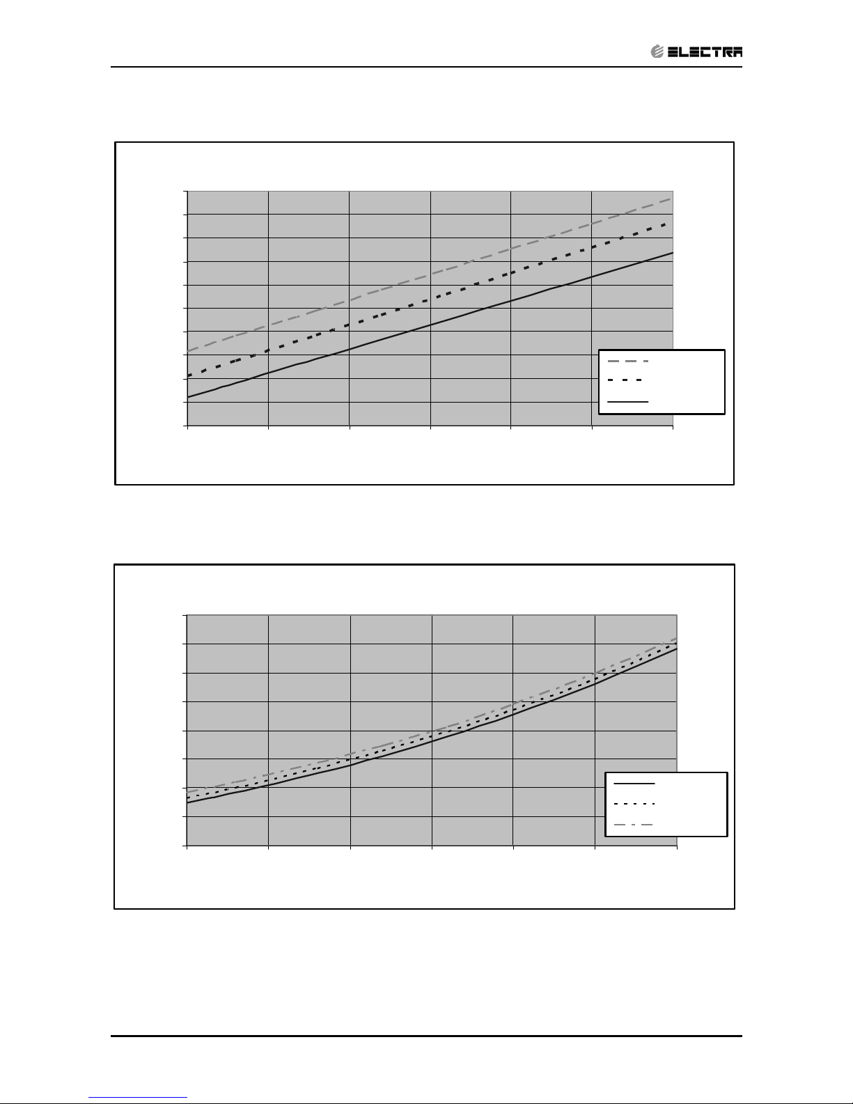
5.4.2 Heating
Discharge Pressure VS.Outdoor Temp
20
22
24
26
28
30
32
34
36
38
40
-10 -5 0 5 10 15 20
Outdoor Temp.( WB oC )
Discharge Pressure(Bar[g])
25 DB (ºC)
20 DB (ºC)
15 DB (ºC)
Suction Pressure VS.Outdoor Temp
3.0
4.0
5.0
6.0
7.0
8.0
9.0
10.0
11.0
-10 -5 0 5 10 15 20
Outdoor Temp.( WB oC )
Suction Pressure(Bar[g])
15 DB (ºC)
20 DB (ºC)
25 DB (ºC)
Page 22
5-9
PERFORMANCE DATA & PRESSURE CURVES
Revision Y05-01Service Manual - ALPHA
5.5 Alpha12/GCN12
5.5.1 Cooling Capacity (kW)
ENTERING AIR
DB OD Coil(
o
C)
Data
ENTERING AIR WB/DB ID Coil(
o
C)
15/21 17/24 19/27 21/29 23/32
15
(1)
TC
3.57 3.78 3.96 4.13 4.27
SC 2.39 2.53 2.67 2.61 2.65
PI
0.82 0.82 0.83 0.83 0.83
20
(1)
TC
3.54 3.75 3.92 4.10 4.24
SC 2.52 2.68 2.83 2.75 2.81
PI
0.89 0.89 0.90 0.90 0.91
25
TC
3.40 3.64 3.85 4.03 4.17
SC 2.32 2.49 2.63 2.58 2.65
PI
0.96 0.97 0.98 0.98 0.99
30
TC
3.19 3.43 3.71 3.85 3.99
SC 2.21 2.38 2.57 2.52 2.62
PI
1.04 1.05
1.07
1.07 1.08
35
TC
2.94 3.19
3.50
3.68 3.82
SC 2.08 2.26 2.47 2.44 2.54
PI
1.12 1.14
1.16
1.17 1.17
40
TC
2.66 2.91
3.22
3.40 3.54
SC 1.93 2.12 2.34 2.30 2.41
PI
1.21 1.23 1.25 1.26 1.27
46
TC
2.31 2.56 2.87 3.05 3.19
SC 1.75 1.95 2.19 2.15 2.25
PI
1.33 1.35 1.37 1.39 1.41
LEGEND
TC – Total Cooling Capacity, kW
SC – Sensible Capacity, kW
PI – Power Input, kW
WB – Wet Bulb Temp., (
o
C)
DB – Dry Bulb Temp., (
o
C)
ID – Indoor
OD – Outdoor
(1) Marked area is below standard operating limits. For operating in low ambient
conditions, an A.S.K Kit is required
Page 23
5-10
PERFORMANCE DATA & PRESSURE CURVES
Revision Y05-01 Service Manual - ALPHA
5.5.2 Heating
ENTERING AIR DB ID COIL(Oc)
15 20 25
ENTERING
WB OD
COIL(
o
C)
TH Pl TH Pl TH Pl
-10 1.98 0.94 1.91 1.00 1.83 1.05
-7 2.14 0.96 2.06 1.01 1.98 1.07
-2 2.27 0.97 2.19 1.03 2.12 1.09
2 2.76 1.02
2.65 1.08
2.53 1.15
6 3.89 1.09 3.78 1.17 3.65 1.24
10 4.23 1.15
4.12 1.23
4.01 1.32
15 4.57 1.21 4.46 1.30 4.35 1.38
20 4.82 1.24 4.71 1.35 4.57 1.45
LEGEND
TH – Total Heating Capacity, kW
PI – Power Input, kW
WB – Wet Bulb Temp., (
o
C)
DB – Dry Bulb Temp., (
o
C)
ID – Indoor
OD – Outdoor
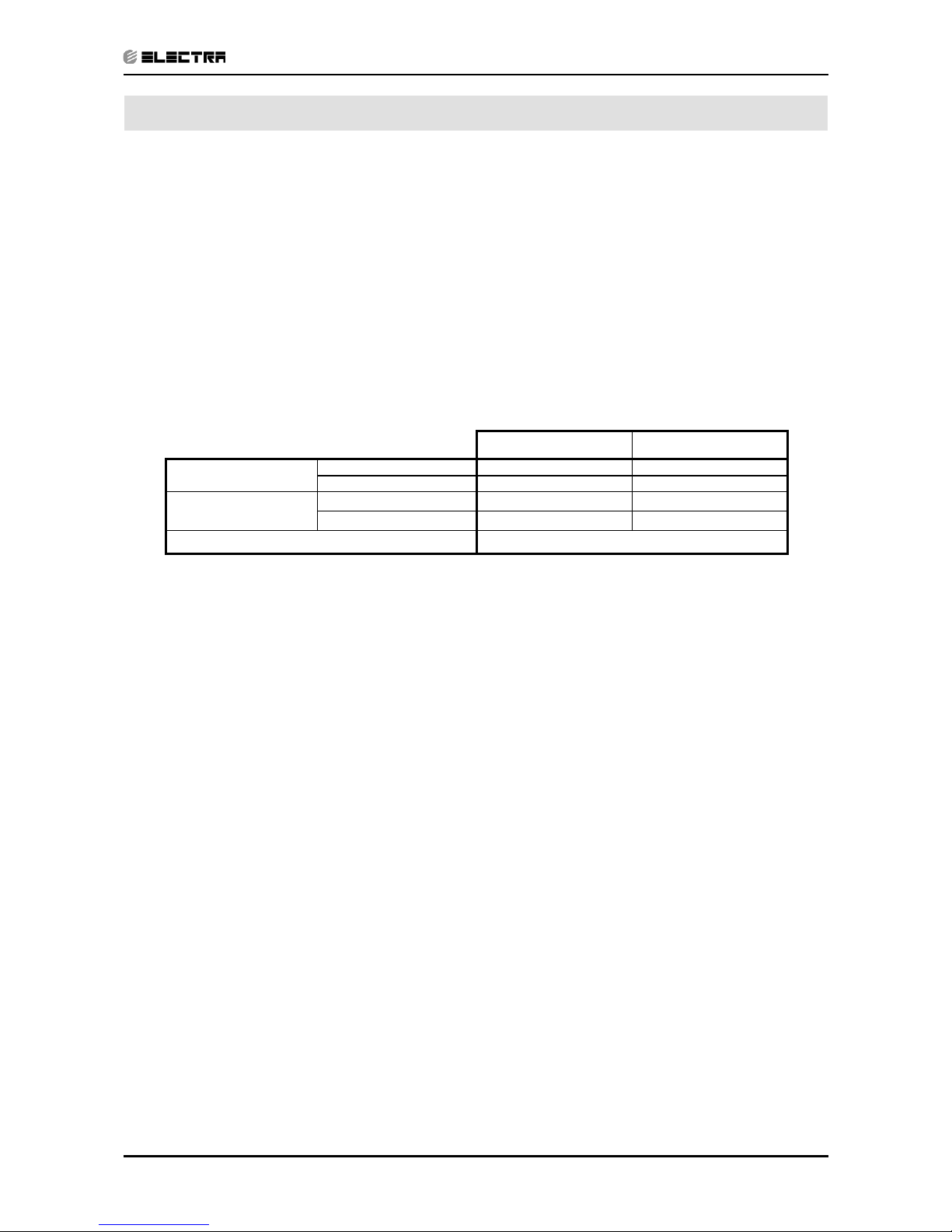
5.6 Capacity Correction Factor Due to Tubing Length
5.6.1 Cooling
TOTAL TUBING LENGTH (One Way)
Model
3m
7.5m
10m 15m 20m 25m 30m 40m 50m
Alpha7,9,12
1.02
1
0.97 0.95 --- --- --- --- ---
* Minimum recommended tubing length between indoor and outdoor units is 3m.
5.6.2 Heating
TOTAL TUBING LENGTH(One Way)
Model
3m
7.5m
10m 15m 20m 25m 30m 40m 50m
Alpha7,9,12
1.03
1
0.98 0.96 --- --- --- --- ---
* Minimum recommended tubing length between indoor and outdoor units is 3m.
Page 24
5-11
PERFORMANCE DATA & PRESSURE CURVES
Revision Y05-01Service Manual - ALPHA
5.7 Model: Alpha12/GCN12
5.7.1 Cooling
Discharge Pressure VS.Outdoor Temp
16
18
20
22
24
26
28
30
32
34
36
38
15 20 25 30 35 40 46
Outdoor Temp.(DB oC )
Discharge Pressure (Bar[g])
15/21(W B/DB ºC)
17/24(W B/DB ºC)
19/27(WB/DB ºC)
21/29(W B/DB ºC)
23/32(W B/DB ºC)
Suction Pressure VS.Outdoor Temp
6.0
6.5
7.0
7.5
8.0
8.5
9.0
9.5
10.0
10.5
15 20 25 30 35 40 46
Outdoor Temp.(DB oC )
Suction Pressure (Bar[g])
15/21(WB/DB ºC)
17/24(WB/DB ºC)
19/27(WB/DB ºC)
21/29(WB/DB ºC)
23/32(WB/DB ºC)
Page 25
5-12
PERFORMANCE DATA & PRESSURE CURVES
Revision Y05-01 Service Manual - ALPHA
5.7.2 Heating
Discharge Pressure VS.Outdoor Temp
20
22
24
26
28
30
32
34
36
38
-10 -5 0 5 10 15 20
Outdoor Temp.( WB oC )
Discharge Pressure(Bar[g])
25 DB (ºC)
20 DB (ºC)
15 DB (ºC)
Suction Pressure VS.Outdoor Temp
3.0
4.0
5.0
6.0
7.0
8.0
9.0
10.0
11.0
-10 -5 0 5 10 15 20
Outdoor Temp.( WB oC )
Suction Pressure(Bar[g])
15 DB (ºC)
20 DB (ºC)
25 DB (ºC)
Page 26
6-1
SOUND LEVEL CHARACTERISTICS
Revision Y05-01Service Manual - ALPHA
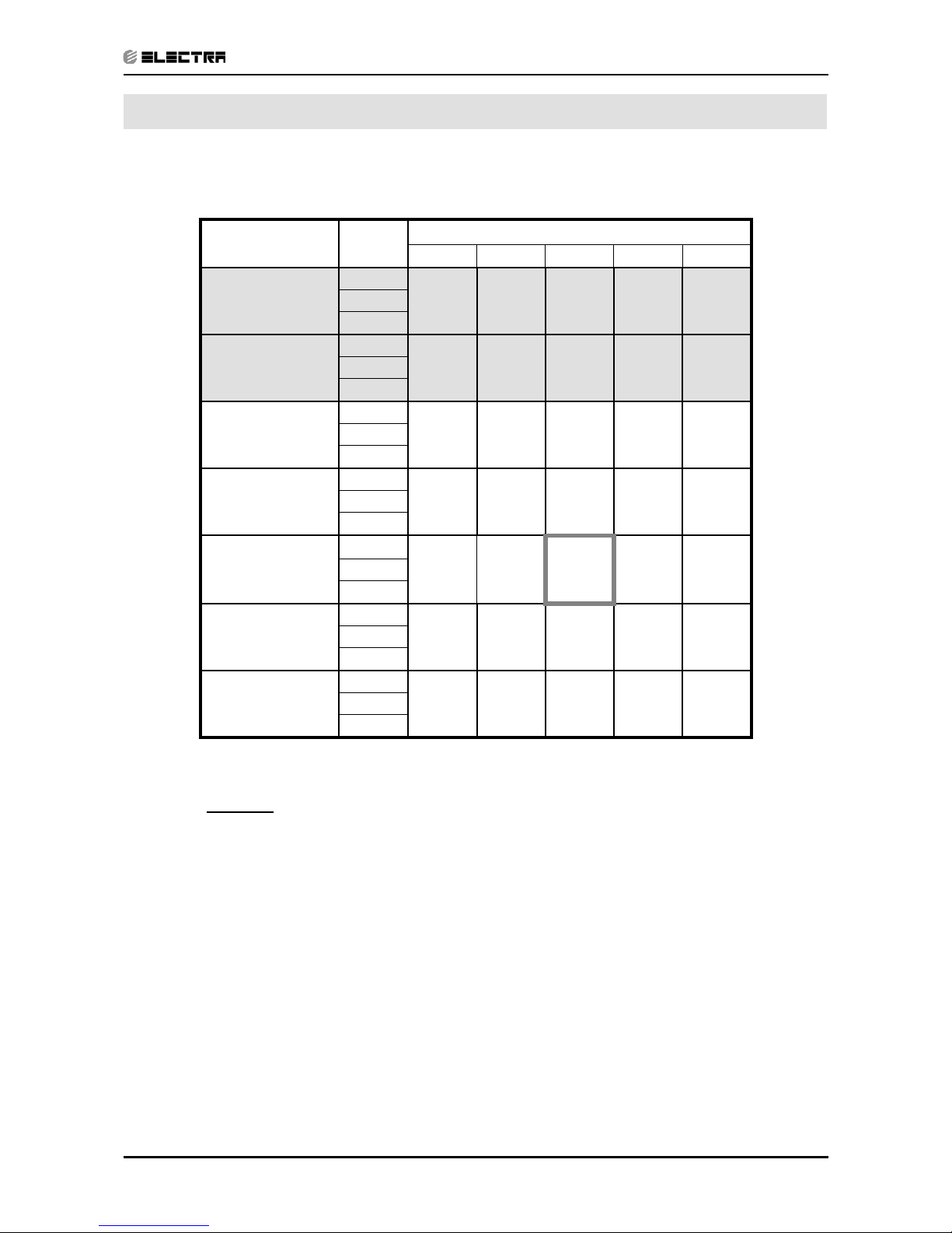
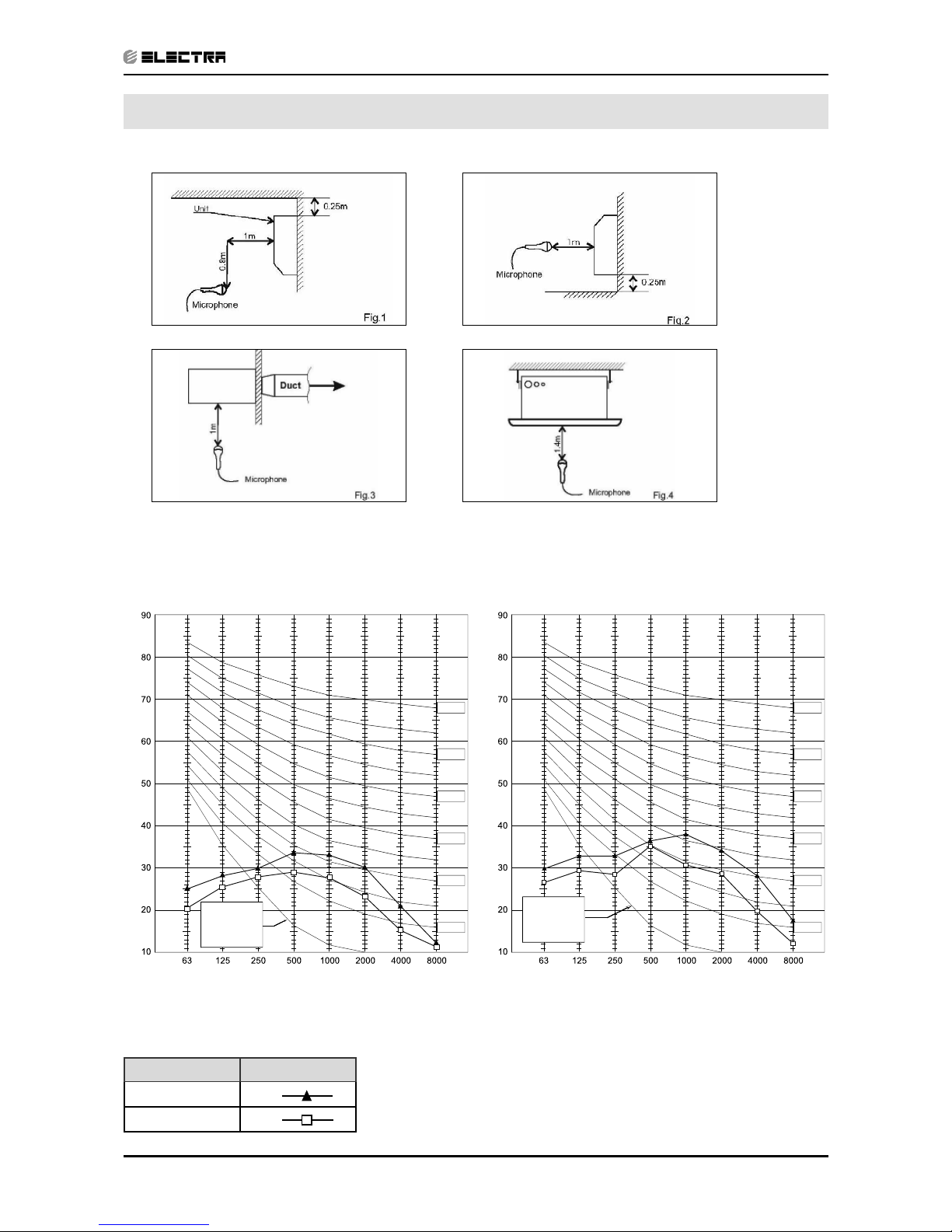
6. SOUND LEVEL CHARACTERISTICS
6.1 Sound Pressure Level
Figure 1. Wall Mounted Figure 2. Floor Mounted
Figure 3. Ducted Figure 4. Cassette
6.2 Soud Pressure Level Spectrum (Measured as Figure 1)
Alpha 7 Alpha 9
BAND CENTER FREQUENCIES, Hz
APPROXIMATE
THRESHOLD OF
HEARING FOR
CONTINUOUS
NOISE
NC-70
NC-60
NC-50
NC-40
NC-30
NC-20
OCTAVE BAND SOUND PRESSURE LEVEL, dB re 0.002 MICRO BAR
FAN SPEED LINE
HI
LO
BAND CENTER FREQUENCIES, Hz
APPROXIMATE
THRESHOLD OF
HEARING FOR
CONTINUOUS
NOISE
NC-70
NC-60
NC-50
NC-40
NC-30
NC-20
OCTAVE BAND SOUND PRESSURE LEVEL, dB re 0.002 MICRO BAR
Page 27
6-2
SOUND LEVEL CHARACTERISTICS
Revision Y05-01 Service Manual - ALPHA
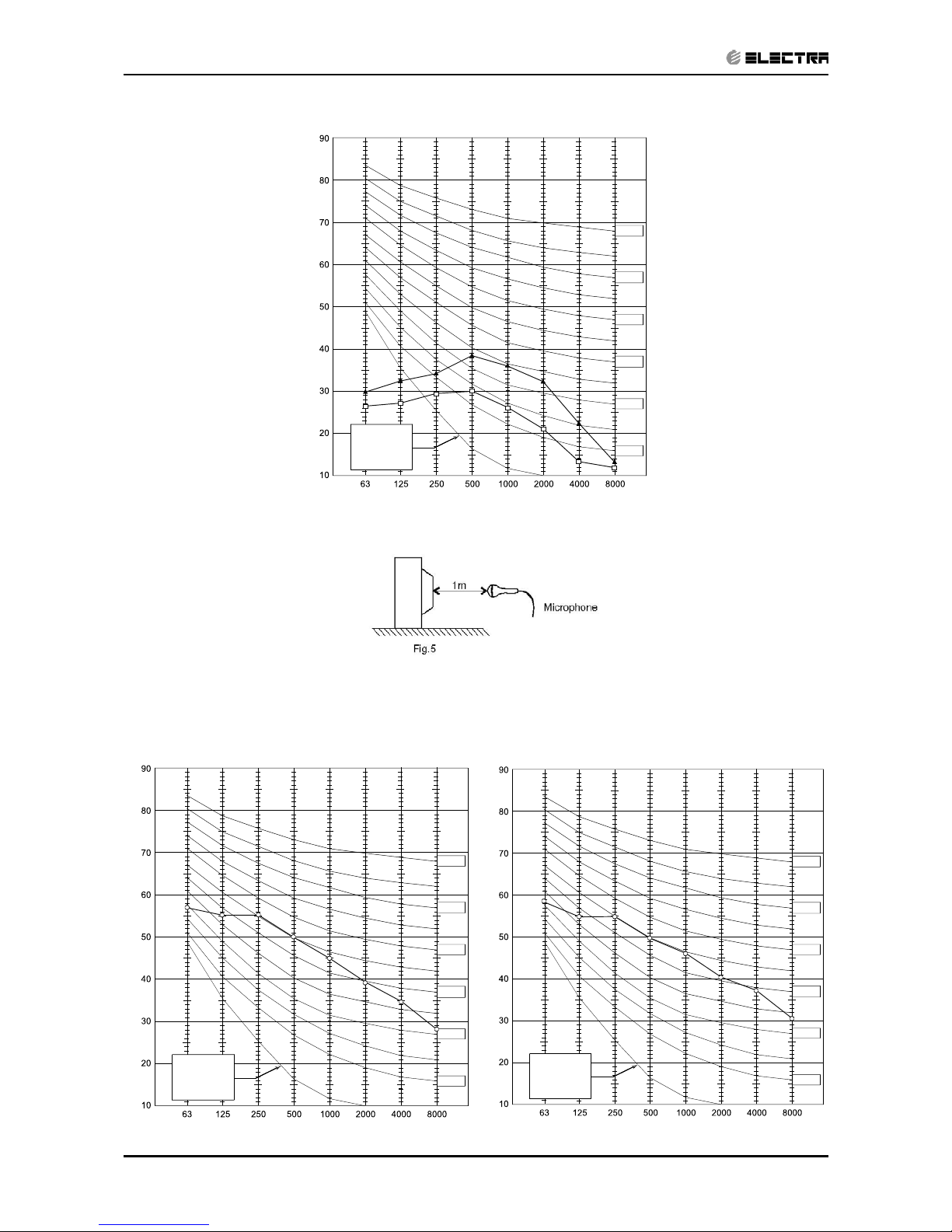
Microphone Distance from Unit
Alpha 12
6.3 Outdoor units
6.4 Sound Pressure Level Spectrum (Measured as Figure 5)
Alpha 7 Cooling Alpha 7 Heating
BAND CENTER FREQUENCIES, Hz
APPROXIMATE
THRESHOLD OF
HEARING FOR
CONTINUOUS
NOISE
NC-70
NC-60
NC-50
NC-40
NC-30
NC-20
OCTAVE BAND SOUND PRESSURE LEVEL, dB re 0.002 MICRO BAR
BAND CENTER FREQUENCIES, Hz
APPROXIMATE
THRESHOLD OF
HEARING FOR
CONTINUOUS
NOISE
NC-70
NC-60
NC-50
NC-40
NC-30
NC-20
OCTAVE BAND SOUND PRESSURE LEVEL, dB re 0.002 MICRO BAR
BAND CENTER FREQUENCIES, Hz
APPROXIMATE
THRESHOLD OF
HEARING FOR
CONTINUOUS
NOISE
NC-70
NC-60
NC-50
NC-40
NC-30
NC-20
OCTAVE BAND SOUND PRESSURE LEVEL, dB re 0.002 MICRO BAR
Page 28
6-3
SOUND LEVEL CHARACTERISTICS
Revision Y05-01Service Manual - ALPHA
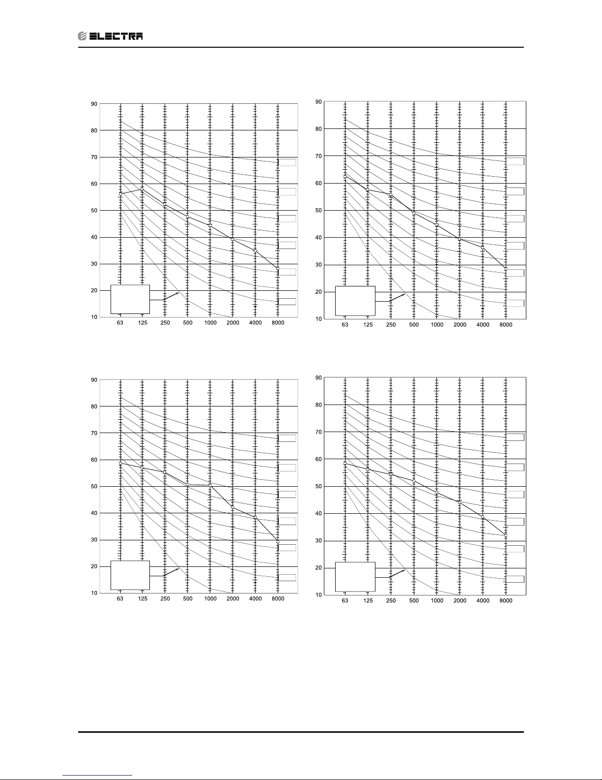
Alpha 9 Cooling Alpha 9 Heating
Alpha 12 Cooling Alpha 12 Heating
BAND CENTER FREQUENCIES, Hz
APPROXIMATE
THRESHOLD OF
HEARING FOR
CONTINUOUS
NOISE
NC-70
NC-60
NC-50
NC-40
NC-30
NC-20
OCTAVE BAND SOUND PRESSURE LEVEL, dB re 0.002 MICRO BAR
BAND CENTER FREQUENCIES, Hz
APPROXIMATE
THRESHOLD OF
HEARING FOR
CONTINUOUS
NOISE
NC-70
NC-60
NC-50
NC-40
NC-30
NC-20
OCTAVE BAND SOUND PRESSURE LEVEL, dB re 0.002 MICRO BAR
BAND CENTER FREQUENCIES, Hz
APPROXIMATE
THRESHOLD OF
HEARING FOR
CONTINUOUS
NOISE
NC-70
NC-60
NC-50
NC-40
NC-30
NC-20
OCTAVE BAND SOUND PRESSURE LEVEL, dB re 0.002 MICRO BAR
BAND CENTER FREQUENCIES, Hz
APPROXIMATE
THRESHOLD OF
HEARING FOR
CONTINUOUS
NOISE
NC-70
NC-60
NC-50
NC-40
NC-30
NC-20
OCTAVE BAND SOUND PRESSURE LEVEL, dB re 0.002 MICRO BAR
Page 29
7-1
ELECTRICAL DATA
Revision Y05-01Service Manual - ALPHA
7. ELECTRICAL DATA
7.1 Single Phase Units
MODEL Alpha 7 Alpha 9 Alpha 12
Power Supply
To indoor To indoor To indoor
1PH-230V-50Hz 1PH-230V-50Hz 1PH-230V-50Hz
Max Current, A 4.1 6.5 7.7
Circuit Breaker,A 10 10 10
Power Supply Wiring No. X
Cross Section mm
2
3x1.0 mm
2
3x1.0 mm
2
3x1.0 mm
2
Interconnecting Cable RC
Model No. X Cross Section mm
2
5x1.0 mm2 +2x0.5 mm
2
(OCT senser)
5x1.0 mm2 +2x0.5 mm
2
(OCT senser)
5x1.0 mm2 +2x0.5 mm
2
(OCT senser)
Interconnecting Cable ST
Model No. X Cross Section mm
2
4x1.0 mm
2
4x1.0 mm
2
4x1.0 mm
2
NOTE
Power wiring cord should comply with local lows and electrical
regulations requirements.
Page 30
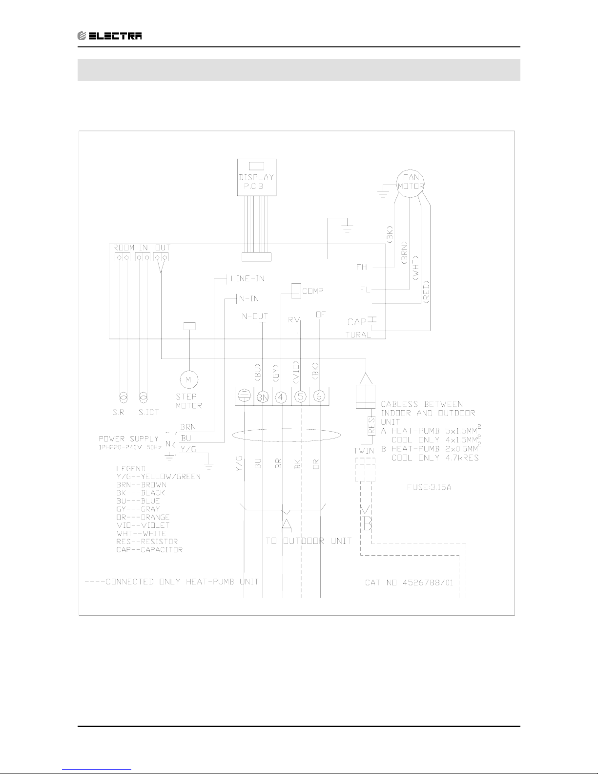
8-1
WIRING DIAGRAMS
Revision Y05-01Service Manual - ALPHA
8. WIRING DIAGRAMS
8.1 Indoor Unit Alpha 7,9,12
Page 31

8-2
WIRING DIAGRAMS
Revision Y05-01 Service Manual - ALPHA
8.2 Outdoor Unit CON 7
8.3 Outdoor Unit CON 7 with easy connection kit
Page 32

8-3
WIRING DIAGRAMS
Revision Y05-01Service Manual - ALPHA
8.4 Outdoor Unit GCN 9, 12
8.5 Outdoor Unit GCN 9,12 with easy connection kit
REV:03
Page 33

9-1
ELECTRICAL CONNECTIONS
Revision Y05-01Service Manual - ALPHA
9. ELECTRICAL CONNECTIONS
9.1 Alpha 7,9,12,
Page 34

10-1
REFRIGERATION DIAGRAMS
Revision Y05-01Service Manual - COMPACT
10. REFRIGERATION DIAGRAMS
10.1 Heat Pump Models
10.1.1 Alpha 7, 9, 12 RC
HEATING MODE
Service
COOLING MODE
Service
Outdoor coil
Sensor
Capillary
tube
Strainer
Check
valve
OUTDOOR UNIT
valve
Reverse
tube
Capillary
Compressor
Outdoor coil
Sensor
tube
Capillary
Reverse
Strainer
valve
Compressor
tube
Capillary
Check
valve
OUTDOOR UNIT
INDOOR UNIT
Flared
connection
Valves
port
Indoor coil
Sensor
INDOOR UNIT
connection
Flared
Valves
port
Indoor coil
Sensor
Page 35

10-2
REFRIGERATION DIAGRAMS
Revision Y05-01 Service Manual - COMPACT
10.2 Cooling Only Models
10.2.1 Alpha 7, 9, 12
Outdoor coil
Strainer
Capillary
tube
Compressor
Service
port
OUTDOOR UNIT
connection
Valves
Flared
Indoor coil
Sensor
INDOOR UNIT
Page 36

11-1
TUBING CONNECTIONS
Revision Y05-01Service Manual - ALPHA
11. TUBING CONNECTIONS
TUBE (Inch)
TORQUE (Nm)
¼” ⅜” ½” ⅝” ¾”
Flare Nuts 11-13 40-45 60-65 70-75 80-85
Valve Cap 13-20 13-20 18-25 18-25 40-50
Service Port Cap 11-13 11-13 11-13 11-13 11-13
1. Valve Protection Cap-end
2. Refrigerant Valve Port (use Allen wrench to open/close)
3. Valve Protection Cap
4. Refrigerant Valve
5. Service Port Cap
6. Flare Nut
7. Unit Back Side
8. Copper Tube
When the outdoor unit is installed above the indoor unit an oil trap is required every 5m along
the suction line at the lowest point of the riser. Incase the indoor unit is installed above the
outdoor, no trap is required.
Page 37

12-1
CONTROL SYSTEM
Revision Y05-01Service Manual - ALPHA
12. CONTROL SYSTEM ALPHA 7-12
12.1 Electronic Control
12.1.1 Introduction
The electronic control information is designed for service applications, and is common
to the following groups of air-conditioners:
• ST/ RC group -Cooling only / cooling and heating by heat pump.
• SH group -Cooling and heating by heat pump and supplementary
heater.
• RH group -Cooling, heating by heaters only.
12.1.2 Jumpers Settings
GROUP J6 Setting J2 Setting
ST / RC Open Open
SH Closed Open
RH Closed Closed
Page 38

12-2
CONTROL SYSTEM
Revision Y05-01 Service Manual - ALPHA
12.2 Legend
AC - Alternate Current
A/C - Air-Conditioner
ANY - ON or OFF status
CLOCK - ON/OFF Operation Input, (dry contact)
COMP - Compressor
CPU - Central Processing Unit
ELUM - Extended Louver Upward Movement (Software Jumper)
E²PROM, EEP - Erase Enable Programmable Read Only Memory
HE - Heating Element
HPC - High Pressure Control
H/W - Hardware
ICP - Indoor Condensation Pump
ICT - Indoor Coil Temperature (RT2) sensor
IF, IFAN - Indoor Fan
IR - Infra Red
LEVEL1 - Normal Water Level
LEVEL2/3 - Medium/High Water Level
LEVEL4 - Overflow Level
Max - Maximum
Min - Minimum
min - Minute (time)
NA - Not Applicable
OCP - Outdoor Condensation Pump
OCT - Outdoor Coil Temperature (RT3) sensor
OF, OFAN - Outdoor Fan
OPER - Operate
Para. - Paragraph
RAT - Return Air Temperature (RT1) sensor
RC - Reverse Cycle (Heat Pump)
R/C - Remote Control
RCT - Remote Control Temperature
RH - Resistance Heater
RT - Room Temperature (i.e. RCT in IFEEL mode, RAT otherwise)
RV - Reversing Valve
SB, STBY - Stand-By
sec - Second (time)
Sect - Section
SH - Supplementary Heater
SPT - Set Point Temperature
ST - Standard (a Model with Cooling Only)
S/W - Software
TEMP - Temperature
W/O - Without
WVL - Water Valve
∆T - The difference between SPT and RT.
in Heat Mode: ∆T = SPT-RT
in Cool/Dry/Fan Mode: ∆T = RT-SPT
Page 39

12-3
CONTROL SYSTEM
Revision Y05-01Service Manual - ALPHA
12.3 Main PCB Controller
12.3.1 COMPACT 7-12 (LEXAN) COMPACT 7-22 Display PCB
STBY LED IR RECIVER
MODE BUTTONOPR’ LED
STBY LED
OPR’ LED
IR RECIVER
MODE BUTTON
Page 40

12-4
CONTROL SYSTEM
Revision Y05-01 Service Manual - ALPHA
12.4 General functions
12.4.1 COMP operation
For each Mode including POWER OFF & SB, a Min time delay of 3 min
before COMP restarting, excluding DEICING Mode
The Min operation time of COMP under different operating conditions is
Operation Mode
Min operation time of
COMP
Heat, Cool or Auto Modes 3 min.
Fan, Dry, Overflow, Protection modes, or mode change ignored
12.4.2 IFAN operation
• Min time interval between IFAN speed change in AUTOFAN Mode, is 30 sec.
• Min time interval between IFAN speed change in H/M/L Mode is 1 sec.
• IFAN speed in Heat/Cool Autofan Mode is determined according to the following table:
∆T IFAN Speed
∆T ≥ 2 HIGH
2 ≥ ∆T ≥ 1 MED
1 ≥ ∆T LOW
where in Heat Mode: ∆T = SPT-RT
in Cool Mode: ∆T = RT-SPT
Note:
• In Heat Mode, the rules in section 4.0.3 have the higher priority.
• The table above can be represent by a hysteresis curve which
will minimize the switching of the IFAN relay and will minimize the
change in IFAN speed:
T [oc]
L
M
H
IFAN speed
321
12.4.3 OFAN operation
• Min time interval between OFAN ON/OFF state change is 30 sec.
• In general, OFAN starts together with COMP.
12.4.4 HE operation
• Minimum Heaters ON or OFF time is 30 sec.
• Heaters can be activated only if IFAN is on.
Page 41

12-5
CONTROL SYSTEM
Revision Y05-01Service Manual - ALPHA
12.4.5 Protections
• High pressure protection is applicable to all operating modes.
• Deicing control is valid in Heat and Auto Heat Mode only.
• Defrosting control is valid in Dry, Cool, Heat and Auto Modes.
• No reset after protection modes.
12.4.6 Thermistors operation
• Return air Temp. is detected by RAT (RT1) in normal Mode, or by RCT (R/C sensor)
in I-FEEL Mode.
• Indoor Coil Temp. is detected by ICT (RT2).
12.4.6.1 Definition of thermistor faults:
a. Thermistor is disconnected -
The thermistor reading is below -30
o
c.
b. Thermistor is shorted -
The thermistor reading is over 75
o
c.
c. Thermistor Temp reading doesn’t change (irrelevant for RT1) -
(i) This test is performed only once after a unit is switched from
OFF/STBY to operation. At the first occurrence of 10 min
continuous COMP operation, the current ICT & OCT are
compared with those when the COMP was switched from OFF
to ON 10 min before. If the ∆T is less than 3
o
c, the thermistor is
regarded as defective.
(ii) The ICT and OCT no-change error can be disabled together by
connecting a4.7 kohm resistor (5%) to the OCT connector. These
resistors are equivalent to a thermistor at 43+/-1
o
c and 48+/-1oc
respectively.
(iii) Connecting a 4.7k resistor to the ICT connector will disable the
ICT no-change error only.
Page 42

12-6
CONTROL SYSTEM
Revision Y05-01 Service Manual - ALPHA
12.4.6.2 Handling the thermistor faults in a COMP unit
i. ICT/OCT thermistor is disconnected or shorted -
The invalid thermistor temperature is replaced by 43oc, so that the unit
can continue the normal operation. All protections related to that faulty
thermistor will be disabled. For example, in case of any ICT fault, the ICT
high pressure protection in Heat Mode and ICT defrost protection in Cool
Mode will not operate anymore. The same is also applied to the OCT fault.
ii. RAT thermistor is disconnected or shorted –
The RAT will be derived from the ICT by using the equations :
Heat Mode: RAT=ICT/2.3
Cool Mode RAT=ICT*4
Notes:
• In case of any thermistor failure, the STBY LED will be blinking until the
fault condition is corrected.
• User can use the system diagnostics function to find out the nature of
the thermistor faults.
i. RAT thermistor is disconnected or shorted –
System will operate continuously in the last IFAN & WVL status when
turned ON.
Notes:
• As in the COMP unit, the STBY LED will be blinking to indicate a
thermistor fault. And, the user can use the system diagnostics function
to find out the nature of the fault.
Page 43

12-7
CONTROL SYSTEM
Revision Y05-01Service Manual - ALPHA
12.5 Cooling Mode - General
1) Room Temperature, RT, is detected by
• RAT in normal operation, or
• RCT (R/C sensor) in I-FEEL mode.
2) The resolution of RT is 1oc.
• RT is activating COMP/WVL if (RT > SPT), and
• RT is stopping COMP/WVL if (RT =< SPT).
3) Indoor Coil Temp is detected by ICT (RT2).
4) Outdoor Coil Temp is detected by OCT (RT3).
5) OFAN OPERATIONS
• OFAN starts together with COMP in general.
Page 44

12-8
CONTROL SYSTEM
Revision Y05-01 Service Manual - ALPHA
2.5.1 Cooling
Mode: Cool, Auto (at Cooling)
Temp: Selected desired temperature.
Fan: HIGH, MED, LOW
Timer: Any
I Feel: On or Off
Control function
Maintains room temp at desired level by comparing RT and SPT.
(RT - SPT) [oc]
+3
+2
+1
0
-1
-2
ON
OFF
ON
OFF
USER FAN SPEED
ON
OFF
COMP
(WVL)
OFAN
IFAN
RV
Note:
1) IFAN is always running at High, Medium or Low speed selected by user.
2) In IFEEL mode, the Room Temperature (RT) is the RCT from a R/C. Otherwise, the
RT is the RAT from the Room Thermistor.
Page 45

12-9
CONTROL SYSTEM
Revision Y05-01Service Manual - ALPHA
12.5.2 Cooling with Autofan
Mode: Cool, Auto (at cooling)
Temp: Selected desired temperature
Fan: Auto
Timer: Any
I Feel: On or Off
Control function
Maintains room temp at desired level and controls the IFAN speed for optimal comfort.
(RT - SPT) [oc]
+3
+2
+1
0
-1
-2
ON
OFF
ON
OFF
H
L
M
ON
OFF
COMP
(WVL)
OFAN
IFAN
RV
Page 46

12-10
CONTROL SYSTEM
Revision Y05-01 Service Manual - ALPHA
12.6 Heating Mode
12.6.1 Heating Mode - General
• In heating Mode, temp. compensation schedule will be activated for wall mounted
units.
SPT [oc]
Add to SPT
I-FEEL ON I-FEEL OFF
18 ≤ SPT ≤ 27 0
o
c +2 oc
27 < SPT ≤ 30 0
o
c+3
o
c
Notes :
• No compensation will be activated in Forced operation modes
12.6.2 IF operating rules
• As a general rule for RC and SH groups, when COMP is ON, excluding
protection modes, IFAN will be switched ON if
• ICT > 35oc or
at the IFTC 30 sec after the COMP is switched ON. In
this case, the IFAN will be started at low speed.
Notes :
1) In SH or RC group, if HE is set to OFF due to low ICT, IFAN will be
switched to LOW and will be turned OFF after 30 sec.
2) An exception to this rule (4.0.3.a) is the Back-up mode for SH.
• In RC and SH groups, whenever COMP & HE are both
OFF, excluding protection modes, IFAN operation will be according
to the following:
In other models IFAN will operate in low speed for 30 sec and then stop. If
COMP is OFF for more than 3 minutes and IFEEL Mode is inactive, IFAN will
operate in low speed according to the following graph:
IFAN Speed
Any
Low
Stop
30 35 40
EMD/ELD
EMD/ELD
ICT [oc]
15 20 25
General :
For WAX :
SPT+4 SPT+6 ICT
[
o
c
]
ON
OFF
IFAN (Low Speed)
Page 47

12-11
CONTROL SYSTEM
Revision Y05-01Service Manual - ALPHA
12.6.3 HE operation
• For all Groups, HE can be ON only when IFAN is ON.
• For all Groups, HE switches to OFF when ICT > 50
o
c, and is activated
again when ICT ≤ 45oc.
• In SH or RC group, HE operation is limited by the following graph:
• Back-up mode for SH group
After COMP has been working for 5 minutes, HE & IFAN are activated even
if the ICT is still below 35
o
c. This situation is called Back-up Mode. Both
HE & IFAN will work in Back-up Mode until the ICT reaches 35oc. Then, the
operation goes on in the usual mode .
HE
ON
OFF
30
45 50
ICT [oc]
15
General :
For WAX :
35
20
40
Page 48

12-12
CONTROL SYSTEM
Revision Y05-01 Service Manual - ALPHA
12.6.4 Heating, RC or SH Group
Mode: Heat, Auto (at heating)
Temp: Selected desired temperature
Fan: HIGH, MED, LOW
Timer: Any
I Feel: On or Off
Control function
Maintains room temp. at desired level by comparing RAT or RCT to SPT.
(RT - SPT) [oc]
+2
+1
0
-1
-2
-3
ON
OFF
ON
OFF
H/M/L
OFF
L
ON
OFF
Note 1 Note 2
COMP
(WVL)
HE1
HE2
IFAN
ON
OFF
RV
Page 49

12-13
CONTROL SYSTEM
Revision Y05-01Service Manual - ALPHA
12.6.5 Heating, RC or SH Group with Autofan
Mode: Heat, Auto (at heating)
Temp: Selected desired temperature
Fan: Auto
Timer: Any
I Feel: On or Off
Control function
Maintains room temp at desired level by controlling COMP, IFAN and OFAN.
(RT - SPT) [oc]
+2
+1
0
-1
-2
-3
ON
OFF
ON
OFF
H
OFF
L
M
ON
OFF
Note 1 Note 2
COMP
(WVL)
HE1
HE2
IFAN
RV
ON
OFF
Page 50

12-14
CONTROL SYSTEM
Revision Y05-01 Service Manual - ALPHA
12.6.6 OFAN operation is controlled by the graph below when
1. (RAT ≥ SPT – 2oc), AND
2. (ICT ≥ 45
o
c), AND
3. (COMP is ON)
Otherwise, OFAN runs together with COMP.
OCT [oc]
+3
+2
+1
0
-1
OFAN
ON
OFF
Page 51

12-15
CONTROL SYSTEM
Revision Y05-01Service Manual - ALPHA
12.7 Automatic Cooling or Heating
12.7.1 Automatic Cooling or Heating - General
• Switching-temperature between Cooling and Heating is SPT ± 3oc.
• Autofan in Automatic Cooling and Heating Mode will activate “Cooling
with Autofan Mode” and “Heating with Autofan Mode” respectively.
• When the Auto Mode is started with SPT +/-0
o
c, the unit will not select
Auto Heat or Auto Cool mode immediately. Instead, the unit will be in
a temporary Fan Mode with IFAN operating at low speed.
The proper Auto Heat mode or Auto Cool will be started whenever the RT
reaches SPT-1oc or SPT+1oc respectively.
• For RC & SH units, Mode change between Auto Heat & Auto Cool
Modes is possible only after the COMP has been OFF during the
last T minutes.
Mode Change time, T
Auto Cool to Auto Heat 3 min
Auto Heat to Auto Cool 4 min
• When unit is changed form Cool/Dry mode to Auto Mode, the unit
will continue to operate at (Auto) Cool Mode until the conditions for
switching from Auto Cool to Auto Heat are satisfied.
Similarly, when unit is changed from Heat Mode to Auto Mode, the
unit will continue to operate at (Auto) Heat Mode until the conditions
for switching from Auto Heat to Auto Cool are satisfied.
Page 52

12-16
CONTROL SYSTEM
Revision Y05-01 Service Manual - ALPHA
12.7.2 Auto Cooling or Heating, RC or SH Groups
Mode: Auto
Temp: Selected desired temperature
Fan: Any
Timer: Any
I Feel: On or Off
Control function
Maintains room temp at desired level by selecting between cooling and heating modes.
(RT - SPT) [oc]
+3
+2
+1
0
-1
-2
-3
ON
OFF
ON
OFF
H/M/L/OFF
L/OFF
ON
OFF
ON
OFF
COMP
& OFAN
HE1
HE2
IFAN
RV
H/M/L/OFF
L/OFF
USER FAN SPEED H/M/L/OFF
L/OFF
Auto Cool Mode Auto Heat Mode
> 4 min > 3 min
> 3 min > 2 min
(3) (3)
(4)
(4)
(5)
Auto Heat Mode
Page 53

12-17
CONTROL SYSTEM
Revision Y05-01Service Manual - ALPHA
12.8 Dry Mode
12.8.1 Dry, ST or RC group
Mode: Dry
Temp: Selected desired temp
Fan: Low (automatically selected by software)
Timer: Any
I FEEL: Any
Control function
Reduce room humidity with minimum temp. fluctuations by operating in Cool Mode with
low speed IFAN.
Notes :
• When Dry is ON, the COMP is forced OFF for 3.5 min (longer than the
3 min Min COMP-Off time) after every 15 min of continuous COMP
operation.
• When Dry is OFF, the COMP is forced ON for 6 min (longer than the 3
min Min COMP-On time) after every 15 min of continuous COMP OFF
time.
• When Dry is changed from ON to OFF or vice versa, the limits
mentioned in (1) & (2) are ignored. The COMP operation is only
controlled by the 3 min Min OFF time and 1 min Min ON time.
• In Dry Mode, IFAN is LOW when COMP is ON, and is OFF when
COMP is OFF.
DRY
(RT - SPT) [oc]
+2
+1
0
-1
-2
ON
OFF
ON
OFF
LOW
OFF
DRY-ON
DRY-OFF
ON
OFF
Time [min]
10
20
30
40 50
Max 15 minutes
3.5
min
Note1
6 min
Note 2
COMP
& OFAN
HE1
& HE2
IFAN
RV
Max 15 minutes
5 minutes COMP
ON time
Page 54

12-18
CONTROL SYSTEM
Revision Y05-01 Service Manual - ALPHA
12.9 Protection
12.9.1 Cooling Mode Protections
Indoor Coil Defrost
Mode: Cooling, Dry, Auto
Temp: Selected desired temp.
Fan: Any
Timer: Any
I Feel: On or Off
Control Function
Protect the indoor coil from ice formation at low ambient temperature.
t1 = 5 min minimum for each COMP starting
t2 = OFAN cycling (alternate between ON and OFF every 30 sec) for 20 min
maximum
t3 = COMP and OFAN stop for 10 min minimum
Notes:
• When J7 is closed (connected), OFAN cycling is cancelled and the
set temperature for COMP & OFAN cut-out and cut-in are changed.
COMP & OFAN are forced OFF when ICT =< -6oc, and are kept OFF
until ICT > 14oc.
• For WAX model, the defrost processes is simpler. When J7 is open,
COMP & OFAN are forced OFF when ICT =< -1oc, and are kept OFF
until ICT > 5oc. When J7 is closed, the WAX defrosting process is the
same as that of the other models (R.H.S. of the graph above). In both
cases, the ICT checking in t2 and t3 are not applied.
ICT [oc]
+2
ON
OFF
ON
OFF
t1 t2 t3
COMP
OFAN
+1
+5
+14
0
-1
-6
ON
OFF
IFAN
J7 OPEN J7 CLOSED
t1 t1
Page 55

12-19
CONTROL SYSTEM
Revision Y05-01Service Manual - ALPHA
12.9.2 High Pressure Protection
Mode: (Auto) Cooling or Dry
Temp: Selected desired temp.
Fan: Any
Timer: Any
I Feel: On or Off
Control Function
To protect the COMP from the high pressure built-up in the outdoor coil during normal
cooling operation, by switching OFF the IFAN and COMP.
OCT [oc]
Any
OFF
Any
ON
Any
Blink
ON
COMP
OFAN
IFAN
OPER
LED
52
55
61
66
L
COMP is forced OFF
OFAN is forced ON
IFAN forced
to LOW
68
OFAN follow operation of
COMP
COMP is forced OFF
OFAN is forced ON
For all models except WAX & P2000 For WAX & P2000 models
Note:
• The ICT is also monitored during Cool and Dry mode, in case the RV control circuit
is faulty. Whenever ICT reaches 70oc, which indicates a high pressure in the indoor
coil, the COMP will be forced off automatically. The COMP can be turned on again only
after the ICT is under 70oc again and after the 3 min COMP ON delay time. The OPER
LED will not blink in this case.
Page 56

12-20
CONTROL SYSTEM
Revision Y05-01 Service Manual - ALPHA
12.9.3 Heating Mode Protections
Outdoor coil Deicing (excluding RH Group)
Mode: Heating, Auto (at heating)
Temp: Selected desired Temp
Fan: Any
Timer: Any
I FEEL: Any
Control function
Protects the Outdoor coil from ice formation by controlling COMP & RV operation.
Scope
This new deicer is designed to operate at extreme temp conditions. The deicing cycle
could be triggered from:
1. OCT temp and time between two consecutive deicing cycles.
2. Detection of ice forming by change of the OCT temp.
Both algorithms adjust the time between deicing cycles to optimize the A/C
performance. The algorithm will automatically increase the time between deicing cycles
and reduce the deicing cycle as needed.
The algorithm uses EEPROM data to operate.
Page 57

12-21
CONTROL SYSTEM
Revision Y05-01Service Manual - ALPHA
Deicing procedure
OCT [oc]
ON
OFF
ON
OFF
ON
L
ANY
COMP
OFAN
RV
IFAN
DST
(DDT)
0
12
OFF
HEs are forced ON
DOC
ANY
ON
HE
36s 36s
DT
30s
max 12 min.
Note 3
DI (note 1)
DI (note 2)
30s
3 min 3 min
IFAN
OFF
ANY
HE
OFF
ANY
all SH units
except WAX
RC or WAX units
HEs are forced OFF
IFAN is forced to Low Speed
BLINK
ON
OPER
LED
Notes :
• At the first COMP activation after SB or OFF, if (OCT < 0oc), then DI = 10
min, else DI = 40 min.
• In the following Deicing cycles, the time interval between two Deicing
cycles activation is between 30 to 80 min (refer to the flow chart).
• For RC group, HEs are forced OFF. IFAN operation is as in Heat
Mode, Sect 4.0.3.a, i.e. IFAN will be set to OFF when ICT<30
o
c.
For WAX, the IFAN is simply forced OFF.
• For SH group, HEs are forced ON and IFAN is forced to operate in Low
speed, regardless of the ICT and difference between RAT & SPT.
Page 58

12-22
CONTROL SYSTEM
Revision Y05-01 Service Manual - ALPHA
12.9.4 High pressure protection (excluding RH Group)
Mode: (Auto) Heating
Fan: Any
Timer: Any
I Feel: On or Off
Control Function
Protect the Compressor from high pressure by switching OFF the OFAN and COMP.
ICT [oc]
Any
Off
Any
Off
COMP
OFAN
52
55
61
66
COMP is forced OFF
67
OFAN is force
Off
COMP is forced OFF
For all models except WAX For WAX model
ON
BLINK
OPER
LED
Notes:
• IFAN, HE1 and HE2 will be activated according to the relevant
Heating Mode Sect.
• In case of any malfunction in the relay control circuit, the OCT is also
monitored during heating mode. Whenever OCT reaches 70
o
c, which indicates
a high pressure in the outdoor coil, the COMP will be forced off automatically.
The COMP can be turned on again only after the 3 min COMP ON delay and the
OCT is under 70oc. The OPER LED will not blink in this case.
Page 59

12-23
CONTROL SYSTEM
Revision Y05-01Service Manual - ALPHA
12.10 Timer
Mode: Any
Temp. Selected desired temp
Fan: Any
Timer: Timer On, Timer Off
I Feel: On or Off
Control function
• Starts or stops the unit operation after pre-set time. If RC-1 is used,
the timer setting will be (0.5 - 24 Hr) from the moment the timer is set.
The minimum resolution is 30 minutes.
If RC-2 or later version of remote controls is used, the timer
setting will be (0:00 - 23:50) real time with 10 minutes resolution.
• After power failure, all pre-set timers are cleared. The system is
forced to STBY mode and the Timer LED indicator is blinked to
indicate the situation. The LED keeps blinking until the timer settings
can be reloaded from a R/C message.
Note: If all timers are inactive, the system will not be forced
OFF after the power failure. The last OPER/STBY status will
be loaded from the EEP instead.
• When the A/C receives any valid message from a R/C, the current
ON/OFF timer settings will be replaced by the new timer settings in
the R/C message.
Note: The following timer related operations will not affect the
A/C operating mode (Heat/Cool/Auto/Dry/Fan) setting.
• Set ON/OFF timer
• Clear ON/OFF timer
• R/C ON Timer is time-up
• R/C OFF Timer is time-up
E.g. When a STBY A/C unit (with Cool Mode setting in its EEP) is
turned on by the ON-TIMER of a R/C with heat mode setting,
the A/C will start in Cool Mode.
Page 60

12-24
CONTROL SYSTEM
Revision Y05-01 Service Manual - ALPHA
12.11 Forced Operation
Forced operation allows units to start, stop and operate in Cooling or Heating in pre-set
temperature according to the following table:
Forced operation
mode
Pre-set Temp for :
WMZ, WMF,WNG models
Cooling 22°C
Heating 28°C
Note:
• While under the forced operation, the temperature compensation
schedule.
• The forced operation is activated when the mode button on the
Display Board is used to switch the unit to Cool or Heat mode.
• The IFAN is always set to Autofan Speed in forced operation.
Page 61

12-25
CONTROL SYSTEM
Revision Y05-01Service Manual - ALPHA
12.12 Sleep Mode
Mode: Any
Temp: Set – desired temperature selected
Fan: Any
Timer: Interact with Sleep Timer as described in sect 12.2
I Feel: On or Off
The Sleep mode is activated by using the sleep button on the R/C. In Sleep Mode,
the unit will automatically adjust the SPT to turn up/down the room temperature (RT)
gradually to provide maximum comfort to the user in sleep.
Sleep is treated as TIMER function. Therefore, the TIMER LED is activated similar to
TIMER function.
12.12.1 Adjustment in Sleep Mode
1. in cool, auto cool or dry modes, the SPT adjustment is positive (from 0 to +3oc).
2. In heat or auto heat modes, the SPT adjustment is negative (from 0 to -3
o
c).
3. In other modes, there is no SPT adjustment.
4. The SPT adjustment is cancelled when the Sleep mode is cancelled.
Note: If Off-timer is active, the unit may go to SB before or after 7 hours of
sleep operation.
SPT
Time [Hr]
485326
Start
Sleep
7
RT
SPT-1
SPT-2
SPT-3
SPT+2
SPT+1
SPT+3
1
7 Hours Sleep operation
for Normal Sleep Mode
Unit is turned to SB
after Sleep
Cool, Dry modes
Heat mode
Page 62

12-26
CONTROL SYSTEM
Revision Y05-01 Service Manual - ALPHA
12.12.2 Time adjustment in Sleep Mode
The user can make use of the Off-Timer to extend the Sleep Time from 7 hours to 12
hour (max). The operation of the new “Extended Sleep Mode” is illustrated by the
graphs below.
Case 1 is the Standard Sleep Mode, which is the only sleep mode in previous version
of MCU. The A/C unit simply works for 7 hours, then goes to SB.
Case 2 is the new Extended Sleep Mode. If an active Off-Timer is set to turn off the
A/C between 7-12 hour, relative to the starting of Sleep, the Sleep time is extended.
And, instead of going to SB at the 7th hour, the A/C will work until reaching the Off-time.
Case 3 is an exception to case 2. The Sleep Mode will not be extended to the Off-Time
when the Off-Timer is preceded by an On-Timer, which is also between 7-12 hour.
Oper
Time [Hr]
48101226
Start
Sleep
7
Case 1 : Standard Sleep Mode
Condition : Off-timer is not set or is beyond 12 hour.
SB
Oper
Time [Hr]
48101226
Start
Sleep
7
Case 2 : Extended Sleep Mode
Condition : Off-timer is set at 7-12 hour.
SB
Off-timer
Oper
Time [Hr]
48101226
Start
Sleep
7
Case 3 : Exception to Case 2
Condition : Off-timer is set at 7-12 hour
On-timer is set at 7-12 hour and before Off-timer
SB
Off-timerOn-timer
Page 63

12-27
CONTROL SYSTEM
Revision Y05-01Service Manual - ALPHA
12.13 Controller Self-Test Procedure
12.13.1 By Shorting Test Jumper J1
RC/ST TEST
MODEL
CONFIGURATION
TEST
STEP MOTOR TEST
FREQUENCY
TEST
LEDS OFF
LEDS ON TEST
AUTO RELAY
TEST
SHORT JUMPER
J1
(CONTROL PCB)
PRESS ON
POWER
BUTTON
PRESS ON
MODE BUTTON
INDOOR FAN
SPEED TEST
SELF-TEST FLOW CHART
Step 1
Step 2
Step 3
FOR CONTROLLER (VERSION 4V5 OR HIGHER)
COOL
HEAT
COMPRESSOR
OUTDOOR FAN
R.V.
LOW
MEDIUM
HIGH
TIMER
OPERATE
STANDBY
BUZZER TEST
(ONE BEEP SOUND)
REMOTE CONTROL
TO CPU COMUNICATION
(TWO BEEPS SOUNDS)
THERMISTOR ANALOG
VOLTAGE CHECKING
EEPROM MEMORY
TEST
END OF SELF
TEST
PRESS ON RESET
BUTTON
PRESS ON FAN
BUTTON ON THE
REMOTE CONTROL
PRESS ON MODE
BUTTON
PRESS ON MODE
BUTTON
Step 4
Step 5
Step 6
Step 7
Step 8
DISCONNECT
JUMPER
J1
Page 64

12-28
CONTROL SYSTEM
Revision Y05-01 Service Manual - ALPHA
12.13.2 By Remote Control Settings:
a. 1: TURNING ON THE POWER.
Turn ON the power, make sure that the unit is in operation.
b. STEP 2 : ENABLE SELF-TEST MODE
• Use the remote control to send the first settings to display / indoor unit
HEAT mode, HIGH IFAN, set temperature to 16 ºC, no I-FEEL Sleep or
any other timer settings are needed.
• Cover the IR transmitter components in the remote control so that it will
not transmit the signals to the indoor unit display.
• Use the remote control to send the second settings to display / indoor unit
COOL mode, LOW IFAN, no I-FEEL Sleep or any other timer settings.
• Uncover the remote control IR transmitter and change the temperature
settings. If the display/indoor unit receive the settings properly the
following steps will start:
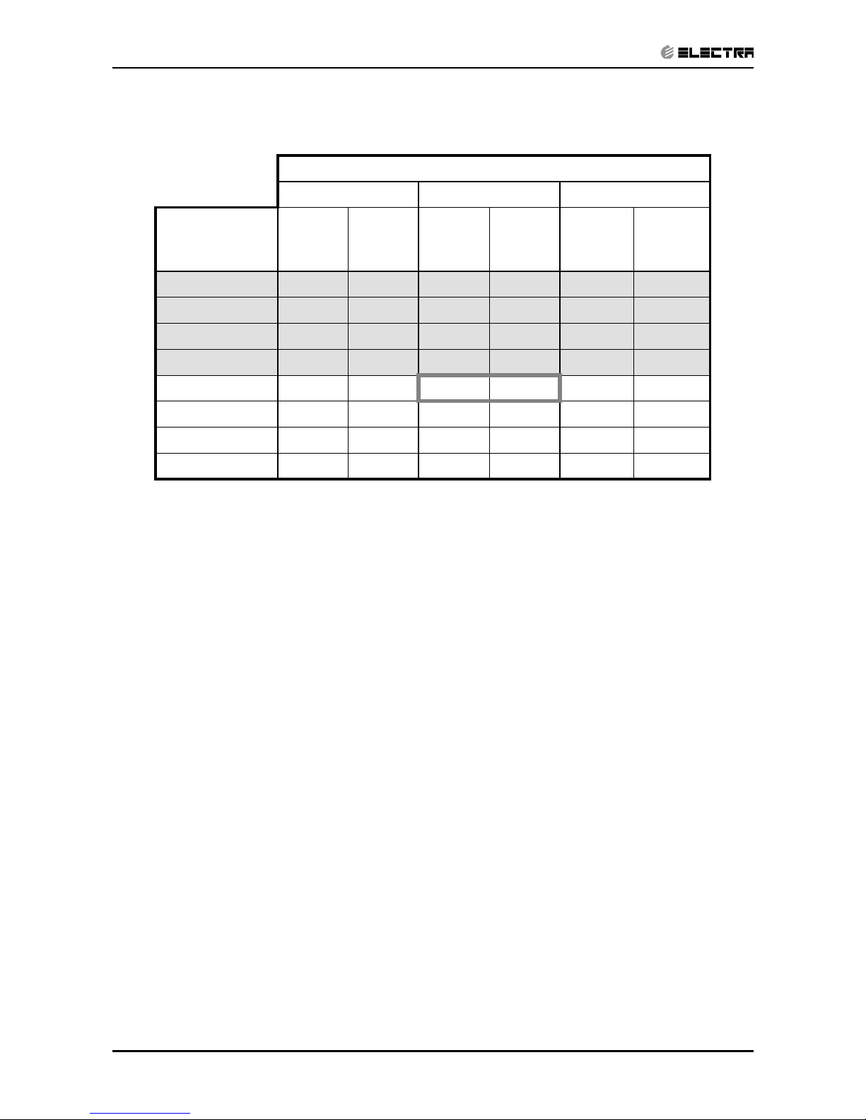
c. STEP 3: MODEL SETTING CONFIRMATION
• The STAND-BY and COOL LEDS will indicate the operation mode as
follows:
OPERATION MODE STAND-BY LED COOL LED
ST ON OFF
RC OFF OFF
SH OFF ON
RH ON ON
• Testing the Model configuration. Selected by the COMP, STAND-BY,
TIMER LEDS and FILTER will indicate the model configuration as follows
(the relevant line for this manual is highlighted):
MODEL COMP OPERATE LED TIMER LED FILTER LED
WNG ON OFF OFF OFF
WMZ ON ON OFF ON
WMN4 OFF OFF ON OFF
WMN2/WHX OFF ON OFF ON
WMN3 OFF ON ON ON
In this term the step motor will turn to HOME POSITION.
Page 65

12-29
CONTROL SYSTEM
Revision Y05-01Service Manual - ALPHA
d. STEP 4 : AUTO LED WALK TEST.
• All the LEDS will turn OFF.
• All the LEDS will turn ON for 1 second one by one in the following
sequence:
STAND-BY OPERATE TIMER FILTER COOL HEAT.
• In PRX all the LEDS will turn ON for 1 second one by one in the following
sequence : 18 °c 20 °c 22 °c 24 °c 26 °c 28 °c 30 °c
High IFAN Auto IFAN Med IFAN Low IFAN STAND-BY
TIMER FILTER COOL HEAT.
e. STEP 5: AUTO REALY WALK TEST:
• All relays will energize one by one in the following sequence:
COMPRESSOR OUTDOOR FANR. V. HEATER 1 HEATER 2
INDOOR WATER PUMP SWING or OUTDOOR WATER PUMP
INDOOR FAN: LOW MID HIGH.
• When the relay walk test is completed, the next test will start
automatically.
f. STEP 6: FREQUENCY TESTING:
• If the frequency measuring process fails the COOL LED will turn ON.
In order to move to the next step, press ON/OFF button on the remote
control.
g. STEP 7: INPUT TEST.
• The test purpose is to check the analog real time indicators (thermistors,
LEVEL and clock) according to the table below.
LED Indicator Condition for LED to be ON
STBY LED Room thermistor ≠ 25°c
OPER LED Indoor coil thermistor ≠ 25°c
TIMER LED Outdoor coil thermistor ≠ 25°c
FILTER LED Clock
COOL LED LEVEL 2&3
HEAT LED LEVEL 4
h. STEP 8: TIMING RESET TEST (WATCH DOG).
• The test purpose is to verify that the CPU rise time after power failure
is between 1 to 3 sec, test results are indicated on the LEDS : STANDBY,OPER, TIMER and FILTER turning ON one by one.
• The results of the test are coded as follows:
Pass condition:
1 sec - STAND-BY and OPER are turned ON
2 sec - STAND-BY, OPER and TIMER are turned ON
Page 66

12-30
CONTROL SYSTEM
Revision Y05-01 Service Manual - ALPHA
Fail condition:
0 sec - STAND-BY is turned ON
3 sec - STAND-BY, OPER, TIMER and FILTER are turned ON
• When the timing reset test is completed, the next test will start
automatically.
i. STEP 9: MEMORY TEST (EEPROM)
• The test purpose is to check if the memory is functioning correctly. The test
result is reported by using the STAND-BY and FILTER LEDS:
LED Indicator Condition for LED to be ON
STAND-BY LED Test passed
FILTER LED Test failed
AT THIS POINT THE SELF-TEST IS COMPLETED.
In order to terminate Self-Test mode the User can change the unit setting from COOL
Mode, LOW FAN to COOL Mode, MED FAN or to wait without using the remote control
for 60 sec.
Values of Sensors Temperature VS. Voltage (DC)
Temp. (*C) Voltage (V) Temp. (*C) Voltage (V) Temp. (*C) Voltage (V) Temp. (*C) Voltage (V)
-20 4.554 2 3.744 24 2.555 46 1.487
-19 4.529 3 3.695 25 2.5 47 1.447
-18 4.502 4 3.646 26 2.445 48 1.409
-17 4.475 5 3.595 27 2.391 49 1.371
-16 4.446 6 3.544 28 2.338 50 1.334
-15 4.417 7 3.492 29 2.284 51 1.298
-14 4.386 8 3.439 30 2.232 52 1.263
-13 4.354 9 3.386 31 2.18 53 1.228
-12 4.322 10 3.332 32 2.128 54 1.195
-11 4.287 11 3.278 33 2.077 55 1.162
-10 4.252 12 3.223 34 2.027 56 1.13
9 4.216 13 3.168 35 1.978 57 1.099
-8 4.178 14 3.113 36 1.929 58 1.069
-7 4.14 15 3.058 37 1.881 59 1.04
-6 4.1 16 3.002 38 1.834 60 1.011
-5 4.059 17 2.946 39 1.798 61 0.983
-4 4.017 18 2.89 40 1.742 62 0.956
-3 3.974 19 2.833 41 1.698 63 0.929
-2 3.93 20 2.777 42 1.654 64 0.904
-1 3.885 21 2.722 43 1.611 65 0.879
0 3.839 22 2.666 44 1.569 66 0.854
1 3.792 23 2.61 45 1.527 67 0.831
Page 67

12-31
CONTROL SYSTEM
Revision Y05-01Service Manual - ALPHA
12.14 On Unit Indicators and Controls
STAND BY
INDICATOR
Lights up when the Air Conditioner is connected to power and
ready to receive the R/C commands
Blinks continuously in case of any thermistor failure.
OPERATION
INDICATOR
Lights up during operation.
Blinks for 300 ms, to announce that a R/C infrared signal has
been received and stored.
Blinks continuously during
• OCT High Pressure Protection Mode
• ICT High Pressure Protection Mode
• Deicing in Heating Mode
• Water Over Flow in ECC Model
MODE BUTTON
(Cool, Heat, SB)
Use to cycle the operation mode of the A/C unit among COOL,
HEAT and SB modes, without using the R/C.
Every time this switch is pressed, the next operation mode is
selected, in this order :
SB Cool Mode Heat Mode SB ...
Press this button continuously for 5 sec or more to start the
Diagnostic Mode.
Page 68

12-32
CONTROL SYSTEM
Revision Y05-01 Service Manual - ALPHA
12.15 Clock Random Delay From 0 to 2.5 seconds
0 = Clock Switch Open
1 = Clock Switch close
The Clock is activate according to the following table:
A/C STATE
(before clock is changed)
CLOCK STATE
(before clock is changed)
CLOCK ACTION
(clock is changed)
A/C NEW STATE
(after clock is changed)
ON 1 0 OFF
OFF 0 1 ON
OFF by
interrupt
(1)
10OFF
ON by
interrupt
(1)
01ON
Notes :
1. Clock can be interrupted by :
• R/C - POWER ON/OFF Push-button.
• R/C - TIMER.
• R/C - SLEEP.
• A/C - MODE SWITCH.
2. Any change in the CLOCK level during the first 6 sec after the system
Reset is ignored.
Page 69

13-1
TROUBLESHOOTING
Revision Y05-01Service Manual - ALPHA
13. TROUBLESHOOTING
NO SYMPTON PROBABLE CAUSE CORRECTIVE ACTION
1. The stand-by
indicator (red led)
on the central
control display
panel doesn’t light
up.
There is no correct voltage
between the line and neutral
terminals on main P.C.B
-If the voltage is low repair power
supply.
-If there is no voltage repair
general wiring.
-If there is correct voltage replace
main or display P.C.B’S
2. The operation
indicator (green
led) on the central
control display
panel does not
light up.
The remote control batteries
are discharged
-Replace batteries of the remote
control.
3. The operation
indicator (green
led) does not light
up when starting
from unit.
Check main P.C.B and display
P.C.B
-Replace P.C.B if necessary.
4. The indoor fan
does not function
correctly.
Check the voltage between
indoor fan terminals on the
main P.C.B
-If there is voltage replace
capacitor or motor.
5. The outdoor fan
does not function
correctly.
Check the voltage between out
door fan terminals on the main
P.C.B
There is voltage between
outdoor fan terminals on the
outdoor unit.
There is no voltage between
outdoor fan terminals on the
outdoor unit.
-If there is no voltage replace main
P.C.B
-Replace capacitor or motor.
-Check and repair electrical wiring
between indoor and outdoor units.
6. The compressor
does not start up.
Check voltage on compressor
terminals on the outdoor unit.
(with ammeter)
Check if there is correct voltage
between compressor terminals
on the outdoor unit.
-If no voltage replace main P.C.B
-If low voltage repair power supply.
-If the voltage correct replace
capacitor or compressor.
-If there is no voltage repair
electrical wiring between indoor
and outdoor units.
7. The refrigeration
system does not
function correctly.
Check for leaks or restrictions.
With ammeter. Pressure gauge
or surface thermometer.
-Repair refrigeration system and
charge refrigerant if necessary.
Page 70

13-2
TROUBLESHOOTING
Revision Y05-01 Service Manual - ALPHA
NO SYMPTON PROBABLE CAUSE CORRECTIVE ACTION
8 No cooling or
heating only
indoor fan works.
Outdoor fan motor faulty or
other fault caused, compressor
overload protection cut out.
-Replace P.C.B.
-Outdoor fan blocked remove
obstructions.
9. Only indoor fan
and compressor
working.
Outdoor fan blocked. -Remove obstructions.
10. Only indoor fan
working.
-Run capacitor of outdoor fan
motor faulty.
-Windings of outdoor fan are
shorted.
-Replace capacitor.
-Replace motor.
11. No cooling or
heating takes
place, indoor fans
working.
-Overload safety device on
compressor is cut out (low
voltage or high temperature).
-Compressor runs capacitor
faulty.
-Compressor windings are
shorted.
-Check for proper voltage, switch
off power and try again after one
hour.
-Replace compressor capacitor.
-Replace compressor.
12. No air supply
at indoor unit,
compressor
operates.
-Indoor fan motor is blocked or
turns slowly.
-Indoor fan run capacitor faulty.
-Motor windings are shorted.
-Check voltage, repair wiring if
necessary.
-Check fan wheel if it is tight
enough on motor shaft, tighten if
necessary.
13. Partial, limited air
supply at indoor
unit.
Lack of refrigerant (will
accompanied by whistling
noise) cause ice formation on
indoor unit coil in cooling mode.
-charge the unit after localizing
leak.
14. Water
accumulates
and over flow
from indoor unit
section.
Drain tube or spout of drain pan
clogged.
-Disassemble plastic drain tube
from spout of indoor unit drain pan.
15. Water dripping
from outdoor unit
base, (in heating
mode).
Water drain outlet is clogged. -Open outdoor unit cover clean out
water outlet clean the base inside
thoroughly.
16. Freeze-up of
outdoor coil in
heating mode,
poor heating effect
in room, indoor fan
operates.
-Faulty outdoor thermistor.
-Faulty control cable.
-Outdoor temperature is below
design conditions.
-Outdoor unit air outlet is
blocked.
-Replace thermistor.
-Repair control cable.
-Shut unit off, it cannot work
properly.
-Remove obstructions.
17. Unit is in heat
mode but
operating in
cooling.
-Faulty RV coil.
-RV coil is ok valve is stuck
position.
-Replace RV coil.
-Replace the reversing valve.
Page 71

14-1
EXPLODED VIEWS AND SPARE PARTS LISTS
Revision Y05-01Service Manual - ALPHA
14. EXPLODED VIEWS AND SPARE PARTS LISTS
14.1 Indoor Unit Alpha 7, 9, 12
5
6
7
Page 72

14-2
EXPLODED VIEWS AND SPARE PARTS LISTS
Revision Y05-01 Service Manual - ALPHA
14.2 Indoor Unit Alpha 7, 9
No. Part No. Description Qty
4525979 Grille A
1
4527484 Grille B
1
4527485 Grille C
1
2
4525989
A
ir Filter
2
3
4523901
A
ctive Carbon Filter (Optional)
2
4
4525990 Filter Support (Optional)
2
4527003 Printing Frame “Electra”for Isreal
1
4527004 Printing Frame “Fagor”
1
452700501
Printing Frame “AIWELL”
1
452700502 Printing Frame “GORNEJE”
1
452700503 Printing Frame “Belair”
1
452700504 Printing Frame “Relax”
1
452700505 Printing Frame “No brand”
1
452700506 Printing Frame “OCEAN”
1
452700507 Printing Frame “BOSCH”
1
452700508 Printing Frame “SIEMENS”
1
452700509 Printing Frame “Electra”for European
1
452700510 Printing Frame “Climair”
1
452700511 Printing Frame “Johnson”
1
6
4525987 Screw Cover
3
7
453070700 Coil Assy.
1
8
126233 Nut brass 1/4’
1
9
434530 Nut brass 3/8’
1
10
4523526 Beraing Assy.
1
11
4523523 Fan Assy. Plastic
1
12
4523505 Motor IOD-7
1
4527112 Motor IOD-9
1
4526649
A
ir Outlet Assy. (Israel market)
1
452784400
A
ir Outlet Assy.(except Israel market) 1
14
4525991 Louver
1
15
4523693 Drain Hose
1
16
4526659 Rear Panel Assy.
1
17
453027400 Mount Bracket
1
18
4526000 Tube Clip
1
19
4523507 Step Motor
1
20
438600 Remote Controller RC3
1
412040 Remote Controller RC5-RC 1
4526132 Power Cord Cable(Iseral)
1
4526133 Power Cord Cable(Europe 2m)
1
4524040 Power Cord Cable(Austrilia)
1
4526134 Power Cord Cable(no plug)
1
4526136 Power Cord Cable(Europe 3m)
1
22 4525998 Motor Cover 1
23
4516263 Sensor Base 1
24
452778400 Display Assy
1
25
452778300 Control Box Assy.
1
453124100 Control Box Assy. (easy connecter)
1
4525988 Cable Locker
1
27
436525 Cable Locker
1
28
438082 Thermistor Indoor Coilblack
1
29
4519813 Thermistor Roomred
1
30
453027000 Terminal Cover
1
21
26
1
5
13
Page 73

14-3
EXPLODED VIEWS AND SPARE PARTS LISTS
Revision Y05-01Service Manual - ALPHA
14.3 Indoor Unit Alpha 12
No. Part No. Description Qty
4527501 Grille A
1
4527502 Grille B
1
4527503 Grille C
1
2
4527507
A
ir Filter
2
3
4527359
A
ctive Carbon Filter (Optional)
2
4
4527508 Filter Support (Optional)
2
452766800 Printing Frame “Electra”for Isreal
1
452766801 Printing Frame “AIRWELL”
1
452766802 Printing Frame “GORNEJE”
1
452766803 Printing Frame “Belair”
1
452766804 Printing Frame “Relax”
1
452766805 Printing Frame “Electra”for Europent
1
452766806 Printing Frame “Fagor”
1
452766807 Printing Frame “No brand”
1
452766808 Printing Frame “OCEAN”
1
452766809 Printing Frame “BOSCH”
1
452766810 Printing Frame “SIEMENS”
1
452766811 Printing Frame “Johnson”
1
6
4525987 Screw Cover
3
7
453058200 Coil Assy.
1
8
126233 Nut brass 1/4’
1
9
434530 Nut brass 3/8’
1
10
4523526 Beraing Assy.
1
11
4527111 Fan Assy. Plastic
1
12
4527112 Motor IOD-12
1
4527187
A
ir Outlet Assy. (Israel market)
1
452784401
A
ir Outlet Assy.(except Israel market)
1
14
4527509 Louver
1
15
4523693 Drain Hose
1
16
4527186 Rear Panel Assy.
1
17
453027500 Mount Bracket
1
18
4527512 Tube Clip
2
19
4523507 Step Motor
1
20
438600 Remote Controller RC3
1
412040 Remote Controller RC5-RC
1
4526132 Power Cord Cable(Iseral)
1
4526133 Power Cord Cable(Europe 2m)
1
4524040 Power Cord Cable(Austrilia)
1
4526134 Power Cord Cable(no plug)
1
4526136 Power Cord Cable(Europe 3m) 1
22 4525998 Motor Cover 1
23
4516263 Sensor Base 1
24
452778400 Display Assy.
1
452778300 Control Box Assy.
1
453124100 Control Box Assy. (easy connecter)
1
26
4525988 Cable Locker
1
27
436525 Cable Locker
1
28
438082 Thermistor Indoor Coilblack
1
29
4519813 Thermistor Roomred
1
30
453027000 Terminal Cover
1
1
5
13
21
25
Page 74

14-4
EXPLODED VIEWS AND SPARE PARTS LISTS
Revision Y05-01 Service Manual - ALPHA
14.4 Outdoor Unit CON 7 RC
3
4
5
6
7
891011
12
13
14
15
16
17
18
19
2
33
32 31
29
30
28
20
21
22
23
24
27
25
26
Page 75

14-5
EXPLODED VIEWS AND SPARE PARTS LISTS
Revision Y05-01Service Manual - ALPHA
14.5 Outdoor Unit CON 7 RC
No. Part No. Description Qty
1 436358 L.lifter 1
2 4526671 Front Panel 1
3 4526481 CON Outdoor Grille 1
4 4527483 Screw ST4X10-C-H DK>9 1
5 453044400 Partition plate 1
6 4525427 Clip for capacitance 1
7 455000108 Double patch Capacitor for fan motor 2uF 1
8 236179 2 Poles Terminal Block 1
9 453057000 Pedestal/Control 1
10 4514588 5 Poles Terminal Block 1
11 453054500 Clip/cables 1
12 455000502 Compressor Capacitor With Screw 25uF (CBB65) 1
13 453056700 Rubber grommet/base plate 4
14 452964500 Compressor Assy. PA82X1C-4DZDE(R410A GMCC) 1
15 4510677 Nut With Flange M8 -D=24 GB6187-86 3
16 4524278 Wire assy 1
17 4516637 Out sensor Black 1
18 453045400 Base Plate 1
19 453046100 Low Pressure Stop Valve OD9.53 R410A 1
20 453046200 High Pressure Stop Valve OD6.35 R411A 1
21 4520071 4-W Valve coil for R410A 1
22 453044200 4-W Valve Welding assy 1
23 4518951 4-W valve SHF-4H for R410A 1
24 453045600 Capillary assy 1
25 4526669 Side Panel Painting 1
26 4526668 R lifter 1
27 453057500 Condenser Assy 1
28 4526143 Linker of motor support assy 1
29 453045000 Motor Support 1
30 4523609 Motor YDK20-6L 1
31 4523707 AXIAL FAN 1
32 4526675 Top Cover Painting 1
33 453121500 Install Accessory 1
Page 76

14-6
EXPLODED VIEWS AND SPARE PARTS LISTS
Revision Y05-01 Service Manual - ALPHA
14.6 Outdoor Unit CON 7 ST
3
5
4
6
7
8
9
10
11
12
13
14
15
16
17
18
2
32
31 30
28
29
27
19
20
21
22
23
26
24
25
Page 77

14-7
EXPLODED VIEWS AND SPARE PARTS LISTS
Revision Y05-01Service Manual - ALPHA
14.7 Outdoor Unit CON 7 ST
No. Part No. Description Qty
1 436358 L.lifter 1
2 4526671 Front Panel 1
3 4526481 CON Outdoor Grille 1
4 4527483 Screw ST4X10-C-H DK>9 1
5 453044400 Partition plate 1
6 4525427 Clip for capacitance 1
7 455000108 Double patch Capacitor for fan motor 2uF 1
8 453057000 Pedestal/Control 1
9 4514588 5 Poles Terminal Block 1
10 453054500 Clip/cables 1
11 455000502 Compressor Capacitor With Screw 25uF (CBB65) 1
12 453056700 Rubber grommet/base plate 4
13 452964500 Compressor Assy. P
A
82X1C-4DZDE(R410A GMCC) 1
14 4510677 Nut With Flange M8 -D=24 GB6187-86 3
15 4524278 Wire assy 1
16 453183600 Discharge Pipe Assy 1
17 453045400 Base Plate 1
18 453046100 Low Pressure Stop Valve OD9.53 R410
A
1
19 453046200 High Pressure Stop Valve OD6.35 R411
A
1
20 453112700 Connect Pipe 6.35X0.8 1
21 453126300 Capillary 2.6X1.4X1400 1
22 453112600 Suction Pipe 2 1
23 453112400 Suction Pipe 1 1
24 4526669 Side Panel Painting 1
25 4526668 R lifter 1
26 453057500 Condenser Assy 1
27 4526143 Linker of motor support assy 1
28 453045000 Motor Support 1
29 4523609 Motor YD
K
20-6L 1
30 4523707
A
XIAL FAN 1
31 4526675 Top Cover Painting 1
32 453166600 Install Accessory 1
Page 78

14-8
EXPLODED VIEWS AND SPARE PARTS LISTS
Revision Y05-01 Service Manual - ALPHA
14.8 Outdoor Unit CON 7 RC with easy connection kit
3
5
4
6
7
891011
12
13
14
15
16
17
18
19
29
2
33
32
31 30
20
21
22
23
24
28
27
25
26
Page 79

14-9
EXPLODED VIEWS AND SPARE PARTS LISTS
Revision Y05-01Service Manual - ALPHA
14.9 Outdoor Unit CON 7 RC with easy connection kit
No. Part No. Description Qty
1 436358 L.lifter 1
2 4526671 Front Panel 1
3 4526481 CON Outdoor Grille 1
4 4527483 Screw ST4X10-C-H DK>9 1
5 453044400 Partition plate 1
6 4525427 Clip for capacitance 1
7 453054400 Fixing plate/Terminal Plate 1
8 453057000 Pedestal/Control 1
9 453080600 Terminal Socket/ALPHA Controller 1
10 453054500 Clip/cables 1
11 455000502 Compressor Capacitor With Screw 25uF (CBB65) 1
12 453056700 Rubber grommet/base plate 4
13 452964500 Compressor Assy. P
A
82X1C-4DZDE(R410A GMCC) 1
14 4510677 Nut With Flange M8 -D=24 GB6187-86 3
15 453112800 Power Cord/Compressor 1
16 453122600 Discharge Pipe Assy 1
17 453045400 Base Plate 1
18 453046100 Low Pressure Stop Valve OD9.53 R410
A
1
19 453046200 High Pressure Stop Valve OD6.35 R411
A
1
20 453112700 Connect Pipe 6.35X0.8 1
21 453126300 Capillary 2.6X1.4X1400 1
22 453112600 Suction Pipe 2 1
23 453112400 Suction Pipe 1 1
24 4526669 Side Panel Painting 1
25 4526668 R lifter 1
26 453057500 Condenser Assy 1
27 4526143 Linker of motor support assy 1
28 453045000 Motor Support 1
29 453057200 Motor 1
30 4523707
A
XIAL FAN 1
31 4526675 Top Cover Painting 1
32 453084800 Connect Pipe Ass
y
./1/4'+3/8'
/
A
lpha7,9,12ST 1
Page 80

14-10
EXPLODED VIEWS AND SPARE PARTS LISTS
Revision Y05-01 Service Manual - ALPHA
14.10 Outdoor Unit CON 7 ST with easy connection kit
3
5
4
6
7
8
9
10
11
12
13
14
15
16
17
18
19
2
32
31
21
20
22
23
24
25
Page 81

14-11
EXPLODED VIEWS AND SPARE PARTS LISTS
Revision Y05-01Service Manual - ALPHA
14.11 Outdoor Unit CON 7 ST with easy connection kit
No. Part No. Description Qty
1 436358 L.lifter 1
2 4526671 Front Panel 1
3 4526481 CON Outdoor Grille 1
4 4527483 Screw ST4X10-C-H DK>9 1
5 453044400 Partition plate 1
6 4525427 Clip for capacitance 1
7 453054400 Fixing plate/Terminal Plate 1
8 236179 2 Poles Terminal Block 1
9 453057000 Pedestal/Control 1
10 453080600 Terminal Socket/ALPHA Controller 1
11 453054500 Clip/cables 1
12 455000502 Compressor Capacitor With Screw 25uF (CBB65) 1
13 453056700 Rubber grommet/base plate 4
14 452964500 Compressor Assy. P
A
82X1C-4DZDE(R410A GMCC) 1
15 4510677 Nut With Flange M8 -D=24 GB6187-86 3
16 453112800 Power Cord/Compressor 1
17 4516637 Out sensor Black 1
18 453045400 Base Plate 1
19 453046100 Low Pressure Stop Valve OD9.53 R410
A
1
20 453046200 High Pressure Stop Valve OD6.35 R411
A
1
21 453118500 4-W Valve coil/ R410
A
1
22 453183700 4-W Valve Welding assy 1
23 4518951 4-W valve SHF-4H for R410
A
1
24 453045600 Capillary assy 1
25 4526669 Side Panel Painting 1
26 4526668 R lifter 1
27 453057500 Condenser Assy 1
28 4526143 Linker of motor support assy 1
29 453045000 Motor Support 1
30 453057200 Motor 1
31 4523707
A
XIAL FAN 1
32 4526675 Top Cover Painting 1
33 453085100 Connect Pipe Ass
y
./1/4'+3/8'
/
A
lpha7,9,12RC 1
Page 82

14-12
EXPLODED VIEWS AND SPARE PARTS LISTS
Revision Y05-01 Service Manual - ALPHA
14.12 Outdoor Unit GCN 9, 12 RC
Page 83

14-13
EXPLODED VIEWS AND SPARE PARTS LISTS
Revision Y05-01Service Manual - ALPHA
14.13 Outdoor Unit GCN 9 RC R22
No. Part No. Description Qty
1 4516158 PAINTED COVER PANEL ASSY. 1
2 4522551 Grill A of GCN 1
3 436358 Left Handle 1
4 4523441 Front Panel A Painting Assy. 1
5 4516907 Base Painting Assy. 1
6 453086200 Side Plate Painting Assy. 1
7 4516857 Big Side Cover 1
8 204107 Cable Clip Nylon 1
9 253046 Clip set PVC 1
10 236332 6 Poles Terminal Block 1
11 236179 2 Poles Terminal Block 1
12 4511168 Wire Clip 1
13 4518022 Cap. Clip 1
14 201130 Nut (For Capacitor) 1
15 203008 Washer (For Capacitor) 1
16 455000108 Double patch Capacitor for fan motor 2uF 1
17 455000502 Compressor Capacitor With Screw 25uF (CBB65) 1
18 453090300 Compressor Assy. P
A
-108X1C-4FZDE 1
19 452795300 Nut With Flange M6 3
20 391498
W
ire assy
1
21 453047000 Gas Valve 1
22 453046900 Liquid Valve 1
23 453091500 4-Way Valve System Ass
y
.1
24 4520071 4-Way Valve coil 1
25 4518951 4-Way Valve 1
26 453091600 Capillary assy 1
27 4516156 Back Panel 1
28 4516637 Outdoor Unit Sensor 1
29 453090700 Condensor Assy. 1
30 453086000 Patition Plate 1
31 323156 Motor Support 1
32 4522765 Fan Motor 1
33 4519251 Fan 1
34 4519300 Nut M8 (For Fan) 1
35 453166600 Install Accessory 1
Page 84

14-14
EXPLODED VIEWS AND SPARE PARTS LISTS
Revision Y05-01 Service Manual - ALPHA
14.14 Outdoor Unit GCN 12 RC
No. Part No. Description Qty
1 4516158 PAINTED COVER PANEL ASSY. 1
2 4522551 Grill A of GCN 1
3 436358 Left Handle 1
4 4523441 Front Panel A Painting Assy. 1
5 4523862 Base Painting Assy. 1
6 453086200 Side Plate Painting Assy. 1
7 4516857 Big Side Cover 1
8 204107 Cable Clip Nylon 1
9 253046 Clip set PVC 1
10 236332 6 Poles Terminal Block 1
11 236179 2 Poles Terminal Block 1
12 4511168 Wire Clip 1
13 4518022 Cap. Clip 1
14 201130 Nut (For Capacitor) 1
15 203008 Washer (For Capacitor) 1
16 455000108 Double patch Capacitor for fan motor 2uF 1
17 455000504 Compressor Capacitor With Screw 35uF (CBB65) 1
18 4526452 Comp.
A
ssy PA145X2C-4FT 1
19 4510677 Nut With Flange M8 -D=24 GB6187-86 3
20 391498
W
ire assy
1
21 453047000 Gas Valve 1
22 453046900 Liquid Valve 1
23 453092700 4-Way Valve System Ass
y
.1
24 4520071 4-Way Valve coil 1
25 4518952 4-Way Valve 1
26 453092800 Capillary assy 1
27 4516156 Back Panel 1
28 4516637 Outdoor Unit Sensor 1
29 453092100 Condensor Assy. 1
30 453086000 Patition Plate 1
31 323156 Motor Support 1
32 4522766 Fan Motor 1
33 4519251 Fan 1
34 4519300 Nut M8 (For Fan) 1
35 453166600 Install Accessory 1
Page 85

14-15
EXPLODED VIEWS AND SPARE PARTS LISTS
Revision Y05-01Service Manual - ALPHA
14.15 Outdoor Unit GCN 9,12 ST
Page 86

14-16
EXPLODED VIEWS AND SPARE PARTS LISTS
Revision Y05-01 Service Manual - ALPHA
14.16 Outdoor Unit GCN 9 ST
No. Part No. Description Qty
1 4516158 PAINTED COVER PANEL ASSY. 1
2 4522551 Grill A of GCN 1
3 436358 Left Handle 1
4 4523441 Front Panel A Painting Assy. 1
5 4516907 Base Painting Assy. 1
6 453086200 Side Plate Painting Assy. 1
7 4516857 Big Side Cover 1
8 204107 Cable Clip Nylon 1
9 253046 Clip set PVC 1
10 236332 6 Poles Terminal Block 1
11 236179 2 Poles Terminal Block 1
12 4511168 Wire Clip 1
13 4518022 Cap. Clip 1
14 201130 Nut (For Capacitor) 1
15 203008 Washer (For Capacitor) 1
16 455000108 Double patch Capacitor for fan motor 2uF 1
17 455000502 Compressor Capacitor With Screw 25uF (CBB65) 1
18 453090300 Compressor Assy. P
A
-108X1C-4FZDE 1
19 452795300 Nut With Flange M6 3
20 391498
W
ire assy
1
21 453047000 Gas Valve 1
22 453046900 Liquid Valve 1
23 453086900 Suction tube 1
24 453087000 Discharge 1 1
25 4526865 Muffle 1
26 453091300 Discharge 2 1
27 453121700 Capillary 1
28 4516156 Back Panel 1
29 453090700 Condensor Assy. 1
30 453086000 Patition Plate 1
31 323156 Motor Support 1
32 4522765 Fan Motor 1
33 4519251 Fan 1
34 4519300 Nut M8 (For Fan) 1
35 453166600 Install Accessory 1
Page 87

14-17
EXPLODED VIEWS AND SPARE PARTS LISTS
Revision Y05-01Service Manual - ALPHA
14.17 Outdoor Unit GCN 12 ST
No. Part No. Description Qty
1 4516158 PAINTED COVER PANEL ASSY. 1
2 4522551 Grill A of GCN 1
3 436358 Left Handle 1
4 4523441 Front Panel A Painting Assy. 1
5 4523862 Base Painting Assy. 1
6 453086200 Side Plate Painting Assy. 1
7 4516857 Big Side Cover 1
8 204107 Cable Clip Nylon 1
9 253046 Clip set PVC 1
10 236332 6 Poles Terminal Block 1
11 236179 2 Poles Terminal Block 1
12 4511168 Wire Clip 1
13 4518022 Cap. Clip 1
14 201130 Nut (For Capacitor) 1
15 203008 Washer (For Capacitor) 1
16 455000108 Double patch Capacitor for fan motor 2uF 1
17 455000504 Compressor Capacitor With Screw 35uF (CBB65) 1
18 4526452 Comp.
A
ssy PA145X2C-4FT 1
19 4510677 Nut With Flange M8 -D=24 GB6187-86 3
20 391498
W
ire ass
y
1
21 453047000 Gas Valve 1
22 453046900 Liquid Valve 1
23 453087500 Suction tube 1
24 453087600 Discharge 1 1
25 453091000 Muffle 1
26 453092500 Discharge 2 1
27 4516156 Capillary 1
28 4516156 Back Panel 1
29 453092100 Condensor Assy. 1
30 453086000 Patition Plate 1
31 323156 Motor Support 1
32 4522766 Fan Motor 1
33 4519251 Fan 1
34 4519300 Nut M8 (For Fan) 1
35 453166600 Install Accessory 1
Page 88

14-18
EXPLODED VIEWS AND SPARE PARTS LISTS
Revision Y05-01 Service Manual - ALPHA
14.18 Outdoor Unit GCN 9, 12 RC with easy connection kit
Page 89

14-19
EXPLODED VIEWS AND SPARE PARTS LISTS
Revision Y05-01Service Manual - ALPHA
14.19 Outdoor Unit GCN 9 RC with easy connection kit
No. Part No. Description Qty
1 4516158 PAINTED COVER PANEL ASSY. 1
2 4522551 Grill A of GCN 1
3 436358 Left Handle 1
4 4523441 Front Panel A Painting Assy. 1
5 4516907 Base Painting Assy. 1
6 453086200 Side Plate Painting Assy. 1
7 4516857 Big Side Cover 1
8 204107 Cable Clip Nylon 1
9 253046 Clip set PVC 1
10 170906 Brass Hex Nut GB6170 2
11 170466 Washer star GB862.2 4 2
12 170716 Screw M4x12 GB818-76 2
13 236179 2 Poles Terminal Block 1
14 4511168 Wire Clip 1
15 453080600 Terminal Socket/ Alpha Controller 1
16 201130 Nut (For Capacitor) 1
17 203008 Washer (For Capacitor) 1
18 453054400 Fixing plate/Terminal plate 1
19 455001002 Combinated Capacitor With Screw (25+2)uF (CBB65) 1
20 453090300 Compressor Assy. P
A
-108X1C-4FZDE 1
21 452795300 Nut With Flange M6 3
22 453112800
W
ire assy
1
23 453047000 Gas Valve 1
24 453046900 Liquid Valve 1
25 453182300 4-Way Valve System Ass
y
.1
26 4520071 4-Way Valve coil 1
27 4518951 4-Way Valve 1
28 453091600 Capillary assy 1
29 4516156 Back Panel 1
30 4516637 Outdoor Unit Sensor 1
31 453090700 Condensor Assy. 1
32 453086000 Patition Plate 1
33 323156 Motor Support 1
34 453114100 Fan Motor 1
35 4519251 Fan 1
36 4519300 Nut M8 (For Fan) 1
37 453085100 Connect Pipe Ass
y
./1/4'+3/8'
/
A
lpha7,9,12RC 1
Page 90

14-20
EXPLODED VIEWS AND SPARE PARTS LISTS
Revision Y05-01 Service Manual - ALPHA
14.20 Outdoor Unit GCN 12 RC with easy connection kit
No. Part No. Description Qty
1 4516158 PAINTED COVER PANEL ASSY. 1
2 4522551 Grill A of GCN 1
3 436358 Left Handle 1
4 4523441 Front Panel A Painting Assy. 1
5 4523862 Base Painting Assy. 1
6 453086200 Side Plate Painting Assy. 1
7 4516857 Big Side Cover 1
8 204107 Cable Clip Nylon 1
9 253046 Clip set PVC 1
10 170906 Brass Hex Nut GB6170 2
11 170466 Washer star GB862.2 4 2
12 170716 Screw M4x12 GB818-76 2
13 236179 2 Poles Terminal Block 1
14 4511168 Wire Clip 1
15 453080600 Terminal Socket/ Alpha Controller 1
16 201130 Nut (For Capacitor) 1
17 203008 Washer (For Capacitor) 1
18 453054400 Fixing plate/Terminal plate 1
19 455001001 Combinated Compressor Capacitor With Screw (35+2)
u
1
20 4526452 Comp.
A
ssy PA145X2C-4FT 1
21 4510677 Nut With Flange M8 -D=24 GB6187-86 3
22 391498
W
ire ass
y
1
23 453047000 Gas Valve 1
24 453046900 Liquid Valve 1
25 453182400 4-Way Valve System Ass
y
.1
26 453121400 4-Way Valve coil 1
27 4518952 4-Way Valve 1
28 453092800 Capillary assy 1
29 4516156 Back Panel 1
30 4516637 Outdoor Unit Sensor 1
31 453092100 Condensor Assy. 1
32 453086000 Patition Plate 1
33 323156 Motor Support 1
34 453114200 Fan Motor 1
35 4519251 Fan 1
36 4519300 Nut M8 (For Fan) 1
Page 91

14-21
EXPLODED VIEWS AND SPARE PARTS LISTS
Revision Y05-01Service Manual - ALPHA
14.21 Outdoor Unit GCN 9, 12 ST with easy connection kit
Page 92

14-22
EXPLODED VIEWS AND SPARE PARTS LISTS
Revision Y05-01 Service Manual - ALPHA
14.21 Outdoor Unit GCN 9 ST with easy connection kit
No. Part No. Description Qty
1 4516158 PAINTED COVER PANEL ASSY. 1
2 4522551 Grill A of GCN 1
3 436358 Left Handle 1
4 4523441 Front Panel A Painting Assy. 1
5 4516907 Base Painting Assy. 1
6 453086200 Side Plate Painting Assy. 1
7 4516857 Big Side Cover 1
8 204107 Cable Clip Nylon 1
9 253046 Clip set PVC 1
10 170906 Brass Hex Nut GB6170 2
11 170466 Washer star GB862.2 4 2
12 170716 Screw M4x12 GB818-76 2
13 236179 2 Poles Terminal Block 1
14 4511168 Wire Clip 1
15 453080600 Terminal Socket/ Alpha Controller 1
16 201130 Nut (For Capacitor) 1
17 203008 Washer (For Capacitor) 1
18 453054400 Fixing plate/Terminal plate 1
19 455001002 Combinated Capacitor With Screw (25+2)uF (CBB65) 1
20 453090300 Compressor Assy. P
A
-108X1C-4FZDE 1
21 452795300 Nut With Flange M6 3
22 453112800
W
ire assy
1
23 453047000 Gas Valve 1
24 453046900 Liquid Valve 1
25 453086900 Suction tube 1
26 453087000 Discharge 1 1
27 4526865 Muffle 1
28 453091300 Discharge 2 1
29 453121700 Capillary 1
30 4516156 Back Panel 1
31 453090700 Condensor Assy. 1
32 453086000 Patition Plate 1
33 323156 Motor Support 1
34 453114100 Fan Motor 1
35 4519251 Fan 1
36 4519300 Nut M8 (For Fan) 1
37 453085100 Connec 2RC
Page 93

14-23
EXPLODED VIEWS AND SPARE PARTS LISTS
Revision Y05-01Service Manual - ALPHA
14.21 Outdoor Unit GCN 12 ST with easy connection kit
No. Part No. Description Qty
1 4516158 PAINTED COVER PANEL ASSY. 1
2 4522551 Grill A of GCN 1
3 436358 Left Handle 1
4 4523441 Front Panel A Painting Assy. 1
5 4523862 Base Painting Assy. 1
6 453086200 Side Plate Painting Assy. 1
7 4516857 Big Side Cover 1
8 204107 Cable Clip Nylon 1
9 253046 Clip set PVC 1
10 170906 Brass Hex Nut GB6170 2
11 170466 Washer star GB862.2 4 2
12 170716 Screw M4x12 GB818-76 2
13 236179 2 Poles Terminal Block 1
14 4511168 Wire Clip 1
15 453080600 Terminal Socket/ Alpha Controller 1
16 201130 Nut (For Capacitor) 1
17 203008 Washer (For Capacitor) 1
18 453054400 Fixing plate/Terminal plate 1
19 455001001 Combinated Compressor Capacitor With Screw (35+2)uF (CBB65) 1
20 4526452 Comp.
A
ssy PA145X2C-4FT 1
21 4510677 Nut With Flange M8 -D=24 GB6187-86 3
22 391498
W
ire assy
1
23 453047000 Gas Valve 1
24 453046900 Liquid Valve 1
25 453182400 4-Way Valve System Ass
y
. 1
26 453121400 4-Way Valve coil 1
27 4518952 4-Way Valve 1
28 453092800 Capillary assy 1
29 4516156 Back Panel 1
30 4516637 Outdoor Unit Sensor 1
31 453092100 Condensor Assy. 1
32 453086000 Patition Plate 1
33 323156 Motor Support 1
34 453114200 Fan Motor 1
35 4519251 Fan 1
36 4519300 Nut M8 (For Fan) 1
37 453085100 Connect Pipe Ass
y
./1/4'+3/8'
/
A
lpha7,9,12RC 1
Page 94

16-1
APPENDIX A
Revision Y05-01
Service Manual - ALPHA
APPENDIX A
INSTALLATION AND OPERATION MANUAL
► INSTALLATION AND OPERATION MANUAL ALPHA 7, 9, 12
Page 95

PROGRAMMING AND OPERATING MANUAL
MANUAL DE UTILIZACION Y DE PROGRAMMACION
CONDIZIONATORE D'ARIA A PARETE SPLIT
ITALIANO
ENGLISH
AIR CONDITIONER SPLIT WALL MOUNTED
CLIMATIZADOR SPLIT MURAL
ESPANOL
MANUALE DI UTILIZZO E DI PROGRAMMAZIONE
FRANCAIS
5
CLIMATISEUR SPLIT MURAL
MANUEL D'UTILTSATION ET DE PROGRAMMATION
KLIMAGERAET IN SPLIT BAUWEISE
DEUTSCH
BEDIENUNGS UND PROGRAMMIERUNGS HANDBUCH
Page 96

AIR CONDITIONER
SPLIT WALL MOUNTED
PROGRAMMING
AND OPERATING
Page 97

CONTENTS
INTRODUCTION
SYSTEM DESCRIPTION
ON-UNIT INDICATORS AND CONTROLS
REMOTE CONTROL
OPERATION MODES, FUNCTIONS AND FEATURES
USE OF WIRELESS REMOTE CONTROL
OPERATION PROCEDURE
·
Turning on the air conditioner
·
Ventilating operation
·
Cooling operation
·
Cooling operation with auto fan mode
·
Heating operation
·
Heating operation with auto fan mode
·
Auto cooling / heating operation
·
Dry operation
·
Selecting the temperature
·
Sleep function
·
Timer operation
·
Automatic vertical air swing
·
Turning off the air conditioner
·
Current clock time set
PROTECTION MODES
CARE AND MAINTENANCE
OPERATING TIPS
PRECAUTIONS
BEFORE CALLING FOR SERVICE
1
2
3
5
6
7
8
8
8
8
8
8
8
9
9
9
9
10
11
11
11
12
13
14
15
16
IF YOUR AIR
CONDITIONER IS FOR
COOLING ONLY, PLEASE
DISREGARD THE
HEATING INSTRUCTIONS
PLEASE READ THESE
INSTRUCTIONS BEFORE
OPERATING THE AIR
CONDITIONER
Page 98

1
INTRODUCTION
This Split Air Conditioner is desighned for versatile applications:
OPERATING TEMPERATURE
RANGE:
Cooling:
21 43 C
OO
~
Heating:
-7 21 C
OO
~
IMPORTANT NOTICE:
This air conditioner must be
grounded to protect against
electrical shock.
Installation of the air
conditioner must be
performed by an experienced
air conditoning installer,
observing good regrigeration
practice.
Electrical connections and
power cord replacement
should only be made by
authorized electricians and in
accordance with electrical
regulations and local codes.
Failure to comply with the
manufacturer's installation
and operation instructions
could affect the performance
of the air conditioner and the
validity of the warranty.
·
·
·
·
(According to T temperature
condition)
1
·
Cooling air in the summer.
·
Heating.
·
Dehumidifying the air at high humidity conditions.
·
Ventilation.
Page 99

2
SYSTEM DESCRIPTION
Air intake grille
1
Supply air flap
(louver)
2
Air filter
3
Power cord
4
Unit's indicators
and on unit control
5
Horizontal air
flow defecting
louvers
6
Suction line
7
Liquid line
8
Power cable
9
Control wire
10
Condensate tube
11
Outdoor unit air
intake
12
Outdoor unit air
outlet
13
Remote control
14
16
Air purifying filter
(optional)
15
Air outlet
14
4
5
3
2
6
15
16
1
12
9
10
11
7
8
13
Page 100

COOL Cools, dehumidifies and filters the room air. Maintains the desired room
temperature.
SLEEP Designed to create comfortable sleeping conditions. When in COOLING mode,
the temperature rises one degree centigrade every hour, for to three hours, from
the start of the mode. The temperature rise prevents the feeling of over-cooling
while sleeping (when your body is at rest). In HEATING mode the reverse occurs;
the air conditioner lowers its temperature one-degree every hour. When in SLEEP
mode, the air conditioner will be automatically turned off after have operated for
seven hours. The result is a more comfortable and invigorating sleep, which leaves
you feeling fresh and energetic on the next morning.
TIMER Real time control and display, automatically turns the air conditioner ON and
OFF according to the time of day setting, ensuring comfort conditions before
returning home, without wasting electricity. It turns the air conditioner off
automatically when sleeping.
HOT KEEP In HEATING and in AUTO FAN, the fan will be turned off when the compressor
is not in operation and will not be restarted, unless the indoor coil reaches
adequate temperature. This HOT KEEP feature prevents uncomfortable cold air
drafts. Use of AUTO FAN is, therefore, recommended when the air conditioner
is in HEATING mode.
AUTO FAN The air conditioner automatically selects the FAN speed in accordance to with the
room temperature. At the start, the unit operates at high fan speed. As the room
air approaches to the desired temperature, the fan switches to a lower speed for
quieter operation.
FAN Recirculates and filters the room air. Maintains constant air movement in
the room.
DRY Dehumidifies and softly cools the room In DRY Mode, the air conditioner
operates at an inceased dehumidifying power. This function is recommended
to be used when temperature is rather low but the humidity is high.
AUTO Automatically switches from COOLING to HEATING or from HEATING to
COOLING, maintaining the desired temperature according to the room conditions.
HEAT Heats and filters the room air. Maintains the desired room temperature.
OPERATION MODES, FUNCTIONS
AND FEATURES
3
AUTO
 Loading...