

Page 1

Service Manual
WNG LED/LCD Series
REFRIGERANT
R410A
R407C
R22
COOLING ONLY
HEAT PUMP
SEPTEMBER - 2005
Indoor Units Outdoor Units
WNG 7 GCN 7 ONG 7
WNG 9 GCN 9 ONG 9
WNG 12 GCN 12 ONG 12
WNG 14 GC 14 ONG 14
WNG 18 GC 18 —
WNG 21 GC 22 —
WNG 24 OU7-24 —
WNG 25 GC 24 —
WNG 30 GC 30 OU8 30/33
WNG 36 OU10-36 —
Page 2
A
LIST OF EFFECTIVE PAGES
Revision Y05-03
Service Manual - WNG
LIST OF EFFECTIVE PAGES
Note: Changes in the pages are indicated by a “Revision#” in the footer of each effected page
(when none indicates no changes in the relevant page). All pages in the following list represent
effected/ non effected pages divided by chapters.
Dates of issue for original and changed pages are:
Original ....... 0 ........ 15 December 2004
Total number of pages in this publication is 537 consisting of the following:
Page
No.
Revision
No. #
Page
No.
Revision
No. #
Page
No.
Revision
No. #
Title ....................... 3
A ........................... 3
i ............................. 1
1-1 - 1-7 ................ 3
2-1 - 2-30 .............. 3
3-1 ........................ 1
4-1 - 4-5 ................ 2
5-1 - 5-116 ............ 4
6-1 - 6-2 ................ 1
7-1 - 7-2 ................ 2
8-1 - 8-8 ................ 2
9-1 - 9-2 ................ 1
10-1-10-9 .............. 3
11-1 ....................... 1
12-1-12-34 ............ 1
12a-1-12a-40 ........ 2
12b-1-12b-18 ........ 1
13-1-13-2 .............. 0
14-1 – 14-143 ....... 3
15-1 – 15-8 ........... 1
Appendix -A ...........2
• Zero in this column indicates an original page.
*Due to constant improvements please note that the data on this service manual can be modified with out notice.
**Photos are not contractual.
Page 3

i
TABLE OF CONTENTS
Revision Y05-03Service Manual - WNG
Table of Contents
1. INTRODUCTION ...................................................................................................1-1
2. PRODUCT DATA SHEET ......................................................................................2-1
3. RATING CONDITIONS ..........................................................................................3-1
4. OUTLINE DIMENSIONS .......................................................................................4-1
5. PERFORMANCE DATA & PRESSURE CURVES ................................................5-1
6. SOUND LEVEL CHARACTERISTICS ..................................................................6-1
7. ELECTRICAL DATA ..............................................................................................7-1
8. WIRING DIAGRAMS .............................................................................................8-1
9. ELECTRICAL CONNECTIONS .............................................................................9-1
10. REFRIGERATION DIAGRAMS .............................................................................10-1
11. TUBING CONNECTIONS ......................................................................................11-1
12. CONTROL SYSTEM .............................................................................................12-1
13. TROUBLESHOOTING ..........................................................................................13-1
14.
EXPLODED VIEWS AND SPARE PARTS LISTS .................................................14-1
15. OPTIONAL ACCESSORIES .................................................................................15-1
16. APPENDIX A .........................................................................................................16-1
Page 4

1-1
INTRODUCTION
Revision Y05-03
Service Manual - WNG
1. INTRODUCTION
1.1 General
The new WNG split wall mounted range comprise the ST (cooling only) and RC (heat
pump) models, as follows:
• Cooling Only WNG 7ST, WNG 9ST, WNG 12ST, WNG 14ST,
WNG 18ST, WNG 21ST, WNG 24ST, WNG 30ST, WNG 36ST
• Heat Pump WNG 7RC, WNG 9RC, WNG 12RC, WNG 14RC,
WNG 18RC, WNG 21RC, WNG 24RC, WNG 30RC,WNG 36RC
The indoor WNG units are available as LED or LCD display types, featuring esthetic
design, compact dimensions, and low noise operation.
Display type models availability:
• LED / LCD Type WNG7, WNG9, WNG12, WNG14, WNG18, WNG21, WNG24
• LCD Type WNG30, WNG36
1.2 Main Features
The WNG series benefits from the most advanced technological innovations, namely:
• R22, R407C and R410A models
• Microprocessor control.
• Infrared remote control with liquid crystal display.
• Supports Indoor Air Quality features, such as – Ionizer, Active Electro-Static Filter,
and Fresh Air.
• Indoor large diameter cross flow fan, allowing low noise level operation.
• Bended indoor coil with treated aluminum fins and coating for improved efficiency.
• High COP.
• Easy access to the interconnecting tubing and wiring connections, so that
removing the front grill or casing is not necessary.
• Refrigerant pipes can be connected to the indoor unit from 6 different optional
directions.
• The WNG18/24/30 are equipped with a flexible corrugated copper suction
tube allowing easy bending by the installer without the necessity to use special
equipment.
• Water condensate tray is equipped with two optional drain connections.
• Automatic treated air sweep.
• Low indoor and outdoor noise levels.
• Easy installation and service.
Page 5

1-2
INTRODUCTION
Revision Y05-03
Service Manual - WNG
1.3 Indoor Unit
The indoor unit is wall mounted, and can be easily fitted to many types of residential
and commercials applications.
It includes:
• Casing with air inlet and outlet grills.
• A large-diameter tangential fan.
• Bended coil with treated aluminum fins.
• Motorized flaps (dual air sweeping for LCD type)
• Multi-speed motor with internal protection (P.G. motor for LCD type).
• Advanced electronic control box assembly
• Interconnecting wiring terminal block
• Mounting plate
1.4 Filtration
The WNG series presents several types of air filters:
• Easily accessible, and re-usable pre-filters (mesh)
• Pre-charged electrostatic filter (disposable)
• Active carbon filter (disposable)
• ESF. Active Electro Static re-usable filter (optional)
1.5 Ionizer (Optional)
A special design Ionizer protected by unique patents integrated into the indoor unit,
generating negative ions to the room providing comfort and upgraded indoor air quality.
1.6 Control
The microprocessor indoor controller, and an infrared remote control, supplied as
standard, provide complete operating function and programming. For further details
please refer to the Operation Manual, Appendix A.
Page 6

1-3
INTRODUCTION
Revision Y05-03
Service Manual - WNG
1.7 Outdoor Unit
The WNG outdoor units can be installed as floor or wall mounted units by using a
wall supporting bracket. The metal sheets are protected by anti- corrosion paint work
allowing long life resistance. All outdoor units are pre-charged. For further information
please refer to the Product Data Sheet, Chapter 2.
It includes :
• Axial fan.
• Outdoor coil with hydrophilic louver fins for RC units.
• Outlet air fan grill.
• Service valves” flare” type connection.
• Interconnecting wiring terminal block.
• Fresh air motor for WNG 7-14 (optional).
1.8 Tubing Connections
Flare type interconnecting tubing to be produced on site.
For further details please refer to the Installation Manual, Chapter 9.
1.9 Accessories
ASK (All Season Kit):
For low ambient working conditions in cooling, an ASK can be installed inside the
outdoor unit. This kit allows cooling operation down to outdoor temp of -10 ºC by
gradually controlling the outdoor fan speed motor.
RCW Wall Mounted Remote Control
The RCW remote control is mounted on the wall, and controls the unit either as an
infrared remote control or as a wired controller. The wired controller can control up to
10 Indoor units with the same program settings and adjustments.
For further details please refer to Optional Accessories, Chapter 18.
1.10 Inbox Documentation
Each unit is supplied with its own installation and operation manuals.
Page 7
1-4
INTRODUCTION
Revision Y05-03
Service Manual - WNG
1.11 Matching Table
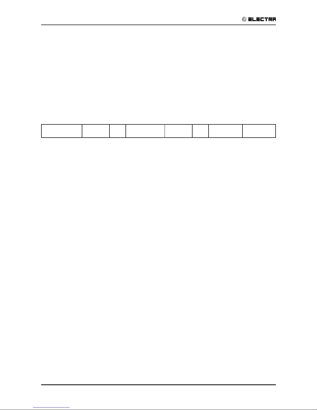
1.11.1 R410A
OUTDOOR UNITS
INDOOR UNITS
MODEL REFRIGER. WNG7 WNG9 WNG12 WNG14 K9 K11 K15 PXD9 PXD12 PXD15
ONG7 ST R410A √
ONG9 ST R410A √ √ √
ONG12 ST R410A √ √ √
ONG14 ST R410A √ √ √
ONG7 RC R410A √
ONG9 RC R410A √ √ √*
ONG12 RC R410A √ √
ONG14 RC R410A √* √
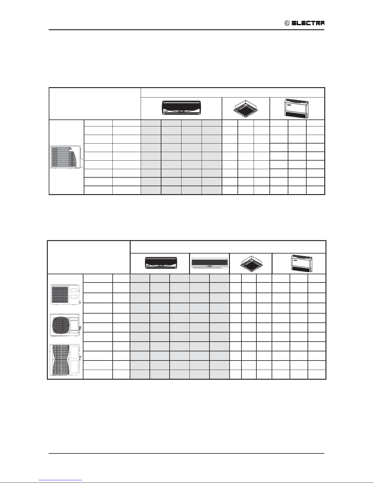
OUTDOOR UNITS
INDOOR UNITS
MODEL REF’ WNG18 WNG21 WNG24 WNG30 WNG36 K18 KN24 KN30 PXD18 PXD24 PXD30
GC18 ST R410A √ √ √
GC21 ST R410A √
GC24 ST R410A √ √ √
OU8 30 ST R410A √ √ √
OU10 36 ST R410A √
GC18 RC R410A √ √ √
GC21 RC R410A √
GC24 RC R410A √
OU8 30 RC R410A √
OU10 36 RC R410A √
√* - The outdoor unit of this combination cannot be matched to other indoor units.
Page 8
1-5
INTRODUCTION
Revision Y05-03
Service Manual - WNG
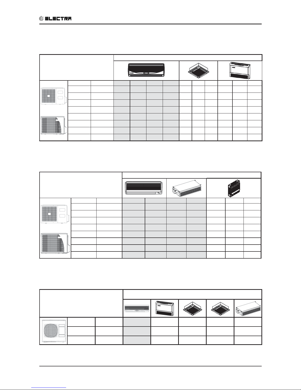
1.11.2 R407C
OUTDOOR UNITS
INDOOR UNITS
MODEL REF’ WNG7 WNG9 WNG12 WNG14 K9 K11 K15 PXD9 PXD12 PXD15
GCN7 ST R407C √
GCN7 RC R407C √
ONG9 ST R407C √ √ √
ONG12 ST R407C √ √ √
ONG14 ST R407C √ √ √
ONG9 RC R407C √ √ √
ONG12 RC R407C √ √ √
ONG14 RC R407C √ √ √
OUTDOOR UNITS
INDOOR UNITS
MODEL REF’ WMN/Z 7 WMN 14 LS 035 LS 040 WMF 7 WMF 9 WMF 12
GCN7 ST R407C √ √
GCN7 RC R407C √ √ √
ONG9 ST R407C √
ONG12 ST R407C √ √
ONG14 ST R407C √ √
ONG9 RC R407C
ONG12 RC
R407C √ √
ONG14 RC
R407C √ √
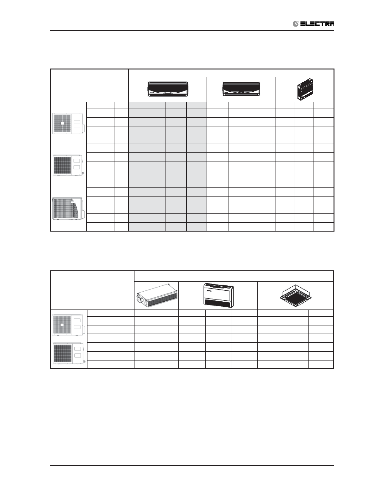
OUTDOOR UNITS
INDOOR UNITS
MODEL REF’ WNG 30 PXD 30 K 30 KN 30 LS 090
OU8 33 ST R407C √ √ √ √ √
OU8 33 RC R407C √ √ √ √ √
Page 9
1-6
INTRODUCTION
Revision Y05-03
Service Manual - WNG
1.11.3 R22
OUTDOOR UNITS
INDOOR UNITS
MODEL REF’ WNG7 WNG9 WNG12 WNG14 WMN/Z7 WMN/Z9 WMN/Z12 WMF7 WMF9 WMF12
GCN7 ST
R22 √* √ √
GCN7 RC
R22 √* √ √
GCN9 ST
R22 √ √ √
GCN9 RC
R22 √* √ √
GCN12 ST
R22 √ √ √
GCN12 RC
R22 √* √ √
GC14 ST
R22 √*
GC14 RC
R22 √*
ONG9 ST
R22 √*
ONG9 RC
R22 √*
ONG12 ST
R22 √*
ONG12 RC
R22 √*
ONG14 ST
R22 √*
ONG14 RC
R22 √*
OUTDOOR UNITS
INDOOR UNITS
MODEL REF’ LSO40 PXD9 PXD12 PXD15 K9 K11 K15
GCN9 ST
R22 √ √
GCN9 RC
R22 √ √
GCN12 ST
R22 √
GCN12 RC
R22 √
GC14 ST
R22 √ √ √
GC14 RC
R22 √ √ √
√* - the outdoor unit of this combination cannot be matched to other indoor units.
Page 10

1-7
INTRODUCTION
Revision Y05-03
Service Manual - WNG
OUTDOOR UNITS
INDOOR UNITS
MODEL REF’ WNG24 WNG30 WMN24 K24 K30 PXD24 PXD30 KN24 KN30 LS065 LS090
GC24 ST R22 √ √ √ √ √ √
GC24 RC R22 √ √ √ √ √ √
GC30 ST R22 √ √ √ √
GC30 RC R22 √ √ √ √
OU8 33 ST R22 √ √ √ √ √ √
OU8 33 RC R22 √ √ √ √ √ √
The above table lists outdoor units and WNG indoor units which can be matched together. In addition the
listed outdoor units can be matched with other types of indoor units such as cassettes, floor/ceiling.
For further information please refer to the relevant Service Manual.
Page 11
2-1
PRODUCT DATA SHEET
Revision Y05-03
Service Manual - WNG
2. PRODUCT DATA SHEET
2.1 R410A
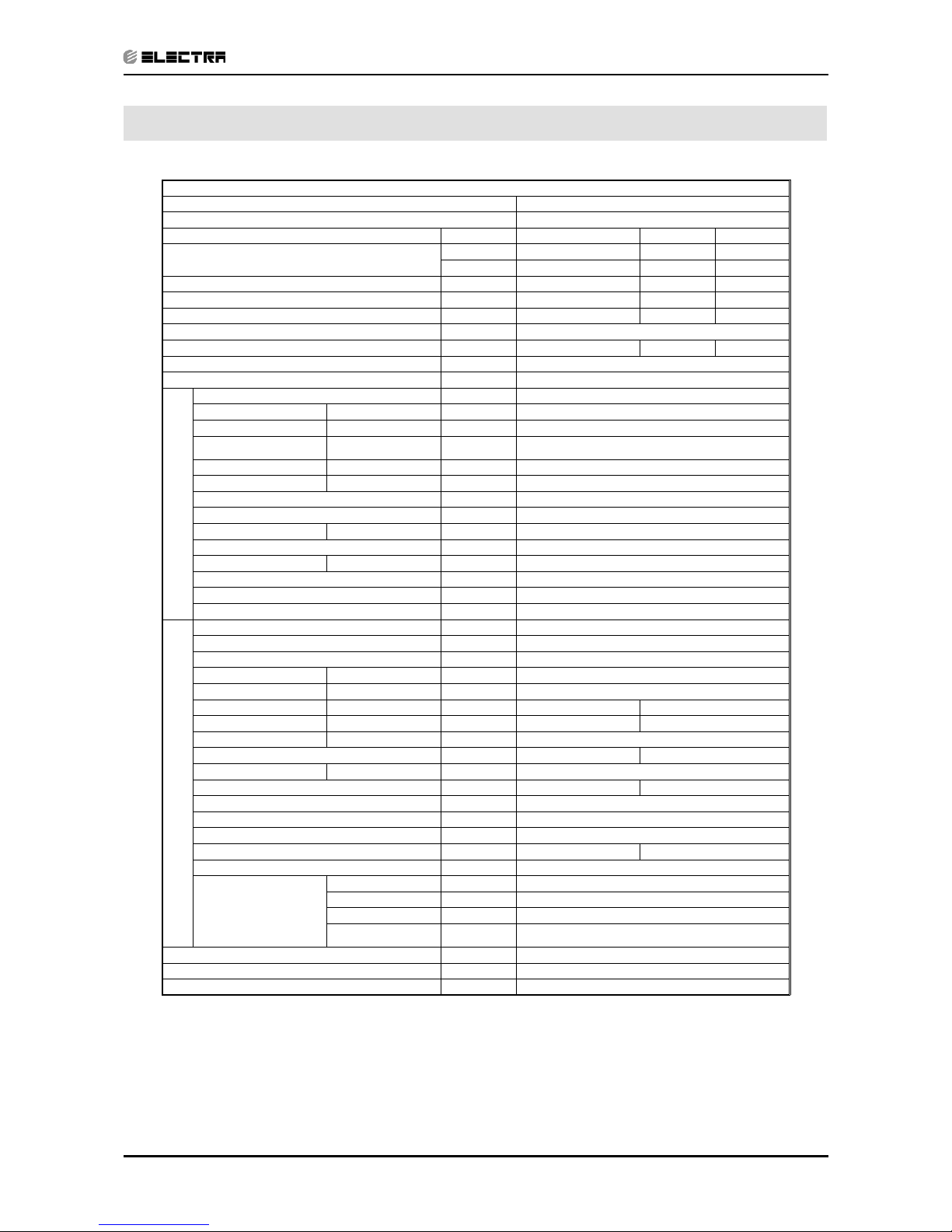
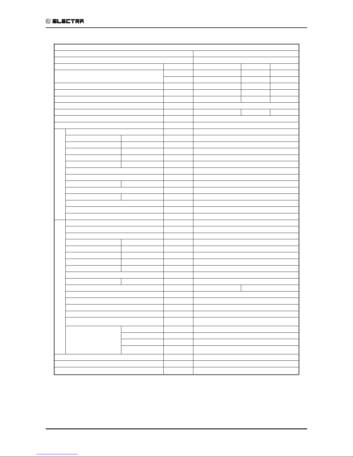
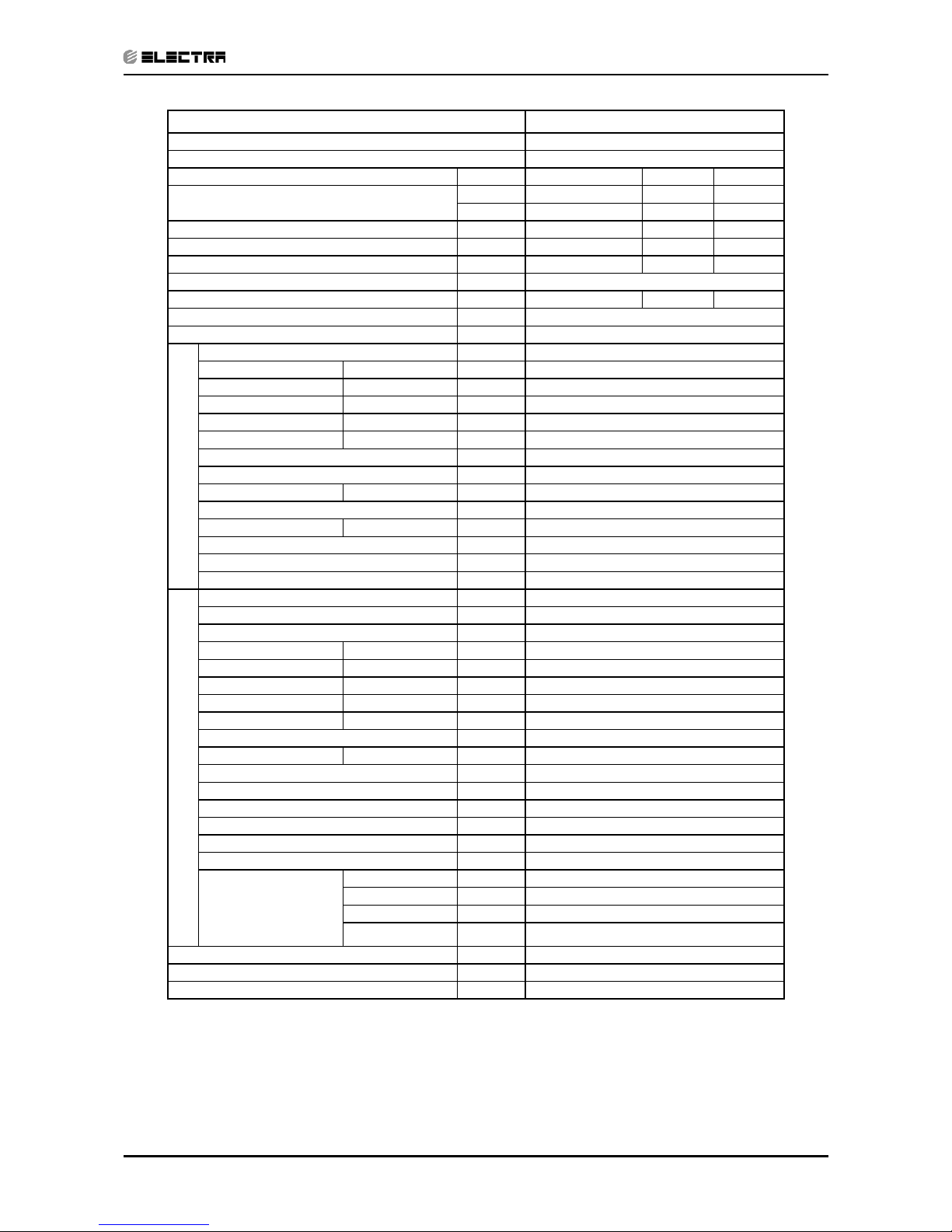
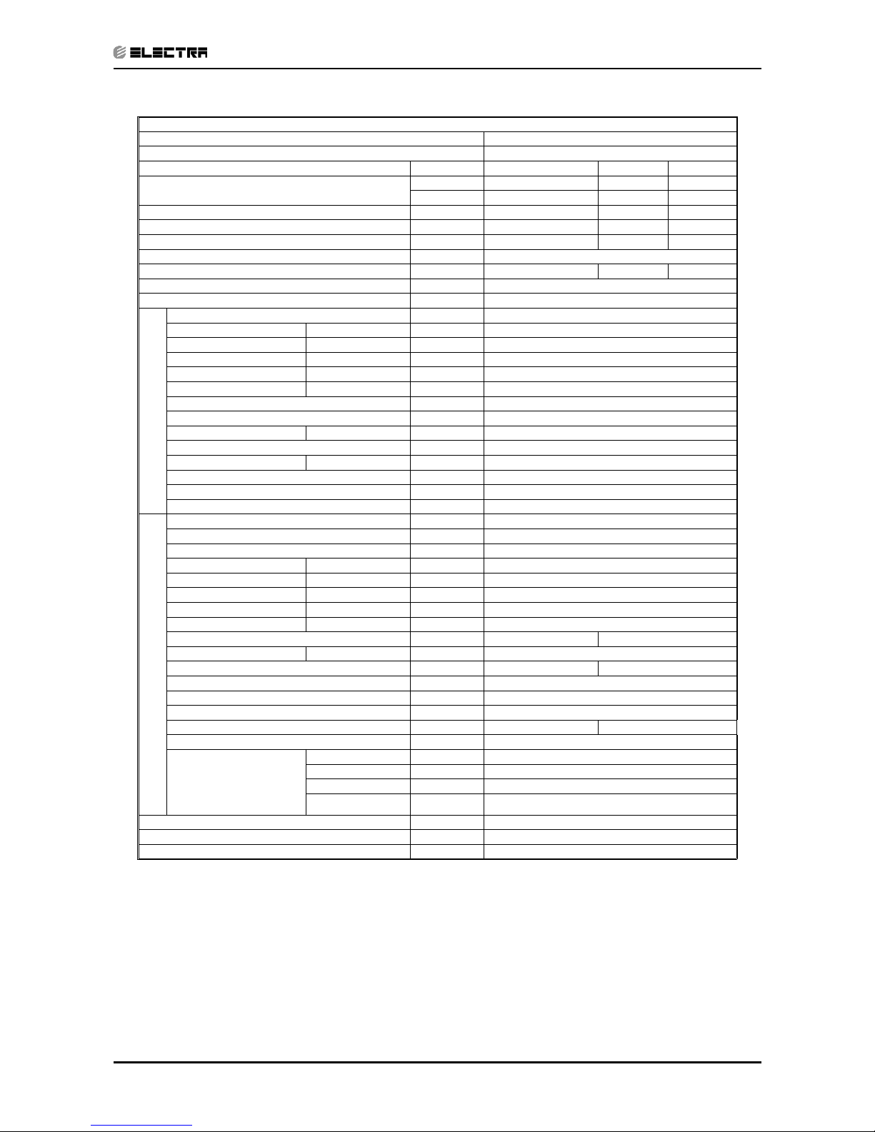
Model Indoor Unit WNG-7
Model Outdoor Unit ONG-7
Installation Method of Pipe Flared
Characteristics Units Cooling Only Cooling Heating
Capacity
(1)
Btu/hr 7610 7610 7760
kW 2.23 2.23 2.28
Power input
(1)
kW 0.68 0.68 0.665
EER (Cooling) or COP(Heating)
(1)
W/W 3.28 3.28 3.42
Energy efficiency class
A
AB
Power supply V/Ph/Hz 220-240V/Single/50Hz
Rated current A 3.0 3.0 2.9
Starting current A 15
Circuit breaker rating A 10
INDOOR
Fan type & quantity Crossflow x 1
Fan speeds H/M/L RPM 860/760/660
Air flow
(2)
H/M/L m3/hr 380/320/280
External static
pressure
Min-Max Pa 0
Sound power level
(3)
H/M/L dB(A) 45/41/39
Sound pressure level
(4)
H/M/L dB(A) 30/27/25
Moisture removal l/hr 0.7
Condenstate drain tube I.D mm 16
Dimensions WxHxD mm 810x190x285
Weight kg 11
Package dimensions WxHxD mm 885x360x285
Packaged weight kg 13.5
Units per pallet units 32
Stacking height units 8 levels
OUTDOOR
Refrigerant control Capillary tube (with 026 restrictor)
Compressor type,model Rotary,LG GK086PAE
Fan type & quantity Propeller(direct) x 1
Fan speeds H/L RPM 680
Air flow H/L m3/hr 1660
Sound power level H/L dB(A) 56 57
Sound pressure level
(4)
H/L dB(A) 46 47
Dimensions WxHxD mm 795x290x610
Weight kg 31 32
Package dimensions WxHxD mm 945x395x655
Packaged weight kg 35 36
Units per pallet Units 9
Stacking height units 3 levels
Refrigerant type R410A
Refrigerant chargless distance kg/m 0.77kg/7.5m 0.89kg/7.5m
Additional charge per 1 meter g/m 15
Connections between
units
Liquid line In.(mm) 1/4”(6.35)
Suction line In.(mm) 3/8”(9.53)
Max.tubing length m. Max.15
Max.height
difference
m. Max.7
Operation control type Remote control
Heating elements (Option) kW 0.3
Others
(1)
Rating conditions in accordance with ISO 5151, ISO 13253 (for ducted units) and EN 14511.
(2)
Airflow in ducted units; at nominal external static pressure.
(3)
Sound power in ducted units is measured at air discharge.
(4)
Sound pressure level measured at 1 meter distance from unit.
Page 12

2-2
PRODUCT DATA SHEET
Revision Y05-03 Service Manual - WNG
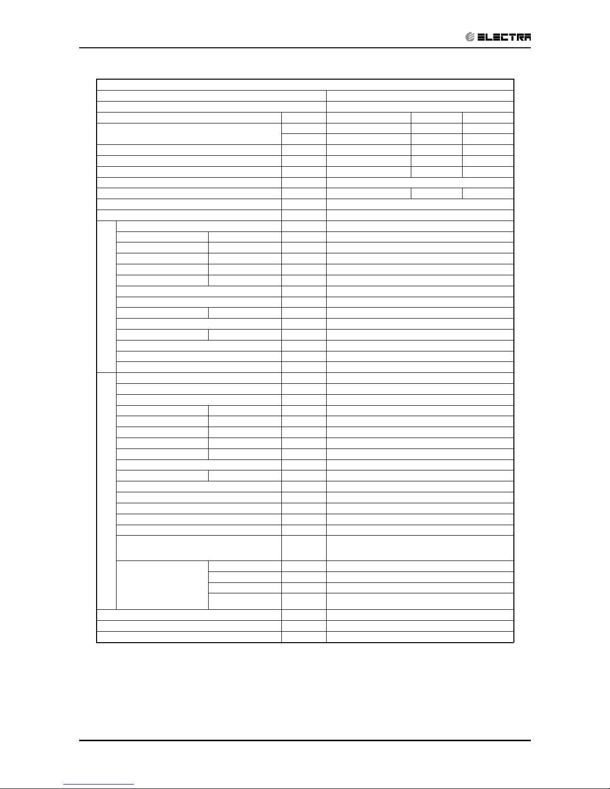
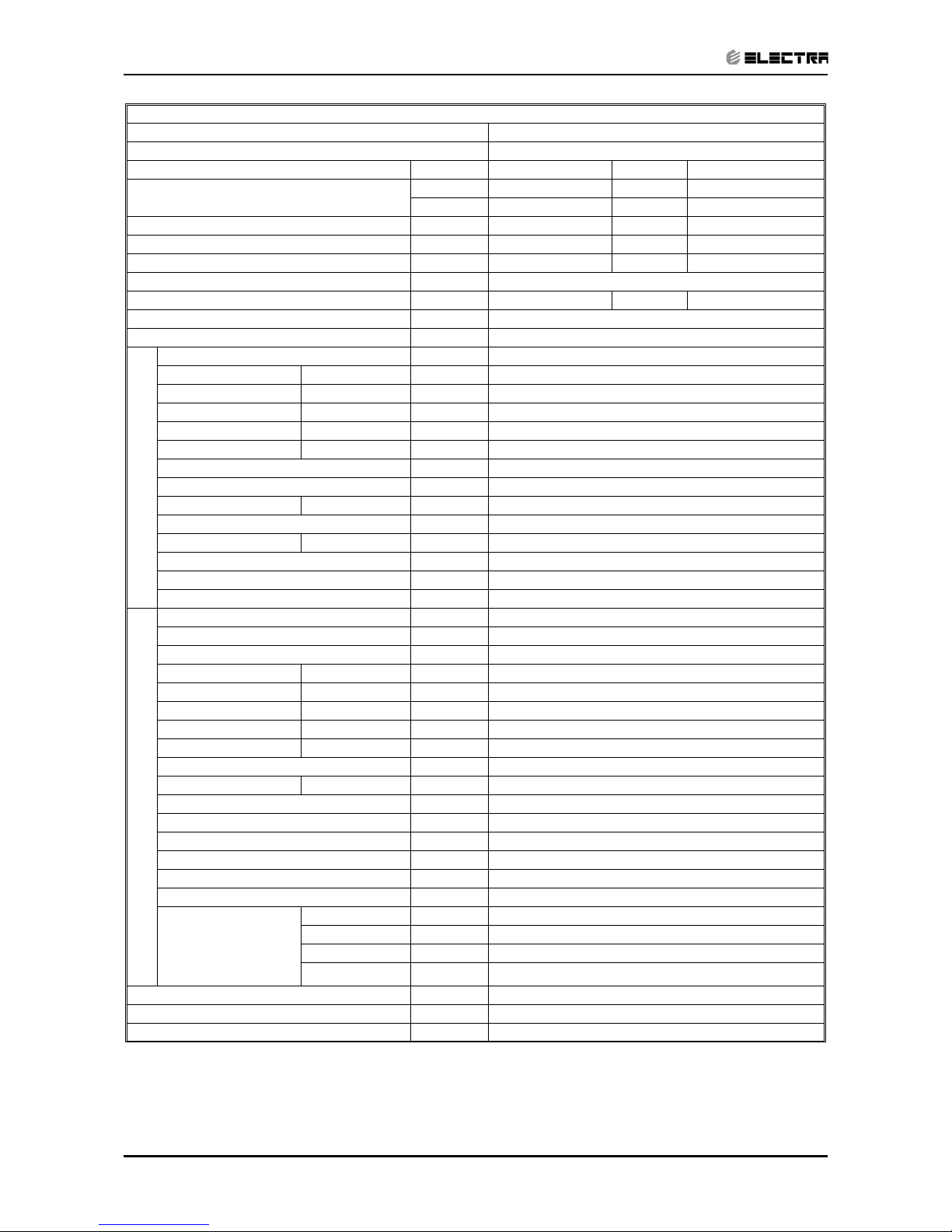
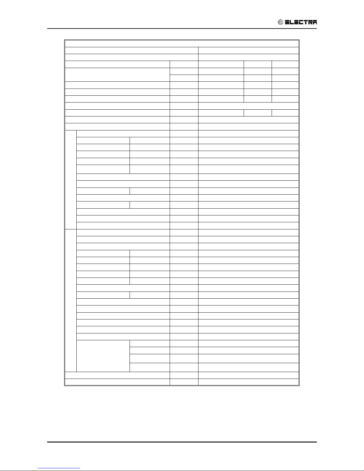
Model Indoor Unit WNG-9
Model Outdoor Unit ONG-9
Installation Method of Pipe Flared
Characteristics Units Cooling Only Cooling Heating
Capacity
(1)
Btu/hr 9280 9280 10240
kW 2.72 2.72 3.0
Power input
(1)
kW 0.825 0.825 0.850
EER (Cooling) or COP(Heating)
(1)
W/W 3.30 3.30 3.53
Energy efficiency class
A
AB
Power supply V/Ph/Hz 220-240V/Single/50Hz
Rated current A 3.7 3.7 3.8
Starting current A 18.7
Circuit breaker rating A 10
INDOOR
Fan type & quantity Crossflow x 1
Fan speeds H/M/L RPM 960/860/760
Air flow
(2)
H/M/L m3/hr 450/380/330
External static pressure Min-Max Pa 0
Sound power level
(3)
H/M/L dB(A) 49/46/44
Sound pressure level
(4)
H/M/L dB(A) 35/31/28
Moisture removal l/hr 0.9
Condenstate drain tube I.D mm 16
Dimensions WxHxD mm 810x190x285
Weight kg 11
Package dimensions WxHxD mm 885x285x360
Packaged weight kg 13.5
Units per pallet units 32
Stacking height units 8 levels
OUTDOOR
Refrigerant control Capillary tube (with 029 restrictor)
Compressor type,model Rotary,LG GK113PAG
Fan type & quantity Propeller(direct) x 1
Fan speeds H/L RPM 780
Air flow H/L m3/hr 1780
Sound power level H/L dB(A) 58 60
Sound pressure level
(4)
H/L dB(A) 48 49
Dimensions WxHxD mm 795x290x610
Weight kg 34 35
Package dimensions WxHxD mm 945x395x655
Packaged weight kg 38 39
Units per pallet Units 9
Stacking height units 3 levels
Refrigerant type R410A
Refrigerant chargless distance kg/m 0.96kg/7.5m 1kg/7.5m
Additional charge per 1 meter g/m 10
Connections between
units
Liquid line In.(mm) 1/4”(6.35)
Suction line In.(mm) 3/8”(9.53)
Max.tubing length m. Max.15
Max.height
difference
m. Max.7
Operation control type Remote control
Heating elements (Option) kW 0.3
Others
(1)
Rating conditions in accordance with ISO 5151, ISO 13253 (for ducted units) and EN 14511.
(2)
Airflow in ducted units; at nominal external static pressure.
(3)
Sound power in ducted units is measured at air discharge.
(4)
Sound pressure level measured at 1 meter distance from unit.
Page 13

2-3
PRODUCT DATA SHEET
Revision Y05-03
Service Manual - WNG
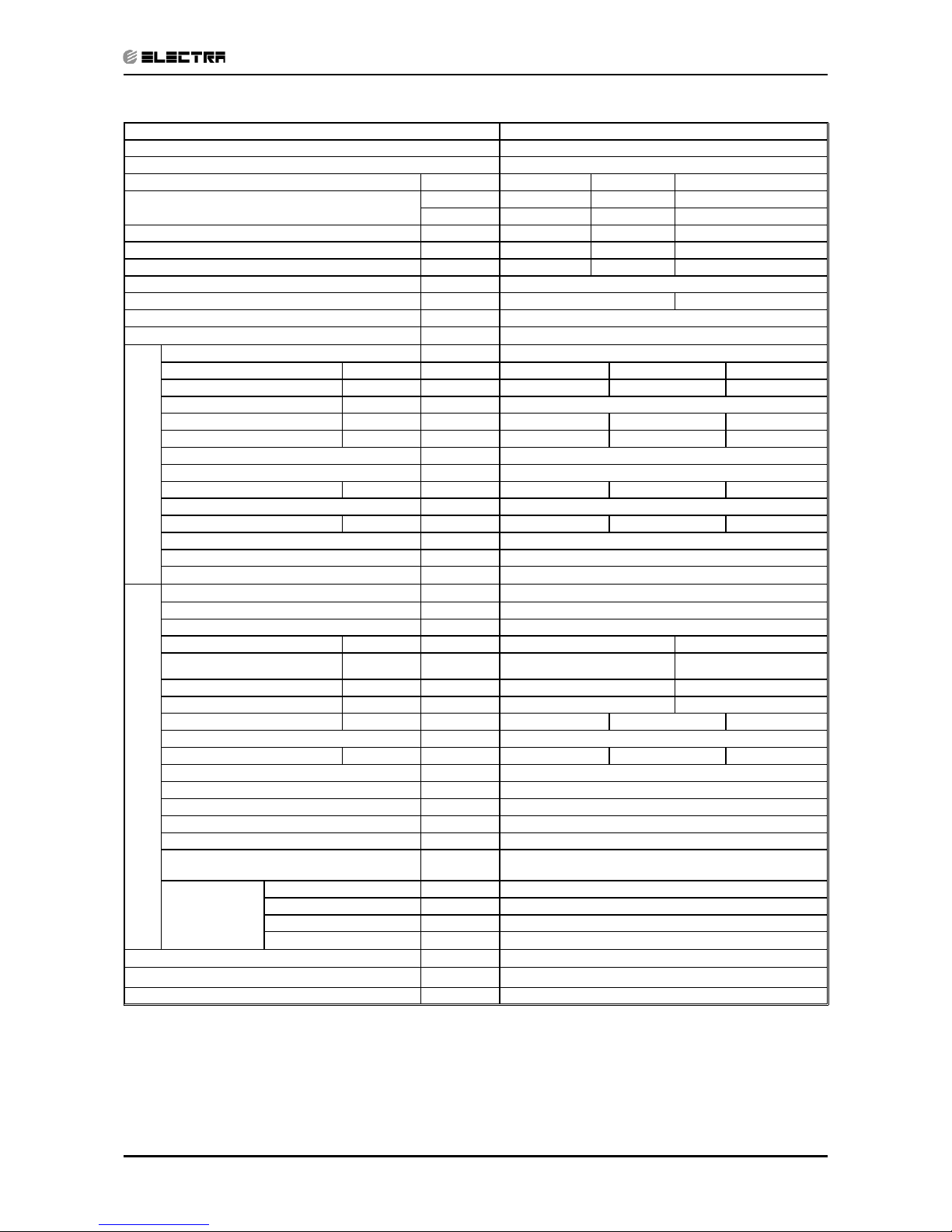
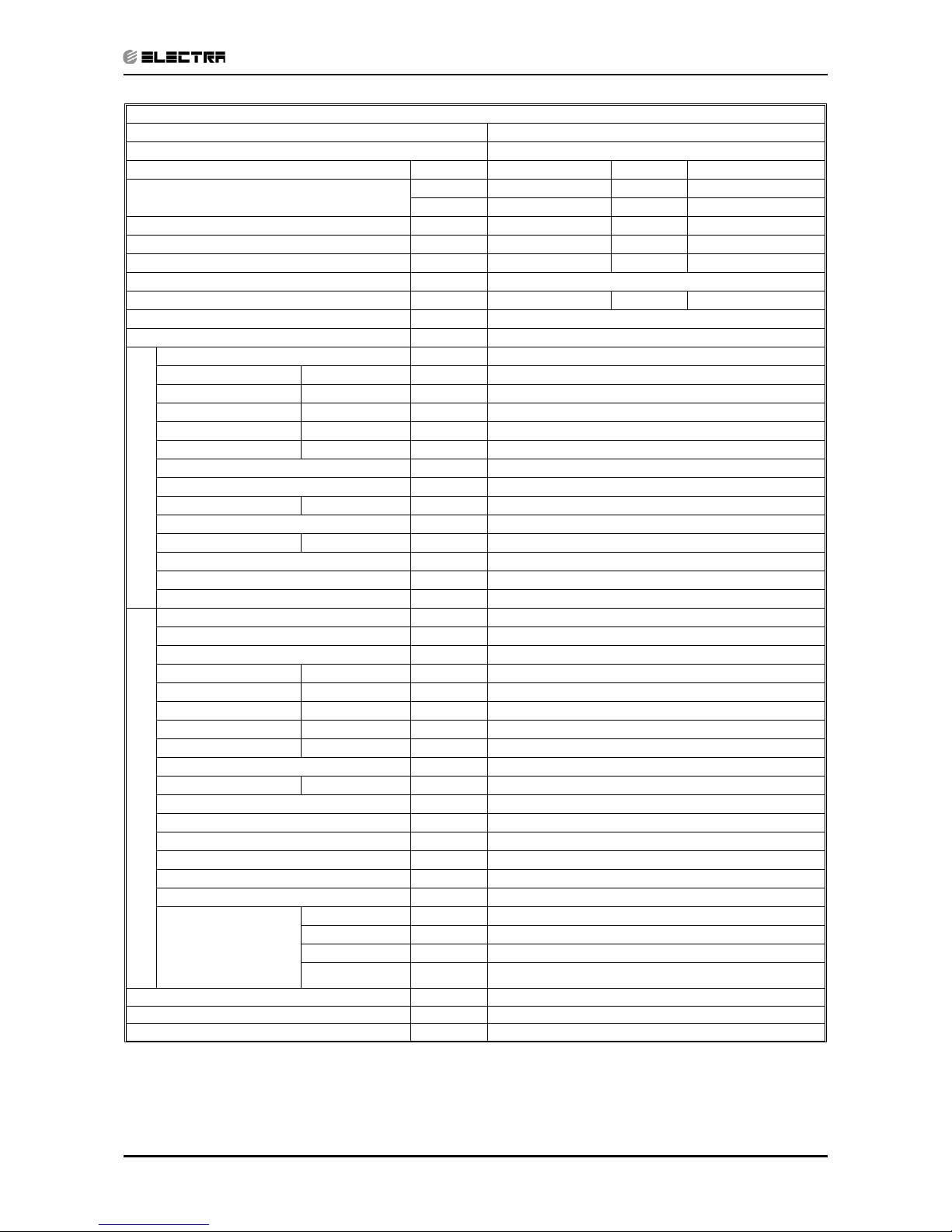
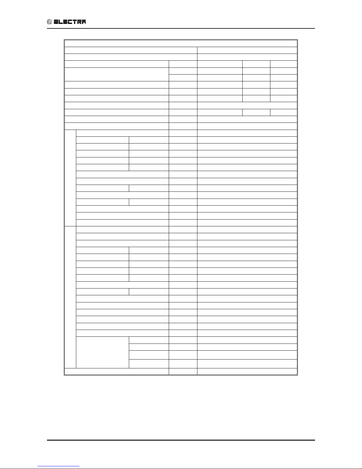
Model Indoor Unit WNG-12
Model Outdoor Unit ONG-12
Installation Method of Pipe Flared
Characteristics Units Cooling Only Cooling Heating
Capacity
(1)
Btu/hr 12390 12390 13650
kW 3.63 3.63 4.0
Power input
(1)
kW 1.115 1.115 1.14
EER (Cooling) or COP(Heating)
(1)
W/W 3.26 3.26 3.51
Energy efficiency class
A
AB
Power supply V/Ph/Hz 220-240V/Single/50Hz
Rated current A 5.0 5.0 5.1
Starting current A 25
Circuit breaker rating A 15
INDOOR
Fan type & quantity Crossflow x 1
Fan speeds H/M/L RPM 1230/1080/930
Air flow
(2)
H/M/L m3/hr 635/550/450
External static pressure Min-Max Pa 0
Sound power level
(3)
H/M/L dB(A) 55/53/49
Sound pressure level
(4)
H/M/L dB(A) 43/39/35
Moisture removal l/hr 1.3
Condenstate drain tube I.D mm 16
Dimensions WxHxD mm 810x190x285
Weight kg 11.5
Package dimensions WxHxD mm 885x360x285
Packaged weight kg 13.5
Units per pallet units 32
Stacking height units 8 levels
OUTDOOR
Refrigerant control Capillary tube
Compressor type,model Rotary,PA145X2C-4FT
Fan type & quantity Propeller(direct) x 1
Fan speeds H/L RPM 810
Air flow H/L m3/hr 1850
Sound power level H/L dB(A) 62 64
Sound pressure level(4) H/L dB(A) 52 53
Dimensions WxHxD mm 795x290x610
Weight kg 35 36
Package dimensions WxHxD mm 945x395x655
Packaged weight kg 39 40
Units per pallet Units 9
Stacking height units 3 levels
Refrigerant type R410A
Refrigerant chargless distance kg/m 1.15kg/7.5m 1.15kg/7.5m
Additional charge per 1 meter g/m 12
Connections between
units
Liquid line In.(mm) 1/4”(6.35)
Suction line In.(mm) 3/8”(9.53)
Max.tubing length m. Max.15
Max.height
difference
m. Max.7
Operation control type Remote control
Heating elements (Option) kW 0.3
Others
(1)
Rating conditions in accordance with ISO 5151, ISO 13253 (for ducted units) and EN 14511.
(2)
Airflow in ducted units; at nominal external static pressure.
(3)
Sound power in ducted units is measured at air discharge.
(4)
Sound pressure level measured at 1 meter distance from unit.
Page 14

2-4
PRODUCT DATA SHEET
Revision Y05-03 Service Manual - WNG
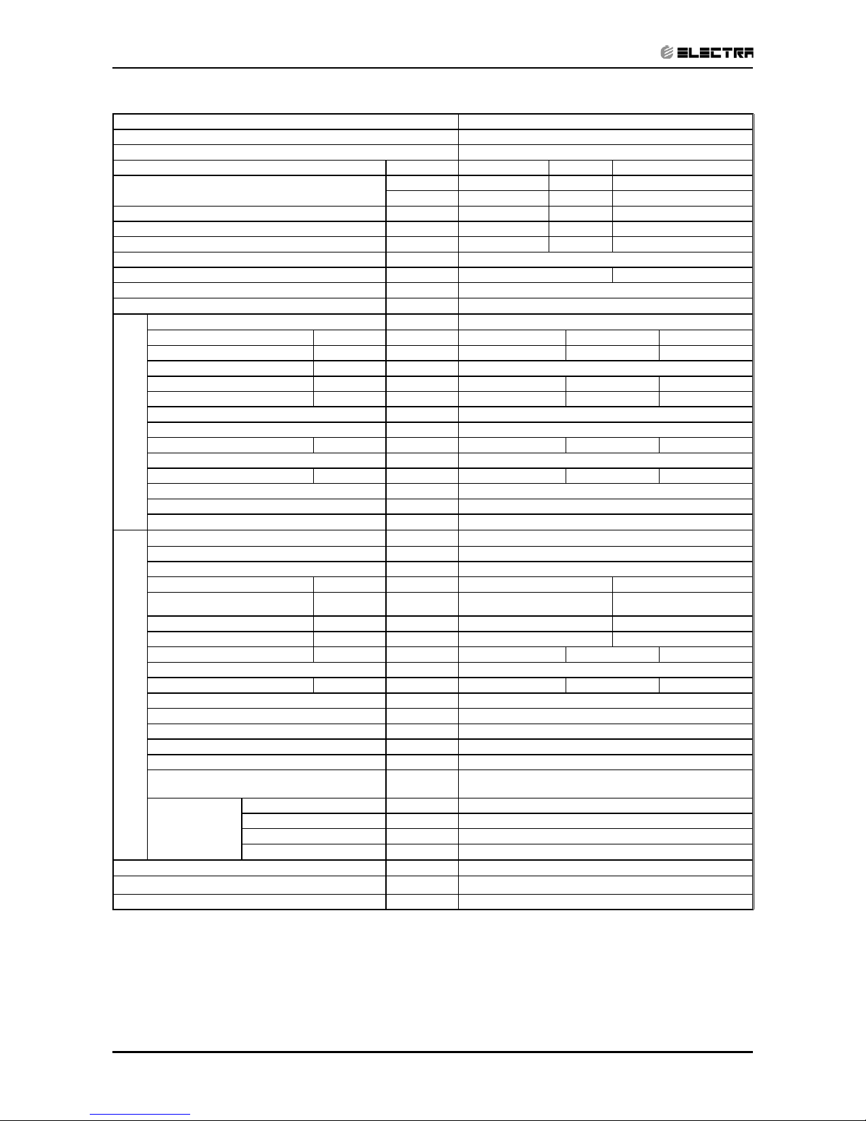
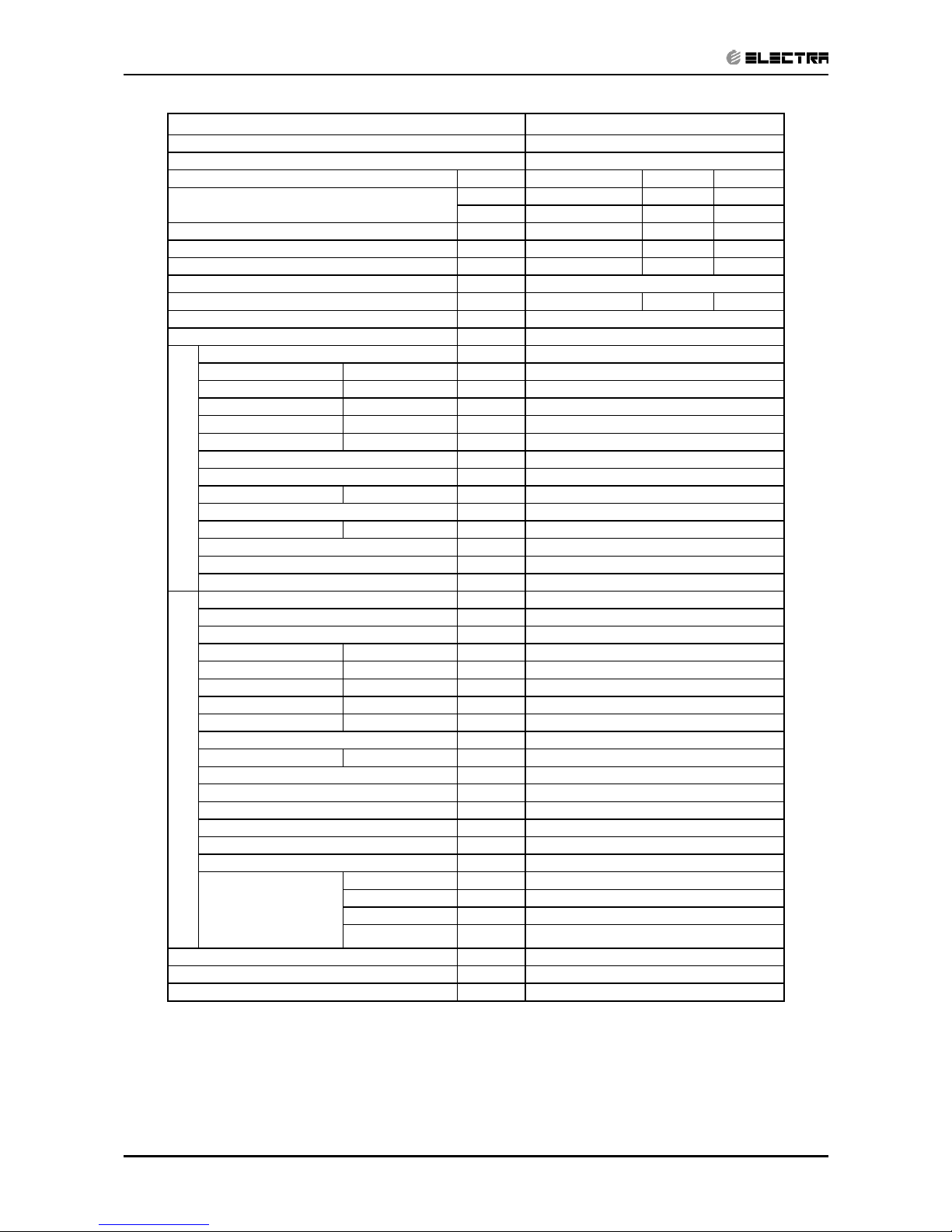
Model Indoor Unit WNG-14
Model Outdoor Unit ONG-14
Installation Method of Pipe Flared
Characteristics Units Cooling Only Cooling Heating
Capacity
(1)
Btu/hr 13650 13650 15290
kW 4.0 4.0 4.48
Power input
(1)
kW 1.33 1.33 1.395
EER (Cooling) or COP(Heating)
(1)
W/W 3.01 3.01 3.21
Energy efficiency class
B
BC
Power supply V/Ph/Hz 220-240V/Single/50Hz
Rated current A 6.1 6.1 6.5
Starting current A 30
Circuit breaker rating A 15
INDOOR
Fan type & quantity Crossflow x 1
Fan speeds H/M/L RPM 1280/1080/930
Air flow
(2)
H/M/L m3/hr 660/550/475
External static pressure Min-Max Pa 0
Sound power level
(3)
H/M/L dB(A) 56/51/46
Sound pressure level
(4)
H/M/L dB(A) 46/41/36
Moisture removal l/hr 1.5
Condenstate drain tube I.D mm 16
Dimensions WxHxD mm 810x190x285
Weight kg 11.5
Package dimensions WxHxD mm 885x360x285
Packaged weight kg 14
Units per pallet units 32
Stacking height units 8 levels
OUTDOOR
Refrigerant control Capillary tube
Compressor type,model Rotary,RN165VHSMT
Fan type & quantity Propeller(direct) x 1
Fan speeds H/L RPM 920
Air flow H/L m3/hr 2160
Sound power level H/L dB(A) 63 64
Sound pressure level
(3)
H/L dB(A) 53 54
Dimensions WxHxD mm 795x290x610
Weight kg 41.5 42.2
Package dimensions WxHxD mm 945x395x655
Packaged weight kg 45.5 46.5
Units per pallet Units 9
Stacking height units 3 levels
Refrigerant type R410A
Refrigerant chargless distance kg/m 1.34kg/7.5m
Additional charge per 1 meter g/m 20
Connections between
units
Liquid line In.(mm) 1/4”(6.35)
Suction line In.(mm) 1/2”(12.7)
Max.tubing length m. Max.15
Max.height
difference
m. Max.7
Operation control type Remote control
Heating elements (Option) kW 0.3
Others
(1)
Rating conditions in accordance with ISO 5151, ISO 13253 (for ducted units) and EN 14511.
(2)
Airflow in ducted units; at nominal external static pressure.
(3)
Sound power in ducted units is measured at air discharge.
(4)
Sound pressure level measured at 1 meter distance from unit.
Page 15

2-5
PRODUCT DATA SHEET
Revision Y05-03
Service Manual - WNG
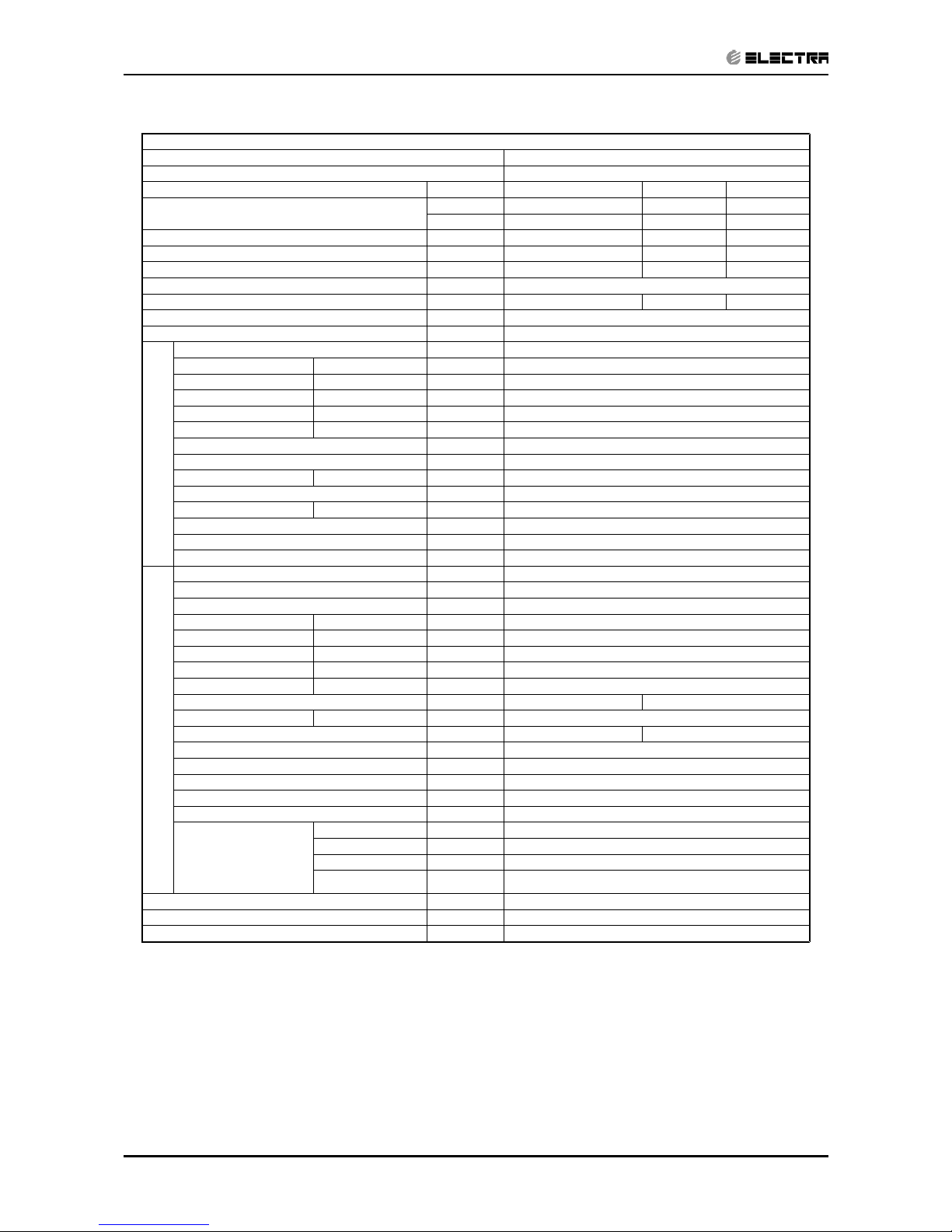
Model Indoor Unit WNG-18
Model Outdoor Unit GC-18
Installation Method of Pipe Flared
Characteristics Units Cooling Only Cooling Heating
Capacity (4)
Btu/hr 18250 18250 18420
kW 5.35 5.35 5.40
Power input (4) kW 1.66 1.66 1.56
EER (Cooling) or COP(Heating) (4) W/W 3.22 3.22 3.46
Energy efficiency class
A
AB
Power supply V/Hz/Ph 220-240V/50Hz/Single
Rated current A 7.5 7.5 7.1
Starting current A 43
Circuit breaker rating A 15
INDOOR
Fan type & quantity Cross flow*1
Fan speeds H/M/L RPM 1200/1100/1000
Air flow (1) H/M/L m3/hr 930/840/750
External static pressure Min-Max Pa N/A
Sound power level (2) H/M/L dB(A) 56-53-50
Sound pressure level(3) H/M/L dB(A) 43-40-37
Moisture removal l/hr 1.8
Condenstate drain tube I.D mm 16
Dimensions WxHxD mm 1060x295x210
Weight kg 14
Package dimensions WxHxD mm 1115x350x260
Packaged weight kg 17
Units per pallet units 16
Stacking height units 8
OUTDOOR
Refrigerant control Capillary tube
Compressor type,model Rotary,TOSHIBA PA200X2CS-4KU1
Fan type & quantity Propeller(direct) x 1
Fan speeds H/L RPM 815
Air flow H/L m3/hr 2480
Sound power level H/L dB(A) 68
Sound pressure level(3) H/L dB(A) 57
Dimensions WxHxD mm 846*302*690
Weight kg 56
Package dimensions WxHxD mm 990*430*770
Packaged weight kg 61
Units per pallet Units 9
Stacking height units 3
Refrigerant type R410A
Refrigerant chargless distance kg/m 1.54kg/7.5m
Additional charge g/m
4m≤Length≤10m 1540g 10m≤Length≤18m 1690g
18m≤Length≤25m 1900g
Connections between
units
Liquid line In.(mm) 1/4”(6.35)
Suction line In.(mm) 1/2”(12.7)
Max.tubing length m. 25
Max.height
difference
m. 15
Operation control type Remote control
Heating elements kW
Others All season kit Factory option
(1)
Rating conditions in accordance with ISO 5151, ISO 13253 (for ducted units) and EN 14511.
(2)
Airflow in ducted units; at nominal external static pressure.
(3)
Sound power in ducted units is measured at air discharge.
(4)
Sound pressure level measured at 1 meter distance from unit.
Page 16
2-6
PRODUCT DATA SHEET
Revision Y05-03 Service Manual - WNG
Model Indoor Unit WNG 21
Model Outdoor Unit GC 21
Installation Method of Pipe Flared
Characteristics Units Cooling Only Cooling Heating
Capacity
(1)
Btu/hr 21150 21150 22180
kW 6.2 6.2 6.50
Power input
(1)
kW 2.05 2.05 2.00
EER (Cooling) or COP(Heating)
(1)
W/W 3.02 3.02 3.25
Energy efficiency class
BB
C
Power supply V/Ph/Hz 220-240V/Single/50Hz
Rated current A 9.3 9.3 9.1
Starting current A 50
Circuit breaker rating A 20
INDOOR
Fan type & quantity Cross flow x 1
Fan speeds H/M/L RPM 1300/1200/1100
Air flow
(2)
H/M/L m3/hr 910/820/740
External static pressure Min-Max Pa 0
Sound power level
(3)
H/M/L dB(A) 60/57/55
Sound pressure level
(4)
H/M/L dB(A) 47/44/42
Moisture removal l/hr 2.3
Condensate drain tube I.D mm 16
Dimensions WxHxD mm 1060x295x210
Weight kg 15
Package dimensions WxHxD mm 1125x360x280
Packaged weight kg 18
Units per pallet units 16
Stacking height units 8 levels
OUTDOOR
Refrigerant control Capillary tube
Compressor type, model Rotary ,TOSHIBA PA240X2CS-4KU1
Fan type & quantity Propeller(direct) x 1
Fan speeds H/L RPM 815
Air flow H/L m3/hr 2860
Sound power level H/L dB(A) 69
Sound pressure level
(4)
H/L dB(A) 59
Dimensions WxHxD mm 846X690x302
Weight kg 56
Package dimensions WxHxD mm 990x720x430
Packaged weight kg 61
Units per pallet Units 9
Stacking height units 3 levels
Refrigerant type R410A
Refrigerant chargless distance kg/m 2/7.5m
Additional charge per 1 meter g/m
4m≤ L ≤10m:+0g
10m≤ L ≤15m:+330g
15m≤ L ≤20m:+460g
Connections between
units
Liquid line In.(mm) 3/8”(9.53)
Suction line In.(mm) 5/8”(15.88)
Max. tubing length m. Max.20
Max. height
difference
m. Max.15
Operation control type Remote control
Heating Elements kW 1.65/0.9
Others
(1)
Rating conditions in accordance with ISO 5151, ISO 13253 (for ducted units) and EN 14511.
(2)
Airflow in ducted units; at nominal external static pressure.
(3)
Sound power in ducted units is measured at air discharge.
(4)
Sound pressure level measured at 1 meter distance from unit
Page 17
2-7
PRODUCT DATA SHEET
Revision Y05-03
Service Manual - WNG
Model Indoor Unit WNG 24
Model Outdoor Unit OU7-24
Installation method WALL MOUNTED
Characteristics Units Cooling only Cooling Heating
Capacity (1)
Btu/hr 23100 23100 24150
kW 6.77 6.77 7.08
Power input (1) kW 2.24 2.24 2.4
COP (1) W/W 3.02 3.02 3.01
Energy efficiency class B B D
Power supply V/ Ph /Hz 230/50/1
Rated current A 9.3 10.2
Starting current A 63
Circuit breaker rating A 20
INDOOR
Fan type & quantity CROSS FLOW *1
Fan speeds H/ M/ L RPM 1300 1200 1100
Air flow (2) H/ M/ L m³/hr 910 820 740
External static pressure Min-Max Pa N/A
Sound power level (3) H/ M/ L dB(A) 60 57 55
Sound pressure level (4) H/ M/ L dB(A) 47 44 42
Moisture removal L/hr 2.3
Condensate drain tube I.D mm 16
Dimensions W/ H / D mm 1060 295 210
Weight kg 15
Package dimensions W/ H / D mm 1125 360 280
Packaged weight kg 18
Units per pallet Units 16
Stacking height Units 8
OUTDOOR
Refrigerant control CAPILLARY TUBE
Compressor type, model ROTARY
Fan type & quantity AXIAL*1
Fan speeds H / L RPM 850 720
Air flow H / L m³/hr 3100 2600
Sound power level H / L
dB(A)
67 62
Sound pressure level (4) H / L
dB(A)
58 54
Dimensions W/ H / D mm 900 680 340
Weight kg 74
Package dimensions W/ H / D mm 985 730 406
Packaged weight kg 77
Units per pallet Units 6
Stacking height Units 2
Refrigerant type R410A
Refrigerant chargless distance kg/m 2.035/12.5
Additional charge g/m
12.5m<Add 350g<15m
15m<Add 1040g<20m
Connections
between units
Liquid line In. 3/8
Suction line In. 5/8
Max. tubing length m. 20
Max. height difference m. 15
Operation control type LCD REMOTE CONTROL
Heating elements kW
Others All season kit Factory option
(1)
Rating conditions in accordance with ISO 5151, ISO 13253 (for ducted units) and EN 14511.
(2)
Airflow in ducted units; at nominal external static pressure.
(3)
Sound power in ducted units is measured at air discharge.
(4)
Sound pressure level measured at 1 meter distance from unit
Page 18
2-8
PRODUCT DATA SHEET
Revision Y05-03 Service Manual - WNG
Model Indoor Unit WNG 24
Model Outdoor Unit OU7-24T
Installation method WALL MOUNTED
Characteristics Units Cooling only Cooling Heating
Capacity (1)
Btu/hr 23220 23220 25130
kW 6.81 6.81 7.37
Power input (1) kW 2.26 2.26 2.4
COP (1) W/W 3.01 3.01 3.07
Energy efficiency class B B D
Power supply V/ Ph /Hz 400/50/3N
Rated current A 4.1*3 4.4*3
Starting current A 55
Circuit breaker rating A 10*3
INDOOR
Fan type & quantity CROSS FLOW *1
Fan speeds H/ M/ L RPM 1300 1200 1100
Air flow (2) H/ M/ L m³/hr 990 930 840
External static pressure Min-Max Pa N/A
Sound power level (3) H/ M/ L dB(A) 58 55 53
Sound pressure level (4) H/ M/ L dB(A) 45 42 40
Moisture removal L/hr 2.3
Condensate drain tube I.D mm 16
Dimensions W/ H / D mm 1060 295 210
Weight kg 15
Package dimensions W/ H / D mm 1115 350 260
Packaged weight kg 18
Units per pallet Units 16
Stacking height Units 8
OUTDOOR
Refrigerant control CAPILLARY TUBE
Compressor type, model ROTARY
Fan type & quantity AXIAL*1
Fan speeds H / L RPM 850 720
Air flow H / L m³/hr 3100 2600
Sound power level H / L
dB(A)
67 62
Sound pressure level (4) H / L
dB(A)
58 54
Dimensions W/ H / D mm 900 680 340
Weight kg 74
Package dimensions W/ H / D mm 985 730 406
Packaged weight kg 74
Units per pallet Units 6
Stacking height Units 2
Refrigerant type R410A
Refrigerant chargless distance kg/m 2.035/12.5
Additional charge g/m
12.5m<Add 350g<15m
12.5m<Add 1040g<20m
Connections
between units
Liquid line In. 3/8
Suction line In. 5/8
Max. tubing length m. 20
Max. height difference m. 15
Operation control type LCD REMOTE CONTROL
Heating elements kW
Others All season kit Factory option
(1)
Rating conditions in accordance with ISO 5151, ISO 13253 (for ducted units) and EN 14511.
(2)
Airflow in ducted units; at nominal external static pressure.
(3)
Sound power in ducted units is measured at air discharge.
(4)
Sound pressure level measured at 1 meter distance from unit
Page 19
2-9
PRODUCT DATA SHEET
Revision Y05-03
Service Manual - WNG
Model Indoor Unit WNG-25
Model Outdoor Unit GC-24
Installation Method of Pipe Flared
Characteristics Units Cooling Only Cooling Heating
Capacity
(1)
Btu/hr 22960 22960 24570
kW 6.73 6.73 7.2
Power input
(1)
kW 2.34 2.34 2.33
EER (Cooling) or COP(Heating)
(1)
W/W 2.88 2.88 3.09
Energy efficiency class
C
CD
Power supply V/Ph/Hz 220-240V/Single/50Hz
Rated current A 10.3 10.3 10.2
Starting current A 63
Circuit breaker rating A 20
INDOOR
Fan type & quantity Crossflow x 1
Fan speeds H/M/L RPM 1050/930/800
Air flow
(2)
H/M/L m3/hr 1000/850/720
External static pressure Min-Max Pa 0
Sound power level
(3)
H/M/L dB(A) 58/54/51
Sound pressure level
(4)
H/M/L dB(A) 45/42/38
Moisture removal l/hr 2.6
Condenstate drain tube I.D mm 16
Dimensions WxHxD mm 1200X340X236
Weight kg 18.5
Package dimensions WxHxD mm 1305X430X325
Packaged weight kg 25.5
Units per pallet units 12
Stacking height units 6 levels
OUTDOOR
Refrigerant control Capillary tube restrictor for heating)
Compressor type,model Rotary,NN27VBAMT
Fan type & quantity Propeller(direct) x 1
Fan speeds H/L RPM 815
Air flow H/L m3/hr 2860
Sound power level H/L dB(A) 67
Sound pressure level
(4)
H/L dB(A) 58
Dimensions WxHxD mm 846X302X690
Weight kg 56
Package dimensions WxHxD mm 990X430X770
Packaged weight kg 61 63
Units per pallet Units 9
Stacking height units 3 levels
Refrigerant type R410A
Refrigerant chargless distance kg/m 2.18kg/7.5m
Additional charge g/m
4m≤Lin<10m:2180g 10m≤Lin<18m:2330g
18m≤Lin<25m:2550g
Connections between
units
Liquid line In.(mm) 3/8”(9.53)
Suction line In.(mm) 5/8”(15.88)
Max.tubing length m. Max.25
Max.height
difference
m. Max.15
Operation control type Remote control
Heating elements kW
Others
(1)
Rating conditions in accordance with ISO 5151, ISO 13253 (for ducted units) and EN 14511.
(2)
Airflow in ducted units; at nominal external static pressure.
(3)
Sound power in ducted units is measured at air discharge.
(4)
Sound pressure level measured at 1 meter distance from unit.
Page 20
2-10
PRODUCT DATA SHEET
Revision Y05-03 Service Manual - WNG
Model Indoor Unit WNG- 30
Model Outdoor Unit OU8-30 R410A
Installation Method of Pipe Flared
Characteristics Units Cooling Only Cooling Heating
Capacity
(1)
Btu/hr 29000 29000 31800
kW 8.5 8.5 9.08
Power input
(1)
kW 2.92 2.92 2.98
EER (Cooling) or COP(Heating)
(1)
W/W 2.91 2.91 3.05
Energy efficiency class C C D
Power supply V/Ph/Hz 220-240V/Single/50Hz
Rated current A 12.2 12.2 12.1
Starting current A 80
Circuit breaker rating A 25
INDOOR
Fan type & quantity Cross flow x 1
Fan speeds H/M/L RPM 1380/11150/1000
Air flow
(2)
H/M/L m3/hr 1360/1110/1030
External static pressure Min-Max Pa N/A
Sound power level
(3)
H/M/L dB(A) 66/61/57
Sound pressure level
(4)
H/M/L dB(A) 52/48/44
Moisture removal l/hr 3.5
Condensate drain tube I.D mm 16
Dimensions WxHxD mm 1200X340X236
Weight kg 17.0
Package dimensions WxHxD mm 1300/430/315
Packaged weight kg 24.0
Units per pallet units 12
Stacking height units 6 levels
OUTDOOR
Refrigerant control Capillary
Compressor type, model Rotary
Fan type & quantity Axial & 1
Fan speeds H/L RPM 850
Air flow H/L m3/hr 3150
Sound power level H/L dB(A) 69
Sound pressure level
(4)
H/L dB(A) 59
Dimensions WxHxD mm 900X860X340
Weight kg 78
Package dimensions WxHxD mm 985X907X435
Packaged weight kg 82
Units per pallet Units 6
Stacking height units 2 levels
Refrigerant type R410A
Refrigerant charge less distance kg/m 2.42 / 15
Additional charge gr/m 30
Connections between
units
Liquid line In.(mm) 3/8”
Suction line In.(mm) 5/8”
Max.tubing length m. 30
Max.height
difference
m. 15
Operation control type LCD Remote control
Heating elements kW
Others Crankcase heater (50W),
(1)
Rating conditions in accordance with ISO 5151, ISO 13253 (for ducted units) and EN 14511.
(2)
Airflow in ducted units; at nominal external static pressure.
(3)
Sound power in ducted units is measured at air discharge.
(4)
Sound pressure level measured at 1 meter distance from unit.
Page 21
2-11
PRODUCT DATA SHEET
Revision Y05-03
Service Manual - WNG
Model Indoor Unit WNG- 30T
Model Outdoor Unit OU8-30T R410A
Installation Method of Pipe WALL MOUNTED
Characteristics Units Cooling Only Cooling Heating
Capacity
(1)
Btu/hr 29000 29000 31000
kW 8.5 8.5 9.08
Power input
(1)
kW 2.83 2.83 2.98
EER (Cooling) or COP(Heating)
(1)
W/W 3.00 3.00 3.05
Energy efficiency class C C D
Power supply V/Ph/Hz 400V/3PH/50Hz
Rated current A 3X5.6 3X5.6 3X5.8
Starting current A 35
Circuit breaker rating A 3X16
INDOOR
Fan type & quantity Cross flow & 1
Fan speeds H/M/L RPM 1380/1150/1000
Air flow
(2)
H/M/L m3/hr 1360/1110/1030
External static pressure Min-Max Pa N/A
Sound power level
(3)
H/M/L dB(A) 66/61/57
Sound pressure level
(4)
H/M/L dB(A) 52/48/44
Moisture removal l/hr 3.5
Condensate drain tube I.D mm 16
Dimensions WxHxD mm 1200X340X236
Weight kg 17.0
Package dimensions WxHxD mm 1300X430X315
Packaged weight kg 24
Units per pallet units 12
Stacking height units 6 levels
OUTDOOR
Refrigerant control Capillary
Compressor type, model Rotary
Fan type & quantity Axial & 1
Fan speeds H/L RPM 850
Air flow H/L m3/hr 3150
Sound power level H/L dB(A) 69.0
Sound pressure level
(4)
H/L dB(A) 59.0
Dimensions WxHxD mm 900X860X340
Weight kg 78
Package dimensions WxHxD mm 985X907X435
Packaged weight kg 82
Units per pallet Units 6
Stacking height units 2 levels
Refrigerant type R410A
Refrigerant charge less distance kg/m 2.13 / 7.5
Additional charge gr/m 30
Connections between
units
Liquid line In.(mm) 3/8”
Suction line In.(mm) 5/8”
Max.tubing length m. 30
Max.height
difference
m. 15
Operation control type LCD Remote control
Heating elements kW
Others Crankcase heater (50W), 3 Phase Protector
(1)
Rating conditions in accordance with ISO 5151, ISO 13253 (for ducted units) and EN 14511.
(2)
Airflow in ducted units; at nominal external static pressure.
(3)
Sound power in ducted units is measured at air discharge.
(4)
Sound pressure level measured at 1 meter distance from unit.
Page 22
2-12
PRODUCT DATA SHEET
Revision Y05-03 Service Manual - WNG
Model Indoor Unit WNG 36
Model Outdoor Unit OU10-36
Installation Method of Pipe Flared
Characteristics Units Cooling Only Cooling Heating
Capacity
(1)
Btu/hr 34600 34600 38000
kW 10.15 10.15 11.14
Power input
(1)
kW 3.22 3.22 3.60
EER (Cooling) or COP(Heating)
(1)
W/W 3.15 3.15 3.10
Energy efficiency class B B D
Power supply V/Ph/Hz 220-240V/Single/50Hz
Rated current A 15.3 15.3 16.8
Starting current A 92
Circuit breaker rating A 25
INDOOR
Fan type & quantity Cross flow x 1
Fan speeds H/M/L RPM 1380/1270/1150
Air flow
(2)
H/M/L m3/hr 1360/1240/1110
External static pressure Min-Max Pa 0
Sound power level
(3)
H/M/L dB(A) 66/63/61
Sound pressure level
(4)
H/M/L dB(A) 52/50/48
Moisture removal l/hr 4
Condensate drain tube I.D mm 16
Dimensions WxHxD mm 1200x340x236
Weight kg 17
Package dimensions WxHxD mm 1300x430x315
Packaged weight kg 24
Units per pallet units 12 units per pallet
Stacking height units 6 levels
OUTDOOR
Refrigerant control Capillary tube
Compressor type, model Rotary, Mitsubishi Siam NN40VAAMT
Fan type & quantity Propeller(direct) x 2
Fan speeds H/L RPM 1150
Air flow H/L m3/hr 4150
Sound power level H/L dB(A) 70.4
Sound pressure level
(4)
H/L dB(A) 61.1
Dimensions WxHxD mm 900x970x340
Weight kg 87
Package dimensions WxHxD mm 985x1020x435
Packaged weight kg 91
Units per pallet Units 6
Stacking height units 2 levels
Refrigerant type R410A
Refrigerant chargless distance kg/m 2.38kg/15m
Additional charge per 1 meter g/m 30
Connections between
units
Liquid line In.(mm) 3/8”(9.53)
Suction line In.(mm) 3/4”(19.06)
Max. tubing length m. Max.50
Max. height
difference
m. Max.25
Operation control type Remote control
Heating Elements kW
Others Crankcase Heater (50w)
(1)
Rating conditions in accordance with ISO 5151, ISO 13253 (for ducted units) and EN 14511.
(2)
Airflow in ducted units; at nominal external static pressure.
(3)
Sound power in ducted units is measured at air discharge.
(4)
Sound pressure level measured at 1 meter distance from unit
Page 23
2-13
PRODUCT DATA SHEET
Revision Y05-03
Service Manual - WNG
Model Indoor Unit WNG 36
Model Outdoor Unit OU10-36T
Installation Method of Pipe Flared
Characteristics Units Cooling Only Cooling Heating
Capacity
(1)
Btu/hr 35480 35480 38200
kW 10.40 10.40 11.20
Power input
(1)
kW 3.06 3.06 3.40
EER (Cooling) or COP(Heating)
(1)
W/W 3.40 3.40 3.30
Energy efficiency class A A C
Power supply V/Ph/Hz 400V/3/50Hz
Rated current A 3X6.3 3X6.3 3X7.2
Starting current A 43
Circuit breaker rating A 3X16
INDOOR
Fan type & quantity Cross flow x 1
Fan speeds H/M/L RPM 1380/1270/1150
Air flow
(2)
H/M/L m3/hr 1360/1240/1110
External static pressure Min-Max Pa 0
Sound power level
(3)
H/M/L dB(A) 66/63/61
Sound pressure level
(4)
H/M/L dB(A) 52/50/48
Moisture removal l/hr 4
Condensate drain tube I.D mm 16
Dimensions WxHxD mm 1200x340x236
Weight kg 17
Package dimensions WxHxD mm 1300x430x315
Packaged weight kg 24
Units per pallet units 12 units per pallet
Stacking height units 6 levels
OUTDOOR
Refrigerant control Capillary tube
Compressor type, model Rotary, Mitsubishi Siam NN40VCAMT
Fan type & quantity Propeller(direct) x 2
Fan speeds H/L RPM 1150
Air flow H/L m3/hr 4150
Sound power level H/L dB(A) 70.4
Sound pressure level
(4)
H/L dB(A) 61.1
Dimensions WxHxD mm 900x970x340
Weight kg 87
Package dimensions WxHxD mm 985x1020x435
Packaged weight kg 91
Units per pallet Units 6
Stacking height units 2 levels
Refrigerant type R410A
Refrigerant chargless distance kg/m 2.38kg/15m
Additional charge per 1 meter g/m 30
Connections between
units
Liquid line In.(mm) 3/8”(9.53)
Suction line In.(mm) 3/4”(19.06)
Max. tubing length m. Max.50
Max. height
difference
m. Max.25
Operation control type Remote control
Heating Elements kW
Others Crankcase Heater (50w)
(1)
Rating conditions in accordance with ISO 5151, ISO 13253 (for ducted units) and EN 14511.
(2)
Airflow in ducted units; at nominal external static pressure.
(3)
Sound power in ducted units is measured at air discharge.
(4)
Sound pressure level measured at 1 meter distance from unit
Page 24
2-14
PRODUCT DATA SHEET
Revision Y05-03 Service Manual - WNG
2.2 R407C
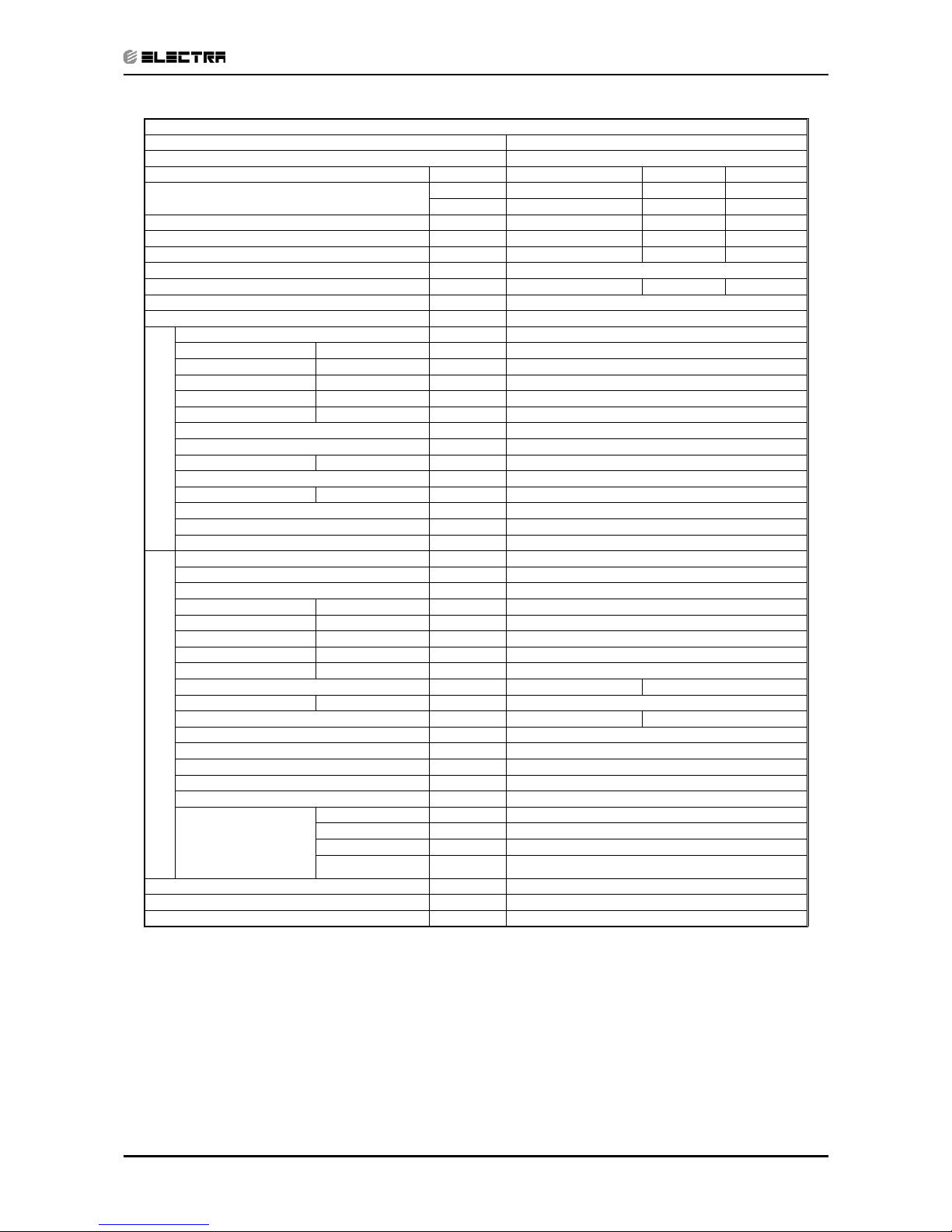
Model Indoor Unit WNG-7
Model Outdoor Unit GCN-7
Installation Method of Pipe Flared
Characteristics Units Cooling Only Cooling Heating
Capacity
(1)
Btu/hr 7710 7710 7610
kW 2.26 2.26 2.23
Power input
(1)
kW 0.8 0.8 0.690
EER (Cooling) or COP(Heating)
(1)
W/W 2.83 2.83 3.23
Energy efficiency class
C
CC
Power supply V/Ph/Hz 230V/Single/50Hz
Rated current A 3.5 3.5 3.0
Starting current A 22
Circuit breaker rating A 10
INDOOR
Fan type & quantity Crossflow x 1
Fan speeds H/M/L RPM 860/760/660
Air flow
(2)
H/M/L m3/hr 380/320/280
External static pressure Min-Max Pa 0
Sound power level
(3)
H/M/L dB(A) 45/41/39
Sound pressure level
(4)
H/M/L dB(A) 30/27/25
Moisture removal l/hr 0.8
Condenstate drain tube I.D mm 16
Dimensions WxHxD mm 810x285x190
Weight kg 11
Package dimensions WxHxD mm 885x285x360
Packaged weight kg 13.5
Units per pallet units 32
Stacking height units 8 levels
OUTDOOR
Refrigerant control Capillary tube
Compressor type,model Rotary,TOSHIBA PG135X1C-4DT3
Fan type & quantity Propeller(direct) x 1
Fan speeds H/L RPM 670
Air flow H/L m3/hr 1310
Sound power level H/L dB(A) 62
Sound pressure level
(4)
H/L dB(A) 51
Dimensions WxHxD mm 830*545*245
Weight kg 30 31
Package dimensions WxHxD mm 880*610*310
Packaged weight kg 31.5 32.5
Units per pallet Units 12
Stacking height units 3 levels
Refrigerant type R407C
Refrigerant chargless distance kg/m 0.72kg/4m
Additional charge per 1 meter g/m 4m<Lin<8m:+5g/m Lin>8m:+9g/m
Connections between
units
Liquid line In.(mm) Ф 1/4”(6.35)
Suction line In.(mm) Ф 3/8”(9.53)
Max.tubing length m. Max.15
Max.height
difference
m. Max.7
Operation control type Remote control
Heating elements kW 0.3
Others
(1)
Rating conditions in accordance with ISO 5151, ISO 13253 (for ducted units) and EN 14511.
(2)
Airflow in ducted units; at nominal external static pressure.
(3)
Sound power in ducted units is measured at air discharge.
(4)
Sound pressure level measured at 1 meter distance from unit.
Page 25
2-15
PRODUCT DATA SHEET
Revision Y05-03
Service Manual - WNG
Model Indoor Unit WNG-9
Model Outdoor Unit ONG3-9
Installation Method of Pipe Flared
Characteristics Units Cooling Only Cooling Heating
Capacity
(1)
Btu/hr 9280 9080 10200
kW 2.72 2.66 2.99
Power input
(1)
kW 0.9 0.88 0.920
EER (Cooling) or COP(Heating)
(1)
W/W 3.02 3.02 3.25
Energy efficiency class
B
BC
Power supply V/Ph/Hz 230V50HZ/Single
Rated current A 4 4.0 4.1
Starting current A 20
Circuit breaker rating A 10
INDOOR
Fan type & quantity Crossflow x 1
Fan speeds H/M/L RPM 960/860/760
Air flow
(2)
H/M/L m3/hr 450/380/330
External static pressure Min-Max Pa 0
Sound power level
(3)
H/M/L dB(A) 49/46/44
Sound pressure level
(4)
H/M/L dB(A) 35/31/28
Moisture removal l/hr 1
Condenstate drain tube I.D mm 16
Dimensions WxHxD mm 810x285x190
Weight kg 11
Package dimensions WxHxD mm 885x285x360
Packaged weight kg 13.5
Units per pallet units 32
Stacking height units 8 levels
OUTDOOR
Refrigerant control Capillary tube
Compressor type,model Rotary TOSHIBA PG170X1C-4FS3
Fan type & quantity Propeller(direct) x 1
Fan speeds H/L RPM 780
Air flow H/L m3/hr 1780
Sound power level H/L dB(A) 60
Sound pressure level
(4)
H/L dB(A) 50
Dimensions WxHxD mm 795x610x290
Weight kg 35 36
Package dimensions WxHxD mm 945x655x395
Packaged weight kg 38 39
Units per pallet Units 9
Stacking height units 3 levels
Refrigerant type R407C
Refrigerant chargless distance kg/m 0.88kg/4m
Additional charge per 1 meter g/m 4m<Lin<8m:+5g/m Lin>8m:+9g/m
Connections between
units
Liquid line In.(mm) Ф 1/4”(6.35)
Suction line In.(mm) Ф 3/8”(9.53)
Max.tubing length m. Max.15
Max.height
difference
m. Max.7
Operation control type Remote control
Heating elements kW 0.3
Others
(1)
Rating conditions in accordance with ISO 5151, ISO 13253 (for ducted units) and EN 14511.
(2)
Airflow in ducted units; at nominal external static pressure.
(3)
Sound power in ducted units is measured at air discharge.
(4)
Sound pressure level measured at 1 meter distance from unit.
Page 26
2-16
PRODUCT DATA SHEET
Revision Y05-03 Service Manual - WNG
Model Indoor Unit WNG-12
Model Outdoor Unit ONG3-12
Installation Method of Pipe Flared
Characteristics Units Cooling Only Cooling Heating
Capacity
(1)
Btu/hr
12390 12390 13000
kW 3.63 3.63 3.81
Power input
(1)
kW 1.2 1.2 1.180
EER (Cooling) or COP(Heating)
(1)
W/W 3.03 3.03 3.23
Energy efficiency class
B
BC
Power supply V/Ph/Hz 230V/Single/50Hz
Rated current A 5.3 5.3 5.3
Starting current A 30
Circuit breaker rating A 15
INDOOR
Fan type & quantity Crossflow x 1
Fan speeds H/M/L RPM 1230/1080/930
Air flow
(2)
H/M/L m3/hr 630/550/450
External static
pressure
Min-Max Pa 0
Sound power level
(3)
H/M/L dB(A) 56/53/50
Sound pressure
level
(4)
H/M/L dB(A) 44/39/34
Moisture removal l/hr 1.3
Condenstate drain tube I.D mm 16
Dimensions WxHxD mm 810x285x190
Weight kg 11
Package dimensions WxHxD mm 885x285x360
Packaged weight kg 13.5
Units per pallet units 32
Stacking height units 8 levels
OUTDOOR
Refrigerant control Capillary tube
Compressor type,model Rotary Toshiba PG215X2C-4FS
Fan type & quantity Propeller(direct) x 1
Fan speeds H/L RPM 810
Air flow H/L m3/hr 1850
Sound power level H/L dB(A) 62
Sound pressure
level
(4)
H/L dB(A) 52
Dimensions WxHxD mm 795x610x290
Weight kg 39 41
Package dimensions WxHxD mm 945x655x395
Packaged weight kg 42 45
Units per pallet Units 9
Stacking height units 3 levels
Refrigerant type R407C
Refrigerant chargless distance kg/m 0.97kg/4m
Additional charge per 1 meter g/m 4m<Lin<8m:+5g/m Lin>8m:+9g/m
Connections between
units
Liquid line In.(mm) Ф 1/4”(6.35)
Suction line In.(mm) Ф 1/2”(12.7)
Max.tubing length m. Max.15
Max.height
difference
m. Max.7
Operation control type Remote control
Heating elements kW 0.3
Others
(1)
Rating conditions in accordance with ISO 5151, ISO 13253 (for ducted units) and EN 14511.
(2)
Airflow in ducted units; at nominal external static pressure.
(3)
Sound power in ducted units is measured at air discharge.
(4)
Sound pressure level measured at 1 meter distance from unit.
Page 27
2-17
PRODUCT DATA SHEET
Revision Y05-03
Service Manual - WNG
Model Indoor Unit WNG-14
Model Outdoor Unit ONG3-14
Installation Method of Pipe Flared
Characteristics Units Cooling Only Cooling Heating
Capacity
(1)
Btu/hr 14190 14190 14880
kW 4.16 4.16 4.36
Power input
(1)
kW 1.46 1.46 1.540
EER (Cooling) or COP(Heating)
(1)
W/W 2.85 2.85 2.83
Energy efficiency class
C
CD
Power supply V/Ph/Hz 230V/Single/50Hz
Rated current A 6.5 6.5 6.9
Starting current A 33
Circuit breaker rating A 15
INDOOR
Fan type & quantity Crossflow x 1
Fan speeds H/M/L RPM 1280/1080/930
Air flow
(2)
H/M/L m3/hr 660/550/475
External static pressure Min-Max Pa 0
Sound power level
(3)
H/M/L dB(A) 59/53/48
Sound pressure level
(4)
H/M/L dB(A) 46/41/35
Moisture removal l/hr 1.7
Condenstate drain tube I.D mm 16
Dimensions WxHxD mm 810x285x190
Weight kg 11
Package dimensions WxHxD mm 885x285x360
Packaged weight kg 14
Units per pallet units 32
Stacking height units 8 levels
OUTDOOR
Refrigerant control Capillary tube
Compressor type,model Rotary TOSHIBA PG260X2C-4FT3
Fan type & quantity Propeller(direct) x 1
Fan speeds H/L RPM 920
Air flow H/L m3/hr 2160
Sound power level H/L dB(A) 64
Sound pressure level
(4)
H/L dB(A) 54
Dimensions WxHxD mm 795x610x290
Weight kg 41 42
Package dimensions WxHxD mm 945x655x395
Packaged weight kg 44 45
Units per pallet Units 9
Stacking height units 3 levels
Refrigerant type R407C
Refrigerant chargless distance kg/m 0.99kg/4m 1.09kg/4m
Additional charge per 1 meter g/m 4m<Lin<8m:+5g/m Lin>8m:+15g/m
Connections between
units
Liquid line In.(mm) Ф 1/4”(6.35)
Suction line In.(mm) Ф 1/2”(12.7)
Max.tubing length m. Max.15
Max.height
difference
m. Max.7
Operation control type Remote control
Heating elements kW 0.3
Others
(1)
Rating conditions in accordance with ISO 5151, ISO 13253 (for ducted units) and EN 14511.
(2)
Airflow in ducted units; at nominal external static pressure.
(3)
Sound power in ducted units is measured at air discharge.
(4)
Sound pressure level measured at 1 meter distance from unit.
Page 28
2-18
PRODUCT DATA SHEET
Revision Y05-03 Service Manual - WNG
Model Indoor Unit WNG- 30
Model Outdoor Unit OU833
Installation Method of Pipe Flared
Characteristics Units Cooling Only Cooling Heating
Capacity
(1)
Btu/hr 30000 30000 32910
kW 8.8 8.8 9.64
Power input
(1)
kW 3.38 3.38 3.88
EER (Cooling) or COP(Heating)
(1)
W/W 2.6 2.6 2.5
Energy efficiency class D D F
Power supply V/Ph/Hz 220-240V/Single/50Hz
Rated current A 14.4 14.4 16.1
Starting current A 76
Circuit breaker rating A 25
INDOOR
Fan type & quantity Cross flow x 1
Fan speeds H/M/L RPM 1300/1200/1000
Air flow
(2)
H/M/L m3/hr 1250/1040/830
External static pressure Min-Max Pa N/A
Sound power level
(3)
H/M/L dB(A) 64/59/53
Sound pressure
level(4)
H/M/L dB(A) 54/52/41
Moisture removal l/hr 3.2
Condensate drain tube I.D mm 16
Dimensions WxHxD mm 1200X340X236
Weight kg 18.5
Package dimensions WxHxD mm 1305X430X325
Packaged weight kg 25.5
Units per pallet units 12
Stacking height units 6 levels
OUTDOOR
Refrigerant control Capillary
Compressor type, model SCROLL HQ040PA
Fan type & quantity Propeller(direct) x 1
Fan speeds H/L RPM 850
Air flow H/L m3/hr 3110
Sound power level H/L dB(A) 69
Sound pressure level
(4)
H/L dB(A) 62
Dimensions WxHxD mm 900X860X340
Weight kg 78
Package dimensions WxHxD mm 903X907X435
Packaged weight kg 82
Units per pallet Units 6
Stacking height units 3 levels
Refrigerant type R407C
Refrigerant charge Kg/m 2.35/ 7.5m
Additional charge gr/m 25
Connections between
units
Liquid line In.(mm) 3/8”(9.53)
Suction line In.(mm) 3/4”(19.05)
Max.tubing
length
m. 30
Max.height
difference
m. 15
Operation control type Remote control
Heating elements kW
(1)
Rating conditions in accordance with ISO 5151, ISO 13253 (for ducted units) and EN 14511.
(2)
Airflow in ducted units; at nominal external static pressure.
(3)
Sound power in ducted units is measured at air discharge.
(4)
Sound pressure level measured at 1 meter distance from unit.
Page 29
2-19
PRODUCT DATA SHEET
Revision Y05-03
Service Manual - WNG
Model Indoor Unit WNG-30
Model Outdoor Unit OU830T
Installation Method of Pipe Flared
Characteristics Units Cooling Only Cooling Heating
Capacity
(1)
Btu/hr 29810 29810 31270
kW 8.73 8.73 9.16
Power input
(1)
kW 3.4 3.4 3.33
EER (Cooling) or COP(Heating)
(1)
W/W 2.56 2.56 2.75
Energy efficiency class E E E
Power supply V/Ph/Hz 400V/3PH/50Hz
Rated current A 6.5 6.5 6.7
Starting current A 35
Circuit breaker rating A 16
INDOOR
Fan type & quantity Cross flow x 1
Fan speeds H/M/L RPM 1300/1200/1000
Air flow
(2)
H/M/L m3/hr 1250/1040/830
External static pressure Min-Max Pa N/A
Sound power level
(3)
H/M/L dB(A) 64/59/53
Sound pressure level
(3)
H/M/L dB(A) 54/52/41
Moist4re removal l/hr 3.2
Condensate drain tube I.D mm 16
Dimensions WxHxD mm 1200X340X236
Weight kg 18.5
Package dimensions WxHxD mm 1305X430X325
Packaged weight kg 25.5
Units per pallet units 12
Stacking height units 6 levels
OUTDOOR
Refrigerant control Capillary + Nozzle Ass’y
Compressor type, model SCROLL HQ040YA
Fan type & quantity Propeller(direct) x 1
Fan speeds H/L RPM 850
Air flow H/L m3/hr 3110
Sound power level H/L dB(A) 69
Sound pressure level
(4)
H/L dB(A) 62
Dimensions WxHxD mm 900X860X340
Weight kg 78
Package dimensions WxHxD mm 903X907X435
Packaged weight kg 82
Units per pallet Units 6
Stacking height units 3 levels
Refrigerant type R407C
Refrigerant charge kg/m 2.36/7.5m
Additional charge gr/m 25
Connections between
units
Liquid line In.(mm) 3/8”(9.53)
Suction line In.(mm) 3/4”(19.05)
Max.tubing
length
m. 30
Max.height
difference
m. 15
Operation control type Remote control
(1)
Rating conditions in accordance with ISO 5151, ISO 13253 (for ducted units) and EN 14511.
(2)
Airflow in ducted units; at nominal external static pressure.
(3)
Sound power in ducted units is measured at air discharge.
(4)
Sound pressure level measured at 1 meter distance from unit.
Page 30

2-20
PRODUCT DATA SHEET
Revision Y05-03 Service Manual - WNG
2.3 R22
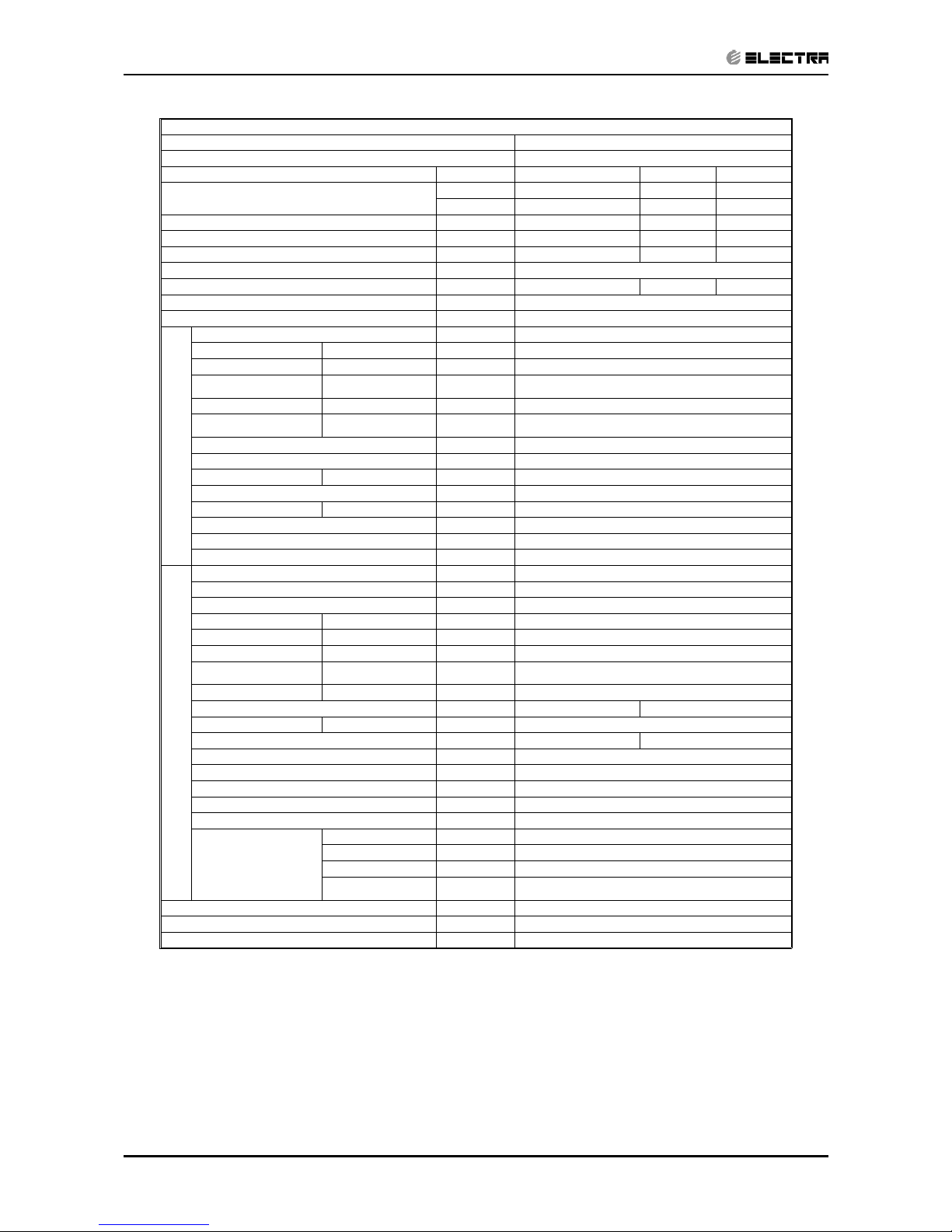
Model Indoor Unit WNG-7
Model Outdoor Unit GCN-7
Installation Method of Pipe Flared
Characteristics Units cooling only Cooling Heating
Capacity
(1)
Btu/hr 7710 7710 7610
kW 2.27 2.27 2.32
Power input
(1)
kW 0.8 0.8 0.680
EER (Cooling) or COP(Heating)
(1)
W/W 2.84 2.84 3.41
Energy efficiency class
C
CB
Power supply V/Ph/Hz 230V/50Hz/Single
Rated current A 3.6 3.6 3.1
Starting current A 16
Circuit breaker rating A 10
INDOOR
Fan type & quantity Crossflow x 1
Fan speeds H/M/L RPM 860/760/660
Air flow
(2)
H/M/L m3/hr 380/320/280
External static pressure Min-Max Pa 0
Sound power level
(3)
H/M/L dB(A) 45/41/39
Sound pressure level
(4)
H/M/L dB(A) 30/27/25
Moisture removal l/hr 0.8
Condenstate drain tube I.D mm 16
Dimensions WxHxD mm 810x285x190
Weight kg 11
Package dimensions WxHxD mm 885x285x360
Packaged weight kg 13.5
Units per pallet units 32
Stacking height units 8 levels
OUTDOOR
Refrigerant control Capillary tube
Compressor type,model Rotary,SD134CV-H6AUA
Fan type & quantity Propeller(direct) x 1
Fan speeds H/L RPM 670
Air flow H/L m3/hr 1400
Sound power level H/L dB(A) 59
Sound pressure level
(4)
H/L dB(A) 49
Dimensions WxHxD mm 830*245*545
Weight kg 30 31
Package dimensions WxHxD mm 880*310*610
Packaged weight kg 31.5 32.5
Units per pallet Units 12
Stacking height units 3 levels
Refrigerant type R22
Refrigerant chargless distance kg/m 0.7kg/4m
Additional charge per 1 meter g/m 4m<Lin<8m:+5g/m Lin>8m:+9g/m
Connections between
units
Liquid line In.(mm) 1/4”(6.35)
Suction line In.(mm) 3/8”(9.53)
Max.tubing length m. Max.15
Max.height
difference
m. Max.7
Operation control type Remote control
Heating elements kW 0.3
Others
(1)
Rating conditions in accordance with ISO 5151, ISO 13253 (for ducted units) and EN 14511.
(2)
Airflow in ducted units; at nominal external static pressure.
(3)
Sound power in ducted units is measured at air discharge.
(4)
Sound pressure level measured at 1 meter distance from unit.
Page 31

2-21
PRODUCT DATA SHEET
Revision Y05-03
Service Manual - WNG
Model Indoor Unit WNG-9
Model Outdoor Unit GCN-9
Installation Method of Pipe Flared
Characteristics Units cooling only Cooling Heating
Capacity
(1)
Btu/hr 9550 9080 10200
kW 2.8 2.80 2.83
Power input
(1)
kW 0.99 0.99 0.920
EER (Cooling) or COP(Heating)
(1)
W/W 2.83 2.83 3.08
Energy efficiency class
C
CD
Power supply V/Ph/Hz 230V50HZ/Single
Rated current A 4.5 4.5 4.2
Starting current A 26
Circuit breaker rating A 10
INDOOR
Fan type & quantity Crossflow x 1
Fan speeds H/M/L RPM 960/860/760
Air flow
(2)
H/M/L m3/hr 450/380/330
External static pressure Min-Max Pa 0
Sound power level
(3)
H/M/L dB(A) 49/46/44
Sound pressure level
(4)
H/M/L dB(A) 35/31/28
Moisture removal l/hr 1.2
Condenstate drain tube I.D mm 16
Dimensions WxHxD mm 810x285x190
Weight kg 11
Package dimensions WxHxD mm 885x285x360
Packaged weight kg 13.5
Units per pallet units 32
Stacking height units 8 levels
OUTDOOR
Refrigerant control Capillary tube
Compressor type,model Rotary PH170X1C-4FS2
Fan type & quantity Propeller(direct) x 1
Fan speeds H/L RPM 750
Air flow H/L m3/hr 1550
Sound power level H/L dB(A) 59
Sound pressure level
(4)
H/L dB(A) 49
Dimensions WxHxD mm 830*245*545
Weight kg 31 32
Package dimensions WxHxD mm 880*310*610
Packaged weight kg 35 36
Units per pallet Units 12
Stacking height units 3 levels
Refrigerant type R22
Refrigerant chargless distance kg/m 0.8kg/4m
Additional charge per 1 meter g/m 4m<Lin<8m:+5g/m Lin>8m:+9g/m
Connections between
units
Liquid line In.(mm) 1/4”(6.35)
Suction line In.(mm) 3/8”(9.53)
Max.tubing length m. Max.15
Max.height
difference
m. Max.7
Operation control type Remote control
Heating elements kW 0.3
Others
(1)
Rating conditions in accordance with ISO 5151, ISO 13253 (for ducted units) and EN 14511.
(2)
Airflow in ducted units; at nominal external static pressure.
(3)
Sound power in ducted units is measured at air discharge.
(4)
Sound pressure level measured at 1 meter distance from unit.
Page 32

2-22
PRODUCT DATA SHEET
Revision Y05-03 Service Manual - WNG
Model Indoor Unit WNG-9
Model Outdoor Unit ONG3-9
Installation Method of Pipe Flared
Characteristics Units cooling only Cooling Heating
Capacity
(1)
Btu/hr 9690 9080 10200
kW 2.84 2.84 2.90
Power input
(1)
kW 0.93 0.93 0.900
EER (Cooling) or COP(Heating)
(1)
W/W 3.05 3.05 3.22
Energy efficiency class
B
BC
Power supply V/Ph/Hz 230V50HZ/Single
Rated current A 4.2 4.2 4.0
Starting current A 25
Circuit breaker rating A 10
INDOOR
Fan type & quantity Crossflow x 1
Fan speeds H/M/L RPM 960/860/760
Air flow
(2)
H/M/L m3/hr 450/380/330
External static pressure Min-Max Pa 0
Sound power level
(3)
H/M/L dB(A) 49/46/44
Sound pressure level
(4)
H/M/L dB(A) 35/31/28
Moisture removal l/hr 1
Condenstate drain tube I.D mm 16
Dimensions WxHxD mm 810x285x190
Weight kg 11
Package dimensions WxHxD mm 885x285x360
Packaged weight kg 13.5
Units per pallet units 32
Stacking height units 8 levels
OUTDOOR
Refrigerant control Capillary tube
Compressor type,model Rotary PH170X1C-4FS2
Fan type & quantity Propeller(direct) x 1
Fan speeds H/L RPM 730
Air flow H/L m3/hr 1770
Sound power level H/L dB(A) 58
Sound pressure level
(4)
H/L dB(A) 48
Dimensions WxHxD mm 795x290x610
Weight kg 34
Package dimensions WxHxD mm 945x395x655
Packaged weight kg 37
Units per pallet Units 9
Stacking height units 3 levels
Refrigerant type R407C
Refrigerant chargless distance kg/m 0.79kg/4m
Additional charge per 1 meter g/m 4m<Lin<8m:+5g/m Lin>8m:+9g/m
Connections between
units
Liquid line In.(mm) 1/4”(6.35)
Suction line In.(mm) 3/8”(9.53)
Max.tubing length m. Max.15
Max.height
difference
m. Max.7
Operation control type Remote control
Heating elements kW 0.3
Others
(1)
Rating conditions in accordance with ISO 5151, ISO 13253 (for ducted units) and EN 14511.
(2)
Airflow in ducted units; at nominal external static pressure.
(3)
Sound power in ducted units is measured at air discharge.
(4)
Sound pressure level measured at 1 meter distance from unit.
Page 33

2-23
PRODUCT DATA SHEET
Revision Y05-03
Service Manual - WNG
Model Indoor Unit WNG-12
Model Outdoor Unit GCN-12
Installation Method of Pipe Flared
Characteristics Units cooling only Cooling Heating
Capacity
(1)
Btu/hr 12280 12280 13000
kW 3.6 3.6 3.72
Power input
(1)
kW 1.25 1.25 1.27
EER (Cooling) or COP(Heating)
(1)
W/W 2.88 2.88 2.93
Energy efficiency class
C
CD
Power supply V/Ph/Hz 230V/50Hz/Single
Rated current A 5.4 5.4 5.5
Starting current A 33
Circuit breaker rating A 15
INDOOR
Fan type & quantity Crossflow x 1
Fan speeds H/M/L RPM 1080/960/840
Air flow
(2)
H/M/L m3/hr 525/450/370
External static pressure Min-Max Pa 0
Sound power level
(3)
H/M/L dB(A) 51/48/44
Sound pressure level
(4)
H/M/L dB(A) 39/36/32
Moisture removal l/hr 1.8
Condenstate drain tube I.D mm 16
Dimensions WxHxD mm 810x285x190
Weight kg 11
Package dimensions WxHxD mm 885x285x360
Packaged weight kg 14
Units per pallet units 32
Stacking height units 8 levels
OUTDOOR
Refrigerant control Capillary tube
Compressor type,model Rotary Toshiba PH225X2C-4FS
Fan type & quantity Propeller(direct) x 1
Fan speeds H/L RPM 830
Air flow H/L m3/hr 1550
Sound power level H/L dB(A) 62
Sound pressure level
(4)
H/L dB(A) 52
Dimensions WxHxD mm 830*245*545
Weight kg 36 37
Package dimensions WxHxD mm 880*310*610
Packaged weight kg 39 40
Units per pallet Units 12
Stacking height units 3 levels
Refrigerant type R22
Refrigerant chargless distance kg/m 1.14kg/4m
Additional charge per 1 meter g/m 4m<Lin<8m:+5g/m Lin>8m:+9g/m
Connections between
units
Liquid line In.(mm) 1/4”(6.35)
Suction line In.(mm) 1/2”(12.7)
Max.tubing length m. Max.15
Max.height
difference
m. Max.7
Operation control type Remote control
Heating elements kW 0.3
Others
(1)
Rating conditions in accordance with ISO 5151, ISO 13253 (for ducted units) and EN 14511.
(2)
Airflow in ducted units; at nominal external static pressure.
(3)
Sound power in ducted units is measured at air discharge.
(4)
Sound pressure level measured at 1 meter distance from unit.
Page 34

2-24
PRODUCT DATA SHEET
Revision Y05-03 Service Manual - WNG
Model Indoor Unit WNG-12
Model Outdoor Unit ONG3-12
Installation Method of Pipe Flared
Characteristics Units cooling only Cooling Heating
Capacity
(1)
Btu/hr 12280 12280 13000
kW 3.6 3.60 3.72
Power input
(1)
kW 1.23 1.23 1.230
EER (Cooling) or COP(Heating)
(1)
W/W 2.93 2.93 3.02
Energy efficiency class
C
CD
Power supply V/Ph/Hz 230V/50Hz/Single
Rated current A 5.4 5.4 5.4
Starting current A 32
Circuit breaker rating A 15
INDOOR
Fan type & quantity Crossflow x 1
Fan speeds H/M/L RPM 1080/960/840
Air flow
(2)
H/M/L m3/hr 525/450/370
External static pressure Min-Max Pa 0
Sound power level
(3)
H/M/L dB(A) 51/48/44
Sound pressure level
(4)
H/M/L dB(A) 39/36/32
Moisture removal l/hr 1.8
Condenstate drain tube I.D mm 16
Dimensions WxHxD mm 810x285x190
Weight kg 11
Package dimensions WxHxD mm 885x285x360
Packaged weight kg 14
Units per pallet units 32
Stacking height units 8 levels
OUTDOOR
Refrigerant control Capillary tube
Compressor type,model Rotary PH225X2C-4FS
Fan type & quantity Propeller(direct) x 1
Fan speeds H/L RPM 780
Air flow H/L m3/hr 1840
Sound power level H/L dB(A) 60
Sound pressure level
(4)
H/L dB(A) 50
Dimensions WxHxD mm 795x610x290
Weight kg 38
Package dimensions WxHxD mm 945x655x395
Packaged weight kg 45
Units per pallet Units 9
Stacking height units 3 levels
Refrigerant type R22
Refrigerant chargless distance kg/m 0.97kg/4m
Additional charge per 1 meter g/m 4m<Lin<8m:+5g/m Lin>8m:+9g/m
Connections between
units
Liquid line In.(mm) 1/4”(6.35)
Suction line In.(mm) 1/2”(12.7)
Max.tubing length m. Max.15
Max.height
difference
m. Max.7
Operation control type Remote control
Heating elements kW 0.3
Others
(1)
Rating conditions in accordance with ISO 5151, ISO 13253 (for ducted units) and EN 14511.
(2)
Airflow in ducted units; at nominal external static pressure.
(3)
Sound power in ducted units is measured at air discharge.
(4)
Sound pressure level measured at 1 meter distance from unit.
Page 35

2-25
PRODUCT DATA SHEET
Revision Y05-03
Service Manual - WNG
Model Indoor Unit WNG-14
Model Outdoor Unit GC-14
Installation Method of Pipe Flared
Characteristics Units cooling only Cooling Heating
Capacity
(1)
Btu/hr 14190 14190 14880
kW 4.12 4.12 4.75
Power input
(1)
kW 1.65 1.65 1.690
EER (Cooling) or COP(Heating)
(1)
W/W 2.50 2.50 2.81
Energy efficiency class
E
ED
Power supply V/Ph/Hz 230V/50Hz/Single
Rated current A 7.5 7.5 7.7
Starting current A 41
Circuit breaker rating A 15
INDOOR
Fan type & quantity Crossflow x 1
Fan speeds H/M/L RPM 1230/1080/930
Air flow
(2)
H/M/L m3/hr 635/550/450
External static pressure Min-Max Pa 0
Sound power level
(3)
H/M/L dB(A) 55/51/47
Sound pressure level
(4)
H/M/L dB(A) 43/39/35
Moisture removal l/hr 2
Condenstate drain tube I.D mm 16
Dimensions WxHxD mm 810x285x190
Weight kg 11
Package dimensions WxHxD mm 885x285x360
Packaged weight kg 14.5
Units per pallet units 32
Stacking height units 8 levels
OUTDOOR
Refrigerant control Capillary tube
Compressor type,model Rotary QJ292PT23A
Fan type & quantity Propeller(direct) x 1
Fan speeds H/L RPM 830
Air flow H/L m3/hr 1720
Sound power level H/L dB(A) 64
Sound pressure level
(4)
H/L dB(A) 54
Dimensions WxHxD mm 830*245*545
Weight kg 37 38
Package dimensions WxHxD mm 880*310*610
Packaged weight kg 41 42
Units per pallet Units 12
Stacking height units 3 levels
Refrigerant type R22
Refrigerant chargless distance kg/m 1.0kg/4m
Additional charge per 1 meter g/m 4m<Lin<8m:+5g/m Lin>8m:+9g/m
Connections between
units
Liquid line In.(mm) 1/4”(6.35)
Suction line In.(mm) 1/2”(12.7)
Max.tubing length m. Max.15
Max.height
difference
m. Max.7
Operation control type Remote control
Heating elements kW 0.3
Others
(1)
Rating conditions in accordance with ISO 5151, ISO 13253 (for ducted units) and EN 14511.
(2)
Airflow in ducted units; at nominal external static pressure.
(3)
Sound power in ducted units is measured at air discharge.
(4)
Sound pressure level measured at 1 meter distance from unit.
Page 36

2-26
PRODUCT DATA SHEET
Revision Y05-03 Service Manual - WNG
Model Indoor Unit WNG-14
Model Outdoor Unit ONG3-14
Installation Method of Pipe Flared
Characteristics Units cooling only Cooling Heating
Capacity
(1)
Btu/hr 14190 14190 14880
kW 4.2 4.2 4.7
Power input
(1)
kW 1.55 1.55 1.67
EER (Cooling) or COP(Heating)
(1)
W/W 2.71 2.71 2.81
Energy efficiency class
D
DD
Power supply V/Ph/Hz 230V/50Hz/Single
Rated current A 6.9 6.9 7.5
Starting current A 41
Circuit breaker rating A 15
INDOOR
Fan type & quantity Crossflow x 1
Fan speeds H/M/L RPM 1230/1080/930
Air flow
(2)
H/M/L m3/hr 635/550/450
External static pressure Min-Max Pa 0
Sound power level
(3)
H/M/L dB(A) 55/51/47
Sound pressure level
(4)
H/M/L dB(A) 43/39/35
Moisture removal l/hr 2
Condenstate drain tube I.D mm 16
Dimensions WxHxD mm 810x285x190
Weight kg 11
Package dimensions WxHxD mm 885x285x360
Packaged weight kg 14.5
Units per pallet units 32
Stacking height units 8 levels
OUTDOOR
Refrigerant control Capillary tube
Compressor type,model Rotary QJ292PT23A
Fan type & quantity Propeller(direct) x 1
Fan speeds H/L RPM 810
Air flow H/L m3/hr 1850
Sound power level H/L dB(A) 62
Sound pressure level
(4)
H/L dB(A) 52
Dimensions WxHxD mm 795x610x290
Weight kg 41
Package dimensions WxHxD mm 945x655x395
Packaged weight kg 45
Units per pallet Units 9
Stacking height units 3 levels
Refrigerant type R22
Refrigerant chargless distance kg/m 1.08kg/4m
Additional charge per 1 meter g/m 4m<Lin<8m:+9g/m Lin>8m:+15g/m
Connections between
units
Liquid line In.(mm) 1/4”(6.35)
Suction line In.(mm) 1/2”(12.7)
Max.tubing length m. Max.15
Max.height
difference
m. Max.7
Operation control type Remote control
Heating elements kW 0.3
Others
(1)
Rating conditions in accordance with ISO 5151, ISO 13253 (for ducted units) and EN 14511.
(2)
Airflow in ducted units; at nominal external static pressure.
(3)
Sound power in ducted units is measured at air discharge.
(4)
Sound pressure level measured at 1 meter distance from unit.
Page 37

2-27
PRODUCT DATA SHEET
Revision Y05-03
Service Manual - WNG
Model Indoor Unit WNG-25
Model Outdoor Unit GC-24
Installation Method of Pipe Flared
Characteristics Units cooling only Cooling Heating
Capacity
(1)
Btu/hr 24050 24050 24230
kW 7.05 7.05 7.1
Power input
(1)
kW 2.51 2.51 2.35
EER (Cooling) or COP(Heating)
(1)
W/W 2.81 2.81 3.02
Energy efficiency class A A B
Power supply V/Ph/Hz 230V/Single/50Hz
Rated current A 11.4 11.4 10.8
Starting current A 58
Circuit breaker rating A 20
INDOOR
Fan type & quantity Crossflow x 1
Fan speeds H/M/L RPM 1050/930/800
Air flow
(2)
H/M/L m3/hr 1050/930/800
External static
pressure
Min-Max Pa 0
Sound power level
(3)
H/M/L dB(A) 59/55/52
Sound pressure
level
(4)
H/M/L dB(A) 46/43/39
Moisture removal l/hr 3.5
Condenstate drain tube I.D mm 16
Dimensions WxHxD mm 1200X340X236
Weight kg 17
Package dimensions WxHxD mm 1305X430X325
Packaged weight kg 25.5
Units per pallet units 12
Stacking height units 6 levels
OUTDOOR
Refrigerant control Capillary tube restrictor for heating)
Compressor type,model Scroll,LG SQ032PBA
Fan type & quantity Propeller(direct) x 1
Fan speeds H/L RPM 850
Air flow H/L m3/hr 2480
Sound power level H/L dB(A) 70
Sound pressure
level
(4)
H/L dB(A) 60
Dimensions WxHxD mm 846X302X690
Weight kg 58
Package dimensions WxHxD mm 990X430X770
Packaged weight kg 61
Units per pallet Units 9
Stacking height units 3 levels
Refrigerant type R22
Refrigerant chargless distance kg/m 1.66kg/7.5m
Additional charge g/m 7.5m<Lin<25m:+25g/m 7.5m<Lin<25m:+60g/m
Connections between
units
Liquid line In.(mm) 3/8”(9.53)
Suction line In.(mm) 5/8”(15.88)
Max.tubing length m. Max.25
Max.height
difference
m. Max.10
Operation control type Remote control
Heating elements kW 0.3
Others
(1)
Rating conditions in accordance with ISO 5151, ISO 13253 (for ducted units) and EN 14511.
(2)
Airflow in ducted units; at nominal external static pressure.
(3)
Sound power in ducted units is measured at air discharge.
(4)
Sound pressure level measured at 1 meter distance from unit.
Page 38

2-28
PRODUCT DATA SHEET
Revision Y05-03 Service Manual - WNG
Model Indoor Unit WNG-30
Model Outdoor Unit GC-30
Installation Method of Pipe Flared
Characteristics Units cooling only Cooling Heating
Capacity
(1)
Btu/hr 29000 29000 32410
kW 8.5 8.5 9.5
Power input
(1)
kW 3.1 3.1 3.25
EER (Cooling) or COP(Heating)
(1)
W/W 2.74 2.74 2.92
Energy efficiency class A A B
Power supply V/Ph/Hz 230V/Single/50Hz
Rated current A 13.7 13.7 14.2
Starting current A 73
Circuit breaker rating A 25
INDOOR
Fan type & quantity Crossflow x 1
Fan speeds H/M/L RPM 1250/1050/850
Air flow
(2)
H/M/L m3/hr 1300/1050/900
External static pressure Min-Max Pa 0
Sound power level
(3)
H/M/L dB(A) 65/61/57
Sound pressure level
(4)
H/M/L dB(A) 52/48/44
Moisture removal l/hr 4
Condenstate drain tube I.D mm 16
Dimensions WxHxD mm 1200X340X236
Weight kg 18.5
Package dimensions WxHxD mm 1305X430X325
Packaged weight kg 24
Units per pallet units 12
Stacking height units 6 levels
OUTDOOR
Refrigerant control Capillary tube restrictor for heating)
Compressor type,model Scroll,LG SQ040PAA
Fan type & quantity Propeller(direct) x 1
Fan speeds H/L RPM 880
Air flow H/L m3/hr 3200
Sound power level H/L dB(A) 71
Sound pressure level
(4)
H/L dB(A) 61
Dimensions WxHxD mm 950*340*835
Weight kg 87 90
Package dimensions WxHxD mm 1080*477*910
Packaged weight kg 105
Units per pallet Units 9
Stacking height units 3 levels
Refrigerant type R22
Refrigerant chargless distance kg/m 2.39kg/7.5m
Additional charge g/m 7.5m<Lin<30m:+25g/m
Connections between
units
Liquid line In.(mm) 3/8”(9.53)
Suction line In.(mm) 5/8”(15.88)
Max.tubing length m. Max.30
Max.height
difference
m. Max.20
Operation control type Remote control
Heating elements kW 0.3
Others
(1)
Rating conditions in accordance with ISO 5151, ISO 13253 (for ducted units) and EN 14511.
(2)
Airflow in ducted units; at nominal external static pressure.
(3)
Sound power in ducted units is measured at air discharge.
(4)
Sound pressure level measured at 1 meter distance from unit.
Page 39

2-29
PRODUCT DATA SHEET
Revision Y05-03
Service Manual - WNG
Model Indoor Unit WNG- 30
Model Outdoor Unit OU830
Installation Method of Pipe Flared
Characteristics Units Cooling Only Cooling Heating
Capacity
(1)
Btu/hr 30000 30000 29500
kW 8.8 8.8 8.65
Power input
(1)
kW 3.2 3.2 3.3
EER (Cooling) or COP(Heating)
(1)
W/W 2.75 2.75 2.65
Energy efficiency class D D E
Power supply V/Ph/Hz 220-240V/Single/50Hz
Rated current A 13.9 13.9 14.3
Starting current A 76
Circuit breaker rating A 16
INDOOR
Fan type & quantity Cross flow x 1
Fan speeds H/M/L RPM 1300/1200/1000
Air flow
(2)
H/M/L m3/hr 1250/1040/830
External static pressure Min-Max Pa N/A
Sound power level
(3)
H/M/L dB(A) 64/59/53
Sound pressure level
(4)
H/M/L dB(A) 54/52/41
Moisture removal l/hr 3.2
Condensate drain tube I.D mm 16
Dimensions WxHxD mm 1200X340X236
Weight kg 18.5
Package dimensions WxHxD mm 1305X430X325
Packaged weight kg 25.5
Units per pallet units 12
Stacking height units 6 levels
OUTDOOR
Refrigerant control Capillary
Compressor type, model SCROLL SQ040PA
Fan type & quantity Propeller(direct) x 1
Fan speeds H/L RPM 850
Air flow H/L m3/hr 3110
Sound power level H/L dB(A) 69
Sound pressure level
(4)
H/L dB(A) 62
Dimensions WxHxD mm 900X860X340
Weight kg 78
Package dimensions WxHxD mm 903X907X435
Packaged weight kg 82
Units per pallet Units 6
Stacking height units 3 levels
Refrigerant type R22
Refrigerant charge less distance kg/m 2 / 7.5M
Additional charge gr/m 30
Connections between
units
Liquid line In.(mm) 3/8”(9.53)
Suction line In.(mm) 3/4”(19.05)
Max.tubing
length
m. 30
Max.height
difference
m. 15
Operation control type Remote control
(1)
Rating conditions in accordance with ISO 5151, ISO 13253 (for ducted units) and EN 14511.
(2)
Airflow in ducted units; at nominal external static pressure.
(3)
Sound power in ducted units is measured at air discharge.
(4)
Sound pressure level measured at 1 meter distance from unit.
Page 40

2-30
PRODUCT DATA SHEET
Revision Y05-03 Service Manual - WNG
Model Indoor Unit WNG-30
Model Outdoor Unit OU830T
Installation Method of Pipe Flared
Characteristics Units Cooling Only Cooling Heating
Capacity
(1)
Btu/hr 30000 30000 30000
kW 8.8 8.8 8.8
Power input
(1)
kW 3 3 3
EER (Cooling) or COP(Heating)
(1)
W/W 2.9 2.9 2.9
Energy efficiency class C C D
Power supply V/Ph/Hz 400V/3PH/50Hz
Rated current A 6.5 6.5 6.7
Starting current A 35
Circuit breaker rating A 16
INDOOR
Fan type & quantity Cross flow x 1
Fan speeds H/M/L RPM 1300/1200/1000
Air flow
(2)
H/M/L m3/hr 1250/1040/830
External static pressure Min-Max Pa N/A
Sound power level
(3)
H/M/L dB(A) 64/59/53
Sound pressure level
(4)
H/M/L dB(A) 54/52/41
Moisture removal l/hr 3.2
Condensate drain tube I.D mm 16
Dimensions WxHxD mm 1200X340X236
Weight kg 18.5
Package dimensions WxHxD mm 1305X430X325
Packaged weight kg 25.5
Units per pallet units 12
Stacking height units 6 levels
OUTDOOR
Refrigerant control Capillary
Compressor type, model SCROLL SQ040YA
Fan type & quantity Propeller(direct) x 1
Fan speeds H/L RPM 850
Air flow H/L m3/hr 3110
Sound power level H/L dB(A) 69
Sound pressure level
(4)
H/L dB(A) 62
Dimensions WxHxD mm 900X860X340
Weight kg 78
Package dimensions WxHxD mm 903X907X435
Packaged weight kg 82
Units per pallet Units 6
Stacking height units 3 levels
Refrigerant type R22
Refrigerant charge less distance kg/m 2 / 7.5M
Additional charge gr/m 30
Connections between
units
Liquid line In.(mm) 3/8”(9.53)
Suction line In.(mm) 3/4”(19.05)
Max.tubing
length
m. 30
Max.height
difference
m. 15
Operation control type Remote control
(1)
Rating conditions in accordance with ISO 5151, ISO 13253 (for ducted units) and EN 14511.
(2)
Airflow in ducted units; at nominal external static pressure.
(3)
Sound power in ducted units is measured at air discharge.
(4)
Sound pressure level measured at 1 meter distance from unit.
Page 41

3-1
RATING CONDITIONS
Revision Y05-03
Service Manual - WNG
3. RATING CONDITIONS
Standard conditions in accordance with ISO 5151, ISO 13253 (for ducted units)
and EN 14511.
Cooling:
Indoor: 27oC DB 19oC WB
Outdoor: 35 oC DB
Heating:
Indoor: 20oC DB
Outdoor: 7oC DB 6oC WB
3.1 Operating Limits
3.1.1 R410A
Indoor Outdoor
Cooling
Upper limit 32
o
C DB 23oC WB 46oC DB
Lower limit 21
o
C DB 15oC WB 10oC DB
Heating
Upper limit 27
o
C DB 24oC DB 18oC WB
Lower limit 10
o
C DB -9oC DB -10oC WB
Voltage
1PH 198 – 264 V
3PH 360 – 440 V
3.1.2 R407C
Indoor Outdoor
Cooling
Upper limit 32
o
C DB 23oC WB 46oC DB
Lower limit 21
o
C DB 15oC WB 10oC DB
Heating
Upper limit 27
o
C DB 24oC DB 18oC WB
Lower limit 10
o
C DB -9oC DB -10oC WB
Voltage
1PH 198 – 264 V
3PH 360 – 440 V
3.1.3 R22
Indoor Outdoor
Cooling
Upper limit 32
o
C DB 23oC WB 46oC DB
Lower limit 21
o
C DB 15oC WB 10oC DB
Heating
Upper limit 27
o
C DB 24oC DB 18oC WB
Lower limit 10
o
C DB -5oC DB -6oC WB
Voltage
1PH 198 – 264 V
3PH 360 – 440 V
Page 42

4-1
OUTLINE DIMENSIONS
Revision Y05-03
Service Manual - WNG
4. OUTLINE DIMENSIONS
4.1 WNG 7, 9, 12, 14
4.2
WNG 18, 21, 24
Page 43

4-2
OUTLINE DIMENSIONS
Revision Y05-03 Service Manual - WNG
4.3 WNG 25, 30, 36
4.4 ONG 7, 9, 12, 14 RC/ST
150mm
Page 44

4-3
OUTLINE DIMENSIONS
Revision Y05-03
Service Manual - WNG
4.5 GCN 7, 9, 12, 14 RC/ST
4.6 GC 18, 21, 24 RC/ST
AI R OUTL E T
AI R I NTAKE
Page 45

4-4
OUTLINE DIMENSIONS
Revision Y05-03 Service Manual - WNG
4.7 GC 30 RC/ST
4.8 OU7-24 RC/ST
Page 46

4-5
OUTLINE DIMENSIONS
Revision Y05-03
Service Manual - WNG
4.9 OU8-33 RC/ST
4.10 OU10-36 RC/ST
Page 47

5-1
PERFORMANCE DATA & PRESSURE CURVES
Revision Y05-03
Service Manual - WNG
5. PERFORMANCE DATA & PRESSURE CURVES
5.1 WNG7 ONG7 R410A
5.1.1 Cooling Mode at 7.5m Tubing Connection.
230V : Indoor Fan at High Speed.
ENTERING AIR
DB OU COIL (°C)
DATA
ENTERING AIR WB/DB ID COIL ( °C)
15/21 17/24 19/27 21/29 23/32
15
(1)
TC
2.35 2.43 2.49 2.55 2.59
SC
1.66 1.74 1.80 1.85 1.88
PI
0.48 0.48 0.48 0.49 0.49
20
(1)
TC
2.27 2.40 2.47 2.53 2.59
SC
1.63 1.72 1.79 1.84 1.88
PI
0.52 0.53 0.53 0.53 0.53
25
TC
2.15 2.32 2.44 2.52 2.58
SC
1.59 1.69 1.78 1.83 1.86
PI
0.57 0.57 0.57 0.58 0.58
30
TC
2.01 2.19 2.37 2.45 2.52
SC
1.54 1.64 1.74 1.79 1.83
PI
0.61 0.62
0.62
0.63 0.64
35
TC
1.86 2.02
2.23
2.34 2.45
SC
1.46 1.57 1.70 1.75 1.78
PI
0.66 0.67
0.68
0.69 0.69
40
TC
1.69 1.84
2.01
2.20 2.31
SC
1.38 1.49 1.61 1.66 1.69
PI
0.71 0.72 0.73 0.74 0.75
46
TC
1.47 1.61 1.77 1.95 2.10
SC
1.27 1.36 1.47 1.52 1.55
PI
0.78 0.79 0.81 0.82 0.83
LEGEND
TC – Total Cooling Capacity, kW
SC – Sensible Capacity, kW
PI – Power Input, kW
WB – Wet Bulb Temp., (
o
C)
DB – Dry Bulb Temp., (oC)
ID – Indoor
OU – Outdoor
(1) Marked area is below standard operating limits. For operating in low ambient
conditions, refer to Optional Accessories (Chapter 15).
Page 48

5-2
PERFORMANCE DATA & PRESSURE CURVES
Revision Y05-03 Service Manual - WNG
5.1.2 Heating Mode at 7.5m Tubing Connection.
230V : Indoor Fan at High Speed.
ENTERING AIR DB ID COIL ( °C)
15 20 25
ENTERING AIR
WB OU COIL ( °C)
TH PI TH PI TH PI
-10 1.20 0.54 1.15 0.57 1.11 0.60
-7 1.29 0.55 1.24 0.58 1.20 0.61
-2 1.37 0.56 1.32 0.59 1.28 0.62
2 1.66 0.58
1.60 0.62
1.53 0.66
6 2.35 0.63 2.28 0.67 2.20 0.71
10 2.55 0.66
2.49 0.71
2.42 0.76
15 2.76 0.69 2.69 0.74 2.62 0.79
20 2.91 0.71 2.84 0.77 2.76 0.83
* the above chart includes the weighted deicing infleuence.
LEGEND
TH – Total Heating Capacity, kW
PI – Power Input, kW
WB – Wet Bulb Temp., (
o
C)
DB – Dry Bulb Temp., (
o
C)
ID – Indoor
OU – Outdoor
5.2 Capacity Correction Factor Due to Tubing Length
5.2.1 Cooling
TOTAL TUBING LENGTH (One Way)
3m
7.5m
10m 15m 20m 25m 30m 40m 50m
1.02
1
0.961 0.949 --- --- --- --- ---
* Minimum recommended tubing length between indoor and outdoor units is 3m.
5.2.2 Heating
TOTAL TUBING LENGTH (One Way)
3m
7.5m
10m 15m 20m 25m 30m 40m 50m
1.05
1
0.975 0.965 --- --- --- --- ---
* Minimum recommended tubing length between indoor and outdoor units is 3m.
Page 49

5-3
PERFORMANCE DATA & PRESSURE CURVES
Revision Y05-03
Service Manual - WNG
5.3 Pressure Curves.
5.3.1 Cooling.
Discharge Pressure VS.Outdoor Temp
10
15
20
25
30
35
40
15 20 25 30 35 40 46
Outdoor Temp.(DB oC )
Discharge Pressure (Bar[g])
15/21(WB/DB ºC)
17/24(WB/DB ºC)
19/27(WB/DB ºC)
21/29(WB/DB ºC)
23/32(WB/DB ºC)
Suction Pressure VS.Outdoor Temp
7.0
7.5
8.0
8.5
9.0
9.5
10.0
10.5
11.0
11.5
12.0
15 20 25 30 35 40 46
Outdoor Temp.(DB oC )
Suction Pressure (Bar[g])
15/21(WB/DB ºC)
17/24(WB/DB ºC)
19/27(WB/DB ºC)
21/29(WB/DB ºC)
23/32(WB/DB ºC)
Page 50

5-4
PERFORMANCE DATA & PRESSURE CURVES
Revision Y05-03 Service Manual - WNG
5.3.2 Heating.
Discharge Pressure VS.Outdoor Temp
14
16
18
20
22
24
26
28
30
32
34
-10 -5 0 5 10 15 20
Outdoor Temp.( WB oC )
Discharge Pressure(Bar[g])
25 DB (ºC)
20 DB (ºC)
15 DB (ºC)
Suction Pressure VS.Outdoor Temp
3.0
4.0
5.0
6.0
7.0
8.0
9.0
10.0
11.0
12.0
-10 -5 0 5 10 15 20
Outdoor Temp.( WB oC )
Suction Pressure(Bar[g])
15 DB (ºC)
20 DB (ºC)
25 DB (ºC)
Page 51

5-5
PERFORMANCE DATA & PRESSURE CURVES
Revision Y05-03
Service Manual - WNG
5.4 WNG9 ONG9 R410A
5.4.1 Cooling Mode at 7.5m Tubing Connection.
230V : Indoor Fan at High Speed.
ENTERING AIR
DB OU COIL (°C)
DATA
ENTERING AIR WB/DB ID COIL ( °C)
15/21 17/24 19/27 21/29 23/32
15
(1)
TC
2.87 2.97 3.04 3.11 3.16
SC
1.96 2.04 2.12 2.18 2.22
PI
0.59 0.59 0.59 0.59 0.60
20
(1)
TC
2.77 2.92 3.02 3.09 3.15
SC
1.92 2.02 2.11 2.17 2.21
PI
0.64 0.64 0.64 0.65 0.65
25
TC
2.62 2.83 2.98 3.07 3.14
SC
1.87 1.98 2.09 2.15 2.19
PI
0.69 0.70 0.70 0.70 0.71
30
TC
2.45 2.67 2.89 2.99 3.08
SC
1.81 1.93 2.05 2.11 2.15
PI
0.74 0.76
0.76
0.77 0.78
35
TC
2.27 2.47
2.72
2.86 2.99
SC
1.72 1.85 2.00 2.06 2.10
PI
0.80 0.82
0.83
0.84 0.84
40
TC
2.07 2.25
2.45
2.68 2.82
SC
1.62 1.75 1.89 1.95 1.99
PI
0.87 0.88 0.89 0.91 0.91
46
TC
1.79 1.96 2.16 2.38 2.57
SC
1.50 1.60 1.73 1.79 1.83
PI
0.95 0.96 0.98 1.00 1.01
LEGEND
TC – Total Cooling Capacity, kW
SC – Sensible Capacity, kW
PI – Power Input, kW
WB – Wet Bulb Temp., (
o
C)
DB – Dry Bulb Temp., (oC)
ID – Indoor
OU – Outdoor
(1) Marked area is below standard operating limits. For operating in low ambient
conditions, refer to Optional Accessories (Chapter 15).
Page 52

5-6
PERFORMANCE DATA & PRESSURE CURVES
Revision Y05-03 Service Manual - WNG
5.4.2 Heating Mode at 7.5m Tubing Connection.
230V : Indoor Fan at High Speed.
ENTERING AIR DB ID COIL ( °C)
15 20 25
ENTERING AIR
WB OU COIL (°C)
TH PI TH PI TH PI
-10 1.58 0.68 1.52 0.72 1.46 0.76
-7 1.70 0.70 1.64 0.74 1.58 0.78
-2 1.80 0.71 1.74 0.75 1.68 0.79
2 2.19 0.74
2.10 0.79
2.01 0.83
6 3.09 0.79 3.00 0.85 2.90 0.90
10 3.36 0.84
3.27 0.90
3.18 0.96
15 3.63 0.88 3.54 0.94 3.45 1.00
20 3.83 0.90 3.74 0.98 3.63 1.05
* the above chart includes the weighted deicing infleuence.
LEGEND
TH – Total Heating Capacity, kW
PI – Power Input, kW
WB – Wet Bulb Temp., (
o
C)
DB – Dry Bulb Temp., (
o
C)
ID – Indoor
OU – Outdoor
5.5 Capacity Correction Factor Due to Tubing Length
5.5.1 Cooling
TOTAL TUBING LENGTH (One Way)
3m
7.5m
10m 15m 20m 25m 30m 40m 50m
1.02
1
0.961 0.950 --- --- --- --- ---
* Minimum recommended tubing length between indoor and outdoor units is 3m.
5.5.2 Heating
TOTAL TUBING LENGTH (One Way)
3m
7.5m
10m 15m 20m 25m 30m 40m 50m
1.05
1
0.975 0.961 --- --- --- --- ---
* Minimum recommended tubing length between indoor and outdoor units is 3m.
Page 53

5-7
PERFORMANCE DATA & PRESSURE CURVES
Revision Y05-03
Service Manual - WNG
5.6 Pressure Curves.
5.6.1 Cooling.
Discharge Pressure VS.Outdoor Temp
10
15
20
25
30
35
40
15 20 25 30 35 40 46
Outdoor Temp.(DB oC )
Discharge Pressure (Bar[g])
15/21(WB/DB ºC)
17/24(WB/DB ºC)
19/27(W B/DB ºC)
21/29(WB/DB ºC)
23/32(WB/DB ºC)
Suction Pressure VS.Outdoor Temp
6.0
6.5
7.0
7.5
8.0
8.5
9.0
9.5
10.0
10.5
11.0
11.5
12.0
15 20 25 30 35 40 46
Outdoor Temp.(DB oC )
Suction Pressure (Bar[g])
15/21(WB/DB ºC)
17/24(WB/DB ºC)
19/27(WB/DB ºC)
21/29(WB/DB ºC)
23/32(WB/DB ºC)
Page 54

5-8
PERFORMANCE DATA & PRESSURE CURVES
Revision Y05-03 Service Manual - WNG
5.6.2 Heating.
Discharge Pressure VS.Outdoor Temp
14
16
18
20
22
24
26
28
30
32
34
36
-10 -5 0 5 10 15 20
Outdoor Temp.( WB oC )
Discharge Pressure(Bar[g])
25 DB (ºC)
20 DB (ºC)
15 DB (ºC)
Suction Pressure VS.Outdoor Temp
3.0
4.0
5.0
6.0
7.0
8.0
9.0
10.0
11.0
12.0
-10 -5 0 5 10 15 20
Outdoor Temp.( WB oC )
Suction Pressure(Bar[g])
15 DB (ºC)
20 DB (ºC)
25 DB (ºC)
Page 55

5-9
PERFORMANCE DATA & PRESSURE CURVES
Revision Y05-03
Service Manual - WNG
5.7 WNG12 ONG12 R410A
5.7.1 Cooling Mode at 7.5m Tubing Connection.
230V : Indoor Fan at High Speed.
ENTERING AIR
DB OU COIL (°C)
DATA
ENTERING AIR WB/DB ID COIL ( °C)
15/21 17/24 19/27 21/29 23/32
15
(1)
TC
3.83 3.96 4.06 4.15 4.22
SC
2.67 2.79 2.90 2.97 3.02
PI
0.79 0.80 0.80 0.80 0.80
20
(1)
TC
3.70 3.90 4.02 4.12 4.21
SC
2.62 2.76 2.88 2.96 3.02
PI
0.86 0.87 0.87 0.87 0.87
25
TC
3.50 3.78 3.98 4.10 4.20
SC
2.55 2.71 2.86 2.94 2.99
PI
0.93 0.94 0.94 0.95 0.96
30
TC
3.28 3.57 3.85 3.99 4.11
SC
2.47 2.63 2.79 2.88 2.93
PI
1.01 1.02
1.03
1.04 1.05
35
TC
3.03 3.29
3.63
3.81 3.99
SC
2.35 2.52 2.73 2.81 2.86
PI
1.08 1.10
1.12
1.13 1.13
40
TC
2.76 3.00
3.28
3.58 3.77
SC
2.22 2.39 2.58 2.66 2.72
PI
1.17 1.19 1.21 1.22 1.23
46
TC
2.39 2.62 2.88 3.18 3.42
SC
2.04 2.19 2.35 2.44 2.49
PI
1.28 1.30 1.33 1.35 1.36
LEGEND
TC – Total Cooling Capacity, kW
SC – Sensible Capacity, kW
PI – Power Input, kW
WB – Wet Bulb Temp., (
o
C)
DB – Dry Bulb Temp., (
o
C)
ID – Indoor
OU – Outdoor
(1) Marked area is below standard operating limits. For operating in low ambient
conditions, refer to Optional Accessories (Chapter 15).
Page 56

5-10
PERFORMANCE DATA & PRESSURE CURVES
Revision Y05-03 Service Manual - WNG
5.7.2 Heating Mode at 7.5m Tubing Connection.
230V : Indoor Fan at High Speed.
ENTERING AIR DB ID COIL ( °C)
15 20 25
ENTERING AIR WB
OU COIL (°C)
TH PI TH PI TH PI
-10 2.10 0.91 2.02 0.97 1.94 1.02
-7 2.26 0.93 2.18 0.99 2.10 1.04
-2 2.40 0.95 2.32 1.00 2.24 1.06
2 2.92 0.99
2.80 1.05
2.68 1.12
6 4.12 1.07 4.00 1.14 3.86 1.21
10 4.48 1.13
5.00 1.20
4.24 1.29
15 4.84 1.17 4.72 1.27 4.60 1.35
20 5.10 1.21 4.98 1.31 4.84 1.41
* the above chart includes the weighted deicing infleuence.
LEGEND
TH – Total Heating Capacity, kW
PI – Power Input, kW
WB – Wet Bulb Temp., (
o
C)
DB – Dry Bulb Temp., (
o
C)
ID – Indoor
OU – Outdoor
5.8 Capacity Correction Factor Due to Tubing Length
5.8.1 Cooling
TOTAL TUBING LENGTH (One Way)
3m
7.5m
10m 15m 20m 25m 30m 40m 50m
1.02
1
0.961 0.948 --- --- --- --- ---
* Minimum recommended tubing length between indoor and outdoor units is 3m.
5.8.2 Heating
TOTAL TUBING LENGTH (One Way)
3m
7.5m
10m 15m 20m 25m 30m 40m 50m
1.05
1
0.975 0.963 --- --- --- --- ---
* Minimum recommended tubing length between indoor and outdoor units is 3m.
Page 57

5-11
PERFORMANCE DATA & PRESSURE CURVES
Revision Y05-03
Service Manual - WNG
5.9 Pressure Curves.
5.9.1 Cooling.
Discharge Pressure VS.Outdoor Temp
10
15
20
25
30
35
40
15 20 25 30 35 40 46
Outdoor Temp.(DB oC )
Discharge Pressure (Bar[g])
15/21(WB/DB ºC)
17/24(WB/DB ºC)
19/27(W B/DB ºC)
21/29(WB/DB ºC)
23/32(WB/DB ºC)
Suction Pressure VS.Outdoor Temp
6.0
6.5
7.0
7.5
8.0
8.5
9.0
9.5
10.0
10.5
11.0
11.5
12.0
15 20 25 30 35 40 46
Outdoor Temp.(DB oC )
Suction Pressure (Bar[g])
15/21(WB/DB ºC)
17/24(WB/DB ºC)
19/27(WB/DB ºC)
21/29(WB/DB ºC)
23/32(WB/DB ºC)
Page 58

5-12
PERFORMANCE DATA & PRESSURE CURVES
Revision Y05-03 Service Manual - WNG
5.9.2 Heating.
Discharge Pressure VS.Outdoor Temp
14
16
18
20
22
24
26
28
30
32
34
36
-10 -5 0 5 10 15 20
Outdoor Temp.( WB oC )
Discharge Pressure(Bar[g])
25 DB (ºC)
20 DB (ºC)
15 DB (ºC)
Suction Pressure VS.Outdoor Temp
3.0
4.0
5.0
6.0
7.0
8.0
9.0
10.0
11.0
12.0
-10 -5 0 5 10 15 20
Outdoor Temp.( WB oC )
Suction Pressure(Bar[g])
15 DB (ºC)
20 DB (ºC)
25 DB (ºC)
Page 59

5-13
PERFORMANCE DATA & PRESSURE CURVES
Revision Y05-03
Service Manual - WNG
5.10 WNG14 ONG14 R410A
5.10.1 Cooling Mode at 7.5m Tubing Connection.
230V : Indoor Fan at High Speed.
ENTERING AIR
DB OU COIL( °C)
DATA
ENTERING AIR WB/DB ID COIL ( °C)
15/21 17/24 19/27 21/29 23/32
15
(1)
TC
4.22 4.37 4.47 4.58 4.65
SC
2.80 2.92 3.03 3.11 3.17
PI
0.94 0.94 0.95 0.95 0.95
20
(1)
TC
4.08 4.30 4.44 4.54 4.64
SC
2.75 2.89 3.02 3.10 3.16
PI
1.02 1.03 1.03 1.04 1.04
25
TC
3.86 4.17 4.38 4.51 4.62
SC
2.67 2.84 2.99 3.08 3.14
PI
1.11 1.11 1.12 1.13 1.14
30
TC
3.61 3.93 4.25 4.40 4.53
SC
2.59 2.75 2.93 3.01 3.07
PI
1.19 1.21
1.22
1.23 1.24
35
TC
3.34 3.63
4.00
4.20 4.40
SC
2.46 2.64 2.86 2.94 3.00
PI
1.29 1.31
1.33
1.34 1.35
40
TC
3.04 3.31
3.61
3.95 4.15
SC
2.32 2.50 2.71 2.79 2.85
PI
1.39 1.41 1.43 1.45 1.47
46
TC
2.64 2.88 3.17 3.50 3.77
SC
2.14 2.29 2.47 2.55 2.61
PI
1.52 1.54 1.57 1.60 1.62
LEGEND
TC – Total Cooling Capacity, kW
SC – Sensible Capacity, kW
PI – Power Input, kW
WB – Wet Bulb Temp., (
o
C)
DB – Dry Bulb Temp., (
o
C)
ID – Indoor
OU – Outdoor
(1) Marked area is below standard operating limits. For operating in low ambient
conditions, refer to Optional Accessories (Chapter 15).
Page 60

5-14
PERFORMANCE DATA & PRESSURE CURVES
Revision Y05-03 Service Manual - WNG
5.10.2 Heating Mode at 7.5m Tubing Connection.
230V : Indoor Fan at High Speed.
ENTERING AIR DB ID COIL ( °C)
15 20 25
ENTERING AIR WB
OU COIL (°C)
TH PI TH PI TH PI
-10 2.35 1.12 2.26 1.19 2.17 1.25
-7 2.53 1.15 2.44 1.21 2.35 1.28
-2 2.69 1.16 2.60 1.23 2.51 1.30
2 3.27 1.22
3.14 1.30
3.00 1.37
6 4.61 1.31 4.48 1.40 4.32 1.49
10 5.02 1.38
4.88 1.48
4.75 1.58
15 5.42 1.44 5.29 1.55 5.15 1.65
20 5.71 1.48 5.58 1.61 5.42 1.74
* the above chart includes the weighted deicing infleuence.
LEGEND
TH – Total Heating Capacity, kW
PI – Power Input, kW
WB – Wet Bulb Temp., (
o
C)
DB – Dry Bulb Temp., (
o
C)
ID – Indoor
OU – Outdoor
5.11 Capacity Correction Factor Due to Tubing Length
5.11.1 Cooling
TOTAL TUBING LENGTH (One Way)
3m
7.5m
10m 15m 20m 25m 30m 40m 50m
1.02
1
0.984 0.946 --- --- --- --- ---
* Minimum recommended tubing length between indoor and outdoor units is 3m.
5.11.2 Heating
TOTAL TUBING LENGTH (One Way)
3m
7.5m
10m 15m 20m 25m 30m 40m 50m
1.03
1
0.995 0.971 --- --- --- --- ---
* Minimum recommended tubing length between indoor and outdoor units is 3m.
Page 61

5-15
PERFORMANCE DATA & PRESSURE CURVES
Revision Y05-03
Service Manual - WNG
5.12 Pressure Curves.
5.12.1 Cooling.
Discharge Pressure VS.Outdoor Temp
10
15
20
25
30
35
40
15 20 25 30 35 40 46
Outdoor Temp.(DB oC )
Discharge Pressure (Bar[g])
15/21(WB/DB ºC)
17/24(WB/DB ºC)
19/27(W B/DB ºC)
21/29(WB/DB ºC)
23/32(WB/DB ºC)
Suction Pressure VS.Outdoor Temp
6.0
6.5
7.0
7.5
8.0
8.5
9.0
9.5
10.0
10.5
11.0
11.5
12.0
15 20 25 30 35 40 46
Outdoor Temp.(DB oC )
Suction Pressure (Bar[g])
15/21(WB/DB ºC)
17/24(WB/DB ºC)
19/27(WB/DB ºC)
21/29(WB/DB ºC)
23/32(WB/DB ºC)
Page 62

5-16
PERFORMANCE DATA & PRESSURE CURVES
Revision Y05-03 Service Manual - WNG
5.12.2 Heating.
Discharge Pressure VS.Outdoor Temp
14
16
18
20
22
24
26
28
30
32
34
36
38
40
-10 -5 0 5 10 15 20
Outdoor Temp.( WB oC )
Discharge Pressure(Bar[g])
25 DB (ºC)
20 DB (ºC)
15 DB (ºC)
Suction Pressure VS.Outdoor Temp
3.0
4.0
5.0
6.0
7.0
8.0
9.0
10.0
11.0
12.0
-10 -5 0 5 10 15 20
Outdoor Temp.( WB oC )
Suction Pressure(Bar[g])
15 DB (ºC)
20 DB (ºC)
25 DB (ºC)
Page 63

5-17
PERFORMANCE DATA & PRESSURE CURVES
Revision Y05-03
Service Manual - WNG
5.13 WNG18 GC18 R410A
5.13.1 Cooling Mode at 7.5m Tubing Connection.
230V : Indoor Fan at High Speed.
ENTERING AIR
DB OU COIL (°C)
DATA
ENTERING AIR WB/DB ID COIL ( °C)
15/21 17/24 19/27 21/29 23/32
15
(1)
TC
5.64 5.84 5.98 6.12 6.21
SC
3.87 4.03 4.19 4.30 4.38
PI
1.18 1.18 1.18 1.18 1.19
20
(1)
TC
5.46 5.75 5.93 6.07 6.20
SC
3.79 4.00 4.17 4.28 4.36
PI
1.28 1.28 1.29 1.29 1.30
25
TC
5.16 5.57 5.86 6.04 6.18
SC
3.69 3.92 4.13 4.25 4.33
PI
1.38 1.39 1.40 1.41 1.42
30
TC
4.83 5.26 5.68 5.88 6.05
SC
3.58 3.80 4.04 4.16 4.24
PI
1.49 1.51
1.52
1.54 1.55
35
TC
4.47 4.85
5.35
5.62 5.88
SC
3.40 3.65 3.95 4.06 4.14
PI
1.61 1.63
1.66
1.67 1.68
40
TC
4.06 4.42
4.83
5.28 5.55
SC
3.21 3.45 3.74 3.86 3.93
PI
1.73 1.76 1.79 1.81 1.83
46
TC
3.53 3.86 4.24 4.68 5.05
SC
2.95 3.16 3.41 3.53 3.60
PI
1.89 1.92 1.97 1.99 2.02
LEGEND
TC – Total Cooling Capacity, kW
SC – Sensible Capacity, kW
PI – Power Input, kW
WB – Wet Bulb Temp., (
o
C)
DB – Dry Bulb Temp., (
o
C)
ID – Indoor
OU – Outdoor
(1) Marked area is below standard operating limits. For operating in low ambient
conditions, refer to Optional Accessories (Chapter 15).
Page 64

5-18
PERFORMANCE DATA & PRESSURE CURVES
Revision Y05-03 Service Manual - WNG
5.13.2 Heating Mode at 7.5m Tubing Connection.
230V : Indoor Fan at High Speed.
ENTERING AIR DB ID COIL ( °C)
15 20 25
ENTERING AIR
WB OU COIL ( °C)
TH PI TH PI TH PI
-10 2.84 1.25 2.73 1.33 2.62 1.40
-7 3.05 1.28 2.94 1.35 2.84 1.42
-2 3.24 1.29 3.13 1.37 3.02 1.45
2 3.94 1.36
3.78 1.44
3.62 1.53
6 5.56 1.46 5.40 1.56 5.21 1.66
10 6.05 1.54
5.89 1.65
5.72 1.76
15 6.53 1.61 6.37 1.73 6.21 1.84
20 6.89 1.65 6.72 1.79 6.53 1.93
* the above chart includes the weighted deicing infleuence.
LEGEND
TH – Total Heating Capacity, kW
PI – Power Input, kW
WB – Wet Bulb Temp., (
o
C)
DB – Dry Bulb Temp., (
o
C)
ID – Indoor
OU – Outdoor
5.14 Capacity Correction Factor Due to Tubing Length
5.14.1 Cooling
TOTAL TUBING LENGTH
3m
7.5m
10m 15m 20m 25m 30m 40m 50m
1.02
1
0.99 0.975 0.965 0.950 --- --- ---
* Minimum recommended tubing length between indoor and outdoor units is 3m.
5.14.2 Heating
TOTAL TUBING LENGTH
3m
7.5m
10m 15m 20m 25m 30m 40m 50m
1.05
1
1 0.993 0.988 0.978 --- --- ---
* Minimum recommended tubing length between indoor and outdoor units is 3m.
Page 65

5-19
PERFORMANCE DATA & PRESSURE CURVES
Revision Y05-03
Service Manual - WNG
5.15 Pressure Curves.
5.15.1 Cooling.
Suction Pressure VS.Outdoor Temp
6.0
6.5
7.0
7.5
8.0
8.5
9.0
9.5
10.0
10.5
11.0
11.5
12.0
15 20 25 30 35 40 46
Outdoor Temp.(DB oC )
Suction Pressure (Bar[g])
15/21(WB/DB ºC)
17/24(WB/DB ºC)
19/27(WB/DB ºC)
21/29(WB/DB ºC)
23/32(WB/DB ºC)
Discharge Pressure VS.Outdoor Temp
10
12
14
16
18
20
22
24
26
28
30
32
34
36
38
40
15 20 25 30 35 40 46
Outdoor Temp.(DB oC )
Discharge Pressure (Bar[g])
15/21(WB/DB ºC)
17/24(WB/DB ºC)
19/27(WB/DB ºC)
21/29(WB/DB ºC)
23/32(WB/DB ºC)
Page 66

5-20
PERFORMANCE DATA & PRESSURE CURVES
Revision Y05-03 Service Manual - WNG
5.15.2 Heating.
Suction Pressure VS.Outdoor Temp
3.0
4.0
5.0
6.0
7.0
8.0
9.0
10.0
11.0
12.0
-10 -5 0 5 10 15 20
Outdoor Temp.( WB oC )
Suction Pressure(Bar[g])
15 DB (ºC)
20 DB (ºC)
25 DB (ºC)
Discharge Pressure VS.Outdoor Temp
14
16
18
20
22
24
26
28
30
32
34
36
-10 -5 0 5 10 15 20
Outdoor Temp.( WB oC )
Discharge Pressure(Bar[g])
25 DB (ºC)
20 DB (ºC)
15 DB (ºC)
Page 67

5-21
PERFORMANCE DATA & PRESSURE CURVES
Revision Y05-03
Service Manual - WNG
5.16 WNG21 GC21 R410A
5.16.1 Cooling Mode at 7.5m Tubing Connection.
230V : Indoor Fan at High Speed.
ENTERING AIR
DB OU COIL (°C)
DATA
ENTERING AIR WB/DB ID COIL ( °C)
15/21 17/24 19/27 21/29 23/32
15
(1)
TC
6.53 6.77 6.93 7.09 7.20
SC
4.45 4.64 4.82 4.94 5.03
PI
1.45 1.46 1.46 1.46 1.47
20
(1)
TC
6.32 6.66 6.87 7.04 7.19
SC
4.36 4.59 4.79 4.92 5.01
PI
1.58 1.58 1.59 1.60 1.60
25
TC
5.98 6.46 6.79 7.00 7.17
SC
4.25 4.51 4.75 4.89 4.98
PI
1.71 1.72 1.73 1.74 1.75
30
TC
5.59 6.09 6.58 6.81 7.02
SC
4.11 4.37 4.65 4.78 4.87
PI
1.84 1.87
1.88
1.90 1.91
35
TC
5.18 5.62
6.20
6.51 6.82
SC
3.91 4.19 4.54 4.67 4.76
PI
1.98 2.02
2.05
2.07 2.08
40
TC
4.71 5.13
5.59
6.12 6.43
SC
3.69 3.97 4.29 4.43 4.52
PI
2.14 2.17 2.21 2.24 2.26
46
TC
4.09 4.47 4.91 5.43 5.85
SC
3.40 3.64 3.92 4.05 4.14
PI
2.34 2.37 2.43 2.46 2.49
LEGEND
TC – Total Cooling Capacity, kW
SC – Sensible Capacity, kW
PI – Power Input, kW
WB – Wet Bulb Temp., (
o
C)
DB – Dry Bulb Temp., (
o
C)
ID – Indoor
OU – Outdoor
(1) Marked area is below standard operating limits. For operating in low ambient
conditions, refer to Optional Accessories (Chapter 15).
Page 68

5-22
PERFORMANCE DATA & PRESSURE CURVES
Revision Y05-03 Service Manual - WNG
5.16.2 Heating Mode at 7.5m Tubing Connection.
230V : Indoor Fan at High Speed.
ENTERING AIR DB ID COIL ( °C)
15 20 25
ENTERING AIR
WB OU COIL ( °C)
TH PI TH PI TH PI
-10
3.41 1.60 3.28 1.70 3.15 1.79
-7 3.67 1.64 3.54 1.73 3.41 1.82
-2 3.90 1.66 3.77 1.76 3.64 1.86
2 4.75 1.74
4.55 1.85
4.36 1.96
6 6.70 1.87 6.50 2.00 6.27 2.12
10 7.28 1.97
7.09 2.11
6.89 2.26
15 7.87 2.06 7.67 2.22 7.48 2.36
20 8.29 2.12 8.09 2.30 7.87 2.48
* the above chart includes the weighted deicing infleuence.
LEGEND
TH – Total Heating Capacity, kW
PI – Power Input, kW
WB – Wet Bulb Temp., (
o
C)
DB – Dry Bulb Temp., (
o
C)
ID – Indoor
OU – Outdoor
5.17 Capacity Correction Factor Due to Tubing Length
5.17.1 Cooling
TOTAL TUBING LENGTH
3m
7.5m
10m 15m 20m 25m 30m 40m 50m
1.02
1
0.961 0.950 --- --- --- --- ---
* Minimum recommended tubing length between indoor and outdoor units is 3m.
5.17.2 Heating
TOTAL TUBING LENGTH
3m
7.5m
10m 15m 20m 25m 30m 40m 50m
1.04
1
0.975 0.961 --- --- --- --- ---
* Minimum recommended tubing length between indoor and outdoor units is 3m.
Page 69

5-23
PERFORMANCE DATA & PRESSURE CURVES
Revision Y05-03
Service Manual - WNG
5.18 Pressure Curves.
5.18.1 Cooling.
Page 70

5-24
PERFORMANCE DATA & PRESSURE CURVES
Revision Y05-03 Service Manual - WNG
5.18.2 Heating.
Page 71

5-25
PERFORMANCE DATA & PRESSURE CURVES
Revision Y05-03
Service Manual - WNG
5.19 WNG24 OU7- 24 1PH/3PH R410A
5.19.1 Cooling Mode at 7.5m Tubing Connection.
230V : Indoor Fan at High Speed.
ENTERING AIR
DB OU COIL (°C)
DATA
ENTERING AIR WB/DB ID COIL ( °C)
15/21 17/24 19/27 21/29 23/32
15
(1)
TC
7.14 7.39 7.57 7.74 7.86
SC
4.80 5.00 5.20 5.33 5.43
PI
1.59 1.59 1.59 1.60 1.61
20
(1)
TC
6.90 7.28 7.51 7.68 7.85
SC
4.70 4.96 5.17 5.31 5.41
PI
1.72 1.73 1.74 1.75 1.75
25
TC
6.53 7.05 7.42 7.64 7.83
SC
4.58 4.86 5.13 5.28 5.37
PI
1.86 1.88 1.89 1.90 1.91
30
TC
6.11 6.65 7.19 7.44 7.66
SC
4.44 4.72 5.02 5.16 5.26
PI
2.01 2.04
2.06
2.07 2.09
35
TC
5.66 6.14
6.77
7.11 7.45
SC
4.22 4.52 4.90 5.04 5.14
PI
2.17 2.20
2.24
2.26 2.27
40
TC
5.14 5.60
6.11
6.68 7.02
SC
3.98 4.28 4.64 4.78 4.88
PI
2.34 2.37 2.41 2.44 2.47
46
TC
4.46 4.88 5.37 5.93 6.39
SC
3.66 3.93 4.23 4.37 4.47
PI
2.55 2.59 2.65 2.69 2.72
LEGEND
TC – Total Cooling Capacity, kW
SC – Sensible Capacity, kW
PI – Power Input, kW
WB – Wet Bulb Temp., (
o
C)
DB – Dry Bulb Temp., (
o
C)
ID – Indoor
OU – Outdoor
(1) Marked area is below standard operating limits. For operating in low ambient
conditions, refer to Optional Accessories (Chapter 15).
Page 72

5-26
PERFORMANCE DATA & PRESSURE CURVES
Revision Y05-03 Service Manual - WNG
5.19.2 Heating Mode at 7.5m Tubing Connection.
230V : Indoor Fan at High Speed.
ENTERING AIR DB ID COIL ( °C)
15 20 25
ENTERING AIR
WB OU COIL ( °C)
TH PI TH PI TH PI
-10 4.09 1.92 3.93 2.04 3.78 6.34
-7 4.40 1.97 4.24 2.08 4.09 6.46
-2 4.67 1.99 4.52 2.11 4.36 6.58
2 5.69 2.09
5.45 2.22
5.22 6.94
6 7.29 2.24 7.08 2.40 6.83 7.52
10 7.93 2.37
7.72 2.53
7.50 7.99
15 8.57 2.47 8.35 2.66 8.14 8.35
20 9.03 2.54 8.81 2.76 8.57 8.78
* the above chart includes the weighted deicing infleuence.
LEGEND
TH – Total Heating Capacity, kW
PI – Power Input, kW
WB – Wet Bulb Temp., (
o
C)
DB – Dry Bulb Temp., (
o
C)
ID – Indoor
OU – Outdoor
5.20 Capacity Correction Factor Due to Tubing Length
5.20.1 Cooling
TOTAL TUBING LENGTH
3m
7.5m
10m 15m 20m 25m 30m 40m 50m
1.01
1
0.980 0.970 0.960 --- --- --- ---
* Minimum recommended tubing length between indoor and outdoor units is 3m.
5.20.2 Heating
TOTAL TUBING LENGTH
3m
7.5m
10m 15m 20m 25m 30m 40m 50m
1.02
1
0.990 0.990 0.980 --- --- --- ---
* Minimum recommended tubing length between indoor and outdoor units is 3m.
Page 73

5-27
PERFORMANCE DATA & PRESSURE CURVES
Revision Y05-03
Service Manual - WNG
5.21 Pressure Curves.
5.21.1 Cooling.
Suction Pressure VS.Outdoor Temp
5
6
7
8
9
10
11
12
15 20 25 30 35 40 46
Outdoor Temp.(DB oC )
Suction Pressure (Bar[g])
21/15(DB/WB ºC)
24/17(DB/WB ºC)
27/19(DB/WB ºC)
29/21(DB/WB ºC)
32/23(DB/WB ºC)
Discharge Pressure VS.Outdoor Temp
14
16
18
20
22
24
26
28
30
32
34
36
38
40
15 20 25 30 35 40 46
Outdoor Temp.(DB oC )
Discharge Pressure (Barg])
21/15(DB/W B ºC)
24/17(DB/W B ºC)
27/19(DB/W B ºC)
29/21(DB/W B ºC)
32/23(DB/W B ºC)
Page 74

5-28
PERFORMANCE DATA & PRESSURE CURVES
Revision Y05-03 Service Manual - WNG
5.21.2 Heating.
Suction Pressure VS.Outdoor Temp
3
4
5
6
7
8
9
10
11
12
-10 -5 0 5 10 15 20
Outdoor Temp.( WB oC )
Suction Pressure(Bar[g])
15 DB (ºC)
20 DB (ºC)
25 DB (ºC)
Discharge Pressure VS.Outdoor Temp
14
16
18
20
22
24
26
28
30
32
34
36
38
40
-10 -5 0 5 10 15 20
Outdoor Temp.( WB oC )
Discharge Pressure(Bar[g])
25 DB (ºC)
20 DB (ºC)
15 DB (ºC)
Page 75

5-29
PERFORMANCE DATA & PRESSURE CURVES
Revision Y05-03
Service Manual - WNG
5.22 WNG25 GC24 R410A
5.22.1 Cooling Mode at 7.5m Tubing Connection.
230V : Indoor Fan at High Speed.
ENTERING AIR
DB OU COIL( °C)
DATA
ENTERING AIR WB/DB ID COIL ( °C)
15/21 17/24 19/27 21/29 23/32
15
(1)
TC
7.09 7.35 7.52 7.70 7.82
SC
4.82 5.02 5.22 5.35 5.45
PI
1.66 1.66 1.67 1.67 1.68
20
(1)
TC
6.86 7.23 7.46 7.64 7.80
SC
4.72 4.98 5.19 5.34 5.43
PI
1.80 1.81 1.81 1.82 1.83
25
TC
6.49 7.01 7.37 7.59 7.78
SC
4.60 4.88 5.15 5.30 5.40
PI
1.95 1.96 1.97 1.99 2.00
30
TC
6.07 6.61 7.14 7.40 7.62
SC
4.46 4.74 5.04 5.18 5.28
PI
2.10 2.13
2.15
2.17 2.19
35
TC
5.62 6.10
6.73
7.07 7.40
SC
4.24 4.54 4.92 5.06 5.16
PI
2.26 2.30
2.34
2.36 2.37
40
TC
5.11 5.57
6.07
6.64 6.98
SC
3.99 4.30 4.65 4.80 4.90
PI
2.44 2.48 2.52 2.55 2.58
46
TC
4.44 4.85 5.33 5.89 6.35
SC
3.68 3.94 4.24 4.39 4.49
PI
2.67 2.71 2.77 2.81 2.84
LEGEND
TC – Total Cooling Capacity, kW
SC – Sensible Capacity, kW
PI – Power Input, kW
WB – Wet Bulb Temp., (
o
C)
DB – Dry Bulb Temp., (oC)
ID – Indoor
OU – Outdoor
(1) Marked area is below standard operating limits. For operating in low ambient
conditions, refer to Optional Accessories (Chapter 15).
Page 76

5-30
PERFORMANCE DATA & PRESSURE CURVES
Revision Y05-03 Service Manual - WNG
5.22.2 Heating Mode at 7.5m Tubing Connection.
230V : Indoor Fan at High Speed.
ENTERING AIR DB ID COIL ( °C)
15 20 25
ENTERING AIR
WB OU COIL ( °C)
TH PI TH PI TH PI
-10 3.78 1.86 3.64 1.99 3.49 2.09
-7 4.07 1.91 3.92 2.02 3.78 2.12
-2 4.32 1.93 4.18 2.05 4.03 2.17
2 5.26 2.03
5.04 2.16
4.82 2.28
6 7.42 2.18 7.20 2.33 6.95 2.47
10 8.06 2.30
7.85 2.46
7.63 2.63
15 8.71 2.40 8.50 2.59 8.28 2.75
20 9.18 2.47 8.96 2.68 8.71 2.89
* the above chart includes the weighted deicing infleuence.
LEGEND
TH – Total Heating Capacity, kW
PI – Power Input, kW
WB – Wet Bulb Temp., (
o
C)
DB – Dry Bulb Temp., (
o
C)
ID – Indoor
OU – Outdoor
5.23 Capacity Correction Factor Due to Tubing Length
5.23.1 Cooling
TOTAL TUBING LENGTH (One Way)
3m
7.5m
10m 15m 20m 25m 30m 40m 50m
1.02
1
0.988 0.975 --- --- ---
* Minimum recommended tubing length between indoor and outdoor units is 3m.
5.23.2 Heating
TOTAL TUBING LENGTH (One Way)
3m
7.5m
10m 15m 20m 25m 30m 40m 50m
1.03
1
0.974 0.965 --- --- ---
* Minimum recommended tubing length between indoor and outdoor units is 3m.
Page 77

5-31
PERFORMANCE DATA & PRESSURE CURVES
Revision Y05-03
Service Manual - WNG
5.24 Pressure Curves.
5.24.1 Cooling.
Discharge Pressure VS.Outdoor Temp
10
15
20
25
30
35
40
15 20 25 30 35 40 46
Outdoor Temp.(DB oC )
Discharge Pressure (Bar[g])
15/21(WB/DB ºC)
17/24(WB/DB ºC)
19/27(W B/DB ºC)
21/29(WB/DB ºC)
23/32(WB/DB ºC)
Suction Pressure VS.Outdoor Temp
6.0
6.5
7.0
7.5
8.0
8.5
9.0
9.5
10.0
10.5
11.0
11.5
12.0
15 20 25 30 35 40 46
Outdoor Temp.(DB oC )
Suction Pressure (Bar[g])
15/21(WB/DB ºC)
17/24(WB/DB ºC)
19/27(WB/DB ºC)
21/29(WB/DB ºC)
23/32(WB/DB ºC)
Page 78

5-32
PERFORMANCE DATA & PRESSURE CURVES
Revision Y05-03 Service Manual - WNG
5.24.2 Heating.
Discharge Pressure VS.Outdoor Temp
14
16
18
20
22
24
26
28
30
32
34
36
38
40
-10 -5 0 5 10 15 20
Outdoor Temp.( WB oC )
Discharge Pressure(Bar[g])
25 DB (ºC)
20 DB (ºC)
15 DB (ºC)
Suction Pressure VS.Outdoor Temp
3.0
4.0
5.0
6.0
7.0
8.0
9.0
10.0
11.0
12.0
-10 -5 0 5 10 15 20
Outdoor Temp.( WB oC )
Suction Pressure(Bar[g])
15 DB (ºC)
20 DB (ºC)
25 DB (ºC)
Page 79

5-33
PERFORMANCE DATA & PRESSURE CURVES
Revision Y05-03
Service Manual - WNG
5.25 WNG30 OU830 R410A
5.25.1 Cooling Mode at 7.5m Tubing Connection.
230V : Indoor Fan at High Speed.
ENTERING AIR
DB OU COIL( °C)
DATA
ENTERING AIR WB/DB ID COIL ( °C)
15/21 17/24 19/27 21/29 23/32
15
(1)
TC
8.96 9.28 9.50 9.72 9.87
SC
5.83 6.08 6.31 6.47 6.59
PI
2.07 2.07 2.08 2.08 2.09
20
(1)
TC
8.67 9.14 9.42 9.65 9.86
SC
5.71 6.02 6.27 6.45 6.57
PI
2.25 2.26 2.26 2.28 2.28
25
TC
8.20 8.85 9.31 9.59 9.83
SC
5.57 5.90 6.23 6.41 6.52
PI
2.43 2.45 2.46 2.48 2.50
30
TC
7.67 8.35 9.02 9.34 9.62
SC
5.39 5.73 6.09 6.27 6.39
PI
2.62 2.66
2.68
2.70 2.73
35
TC
7.10 7.71
8.50
8.93 9.35
SC
5.12 5.49 5.95 6.12 6.24
PI
2.83 2.87
2.92
2.94 2.96
40
TC
6.46 7.03
7.67
8.39 8.82
SC
4.83 5.20 5.63 5.81 5.93
PI
3.05 3.10 3.15 3.19 3.22
46
TC
5.60 6.13 6.74 7.44 8.02
SC
4.45 4.77 5.13 5.31 5.43
PI
3.33 3.38 3.46 3.51 3.55
LEGEND
TC – Total Cooling Capacity, kW
SC – Sensible Capacity, kW
PI – Power Input, kW
WB – Wet Bulb Temp., (
o
C)
DB – Dry Bulb Temp., (oC)
ID – Indoor
OU – Outdoor
(1) Marked area is below standard operating limits. For operating in low ambient
conditions, refer to Optional Accessories (Chapter 15).
Page 80

5-34
PERFORMANCE DATA & PRESSURE CURVES
Revision Y05-03 Service Manual - WNG
5.25.2 Heating Mode at 7.5m Tubing Connection.
230V : Indoor Fan at High Speed.
ENTERING AIR DB ID COIL ( °C)
15 20 25
ENTERING AIR WB
OU COIL (°C)
TH PI TH PI TH PI
-10 4.77 2.38 4.59 2.54 4.40 2.67
-7 5.13 2.44 4.95 2.58 4.77 2.72
-2 5.45 2.47 5.27 2.62 5.08 2.77
2 6.63 2.59
6.36 2.76
6.08 2.92
6 9.35 2.79 9.08 2.98 8.76 3.16
10 10.17 2.94
9.90 3.14
9.62 3.36
15 10.99 3.07 10.71 3.31 10.44 3.52
20 11.58 3.16 11.30 3.43 10.99 3.70
* the above chart includes the weighted deicing infleuence.
LEGEND
TH – Total Heating Capacity, kW
PI – Power Input, kW
WB – Wet Bulb Temp., (oC)
DB – Dry Bulb Temp., (oC)
ID – Indoor
OU – Outdoor
5.26 Capacity Correction Factor Due to Tubing Length
5.26.1 Cooling
TOTAL TUBING LENGTH (One Way)
3m
7.5m
10m 15m 20m 25m 30m 40m 50m
1.12
1
0.979 0.943 0.940 0.931 0.913 --- ---
* Minimum recommended tubing length between indoor and outdoor units is 3m.
5.26.2 Heating
TOTAL TUBING LENGTH (One Way)
3m
7.5m
10m 15m 20m 25m 30m 40m 50m
1.01
1
0.987 0.969 0.952 0.935 0.927 --- ---
* Minimum recommended tubing length between indoor and outdoor units is 3m.
Page 81

5-35
PERFORMANCE DATA & PRESSURE CURVES
Revision Y05-03
Service Manual - WNG
5.27 Pressure Curves.
5.27.1 Cooling.
Discharge Pressure VS.Outdoor Temp
10
15
20
25
30
35
40
15 20 25 30 35 40 46
Outdoor Temp.(DB oC )
Discharge Pressure (Bar[g])
15/21(W B/DB ºC)
17/24(W B/DB ºC)
19/27(WB/DB ºC)
21/29(W B/DB ºC)
23/32(W B/DB ºC)
Suction Pressure VS.Outdoor Temp
6.0
6.5
7.0
7.5
8.0
8.5
9.0
9.5
10.0
10.5
11.0
11.5
12.0
15 20 25 30 35 40 46
Outdoor Temp.(DB oC )
Suction Pressure (Bar[g])
15/21(WB/DB ºC)
17/24(WB/DB ºC)
19/27(WB/DB ºC)
21/29(WB/DB ºC)
23/32(WB/DB ºC)
Page 82

5-36
PERFORMANCE DATA & PRESSURE CURVES
Revision Y05-03 Service Manual - WNG
5.27.2 Heating.
Discharge Pressure VS.Outdoor Temp
14
16
18
20
22
24
26
28
30
32
34
36
38
40
-10 -5 0 5 10 15 20
Outdoor Temp.( WB oC )
Discharge Pressure(Bar[g])
25 DB (ºC)
20 DB (ºC)
15 DB (ºC)
Suction Pressure VS.Outdoor Temp
3.0
4.0
5.0
6.0
7.0
8.0
9.0
10.0
11.0
12.0
-10 -5 0 5 10 15 20
Outdoor Temp.( WB oC )
Suction Pressure(Bar[g])
15 DB (ºC)
20 DB (ºC)
25 DB (ºC)
Page 83

5-37
PERFORMANCE DATA & PRESSURE CURVES
Revision Y05-03
Service Manual - WNG
5.28 WNG30 OU830T R410A
5.28.1 Cooling Mode at 7.5m Tubing Connection.
230V : Indoor Fan at High Speed.
ENTERING AIR
DB OU COIL( °C)
DATA
ENTERING AIR WB/DB ID COIL ( °C)
15/21 17/24 19/27 21/29 23/32
15
(1)
TC
8.96 9.28 9.50 9.72 9.87
SC
5.99 6.25 6.49 6.66 6.78
PI
2.01 2.01 2.01 2.02 2.03
20
(1)
TC
8.67 9.14 9.42 9.65 9.86
SC
5.87 6.19 6.45 6.64 6.76
PI
2.18 2.19 2.19 2.20 2.21
25
TC
8.20 8.85 9.31 9.59 9.83
SC
5.72 6.07 6.41 6.59 6.71
PI
2.35 2.37 2.39 2.40 2.42
30
TC
7.67 8.35 9.02 9.34 9.62
SC
5.54 5.89 6.26 6.45 6.57
PI
2.54 2.58
2.60
2.62 2.64
35
TC
7.10 7.71
8.50
8.93 9.35
SC
5.27 5.65 6.12 6.30 6.42
PI
2.74 2.78
2.83
2.85 2.87
40
TC
6.46 7.03
7.67
8.39 8.82
SC
4.97 5.35 5.79 5.97 6.10
PI
2.95 3.00 3.05 3.09 3.12
46
TC
5.60 6.13 6.74 7.44 8.02
SC
4.58 4.90 5.28 5.46 5.59
PI
3.23 3.28 3.35 3.40 3.44
LEGEND
TC – Total Cooling Capacity, kW
SC – Sensible Capacity, kW
PI – Power Input, kW
WB – Wet Bulb Temp., (
o
C)
DB – Dry Bulb Temp., (oC)
ID – Indoor
OU – Outdoor
(1) Marked area is below standard operating limits. For operating in low ambient
conditions, refer to Optional Accessories (Chapter 15).
Page 84

5-38
PERFORMANCE DATA & PRESSURE CURVES
Revision Y05-03 Service Manual - WNG
5.28.2 Heating Mode at 7.5m Tubing Connection.
230V : Indoor Fan at High Speed.
ENTERING AIR DB ID COIL ( °C)
15 20 25
ENTERING AIR WB
OU COIL (°C)
TH PI TH PI TH PI
-10 4.77 2.38 4.59 2.54 4.40 2.67
-7 5.13 2.44 4.95 2.58 4.77 2.72
-2 5.45 2.47 5.27 2.62 5.08 2.77
2 6.63 2.59
6.36 2.76
6.08 2.92
6 9.35 2.79 9.08 2.98 8.76 3.16
10 10.17 2.94
9.90 3.14
9.62 3.36
15 10.99 3.07 10.71 3.31 10.44 3.52
20 11.58 3.16 11.30 3.43 10.99 3.70
* the above chart includes the weighted deicing infleuence.
LEGEND
TH – Total Heating Capacity, kW
PI – Power Input, kW
WB – Wet Bulb Temp., (oC)
DB – Dry Bulb Temp., (oC)
ID – Indoor
OU – Outdoor
5.29 Capacity Correction Factor Due to Tubing Length
5.29.1 Cooling
TOTAL TUBING LENGTH (One Way)
3m
7.5m
10m 15m 20m 25m 30m 40m 50m
1.12
1
0.979 0.943 0.940 0.931 0.913 --- ---
* Minimum recommended tubing length between indoor and outdoor units is 3m.
TOTAL TUBING LENGTH (One Way)
3m
7.5m
10m 15m 20m 25m 30m 40m 50m
1.01
1
0.987 0.969 0.952 0.935 0.927 --- ---
* Minimum recommended tubing length between indoor and outdoor units is 3m.
Page 85

5-39
PERFORMANCE DATA & PRESSURE CURVES
Revision Y05-03
Service Manual - WNG
5.30 Pressure Curves.
5.30.1 Cooling.
Discharge Pressure VS.Outdoor Temp
10
15
20
25
30
35
40
15 20 25 30 35 40 46
Outdoor Temp.(DB oC )
Discharge Pressure (Bar[g])
15/21(WB/DB ºC)
17/24(WB/DB ºC)
19/27(WB/DB ºC)
21/29(WB/DB ºC)
23/32(WB/DB ºC)
Suction Pressure VS.Outdoor Temp
6.0
6.5
7.0
7.5
8.0
8.5
9.0
9.5
10.0
10.5
11.0
11.5
12.0
15 20 25 30 35 40 46
Outdoor Temp.(DB oC )
Suction Pressure (Bar[g])
15/21(WB/DB ºC)
17/24(WB/DB ºC)
19/27(WB/DB ºC)
21/29(WB/DB ºC)
23/32(WB/DB ºC)
Page 86

5-40
PERFORMANCE DATA & PRESSURE CURVES
Revision Y05-03 Service Manual - WNG
5.30.2 Heating.
Discharge Pressure VS.Outdoor Temp
14
16
18
20
22
24
26
28
30
32
34
36
38
40
42
-10 -5 0 5 10 15 20
Outdoor Temp.( WB oC )
Discharge Pressure(Bar[g])
25 DB (ºC)
20 DB (ºC)
15 DB (ºC)
Suction Pressure VS.Outdoor Temp
3.0
4.0
5.0
6.0
7.0
8.0
9.0
10.0
11.0
12.0
-10-5 0 5 101520
Outdoor Temp.( WB oC )
Suction Pressure(Bar[g])
15 DB (ºC)
20 DB (ºC)
25 DB (ºC)
Page 87

5-41
PERFORMANCE DATA & PRESSURE CURVES
Revision Y05-03
Service Manual - WNG
5.31 WNG 36 OU10- 36 R410A
5.31.1 Cooling Mode at 7.5m Tubing Connection.
230V : Indoor Fan at High Speed.
ENTERING AIR
DB OU COIL (°C)
DATA
ENTERING AIR WB/DB ID COIL ( °C)
15/21 17/24 19/27 21/29 23/32
15
(1)
TC
10.70 11.08 11.34 11.61 11.79
SC
6.28 6.55 6.80 6.97 7.10
PI
2.28 2.29 2.29 2.30 2.31
20
(1)
TC
10.35 10.91 11.25 11.52 11.77
SC
6.15 6.49 6.76 6.95 7.08
PI
2.48 2.49 2.50 2.51 2.51
25
TC
9.79 10.57 11.12 11.45 11.73
SC
6.00 6.36 6.71 6.90 7.03
PI
2.68 2.70 2.72 2.73 2.75
30
TC
9.16 9.97 10.77 11.16 11.49
SC
5.81 6.17 6.56 6.75 6.88
PI
2.89 2.93
2.96
2.98 3.01
35
TC
8.48 9.20
10.15
10.66 11.16
SC
5.52 5.92 6.41 6.60 6.72
PI
3.12 3.17
3.22
3.24 3.26
40
TC
7.71 8.39
9.16
10.02 10.53
SC
5.20 5.60 6.06 6.26 6.38
PI
3.36 3.41 3.47 3.51 3.55
46
TC
6.69 7.31 8.04 8.89 9.58
SC
4.79 5.14 5.53 5.72 5.85
PI
3.67 3.73 3.81 3.87 3.91
LEGEND
TC – Total Cooling Capacity, kW
SC – Sensible Capacity, kW
PI – Power Input, kW
WB – Wet Bulb Temp., (
o
C)
DB – Dry Bulb Temp., (
o
C)
ID – Indoor
OU – Outdoor
(1) Marked area is below standard operating limits. For operating in low ambient
conditions, refer to Optional Accessories (Chapter 15).
Page 88

5-42
PERFORMANCE DATA & PRESSURE CURVES
Revision Y05-03 Service Manual - WNG
5.31.2 Heating Mode at 7.5m Tubing Connection.
230V : Indoor Fan at High Speed.
ENTERING AIR DB ID COIL ( °C)
15 20 25
ENTERING AIR
WB OU COIL (°C)
TH PI TH PI TH PI
-10 5.99 2.88 5.76 3.07 5.53 3.22
-7 6.44 2.95 6.21 3.11 5.99 3.28
-2 6.84 2.99 6.61 3.17 6.38 3.35
2 8.32 3.13
7.98 3.33
7.64 3.53
6 11.74 3.37 11.40 3.60 11.00 3.82
10 12.77 3.55
12.43 3.80
12.08 4.06
15 13.79 3.71 13.45 4.00 13.11 4.25
20 14.54 3.82 14.19 4.14 13.79 4.46
* the above chart includes the weighted deicing infleuence.
LEGEND
TH – Total Heating Capacity, kW
PI – Power Input, kW
WB – Wet Bulb Temp., (
o
C)
DB – Dry Bulb Temp., (
o
C)
ID – Indoor
OU – Outdoor
5.32 Capacity Correction Factor Due to Tubing Length
5.32.1 Cooling
TOTAL TUBING LENGTH
3m
7.5m
10m 15m 20m 25m 30m 40m 50m
1.02
1
0.99 0.98 0.98 0.97 0.96 0.95 0.92
* Minimum recommended tubing length between indoor and outdoor units is 3m.
5.32.2 Heating
TOTAL TUBING LENGTH
3m
7.5m
10m 15m 20m 25m 30m 40m 50m
1.04
1
0.99 0.99 0.98 0.98 0.97 0.96 0.95
* Minimum recommended tubing length between indoor and outdoor units is 3m.
Page 89

5-43
PERFORMANCE DATA & PRESSURE CURVES
Revision Y05-03
Service Manual - WNG
5.33 Pressure Curves.
5.33.1 Cooling.
Page 90

5-44
PERFORMANCE DATA & PRESSURE CURVES
Revision Y05-03 Service Manual - WNG
5.33.2 Heating.
Page 91

5-45
PERFORMANCE DATA & PRESSURE CURVES
Revision Y05-03
Service Manual - WNG
5.34 WNG 36 OU10- 36T R410A
5.34.1 Cooling Mode at 7.5m Tubing Connection.
230V : Indoor Fan at High Speed.
ENTERING AIR
DB OU COIL (°C)
DATA
ENTERING AIR WB/DB ID COIL ( °C)
15/21 17/24 19/27 21/29 23/32
15
(1)
TC
10.96 11.35 11.62 11.90 12.08
SC
6.43 6.71 6.97 7.15 7.28
PI
2.17 2.17 2.18 2.18 2.19
20
(1)
TC
10.61 11.18 11.53 11.80 12.06
SC
6.31 6.65 6.93 7.13 7.26
PI
2.36 2.36 2.37 2.38 2.39
25
TC
10.03 10.83 11.39 11.74 12.02
SC
6.14 6.52 6.88 7.07 7.20
PI
2.55 2.56 2.58 2.60 2.61
30
TC
9.38 10.22 11.04 11.43 11.77
SC
5.95 6.33 6.73 6.92 7.05
PI
2.75 2.79
2.81
2.83 2.86
35
TC
8.69 9.43
10.40
10.92 11.44
SC
5.66 6.07 6.57 6.76 6.89
PI
2.96 3.01
3.06
3.08 3.10
40
TC
7.90 8.60
9.38
10.26 10.79
SC
5.33 5.74 6.22 6.41 6.54
PI
3.19 3.24 3.30 3.34 3.37
46
TC
6.85 7.49 8.24 9.11 9.81
SC
4.91 5.26 5.67 5.86 6.00
PI
3.49 3.54 3.62 3.68 3.72
LEGEND
TC – Total Cooling Capacity, kW
SC – Sensible Capacity, kW
PI – Power Input, kW
WB – Wet Bulb Temp., (
o
C)
DB – Dry Bulb Temp., (
o
C)
ID – Indoor
OU – Outdoor
(1) Marked area is below standard operating limits. For operating in low ambient
conditions, refer to Optional Accessories (Chapter 15).
Page 92

5-46
PERFORMANCE DATA & PRESSURE CURVES
Revision Y05-03 Service Manual - WNG
5.34.2 Heating Mode at 7.5m Tubing Connection.
230V : Indoor Fan at High Speed.
ENTERING AIR DB ID COIL ( °C)
15 20 25
ENTERING AIR
WB OU COIL (°C)
TH PI TH PI TH PI
-10 5.88 2.72 5.66 2.90 5.43 3.04
-7 6.33 2.79 6.10 2.94 5.88 3.10
-2 6.72 2.82 6.50 2.99 6.27 3.16
2 8.18 2.96
7.84 3.15
7.50 3.33
6 11.54 3.18 11.20 3.40 10.81 3.61
10 12.54 3.36
12.21 3.59
11.87 3.84
15 13.55 3.50 13.22 3.77 12.88 4.01
20 14.28 3.60 13.94 3.91 13.55 4.22
* the above chart includes the weighted deicing infleuence.
LEGEND
TH – Total Heating Capacity, kW
PI – Power Input, kW
WB – Wet Bulb Temp., (
o
C)
DB – Dry Bulb Temp., (
o
C)
ID – Indoor
OU – Outdoor
5.35 Capacity Correction Factor Due to Tubing Length
5.35.1 Cooling
TOTAL TUBING LENGTH
3m
7.5m
10m 15m 20m 25m 30m 40m 50m
1.02
1
0.99 0.98 0.98 0.97 0.96 0.95 0.92
* Minimum recommended tubing length between indoor and outdoor units is 3m.
5.35.2 Heating
TOTAL TUBING LENGTH
3m
7.5m
10m 15m 20m 25m 30m 40m 50m
1.04
1
0.99 0.99 0.98 0.98 0.97 0.96 0.95
* Minimum recommended tubing length between indoor and outdoor units is 3m.
Page 93

5-47
PERFORMANCE DATA & PRESSURE CURVES
Revision Y05-03
Service Manual - WNG
5.36 Pressure Curves.
5.36.1 Cooling.
Page 94

5-48
PERFORMANCE DATA & PRESSURE CURVES
Revision Y05-03 Service Manual - WNG
5.36.2 Heating.
Page 95

5-49
PERFORMANCE DATA & PRESSURE CURVES
Revision Y05-03
Service Manual - WNG
5.37 WNG7 GCN7 R407C
5.37.1 Cooling Mode at 7.5m Tubing Connection.
230V : Indoor Fan at High Speed.
ENTERING AIR
DB OU COIL( °C)
DATA
ENTERING AIR WB/DB ID COIL ( °C)
15/21 17/24 19/27 21/29 23/32
15
(1)
TC
2.38 2.47 2.53 2.59 2.62
SC
1.66 1.73 1.79 1.84 1.87
PI
0.57 0.57 0.57 0.57 0.57
20
(1)
TC
2.30 2.43 2.51 2.57 2.62
SC
1.62 1.71 1.78 1.83 1.87
PI
0.62 0.62 0.62 0.62 0.62
25
TC
2.18 2.35 2.48 2.55 2.61
SC
1.58 1.68 1.77 1.82 1.85
PI
0.67 0.67 0.67 0.68 0.68
30
TC
2.04 2.22 2.40 2.48 2.56
SC
1.53 1.63 1.73 1.78 1.81
PI
0.72 0.73
0.73
0.74 0.75
35
TC
1.89 2.05
2.26
2.37 2.49
SC
1.46 1.56 1.69 1.74 1.77
PI
0.77 0.79
0.80
0.81 0.81
40
TC
1.72 1.87
2.04
2.23 2.34
SC
1.37 1.48 1.60 1.65 1.68
PI
0.84 0.85 0.86 0.87 0.88
46
TC
1.49 1.63 1.79 1.98 2.13
SC
1.26 1.35 1.46 1.51 1.54
PI
0.91 0.93 0.95 0.96 0.97
LEGEND
TC – Total Cooling Capacity, kW
SC – Sensible Capacity, kW
PI – Power Input, kW
WB – Wet Bulb Temp., (
o
C)
DB – Dry Bulb Temp., (
o
C)
ID – Indoor
OU – Outdoor
(1) Marked area is below standard operating limits. For operating in low ambient
conditions, refer to Optional Accessories (Chapter 15).
Page 96

5-50
PERFORMANCE DATA & PRESSURE CURVES
Revision Y05-03 Service Manual - WNG
5.372.2 Heating Mode at 7.5m Tubing Connection.
230V : Indoor Fan at High Speed.
ENTERING AIR DB ID COIL ( °C)
15 20 25
ENTERNING AIR
WB OU COIL (ºC)
TH PI TH PI TH PI
-10 1.17 0.55 1.13 0.59 1.08 0.62
-7 1.26 0.57 1.22 0.60 1.17 0.63
-2 1.34 0.57 1.29 0.61 1.25 0.64
2 1.63 0.60
1.56 0.64
1.49 0.68
6 2.30 0.65 2.23 0.69 2.15 0.73
10 2.50 0.68
2.43 0.73
2.36 0.78
15 2.70 0.71 2.63 0.77 2.56 0.81
20 2.84 0.73 2.78 0.79 2.70 0.86
* the above chart includes the weighted deicing infleuence.
LEGEND
TH – Total Heating Capacity, kW
PI – Power Input, kW
WB – Wet Bulb Temp., (
o
C)
DB – Dry Bulb Temp., (
o
C)
ID – Indoor
OU – Outdoor
5.38 Capacity Correction Factor Due to Tubing Length
5.38.1 Cooling
TOTAL TUBING LENGTH (One Way)
3m
7.5m
10m 15m 20m 25m 30m 40m 50m
1.03
1
0.971 0.949 --- --- --- --- ---
* Minimum recommended tubing length between indoor and outdoor units is 3m.
5.38.2 Heating
TOTAL TUBING LENGTH (One Way)
3m
7.5m
10m 15m 20m 25m 30m 40m 50m
1.04
1
0.955 0.861 --- --- --- --- ---
* Minimum recommended tubing length between indoor and outdoor units is 3m.
Page 97

5-51
PERFORMANCE DATA & PRESSURE CURVES
Revision Y05-03
Service Manual - WNG
5.39 Pressure Curves.
5.39.1 Cooling.
Discharge Pressure VS.Outdoor Temp
8
10
12
14
16
18
20
22
24
26
28
30
15 20 25 30 35 40 46
Outdoor Temp.(DB oC )
Discharge Pressure (Bar[g])
15/21(WB/DB ºC)
17/24(WB/DB ºC)
19/27(WB/DB ºC)
21/29(WB/DB ºC)
23/32(WB/DB ºC)
Suction Pressure VS.Outdoor Temp
3.0
3.5
4.0
4.5
5.0
5.5
6.0
6.5
7.0
15 20 25 30 35 40 46
Outdoor Temp.(DB oC )
Suction Pressure (Bar[g])
15/21(WB/DB ºC)
17/24(WB/DB ºC)
19/27(WB/DB ºC)
21/29(WB/DB ºC)
23/32(WB/DB ºC)
Page 98

5-52
PERFORMANCE DATA & PRESSURE CURVES
Revision Y05-03 Service Manual - WNG
5.39.2 Heating.
Discharge Pressure VS.Outdoor Temp
10
12
14
16
18
20
22
-10 -5 0 5 10 15 20
Outdoor Temp.( WB oC )
Discharge Pressure(Bar[g])
25 DB (ºC)
20 DB (ºC)
15 DB (ºC)
Suction Pressure VS.Outdoor Temp
2.0
2.5
3.0
3.5
4.0
4.5
5.0
5.5
-10 -5 0 5 10 15 20
Outdoor Temp.( WB oC )
Suction Pressure(Bar[g])
15 DB (ºC)
20 DB (ºC)
25 DB (ºC)
Page 99

5-53
PERFORMANCE DATA & PRESSURE CURVES
Revision Y05-03
Service Manual - WNG
5.40 WNG9 ONG9 R407C
5.40.1 Cooling Mode at 7.5m Tubing Connection.
230V : Indoor Fan at High Speed.
ENTERING AIR
DB OU COIL( °C)
DATA
ENTERING AIR WB/DB ID COIL ( °C)
15/21 17/24 19/27 21/29 23/32
15
(1)
TC
2.87 2.97 3.04 3.11 3.16
SC
1.96 2.04 2.12 2.18 2.22
PI
0.64 0.64 0.64 0.64 0.65
20
(1)
TC
2.77 2.92 3.02 3.09 3.15
SC
1.92 2.02 2.11 2.17 2.21
PI
0.69 0.70 0.70 0.70 0.70
25
TC
2.62 2.83 2.98 3.07 3.14
SC
1.87 1.98 2.09 2.15 2.19
PI
0.75 0.75 0.76 0.76 0.77
30
TC
2.45 2.67 2.89 2.99 3.08
SC
1.81 1.93 2.05 2.11 2.15
PI
0.81 0.82
0.83
0.83 0.84
35
TC
2.27 2.47
2.72
2.86 2.99
SC
1.72 1.85 2.00 2.06 2.10
PI
0.87 0.89
0.90
0.91 0.91
40
TC
2.07 2.25
2.45
2.68 2.82
SC
1.62 1.75 1.89 1.95 1.99
PI
0.94 0.95 0.97 0.98 0.99
46
TC
1.79 1.96 2.16 2.38 2.57
SC
1.50 1.60 1.73 1.79 1.83
PI
1.03 1.04 1.07 1.08 1.09
LEGEND
TC – Total Cooling Capacity, kW
SC – Sensible Capacity, kW
PI – Power Input, kW
WB – Wet Bulb Temp., (
o
C)
DB – Dry Bulb Temp., (oC)
ID – Indoor
OU – Outdoor
(1) Marked area is below standard operating limits. For operating in low ambient
conditions, refer to Optional Accessories (Chapter 15).
Page 100

5-54
PERFORMANCE DATA & PRESSURE CURVES
Revision Y05-03 Service Manual - WNG
5.40.2 Heating Mode at 7.5m Tubing Connection.
230V : Indoor Fan at High Speed.
ENTERING AIR DB ID COIL ( °C)
15 20 25
ENTERING AIR
WB OU COIL (°C)
TH PI TH PI TH PI
-10 1.57 0.74 1.51 0.79 1.45 0.83
-7 1.69 0.76 1.63 0.80 1.57 0.85
-2 1.79 0.77 1.73 0.82 1.67 0.86
2 2.18 0.81
2.09 0.86
2.00 0.91
6 3.08 0.87 2.99 0.93 2.89 0.99
10 3.35 0.92
3.26 0.98
3.17 1.05
15 3.62 0.96 3.53 1.03 3.44 1.10
20 3.81 0.99 3.72 1.07 3.62 1.15
* the above chart includes the weighted deicing infleuence.
LEGEND
TH – Total Heating Capacity, kW
PI – Power Input, kW
WB – Wet Bulb Temp., (
o
C)
DB – Dry Bulb Temp., (
o
C)
ID – Indoor
OU – Outdoor
5.41 Capacity Correction Factor Due to Tubing Length
5.41.1 Cooling
TOTAL TUBING LENGTH (One Way)
3m
7.5m
10m 15m 20m 25m 30m 40m 50m
1.03
1
0.973 0.95 --- --- --- --- ---
* Minimum recommended tubing length between indoor and outdoor units is 3m.
5.41.2 Heating
TOTAL TUBING LENGTH (One Way)
3m
7.5m
10m 15m 20m 25m 30m 40m 50m
1.04
1
0.974 0.96 --- --- --- --- ---
* Minimum recommended tubing length between indoor and outdoor units is 3m.
 Loading...