

Page 1
Service Manual
DUO EDC 18+18/24+24
REFRIGERANT
R410A
HEAT PUMP
COOLING ONLY
AUGUST - 2006
DUO Outdoor Models
DUO 18+18
DUO 24+24
Page 2
A
LIST OF EFFECTIVE PAGES
Revision Y06-01
Service Manual - DUO Series
LIST OF EFFECTIVE PAGES
Note: Changes in the pages are indicated by a “Revision#” in the footer of each effected page
(when none indicates no changes in the relevant page). All pages in the following list represent
effected/ non effected pages divided by chapters.
Dates of issue for original and changed pages are:
Original ....... 0 ........August 2006
Total number of pages in this publication is 31 consisting of the following:
Page
No.
Revision
No. #
Page
No.
Revision
No. #
Page
No.
Revision
No. #
Title ....................... 0
A ........................... 0
i ............................. 0
1-1 ........................ 0
2-1 - 2-2 ................ 0
3-1 ........................ 0
4-1 ........................ 0
5-1 - 5-8 ................ 0
6-1 ........................ 0
7-1 ........................ 0
8-1 ........................ 0
9-1 ........................ 0
10-1 ...................... 0
11-1 ....................... 0
12-1-12-2 .............. 0
13-1-13-4 .............. 0
Appendix A .............0
• Zero in this column indicates an original page.
*Due to constant improvements please note that the data on this service manual can be modified
with out notice.
**Photos are not contractual
Page 3

i
TABLE OF CONTENTS
Revision Y06-01Service Manual - DUO Series
Table of Contents
1. INTRODUCTION ................................................................................................... 1-1
2. PRODUCT DATA SHEET ...................................................................................... 2-1
3. RATING CONDITIONS .......................................................................................... 3-1
4. OUTLINE DIMENSIONS ....................................................................................... 4-1
5. PERFORMANCE DATA AND PRESSURE CURVES .......................................... 5-1
6. CHARACTERISTICS SOUND LEVEL .................................................................. 6-1
7. ELECTRICAL DATA .............................................................................................. 7-1
8. WIRING DIAGRAMS ............................................................................................. 8-1
9. ELECTRICAL CONNECTIONS ............................................................................. 9-1
10. REFRIGERATION DIAGRAMS ............................................................................. 10-1
11. TUBING CONNECTIONS ...................................................................................... 11-1
12. TROUBLESHOOTING .......................................................................................... 12-1
13. EXPLODED VIEWS AND SPARE PARTS LISTS ................................................. 13-1
14. APPENDIX A ......................................................................................................... 14-1
Page 4

1-1
INTRODUCTION
Revision Y06-01Series Manual - DUO Series
1. INTRODUCTION
1.1 General
The DUO EDC multi split outdoor unit series, comprise the following ST (cooling only)
and RC (heat pump) models:
• Cooling Only EDC 18+18 ST, EDC 24+24 ST
• Heat Pump EDC 18+18 RC, EDC 24+24 RC
1.2 Main Features
• R410A
• Separate and independent Refrigerant Circuits, Allowing Optimal Capacity.
• Non Depended Operating Mode Among Indoor Units, Allowing Cooling and.
Heating Operation Simultaneously.
• A Stand Alone Deicer and Discharge Pressure Protection PCB.
• Outdoor coil with hydrophilic louver fins for RC units.
• Easy installation and service.
1.3 Tubing Connections
Flare type interconnecting tubing to be produced on site.
For further details please refer to APPENDIX A on this manual.
1.4 Inbox Documentation
Each indoor unit is supplied with its own installation and operation manuals, an
additional instillation guide is provided in the DUO EDC outdoor package.
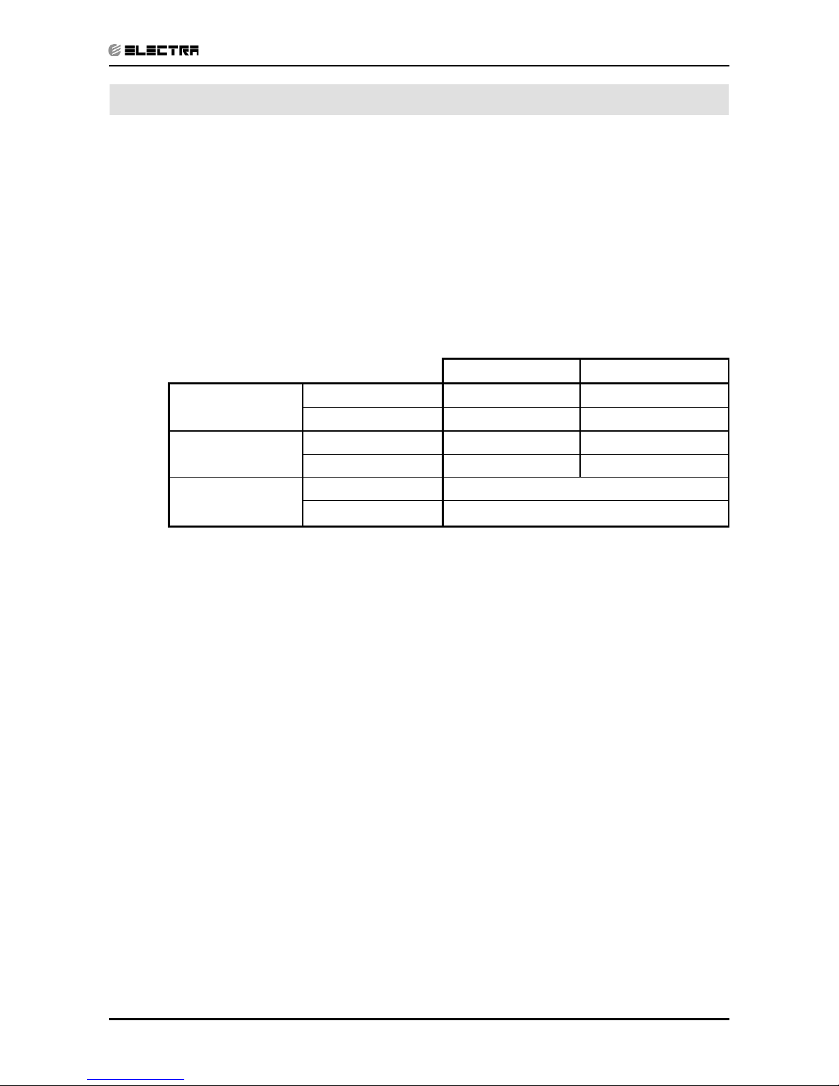
1.5 Matching Table
OUTDOOR UNITS
INDOOR UNITS
MODEL REFRIGERANT WNG 18 WNG 24
DUO 18+18 ST/RC R410A
√
DUO 24+24 ST/RC R410A
√
Page 5

2-1
PRODUCT DATA SHEET
Revision Y06-01Service Manual - DUO Series
2. PRODUCT DATA SHEET
2.1 DUO 18+18
Model Indoor Unit WNG 18+18
Model Outdoor Unit DUO 18+18 R410A RC
Installation Method of Pipe Flared
Characteristics Units Cooling Heating
Capacity
(4)
Btu/hr 18250*2 18600*2
kW 5.35*2 5.45*2
Power input
(4)
kW 3.32 3.32
EER (Cooling) or COP(Heating)
(4)
W/W 3.22 3.28
Energy efficiency class A C
Power supply V/Ph/Hz 220-240V/Single/50Hz
Rated current A 14.7 14.7
Starting current A 32 / 32
Circuit breaker rating A 30
INDOOR
Fan type & quantity Cross flow*1
Fan speeds H/M/L RPM 1200/1100/1000
Air flow
(1)
H/M/L m3/hr 890/800/700
External static pressure Min-Max Pa N/A
Sound power level
(2)
H/M/L dB(A) 57/54/52
Sound pressure level
(3)
H/M/L dB(A) 44/41/38
Moisture removal l/hr 2
Condenstate drain tube I.D mm 16
Dimensions WxHxD mm 1060x295x210
Weight kg 14
Package dimensions WxHxD mm 1125x360x280
Packaged weight kg 17
Units per pallet units 16
Stacking height units 8
OUTDOOR
Refrigerant control Capillary tube
Compressor type,model Rotary TOSHIBA PA200X2CS-4KU1
Fan type & quantity Propeller(direct) x 2
Fan speeds H/L RPM 780
Air flow H/L m3/hr 4500
Sound power level H/L dB(A) 70
Sound pressure level
(3)
H/L dB(A) 60
Dimensions WxHxD mm 950X1270X340
Weight kg 110
Package dimensions WxHxD mm 1110X1425X480
Packaged weight kg 130
Units per pallet Units 1
Stacking height units 1
Refrigerant type R410A
Refrigerant chargless distance kg/m 1.57kg/7.5m
Additional charge 4≤L≤10:+0g;10<L≤18:+230g;18<L≤25:+430g
Connections between
units
Liquid line In.(mm) 1/4”(6.35)
Suction line In.(mm) 1/2”(12.7)
Max.tubing length m. 25
Max.height difference m. 15
Operation control type Remote control
Heating elements kW
Others
(1)Airflow in ducted units;at nominal external static pressure.
(2)Sound power in ducted units is measured at air discharge.
(3)Sound pressure level measured at 1-meter distance from unit.
(4)Rating conditions in accordance to ISO 5151 and ISO 13253 (for ducted units).
Page 6
2-2
PRODUCT DATA SHEET
Revision Y06-01 Service Manual - DUO Series
2.2 DUO 24+24
Model Indoor Unit WNG 24+24
Model Outdoor Unit DUO 24+24 R410A RC
Installation Method of Pipe Flared
Characteristics Units Cooling Heating
Capacity
(4)
Btu/hr 22180*2 24230*2
kW 6.55*2 7.10*2
Power input
(4)
kW 4.65 4.81
EER (Cooling) or COP(Heating)
(4)
W/W 2.82 2.95
Energy efficiency class C D
Power supply V/Ph/Hz 220-240V/Single/50Hz
Rated current A 20.3 21.0
Starting current A 63 / 63
Circuit breaker rating A 30
INDOOR
Fan type & quantity Cross flow*1
Fan speeds H/M/L RPM 1300/1200/1100
Air flow
(1)
H/M/L m3/hr 910/820/740
External static pressure Min-Max Pa N/A
Sound power level
(2)
H/M/L dB(A) 60/57/55
Sound pressure level
(3)
H/M/L dB(A) 47/44/42
Moisture removal l/hr 2.8
Condenstate drain tube I.D mm 16
Dimensions WxHxD mm 1060x295x210
Weight kg 16
Package dimensions WxHxD mm 1125x360x280
Packaged weight kg 18
Units per pallet units 16
Stacking height units 8
OUTDOOR
Refrigerant control Capillary tube
Compressor type,model NN27VBAMT
Fan type & quantity Propeller(direct) x 2
Fan speeds H/L RPM 830
Air flow H/L m3/hr 4950
Sound power level H/L dB(A) 72
Sound pressure level
(3)
H/L dB(A) 61
Dimensions WxHxD mm 950X1270X340
Weight kg 110
Package dimensions WxHxD mm 1110X1425X480
Packaged weight kg 130
Units per pallet Units 1
Stacking height units 1
Refrigerant type R410A
Refrigerant chargless distance kg/m 2.15kg/7.5m
Additional charge 4≤L≤10:+0g;10<L≤15:+450g;15<L≤20:+580g
Connections between units
Liquid line In.(mm) 3/8”(9.53)
Suction line In.(mm) 5/8”(15.88)
Max.tubing length m. 20
Max.height difference m. 15
Operation control type Remote control
Heating elements kW
Others
(1)Airflow in ducted units;at nominal external static pressure.
(2)Sound power in ducted units is measured at air discharge.
(3)Sound pressure level measured at 1-meter distance from unit.
(4)Rating conditions in accordance to ISO 5151 and ISO 13253 (for ducted units).
Page 7
3-1
RATING CONDITIONS
Revision Y06-01Service Manual - DUO Series
3. RATING CONDITIONS
Standard conditions in accordance with ISO 5151, ISO 13253 (for ducted units)
and EN 14511.
Cooling:
Indoor: 27oC DB 19oC WB
Outdoor: 35 oC DB
Heating:
Indoor: 20oC DB
Outdoor: 7oC DB 6oC WB
3.1 Operating Limits
Indoor Outdoor
Cooling
Upper limit 32
o
C DB 23oC WB 46oC DB
Lower limit 21
o
C DB 15oC WB 21oC DB
Heating
Upper limit 27
o
C DB 24oC DB 18oC WB
Lower limit 20oC DB -9oC DB -10oC WB
Voltage
1PH 198 – 264 V
3PH 360 – 440 V
Page 8
4-1
OUTLINE DIMENSIONS
Revision Y06-01Service Manual - DUO Series
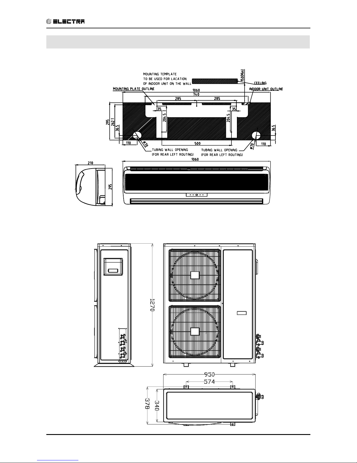
4. OUTLINE DIMENSIONS
4.1 Indoor Unit: WNG 18, 24
4.2 Outdoor Unit: DUO EDC 18+18, 24+24
Page 9
5-1
PERFORMANCE DATA & PRESSURE CURVES
Revision Y06-01Service Manual - DUO Series
5. PERFORMANCE DATA
5.1 DUO 18+18 (Unit 1 + Unit 2)
5.1.1 Cooling Mode at 7.5m Tubing Connection.
230V : Indoor Fan at High Speed.
Entering Air DB
OD Coil(oC)
Data
Entering Air WB/DB ID Coil(
o
C)
15/21 17/24 19/27 21/29 23/32
15
TC 11.28 11.68 11.96 12.24 12.43
SC 7.75 8.08 8.39 8.60 8.76
PI 2.36 2.37 2.37 2.38 2.39
20
TC 10.91 11.50 11.86 12.14 12.41
SC 7.59 8.00 8.34 8.58 8.74
PI 2.56 2.57 2.58 2.59 2.60
25
TC 10.32 11.15 11.72 12.07 12.37
SC 7.40 7.85 8.28 8.52 8.67
PI 2.77 2.79 2.81 2.83 2.85
30
TC 9.66 10.51 11.36 11.76 12.11
SC 7.16 7.62 8.10 8.33 8.49
PI 2.99 3.03 3.06 3.08 3.11
35
TC 8.94 9.70 10.70 11.24 11.77
SC 6.81 7.30 7.91 8.14 8.30
PI 3.22 3.28 3.33 3.36 3.37
40
TC 8.13 8.85 9.66 10.56 11.10
SC 6.42 6.91 7.48 7.72 7.88
PI 3.48 3.53 3.59 3.63 3.67
46
TC 7.05 7.71 8.48 9.37 10.10
SC 5.92 6.34 6.82 7.06 7.22
PI 3.80 3.86 3.94 4.00 4.04
LEGEND
TC – Total Cooling Capacity, kW
SC – Sensible Capacity, kW
PI – Power Input, kW
WB – Wet Bulb Temp., (oC)
DB – Dry Bulb Temp., (oC)
ID – Indoor
OD – Outdoor
Page 10
5-2
PERFORMANCE DATA & PRESSURE CURVES
Revision Y06-01 Service Manual - DUO Series
5.1.2 Heating Mode at 7.5m Tubing Connection.
230V : Indoor Fan at High Speed.
ENTERING AIR DB ID COIL(OC)
15 20 25
ENTERING WB
OD COIL(
o
C)
TH Pl TH Pl TH Pl
-10 5.72 2.66 5.50 2.83 5.29 2.97
-7 6.16 2.72 5.94 2.87 5.72 3.03
-2 6.54 2.76 6.32 2.92 6.10 3.09
2 7.96 2.89 7.63 3.07 7.30 3.25
6 11.23 3.10 10.90 3.32 10.52 3.53
10 12.21 3.28 11.88 3.50 11.55 3.75
15 13.19 3.42 12.86 3.69 12.54 3.92
20 13.90 3.52 13.57 3.82 13.19 4.12
LEGEND
TH – Total Heating Capacity, kW
PI – Power Input, kW
WB – Wet Bulb Temp., (oC)
DB – Dry Bulb Temp., (oC)
ID – Indoor
OD – Outdoor
Page 11

5-3
PERFORMANCE DATA & PRESSURE CURVES
Revision Y06-01Service Manual - DUO Series
5.2 Pressure Curves.
5.2.1 DUO 18+18 (Unit 1 + Unit 2)
5.2.2 Cooling.
Discharge Pressure VS.Outdoor Temp
10
12
14
16
18
20
22
24
26
28
30
32
34
36
38
40
15 20 25 30 35 40 46
Outdoor Temp.(DB oC )
Discharge Pressure (Bar[g])
15/21(WB/DB ºC)
17/24(WB/DB ºC)
19/27(WB/DB ºC)
21/29(WB/DB ºC)
23/32(WB/DB ºC)
Suction Pressure VS.Outdoor Temp
5.0
6.0
7.0
8.0
9.0
10.0
11.0
12.0
15 20 25 30 35 40 46
Outdoor Temp.(DB oC )
Suction Pressure (Bar[g])
15/21(WB/DB ºC)
17/24(WB/DB ºC)
19/27(WB/DB ºC)
21/29(WB/DB ºC)
23/32(WB/DB ºC)
Page 12

5-4
PERFORMANCE DATA & PRESSURE CURVES
Revision Y06-01 Service Manual - DUO Series
5.2.3 Heating.
Discharge Pressure VS.Outdoor Temp
16
18
20
22
24
26
28
30
32
34
36
38
-10 -5 0 5 10 15 20
Outdoor Temp.( WB oC )
Discharge Pressure(Bar[g])
25 DB (ºC)
20 DB (ºC)
15 DB (ºC)
Suction Pressure VS.Outdoor Temp
3.0
4.0
5.0
6.0
7.0
8.0
9.0
10.0
-10 -5 0 5 10 15 20
Outdoor Temp.( WB oC )
Suction Pressure(Bar[g])
15 DB (ºC)
20 DB (ºC)
25 DB (ºC)
Page 13

5-5
PERFORMANCE DATA & PRESSURE CURVES
Revision Y06-01Service Manual - DUO Series
5.3 DUO 24+24 (Unit 1 + Unit 2)
5.3.1 Cooling Mode at 7.5m Tubing Connection.
230V : Indoor Fan at High Speed.
Entering Air DB
OD Coil(oC)
Data
Entering Air WB/DB ID Coil(
o
C)
15/21 17/24 19/27 21/29 23/32
15
TC 13.81 14.30 14.64 14.98 15.21
SC 8.76 9.14 9.50 9.73 9.91
PI 3.30 3.30 3.31 3.32 3.33
20
TC 13.36 14.08 14.53 14.87 15.19
SC 8.59 9.06 9.44 9.71 9.89
PI 3.58 3.59 3.60 3.62 3.63
25
TC 12.64 13.65 14.35 14.78 15.14
SC 8.37 8.88 9.37 9.64 9.81
PI 3.87 3.89 3.92 3.95 3.97
30
TC 11.82 12.87 13.90 14.40 14.83
SC 8.11 8.62 9.16 9.43 9.61
PI 4.17 4.23 4.27 4.30 4.34
35
TC 10.94 11.88 13.10 13.76 14.41
SC 7.71 8.26 8.95 9.21 9.39
PI 4.50 4.58 4.65 4.69 4.71
40
TC 9.95 10.83 11.82 12.93 13.59
SC 7.27 7.82 8.47 8.74 8.91
PI 4.86 4.93 5.01 5.08 5.13
46
TC 8.63 9.44 10.38 11.47 12.36
SC 6.69 7.17 7.72 7.99 8.17
PI 5.30 5.38 5.51 5.58 5.65
LEGEND
TC – Total Cooling Capacity, kW
SC – Sensible Capacity, kW
PI – Power Input, kW
WB – Wet Bulb Temp., (oC)
DB – Dry Bulb Temp., (oC)
ID – Indoor
OD – Outdoor
Page 14

5-6
PERFORMANCE DATA & PRESSURE CURVES
Revision Y06-01 Service Manual - DUO Series
5.3.2 Heating Mode at 7.5m Tubing Connection.
230V : Indoor Fan at High Speed.
ENTERING AIR DB ID COIL(OC)
15 20 25
ENTERING WB
OD COIL(
o
C)
TH Pl TH Pl TH Pl
-10 7.46 3.88 7.17 4.13 6.89 4.34
-7 8.02 3.98 7.74 4.20 7.46 4.42
-2 8.52 4.03 8.24 4.27 7.95 4.51
2 10.37 4.22 9.94 4.49 9.51 4.75
6 14.63 4.53 14.20 4.85 13.70 5.15
10 15.90 4.79 15.48 5.12 15.05 5.47
15 17.18 5.00 16.76 5.38 16.33 5.72
20 18.11 5.14 17.68 5.58 17.18 6.01
LEGEND
TH – Total Heating Capacity, kW
PI – Power Input, kW
WB – Wet Bulb Temp., (oC)
DB – Dry Bulb Temp., (oC)
ID – Indoor
OU – Outdoor
Page 15

5-7
PERFORMANCE DATA & PRESSURE CURVES
Revision Y06-01Service Manual - DUO Series
5.4 Pressure Curves.
5.4.1 DUO 24+24 (Unit 1 + Unit 2)
5.4.2 Cooling.
Discharge Pressure VS.Outdoor Temp
10
12
14
16
18
20
22
24
26
28
30
32
34
36
38
40
15 20 25 30 35 40 46
Outdoor Temp.(DB oC )
Discharge Pressure (Bar[g])
15/21(WB/DB ºC)
17/24(WB/DB ºC)
19/27(WB/DB ºC)
21/29(WB/DB ºC)
23/32(WB/DB ºC)
Suction Pressure VS.Outdoor Temp
5.0
6.0
7.0
8.0
9.0
10.0
11.0
12.0
15 20 25 30 35 40 46
Outdoor Temp.(DB oC )
Suction Pressure (Bar[g])
15/21(WB/DB ºC)
17/24(WB/DB ºC)
19/27(WB/DB ºC)
21/29(WB/DB ºC)
23/32(WB/DB ºC)
Page 16

5-8
PERFORMANCE DATA & PRESSURE CURVES
Revision Y06-01 Service Manual - DUO Series
5.4.3 Heating.
Discharge Pressure VS.Outdoor Temp
16
18
20
22
24
26
28
30
32
34
36
38
40
42
44
-10 -5 0 5 10 15 20
Outdoor Temp.( WB oC )
Discharge Pressure(Bar[g])
25 DB (ºC)
20 DB (ºC)
15 DB (ºC)
Suction Pressure VS.Outdoor Temp
3.0
4.0
5.0
6.0
7.0
8.0
9.0
10.0
-10 -5 0 5 10 15 20
Outdoor Temp.( WB oC )
Suction Pressure(Bar[g])
15 DB (ºC)
20 DB (ºC)
25 DB (ºC)
Page 17

6-1
SOUND LEVEL CHARACTERISTICS
Revision Y06-01Service Manual - DUO Series
6. SOUND LEVEL CHARACTERISTICS
6.1 Outdoor Units
6.2 Sound Pressure Level Spectrum
(Measured as drawing)
DUO EDC 18+18 Cooling DUO EDC 18+18 Heating
Drawing of microphon position
Mic.
Unit
Ground
DUO EDC 24+24 Cooling DUO EDC 24+24 Heating
Page 18

7-1
ELECTRICAL DATA
Revision Y06-01Service Manual - DUO Series
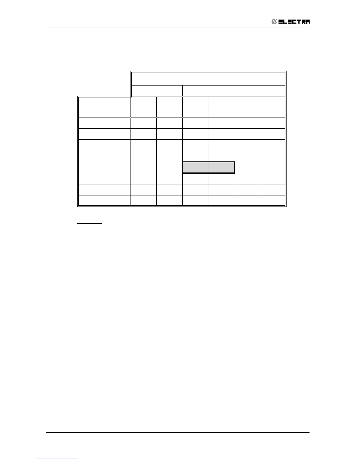
7. ELECTRICAL DATA
7.1 DUO EDC 18+18
Power Supply 1 PH, 220-240 VAC, 50Hz
Connected to Outdoor
Starting Current 32 / 32 A
Circuit breaker 30 A
Power supply wiring - No. x cross section 3 X 2.5 mm
2
Interconnecting cable - No. x cross section 6 X 1.5 mm
2
7.2 DUO EDC 24+24
Power Supply 1 PH, 220-240 VAC, 50Hz
Connected to Outdoor
Starting Current 63 / 63 A
Circuit breaker 30 A
Power supply wiring - No. x cross section 3 X 2.5 mm
2
Interconnecting cable - No. x cross section 6 X 1.5 mm
2
NOTE
Power wiring cord should comply with local laws and electrical
regulations requirements.
Page 19

8-1
WIRING DIAGRAMS
Revision Y06-01Service Manual - DUO Series
8. WIRING DIAGRAMS
8.1 DUO EDC 18+18, 24+24
468600026/01
LEGEND:
BK-Black BU-Blue
BN-Brown OG-Orange
RD-Red WH-White
GN/YE-Yellow/Green
Cap.1
CAP.--Capacitor
COMP.--Compressor
GN/YE
FM
Fan Motor
Housing
FM
GN/YE
OG
Deicer
OFAN_2
2.6
BU
RV1
RV2
4-way valve2
Transmit
4-way valvel
BU
N
BUBU
N
BU
Secondary coil
BU
UNIT 1
N
UNIT 2
OG
BN
BK
RV_1
OFAN_1
COMP_1
OG
BK
BN
BU
COMP_2
RV_2
N
RD
BN
BN
BU
0
4
CM
R
C
Comp.1
RD
2
Cap.1
RD
BU
S
RD
1
6
BN
KM
CONTACTOR1
RD
8
UNIT 1
O.U.Terminal 1
GN/YE
GN/YE
RD
Comp.
Heater1
BU
l
OG
Comp. Heater2
BU
RD
2
BU
O.U.Terminal 2
1.6
BN
1.5
1.4
1.N
L1
OG
BK
BN
BU
RD
UNIT 2
GN/YE
2.5
2.N
2.4
L2
GN/YE
BK
BN
BU
RD
I.U.Terminal 1
I.U.Terminal 2
INDOOR UNIT 1
6
5
4
N
L
L
INDOOR UNIT 2
5
6
N
4
BN
BUBU
BN
R
Terminal
RD
OG
RD
WH
WH
Cap.2
OG
AC9V
BU
L
N
Power Supply
BU
BK
POWER CABLE
230V/1Ph/50Hz
OG
Bu
1
2
C2
C1
If indoor unit with electronic heater,
the cables should be enlarged specifications.
CHANGE CABLE
power terminal
BU
RD
BU
Cap.2
0
Comp.2
BN
S
CM
C
BN
4
RD
2
1
KM
BN
CONTACTOR 2
RD
RD
6
8
GN/YE
OG
BK
BK
REMARKS
GN/YE
L
N
BN
BU
L1
L2
L3
no change
Multi Outdoor Unit
CABlE
unit£÷mm2
NAME
C
CABLE
CHANG CABLE
C2
C1
POWER CABLE
1.5
1.0
CABKE SPECIFICATIONS
2.52.5
1.51.5
BU
GN/YE
1.5
2.5
1.51.5
RD
OG
GN
1.5
0.75
BK
OFAN_1 OFAN_2NN
OTC1 OTC2
OTC_2OTC_1
COMP_1 COMP_2
Red
AC13.5V
YE
YEWHWH
YEYEWH
WH
Housing
Fan Motor
BU
BU
Page 20

9-1
ELECTRICAL CONNECTIONS
Revision Y06-01Service Manual - DUO Series
9. ELECTRICAL CONNECTIONS
9.1 DUO EDC 18+18, 24+24
Page 21

10-1
REFRIGERATION DIAGRAMS
Revision Y06-01Service Manual - DUO Series
10. REFRIGERATION DIAGRAMS
10.1 DUO EDC 18+18, 24+24
Page 22

11-1
TUBING CONNECTIONS
Revision Y06-01Service Manual - DUO Series
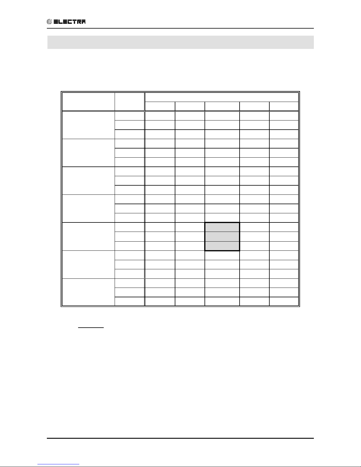
11. TUBING CONNECTIONS
TUBE (Inch)
TORQUE (Nm)
¼” ⅜” ½” ⅝” ¾”
Flare Nuts 11-13 40-45 60-65 70-75 80-85
Valve Cap 13-20 13-20 18-25 18-25 40-50
Service Port Cap 11-13 11-13 11-13 11-13 11-13
1. Valve Protection Cap-end
2. Refrigerant Valve Port (use Allen wrench to open/close)
3. Valve Protection Cap
4. Refrigerant Valve
5. Service Port Cap
6. Flare Nut
7. Unit Back Side
8. Copper Tube
When the outdoor unit is installed above the indoor unit an oil trap is required every 5m along the suction
line at the lowest point of the riser. Incase the indoor unit is installed above the outdoor, no trap is
required.
Page 23

12-1
TROUBLESHOOTING
Revision Y06-01Service Manual - DUO Series
12. TROUBLESHOOTING
Page 24

12-2
TROUBLESHOOTING
Revision Y06-01 Service Manual - DUO Series
Page 25

13-1
EXPLODED VIEWS AND SPARE PARTS LISTS
Revision Y06-01Service Manual - DUO Series
13. EXPLODED VIEWS AND SPARE PARTS LISTS
13.1 Outdoor Unit: DUO EDC 18+18
Page 26

13-2
EXPLODED VIEWS AND SPARE PARTS LISTS
Revision Y06-01 Service Manual - DUO Series
13.2 Outdoor Unit: DUO EDC 18+18
No. Item Description Qty
1 4517144 FAN COVER PP+UV/GRILL A 2
2 4522238 Left front panel painted assy. 1
3 4517004 FAN D=450mm 2
4 4517740R MOTOR YYK60B-6 2
5 4519199 MOTOR KICKSTAND 1
6 464600018 Base Plate Painting Assy./Duo 18+18 1ph 1
7 4522129 Partion plate assy. 1
8 455000506 Compressor Capacitor With Screw 45uF (CBB65) 2
9 201019 Nut M8 2
10 232299 Indoor Sensor BLACK 2
11 4524176 Liqiud Valve(R410A) 2
12 461010008 Gas Valve 1/2” R410A 2
13 455000102 Double patch Capacitor for fan motor 3uF (CBB61S) 2
14 4522319 Terminal 1 (6 bit) 1
15 204107 Cable clip Nylon 3
16 4517048 TERMINAL BLOCK OF NUETRAL 1
17 4525695 control box 1
18 463600004 Capillary Assy. 1/Duo 18+18 2
19 452988800 Insulation for compressor PA215/240 2
20 4510677 Nut With Flange M8 -D=24 GB6187-86 6
21 4525867 Ccompressor cable assy (L=1500) 2
22 453089900 Compressor Assy.PA200X2CS-4KU1 2
23 4525681 Bbig handle 1
24 4521791 Right-back cabinet paint assy.(no handle) 1
25 461600011 4-Way Valve Assy. 1/Duo 18+18 R410A 1ph 1
26 4526522 FOUR-WAY VALVE R410A 2
27 4526589 4-Way Valve Coil FOR R410A 2
28 4524731 Back grille paint assy 1
29 462300027 Condenser Assy. 1/Duo 18+18 1
29 462300028 Condenser Assy.2/Duo 18+18 1
30 4517832 TOP COVER PAINT ASSY 1
31 4523141 Hexagon locked nut M10 2
32 4517772 Little Handle 1
33 4517834 RIGHT FRONT PANEL PAINT ASSY 1
34 4522320 Terminal 2 (6 bit) 1
35 4522322 Power supply terminal (6 bit) 1
36 4510859 Terminal block 1
37 461600012 4-Way Valve Assy. 2/Duo 18+18 R410A 1ph 1
38 4524577 Valve plate(trio 18+18 r407c) 1
39 4525784 Cconnect cable assy for contactor 2
40 4524907 Contactor (CJX9B-25S/01) 2
41 452988900 Heater for compressor for PA215/240 2
43 4525525 Drain plate 1
44 463150000 Manifold 1/Duo 18+18/1ph 1
45 4522221 Division capillary assy. 52+52(up) 1
46 4525816 Support foot painted assy 1
47 4526184 Deicer for trio unit (modle:COR251A) 1
48 463150001 Manifold 2/Duo 18+18/1ph 1
49 4522223 Division capillary assy. 52+52(down) 1
Page 27

13-3
EXPLODED VIEWS AND SPARE PARTS LISTS
Revision Y06-01Service Manual - DUO Series
13.3 Outdoor Unit: DUO EDC 24+24
Page 28

13-4
EXPLODED VIEWS AND SPARE PARTS LISTS
Revision Y06-01 Service Manual - DUO Series
13.4 Outdoor Unit: DUO EDC 24+24
No. Item Description Qty
1 4517144 FAN COVER PP+UV/GRILL A 2
2 4522238 Left front panel painted assy. 1
3 4517004 FAN D=450mm 2
4 4517740R MOTOR YYK60B-6 2
5 4519199 MOTOR KICKSTAND 1
6 464600011 Base Plate Painting Assy./Duo 24+24 1ph 1
7 4522129 Partion plate assy. 1
8 455000506 Compressor Capacitor With Screw 45uF (CBB65) 2
9 201019 Nut M8 2
10 232299 Indoor SensorBLACK 2
11 452630200 Liqiud Valve(R410A) 2
12 461010009 Gas Valve 1/2” R410A 2
13 455000104 Double patch Capacitor for fan motor 4uF (CBB61S) 2
14 4522319 Terminal 1 (6 bit) 1
15 204107 Cable clip Nylon 3
16 4517048 TERMINAL BLOCK OF NUETRAL 1
17 464220003 Control box 1
18 463600007 Capillary Assy. 1/Duo 24+24 2
19 452891300 Insulation for compressor NN27 2
20 4510677 Nut With Flange M8 -D=24 GB6187-86 6
21 4525867 Compressor cable assy (L=1500) 2
22 452864700 Compressor Assy.NN27VBAMT assy. for GC24RC R410A 2
23 4525681 Big handle 1
24 4521791 Right-back cabinet paint assy.(no handle) 1
25 461600008 4-Way Valve Assy. 1/Duo 24+24 R410A 1ph 1
26 4526522 FOUR-WAY VALVE R410A 2
27 4526589 4-Way Valve Coil FOR R410A 2
28 4524731 Back grille paint assy 1
29 470660016 Condenser Assy.1/Duo 24+24 1
29 470660017 Condenser Assy.2/Duo 24+24
30 4517832 TOP COVER PAINT ASSY 1
31 4523141 Hexagon locked nut M10 2
32 4517772 Little Handle 1
33 4517834 RIGHT FRONT PANEL PAINT ASSY 1
34 4522320 Terminal 2 (6 bit) 1
35 4522322 Power supply terminal (6 bit) 1
36 4510859 Terminal block 1
37 461600009 4-Way Valve Assy. 2 1
38 4524577 Valve plate(trio 18+18 r407c) 1
39 467030022 Connect cable assy for contactor 2
40 452872000 Contactor (GC3-18S/01TKKH) 2
41 4520870 Heater for compressor for PA215/240 2
42 4523291 Soft-starter 1
43 4525525 Drain plate 1
44 463150002 Manifold 1/Duo 24+24/1ph 1
45 463700006 Distributing Pipe Assy. 1
46 4525816 Support foot painted assy 1
47 4526184 Deicer for trio unit (modle:COR251A) 1
48 463150003 Manifold 2/Duo 24+24/1ph 1
49 463700007 Distributing Pipe Assy. 1
Page 29

14-1
APPENDIX A
Revision Y06-01
Service Manual - DUO Series
APPENDIX A
INSTALLATION AND OPERATION MANUAL
► INSTALLATION INSTRUCTION
Page 30

Page 31

 Loading...