

Page 1
Service Manual
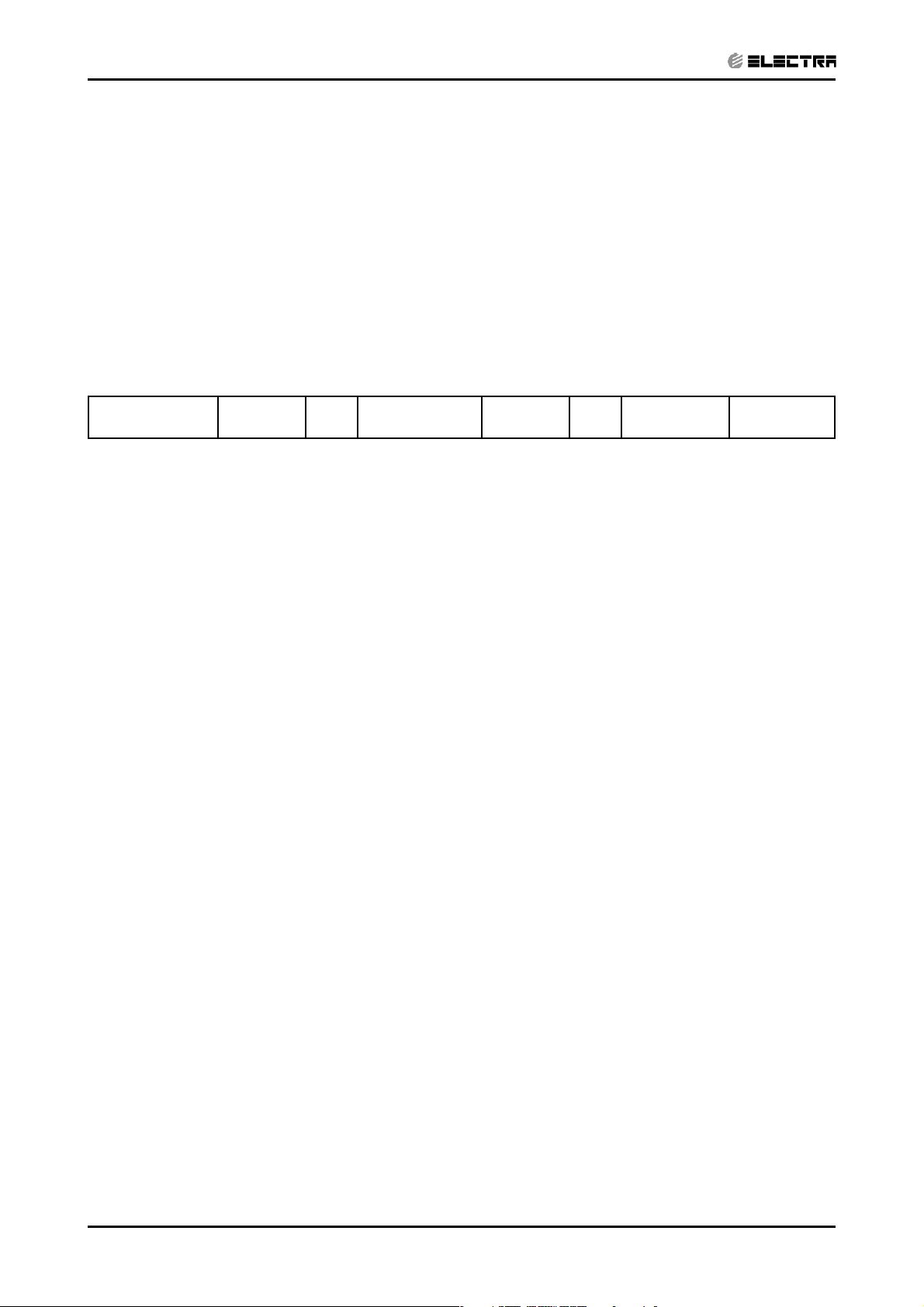
DNG series
Indoor Units Outdoor Units
DNG 18 GC18
DNG 24 OU7-24
DNG 30 OU8-30
DNG 37 OU10-36
DNG 44 OU10-44
REFRIGERANT
R410A
FEBRUARY 2005
HEAT PUMP
COOLING ONLY
Page 2
LIST OF EFFECTIVE PAGES
LIST OF EFFECTIVE PAGES
Note: Changes in the pages are indicated by a “Revision#” in the footer of each effected page
(when none indicates no changes in the relevant page). All pages in the following list represent
effected/ non effected pages divided by chapters.
Dates of issue for original and changed pages are:
Original ....... 0 ........ 24 February 2005
Total number of pages in this publication is 139 consisting of the following:
Page
No.
Title ....................... 0
A ........................... 0
i ............................. 0
1-1 - 1-4 ................ 0
2-1 - 2-4 ................ 0
3-1 - 3-2 ................ 0
4-1 - 4-2 ................ 0
5-1 - 5-12 .............. 0
6-1 - 6-8 ................ 0
7-1 - 7-2 ................ 0
8-1 - 8-2 ................ 0
9-1 - 9-2 ................ 0
10-1-10-2 .............. 0
• Zero in this column indicates an original page.
Revision
No. #
Page
No.
Revision
No. #
Page
No.
Revision
No. #
*Due to constant improvements please note that the data on this service manual can be modified with out notice.
**Photos are not contractual.
A
Revision Y05-01
DATA BOOK - DNG Series
Page 3

TABLE OF CONTENTS
Table of Contents
1. INTRODUCTION ...................................................................................................1-1
2. PRODUCT DATA SHEET ......................................................................................2-1
3. RATING CONDITIONS ..........................................................................................3-1
4. OUTLINE DIMENSIONS .......................................................................................4-1
5. PERFORMANCE DATA & PRESSURE CURVES ................................................5-1
6. AIRFLOW CURVES ..............................................................................................6-1
7. SOUND LEVEL CHARACTERISTICS ..................................................................7-1
8. ELECTRICAL DATA ..............................................................................................8-1
9. WIRING DIAGRAMS .............................................................................................9-1
10. ELECTRICAL CONNECTIONS .............................................................................10-1
11. REFRIGERATION DIAGRAMS .............................................................................11-1
12. TUBING CONNECTIONS ......................................................................................12-1
13. CONTROL SYSTEM .............................................................................................13-1
14. TROUBLESHOOTING ..........................................................................................14-1
15. EXPLODED VIEWS AND SPARE PARTS LISTS .................................................15-1
16. APPENDIX A .........................................................................................................16-1
Service Manual - DNG Series
Revision Y05-01
i
Page 4
1. INTRODUCTION
CONTENT
1.1 General
The new DNG ducted split unit range comprises the ST (cooling only) as well as RC
(heat pump) models, it is available at 1PH, 3PH as follow:
• 1PH DNG 18, 24, 30, 37
• 3PH DNG 18, 24, 30, 37, 44
Remote control compatibility
• The DNG unit is compatible with remote controls RC3, RC4, RCW1, RCW2
1.2 Main Features
INTRODUCTION
The DNG series benefits from the most advanced technological innovations, namely:
• R410A refrigerant for all the range.
• The only Single Fan, medium capacity, low silhouette ducted unit
• High Static Pressure in the low silhouette category.
• Low indoor and outdoor sound level
• Low Silhouette 260-300mm height that simplify the false ceiling construction.
• Small volume, easy for installation (require small space for installation)
• Water drainage capability without siphon near the unit.
• Built in over-flow protection against condensate water
• 50 meters pipes installation in charge-less system
• High COP by switching to R 410A and enlarging indoor coil sizes
• Complies with M1 regulations
• Compatible with Saginomya “all season kit” that permits operation in cooling
mode up to -5ºC outdoor temperature.
• Easy service access by removing the drain pan.
• Microprocessor control.
• Infrared remote control with liquid crystal display.
Revision Y05-01Service Manual - DNG Series
1-1
Page 5

INTRODUCTION
CONTENT
1.3 Indoor Unit
The indoor unit can fit easily to many types of residential and commercials applications.
It includes:
• High technology plastic fan and fan housing.
• A drain pool that is under the entire unit with internal downward slope.
• An over-flow switch that stops compressor operation in case drainage tube is
blocked.
• A bended coil with treated aluminium fins.
• 3-speed fan motor with internal protection with extra speed for higher external
static pressure.
• Advanced electronic control box assembly with 1.8-meter cable to allow
installation at a more accessible area.
• All the tubing connections are in the back of the unit to allow easy outlet to left
or right side of the unit.
• Field options:
(1) Electrical Heaters for 2005
(2) External water pump
(3) Airconet connection
(4) Plenum kit for connection of flexible hoses at air outlet.
1.4 Filtration
• The unit is equipped with pre-filters.
• Easy and versitile access, rear or buttom, can be easily adjusted by the
installer.
1.5 Ioniser (Optional)
A special design Ioniser protected by unique patents integrated into the indoor unit,
generating negative ions to the room providing comfort and upgraded indoor air quality.
1.6 Control
The microprocessor indoor controller, and an infrared remote control, supplied as
standard, provides complete operating function and programming. For further details,
please refer to the Operation Manual,
1-2
Revision Y05-01 Service Manual - DNG Series
Page 6
1.7 Outdoor Unit
CONTENT
The DNG outdoor units can be installed as floor or wall mounted units by using a
wall-supporting bracket. The metal sheets are protected by anti- corrosion paintwork
allowing long life resistance. All outdoor units are pre-charged. For further information,
please refer to the Product Data Sheet, Chapter 2.
It includes:
• Compressor mounted in a soundproofed compartment :
Rotary – for DNG 18, 24, 30, 37
Scroll – for DNG 44
• Improved 3- blades axial fans for noise reduction.
• Outdoor coil with hydrophilic fins for RC units optimised for operation with R
410A refrigerant.
• Fan grill air outlet.
INTRODUCTION
• Service valves” flare” type connection.
• Service ports for high/ low pressure measurement.
• Interconnecting wiring terminal block.
1.8 Tubing Connections
Flare type-interconnecting tubing to be produced on site.
All the units from 7KW and up can be installed with 50-meter pipe length and 25 meter
height difference without oil traps.
For further details, please refer to the Installation Manual.
1.9 Accessories
ASK (All Season Kit):
For low ambient working conditions in cooling, an ASK can be installed inside the
outdoor unit. This kit allows cooling operation down to outdoor temperature of -10 ºC by
gradually controlling the outdoor fan speed motor.
RCW Wall Mounted Remote Control
The RCW remote control is mounted on the wall, and controls the unit either as an
infrared remote control or as a wired controller. The wired controller can control up to
10 Indoor units with the same program settings and adjustments.
For further details, please refer to the Technical Service Manual.
1.10 Inbox Documentation
Each unit includes its own installation and operation manuals.
Revision Y05-01Service Manual - DNG Series
1-3
Page 7
2. PRODUCT DATA SHEET
CONTENT
2.1 R410C
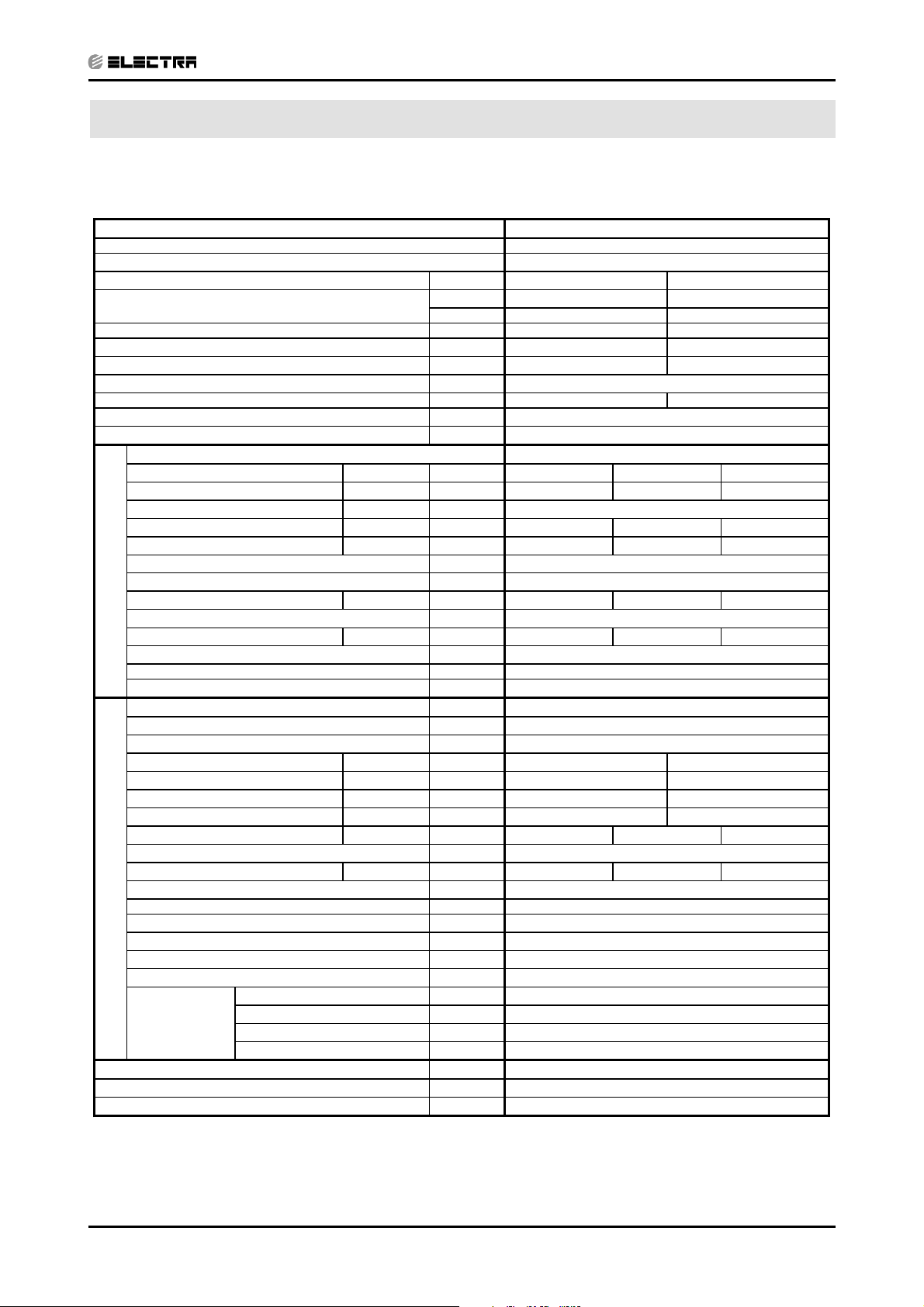
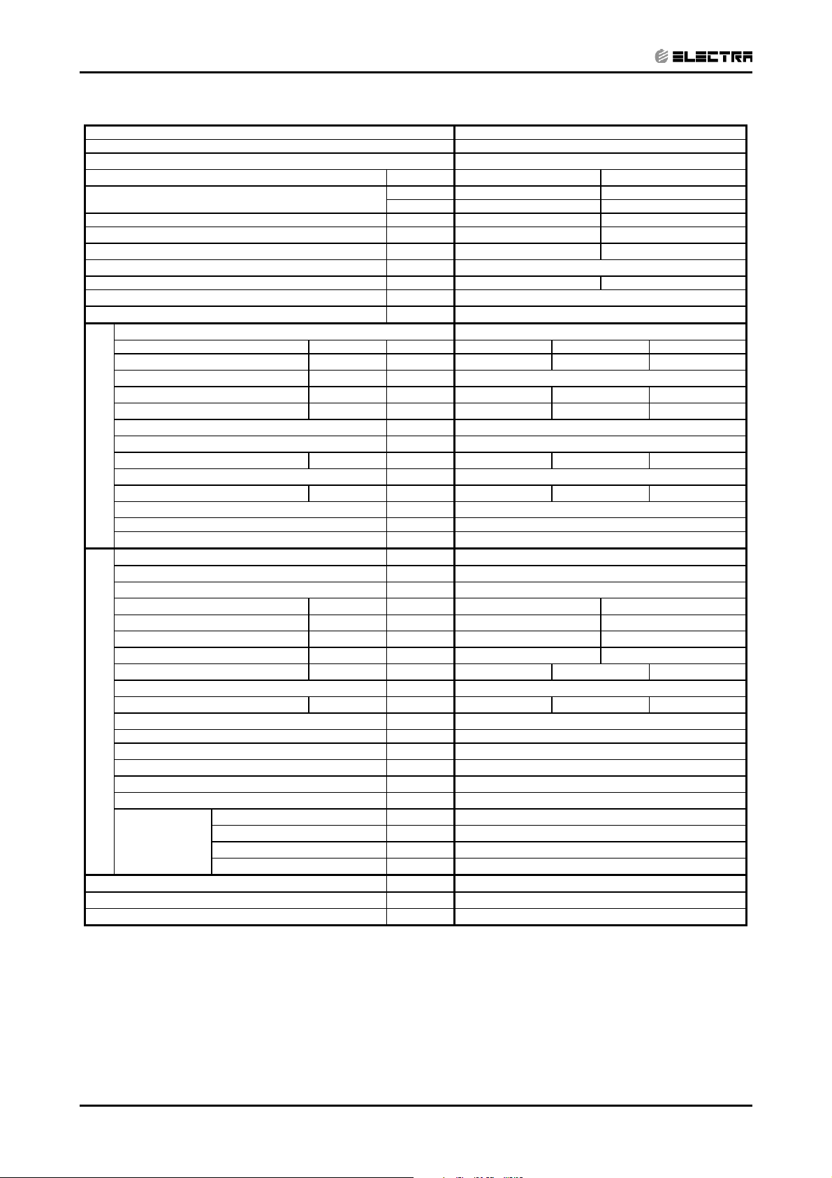
PRODUCT DATA SHEET
Model Indoor Unit
Model Outdoor Unit GC 18 R410A
Installation Method DUCTED
Characteristics Units Cooling Heating
Capacity
Power Input
COP
Energy Efficiency Class B D
Power Supply V/Ph/Hz 230/50/1
Rated Current A 8.2 7.5
Starting Current A 43
Circuit Breaker Rating A 20
Operation Control Type
Heating Elements kW
Others
(1)
(1)
(1)
INDOOR
OUTDOOR
kW 1.8 1.7
W/W 3.05 3.12
Fan Type & Quantity
Fan Speed H/M/L RPM 630 530 425
(2)
Airflow
H/M/L m3/hr 1150 875 730
External Static Pressure Min-Max Pa 25-60
Sound Power Level
Sound Pressure Level
Moisture Removal L/hr 2.0
Condensate Drain Tube I.D. mm 22
Dimensions W/H/D mm 770 260 690
Weight kg 29
Package Dimensions W/H/D mm 959 315 854
Packaged Weight kg 31
Units per Pallet Units 6
Stacking Height Units 6
Refrigerant Control
Compressor Type, Model Rotary
Fan Type & Quantity Axial & 1
Fan Speeds H/L RPM 815
Airflow H/L m3/hr 2480
Sound Power Level H/L dB (A) 68
Sound Pressure Level
Dimensions W/H/D mm 846 690 302
Weight kg 56
Package Dimensions W/H/D mm 990 770 430
Packaged Weight kg 61
Units per Pallet Units 9
Stacking Height Units 3
Refrigerant Type R 410A
Refrigerant Chargeless Distance kg/m 1.75/10
Additional Charge Per 1 Meter g/m 25
Connections
Between Units
(3)
H/M/L dB (A) 55 53 50
(4)
H/M/L dB (A) 45 42 40
(4)
H/L dB (A) 58
Liquid Line In 1/4
Suction Line In 1/2
Max. Tubing Length m 25
Max. Height Difference m 15
Btu/hr 19100 18000
kW 5.6 5.3
DNG 18
CENTRIFUGAL X1
Capillary
LCD Remote Control
1) Rating conditions in accordance with ISO 5151 and ISO 13253 (for ducted units) and EN14511.
(2) Airflow in ducted units; at nominal external static pressure.
(3) Sound power in ducted units is measured at air discharge.
(4) Sound pressure level measured at 1 meter distance from unit.
Revision Y05-01Service Manual - DNG Series
2-1
Page 8
PRODUCT DATA SHEET
CONTENT
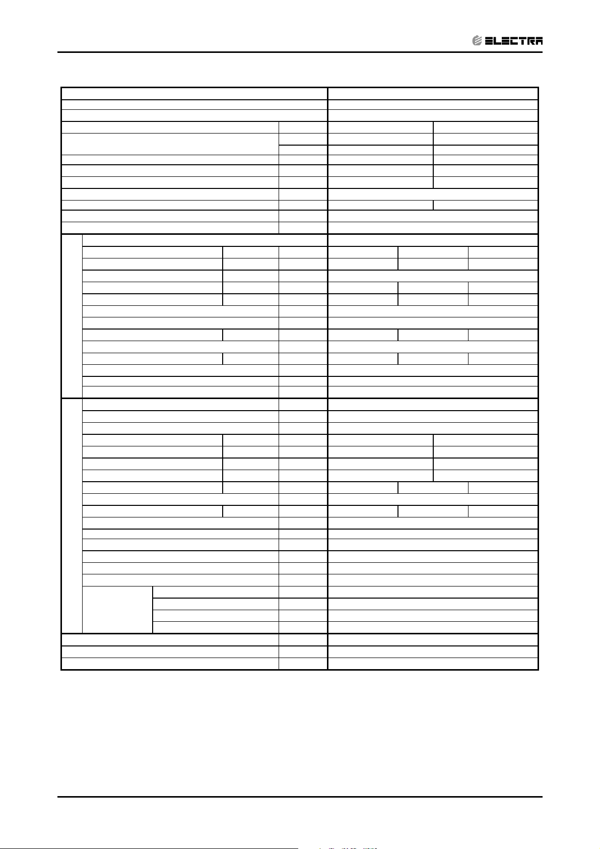
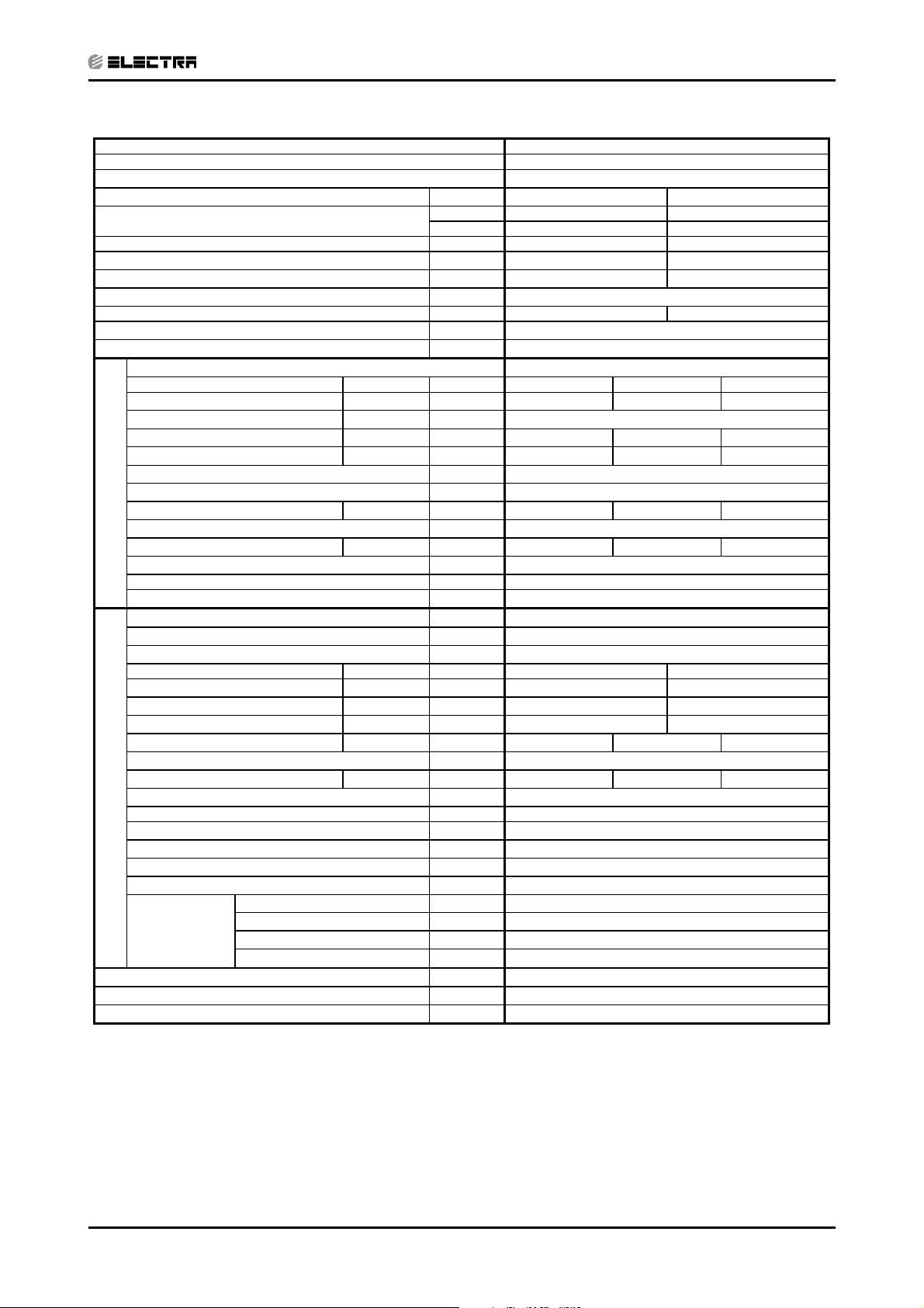
Model Indoor Unit
DNG 18
Model Outdoor Unit GC 18 3PH R410A
Installation Method DUCTED
Characteristics Units Cooling Heating
Capacity
Power Input
COP
(1)
(1)
(1)
kW 1.8 1.7
W/W 3.05 3.12
Btu/hr 19100 18000
kW 5.6 5.3
Energy Efficiency Class B D
Power Supply V/Ph/Hz 400/50/1
Rated Current A 3*3.5 3*3.1
Starting Current A 26
Circuit Breaker Rating A 3*10
Fan Type & Quantity
Fan Speed H/M/L RPM 630 530 425
(2)
Airflow
H/M/L m3/hr 1150 875 730
External Static Pressure Min-Max Pa 25-60
Sound Power Level
Sound Pressure Level
(3)
H/M/L dB (A) 55 53 50
(4)
H/M/L dB (A) 45 42 40
CENTRIFUGAL X1
Moisture Removal L/hr 2.0
Condensate Drain Tube I.D. mm 22
INDOOR
Dimensions W/H/D mm 770 260 690
Weight kg 29
Package Dimensions W/H/D mm 959 315 854
Packaged Weight kg 31
Units per Pallet Units 6
Stacking Height Units 6
Refrigerant Control
Capillary
Compressor Type, Model Rotary
Fan Type & Quantity Axial & 1
Fan Speeds H/L RPM 815
Airflow H/L m3/hr 2480
Sound Power Level H/L dB (A) 68
Sound Pressure Level
(4)
H/L dB (A) 58
Dimensions W/H/D mm 846 690 302
Weight kg 56
Package Dimensions W/H/D mm 990 770 430
Packaged Weight kg 61
OUTDOOR
Units per Pallet Units 9
Stacking Height Units 3
Refrigerant Type R 410A
Refrigerant Chargeless Distance kg/m 1.98/10
Additional Charge Per 1 Meter g/m 25
Liquid Line In 1/4
Connections
Between Units
Suction Line In 1/2
Max. Tubing Length m 25
Max. Height Difference m 15
Operation Control Type
LCD Remote Control
Heating Elements kW
Others
1) Rating conditions in accordance with ISO 5151 and ISO 13253 (for ducted units) and EN14511.
(2) Airflow in ducted units; at nominal external static pressure.
(3) Sound power in ducted units is measured at air discharge.
(4) Sound pressure level measured at 1 meter distance from unit.
2-2
Revision Y05-01 Service Manual - DNG Series
Page 9
PRODUCT DATA SHEET
CONTENT
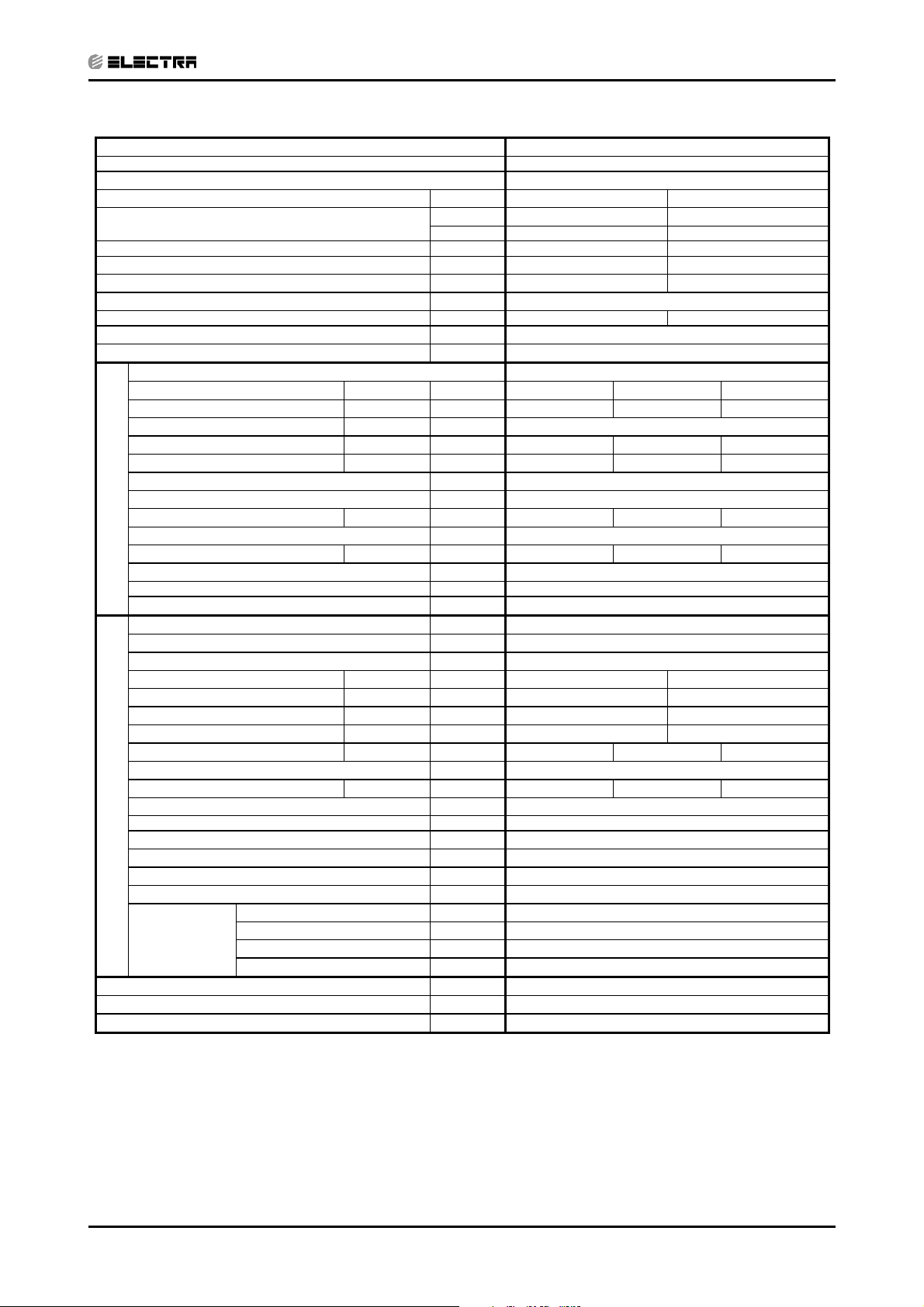
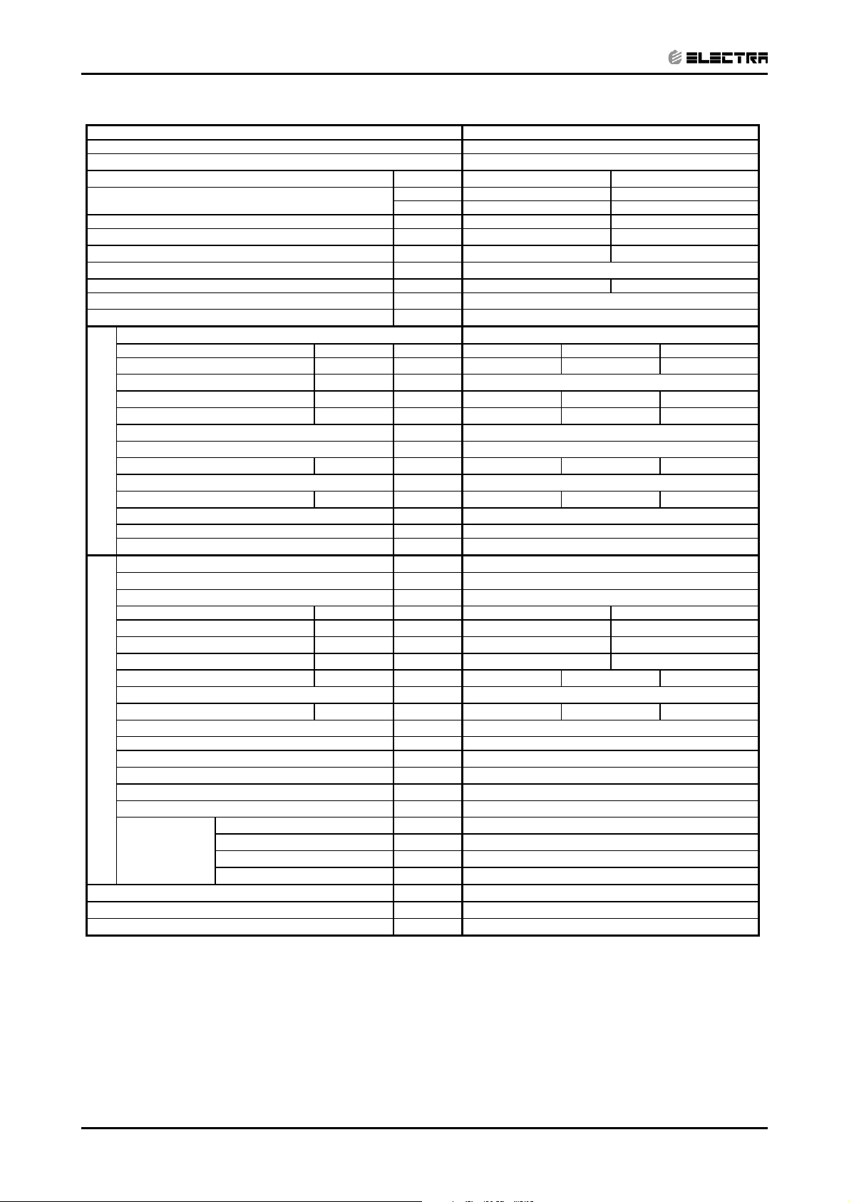
Model Indoor Unit
DNG 24
Model Outdoor Unit OU7-24 R410A
Installation Method DUCTED
Characteristics Units Cooling Heating
Capacity
Power Input
COP
(1)
(1)
(1)
kW 2.4 2.3
W/W 2.9 3.04
Btu/hr 23500 23850
kW 6.9 7.0
Energy Efficiency Class C D
Power Supply V/Ph/Hz 230/50/1
Rated Current A 10.8 10.5
Starting Current A 66
Circuit Breaker Rating A 20
Fan Type & Quantity
Fan Speed H/M/L RPM 680 630 530
(2)
Airflow
H/M/L m3/hr 1210 1100 840
External Static Pressure Min-Max Pa 25-60
Sound Power Level
Sound Pressure Level
(3)
H/M/L dB (A) 60 58 55
(4)
H/M/L dB (A) 48 45 43
CENTRIFUGAL X1
Moisture Removal L/hr 2.3
Condensate Drain Tube I.D. mm 22
INDOOR
Dimensions W/H/D mm 770 260 690
Weight kg 29
Package Dimensions W/H/D mm 959 315 854
Packaged Weight kg 31
Units per Pallet Units 6
Stacking Height Units 6
Refrigerant Control
Capillary
Compressor Type, Model Rotary
Fan Type & Quantity Axial & 1
Fan Speeds H/L RPM 850
Airflow
Sound Power Level H/L dB (A) 67
Sound Pressure Level
(4)
H/L dB (A) 58
H/L m
3
/hr 3100
Dimensions W/H/D mm 900 680 340
Weight kg 78
Package Dimensions W/H/D mm 985 730 435
Packaged Weight kg 82
OUTDOOR
Units per Pallet Units 6
Stacking Height Units 2
Refrigerant Type R 410A
Refrigerant Chargeless Distance kg/m 2,16/ 12.5
Additional Charge Per 1 Meter g/m 25
Liquid Line In 3/8
Connections
Between Units
Suction Line In 5/8
Max. Tubing Length m 50
Max. Height Difference m 25
Operation Control Type
LCD Remote Control
Heating Elements kW
Others Crankcase heater (50W)
1) Rating conditions in accordance with ISO 5151 and ISO 13253 (for ducted units) and EN14511.
(2) Airflow in ducted units; at nominal external static pressure.
(3) Sound power in ducted units is measured at air discharge.
(4) Sound pressure level measured at 1 meter distance from unit.
Revision Y05-01Service Manual - DNG Series
2-3
Page 10
PRODUCT DATA SHEET
CONTENT
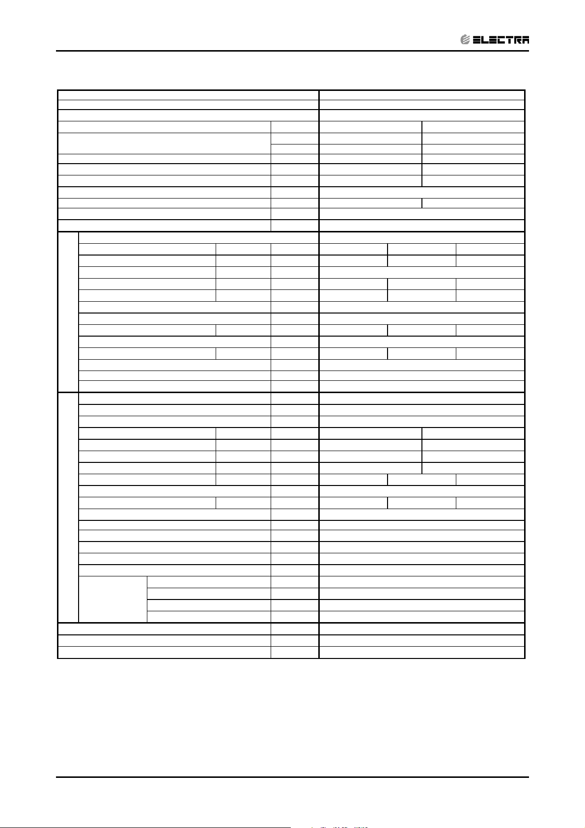
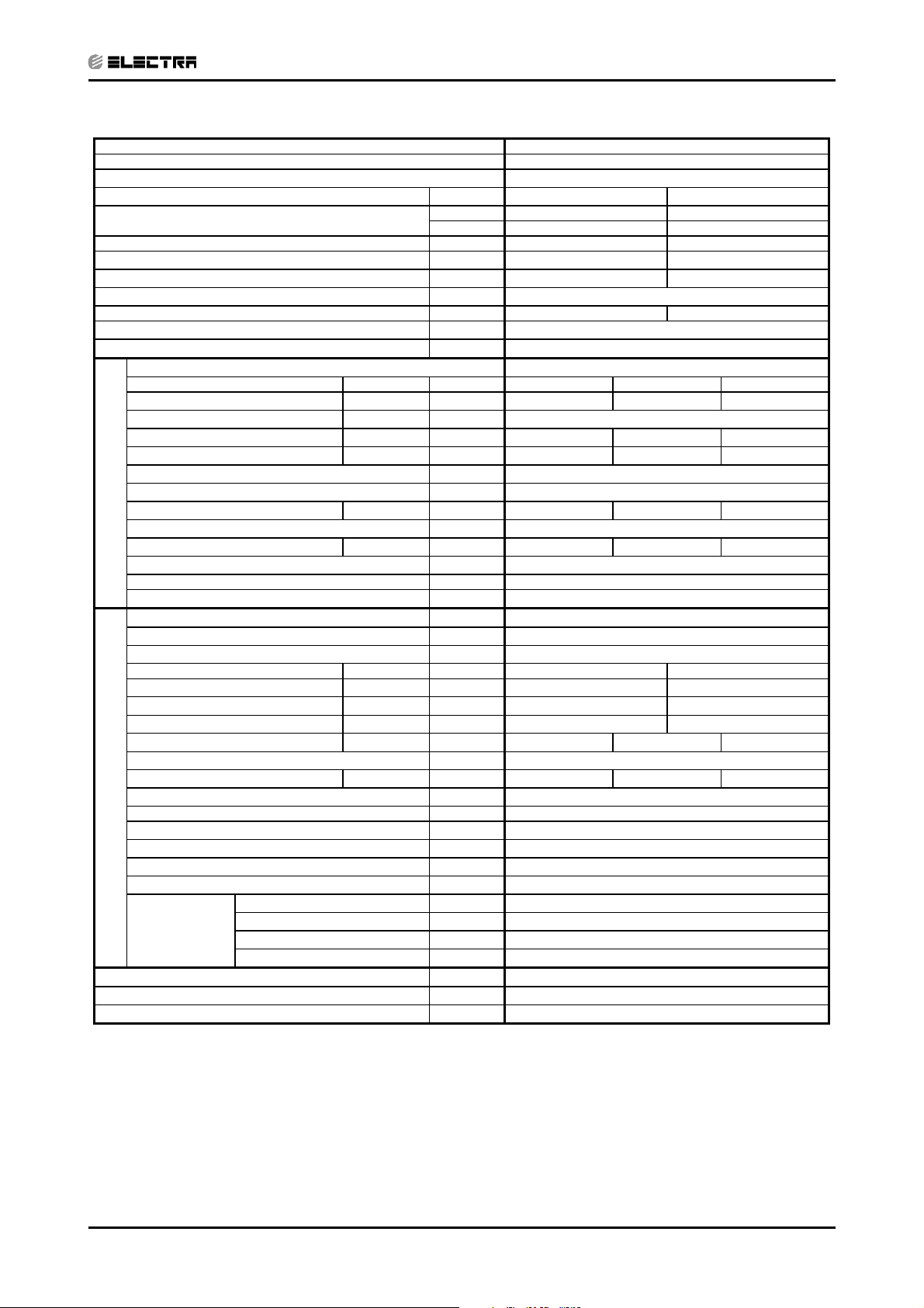
Model Indoor Unit DNG 24
Model Outdoor Unit OU7-24T R410A
Installation Method DUCTED
Characteristics Units Cooling Heating
Capacity
Power Input
COP
(1)
(1)
(1)
kW 2.4 2.3
W/W 2.9 3.03
Energy Efficiency Class C D
Power Supply V/Ph/Hz 400/50/3
Rated Current A 3*6.0 3*5.4
Starting Current A
Circuit Breaker Rating A 3*10
Fan Type & Quantity
Fan Speed H/M/L RPM 680 630 530
(2)
Airflow
H/M/L m3/hr 1210 1100 840
External Static Pressure Min-Max Pa 25-60
Sound Power Level
Sound Pressure Level
(3)
H/M/L dB (A) 60 58 55
(4)
H/M/L dB (A) 48 45 43
Moisture Removal L/hr 2.3
Condensate Drain Tube I.D. mm 22
INDOOR
Dimensions W/H/D mm 770 260 690
Weight kg 29
Package Dimensions W/H/D mm 959 315 854
Packaged Weight kg 31
Units per Pallet Units 6
Stacking Height Units 6
Refrigerant Control
Compressor Type, Model Rotary
Fan Type & Quantity Axial & 1
Fan Speeds H/L RPM 850
Airflow
Sound Power Level H/L dB (A) 67
Sound Pressure Level
(4)
H/L dB (A) 58
H/L m
Dimensions W/H/D mm 900 680 340
Weight kg 78
Package Dimensions W/H/D mm 985 730 435
Packaged Weight kg 82
OUTDOOR
Units per Pallet Units 6
Stacking Height Units 2
Refrigerant Type R 410A
Refrigerant Chargeless Distance kg/m 2,16/ 12.5
Additional Charge Per 1 Meter g/m 25
Liquid Line In 3/8
Connections
Between Units
Suction Line In 5/8
Max. Tubing Length m 50
Max. Height Difference m 25
Operation Control Type
Heating Elements kW
Others Crankcase heater (50W), 3 Phase Protector
Btu/hr 23500 23850
kW 6.9 7.0
CENTRIFUGAL X1
Capillary
3
/hr 3100
LCD Remote Control
1) Rating conditions in accordance with ISO 5151 and ISO 13253 (for ducted units) and EN14511.
(2) Airflow in ducted units; at nominal external static pressure.
(3) Sound power in ducted units is measured at air discharge.
(4) Sound pressure level measured at 1 meter distance from unit.
2-4
Revision Y05-01 Service Manual - DNG Series
Page 11

PRODUCT DATA SHEET
CONTENT
Model Indoor Unit DNG 30
Model Outdoor Unit OU8-30 R410A
Installation Method DUCTED
Characteristics Units Cooling Heating
Capacity
Power Input
COP
(1)
(1)
(1)
kW 3.0 2.8
W/W 2.81 3.22
Energy Efficiency Class C C
Power Supply V/Ph/Hz 230/50/1
Rated Current A 13.7 12.5
Starting Current A 80
Circuit Breaker Rating A 25
Fan Type & Quantity
Fan Speed H/M/L RPM 800 670 550
(2)
Airflow
H/M/L M3/hr 1420 1150 935
External Static Pressure Min-Max Pa 37-80
Sound Power Level
Sound Pressure Level
(3)
H/M/L dB (A) 64 61 58
(4)
H/M/L dB (A) 49 46 44
Moisture Removal L/hr 3.0
Condensate Drain Tube I.D. mm 22
INDOOR
Dimensions W/H/D mm 770 260 690
Weight kg 31
Package Dimensions W/H/D mm 959 315 854
Packaged Weight kg 33
Units per Pallet Units 6
Stacking Height Units 6
Refrigerant Control
Compressor Type, Model Rotary
Fan Type & Quantity Axial & 1
Fan Speeds H/L RPM 850
Airflow
Sound Power Level H/L dB (A) 66
Sound Pressure Level
(4)
H/L dB (A) 58
H/L M
Dimensions W/H/D mm 900 860 340
Weight kg 78
Package Dimensions W/H/D mm 985 907 435
Packaged Weight kg 82
OUTDOOR
Units per Pallet Units 6
Stacking Height Units 2
Refrigerant Type R 410A
Refrigerant Chargeless Distance kg/m 2.42/ 15
Additional Charge Per 1 Meter g/m 25
Liquid Line In 3/8
Connections
Between Units
Suction Line In 5/8
Max. Tubing Length m 50
Max. Height Difference m 25
Operation Control Type
Heating Elements kW
Others Crankcase heater (50W)
Btu/hr 29000 30700
kW 8.5 9.0
CENTRIFUGAL X1
Capillary
3
/hr 3150
LCD Remote Control
1) Rating conditions in accordance with ISO 5151 and ISO 13253 (for ducted units) and EN14511.
(2) Airflow in ducted units; at nominal external static pressure.
(3) Sound power in ducted units is measured at air discharge.
(4) Sound pressure level measured at 1 meter distance from unit.
Revision Y05-01Service Manual - DNG Series
2-5
Page 12
PRODUCT DATA SHEET
CONTENT
Model Indoor Unit DNG 30
Model Outdoor Unit OU8-30T R410A
Installation Method DUCTED
Characteristics Units Cooling Heating
Capacity
Power Input
COP
(1)
(1)
(1)
kW 3.0 2.8
W/W 2.82 3.24
Energy Efficiency Class C C
Power Supply V/Ph/Hz 400/50/3
Rated Current A 3*7.5 3*7.1
Starting Current A 35
Circuit Breaker Rating A 3*16
Fan Type & Quantity
Fan Speed H/M/L RPM 800 670 550
(2)
Airflow
H/M/L M3/hr 1420 1150 935
External Static Pressure Min-Max Pa 37-80
Sound Power Level
Sound Pressure Level
(3)
H/M/L dB (A) 64 61 58
(4)
H/M/L dB (A) 49 46 44
Moisture Removal L/hr 3.0
Condensate Drain Tube I.D. mm 22
INDOOR
Dimensions W/H/D mm 770 260 690
Weight kg 31
Package Dimensions W/H/D mm 959 315 854
Packaged Weight kg 33
Units per Pallet Units 6
Stacking Height Units 6
Refrigerant Control
Compressor Type, Model Rotary
Fan Type & Quantity Axial & 1
Fan Speeds H/L RPM 850
Airflow
Sound Power Level H/L dB (A) 66
Sound Pressure Level
(4)
H/L dB (A) 58
H/L M
Dimensions W/H/D mm 900 860 340
Weight kg 78
Package Dimensions W/H/D mm 985 907 435
Packaged Weight kg 82
OUTDOOR
Units per Pallet Units 6
Stacking Height Units 2
Refrigerant Type R 410A
Refrigerant Chargeless Distance kg/m 2.42/ 15
Additional Charge Per 1 Meter g/m 25
Liquid Line In 3/8
Connections
Between Units
Suction Line In 5/8
Max. Tubing Length m 50
Max. Height Difference m 25
Operation Control Type
Heating Elements kW
Others Crankcase heater (50W), 3 Phase Protector
Btu/hr 29000 30700
kW 8.5 9.0
CENTRIFUGAL X1
Capillary
3
/hr 3150
LCD Remote Control
1) Rating conditions in accordance with ISO 5151 and ISO 13253 (for ducted units) and EN14511.
(2) Airflow in ducted units; at nominal external static pressure.
(3) Sound power in ducted units is measured at air discharge.
(4) Sound pressure level measured at 1 meter distance from unit.
2-6
Revision Y05-01 Service Manual - DNG Series
Page 13
PRODUCT DATA SHEET
CONTENT
Model Indoor Unit DNG 37
Model Outdoor Unit OU10-36 R410A
Installation Method DUCTED
Characteristics Units Cooling Heating
Capacity
Power Input
COP
(1)
(1)
(1)
kW 3.8 3.7
W/W 2.81 3.05
Energy Efficiency Class C D
Power Supply V/Ph/Hz 230/50/1
Rated Current A 16.9 16.3
Starting Current A 92
Circuit Breaker Rating A 25
Fan Type & Quantity
Fan Speed H/M/L RPM 775 650 540
(2)
Airflow
H/M/L M3/hr 1840 1520 1210
External Static Pressure Min-Max Pa 37-100
Sound Power Level
Sound Pressure Level
(3)
H/M/L dB (A) 67 63 60
(4)
H/M/L dB (A) 51 48 45
Moisture Removal L/hr 3.7
Condensate Drain Tube I.D. mm 22
INDOOR
Dimensions
W/H/D mm 835 300 755
Weight kg 33
Package Dimensions W/H/D mm 1010 342 917
Packaged Weight kg 35
Units per Pallet Units 6
Stacking Height Units 6
Refrigerant Control
Compressor Type, Model Rotary
Fan Type & Quantity Axial & 1
Fan Speeds H/L RPM 1125
Airflow
Sound Power Level H/L dB (A) 70.9
Sound Pressure Level
(4)
H/L dB (A) 63
H/L M
Dimensions W/H/D mm 900 970 340
Weight kg 87
Package Dimensions W/H/D mm 985 1020 435
Packaged Weight kg 91
Units per Pallet Units 6
OUTDOOR
Stacking Height Units 2
Refrigerant Type R 410A
Refrigerant Chargeless Distance kg/m 2.55/ 15
Additional Charge Per 1 Meter g/m 25
Liquid Line In 3/8
Connections
Between Units
Suction Line In 3/4
Max. Tubing Length m 50
Max. Height Difference m 25
Operation Control Type
Heating Elements kW
Others Crankcase heater (50W)
Btu/hr 36350 38200
kW 10.6 11.2
CENTRIFUGAL X1
Capillary
3
/hr 4150
LCD Remote Control
1) Rating conditions in accordance with ISO 5151 and ISO 13253 (for ducted units) and EN14511.
(2) Airflow in ducted units; at nominal external static pressure.
(3) Sound power in ducted units is measured at air discharge.
(4) Sound pressure level measured at 1 meter distance from unit.
Revision Y05-01Service Manual - DNG Series
2-7
Page 14
PRODUCT DATA SHEET
CONTENT
Model Indoor Unit DNG 37
Model Outdoor Unit OU10-36T R410A
Installation Method DUCTED
Characteristics Units Cooling Heating
Capacity
Power Input
COP
(1)
(1)
(1)
kW 3.7 3.6
W/W 2.83 3.1
Energy Efficiency Class C D
Power Supply V/Ph/Hz 400/50/3
Rated Current A 3*10 3*9.6
Starting Current A 43
Circuit Breaker Rating A 3*16
Fan Type & Quantity
Fan Speed H/M/L RPM 775 650 540
(2)
Airflow
H/M/L M3/hr 1840 1520 1210
External Static Pressure Min-Max Pa 37-100
Sound Power Level
Sound Pressure Level
(3)
H/M/L dB (A) 67 63 60
(4)
H/M/L dB (A) 51 48 45
Moisture Removal L/hr 3.7
Condensate Drain Tube I.D. mm 22
INDOOR
Dimensions
W/H/D mm 835 300 755
Weight kg 33
Package Dimensions W/H/D mm 1010 342 917
Packaged Weight kg 35
Units per Pallet Units 6
Stacking Height Units 6
Refrigerant Control
Compressor Type, Model Rotary
Fan Type & Quantity Axial & 1
Fan Speeds H/L RPM 1125
Airflow
Sound Power Level H/L dB (A) 70.9
Sound Pressure Level
(4)
H/L dB (A) 63
H/L M
Dimensions W/H/D mm 900 970 340
Weight kg 87
Package Dimensions W/H/D mm 985 1020 435
Packaged Weight kg 91
Units per Pallet Units 6
OUTDOOR
Stacking Height Units 2
Refrigerant Type R 410A
Refrigerant Chargeless Distance kg/m 2.45/ 15
Additional Charge Per 1 Meter g/m 25
Liquid Line In 3/8
Connections
Between Units
Suction Line In 3/4
Max. Tubing Length m 50
Max. Height Difference m 25
Operation Control Type
Heating Elements kW
Others Crankcase heater (50W), 3 Phase Protector
Btu/hr 35480 37870
kW 10.4 11.1
CENTRIFUGAL X1
Capillary
3
/hr 4150
LCD Remote Control
1) Rating conditions in accordance with ISO 5151 and ISO 13253 (for ducted units) and EN14511.
(2) Airflow in ducted units; at nominal external static pressure.
(3) Sound power in ducted units is measured at air discharge.
(4) Sound pressure level measured at 1 meter distance from unit.
2-8
Revision Y05-01 Service Manual - DNG Series
Page 15
PRODUCT DATA SHEET
CONTENT
Model Indoor Unit DNG44
Model Outdoor Unit OU10-44T R410A
Installation Method DUCTED
Characteristics Units Cooling Heating
Capacity
Power Input
COP
(1)
(1)
(1)
kW 4.6 4.5
W/W 2.7 3.03
Energy Efficiency Class D D
Power Supply V/Ph/Hz 400/50/3
Rated Current A 3*13.7 3*13.0
Starting Current A
Circuit Breaker Rating A 3*16
Fan Type & Quantity
Fan Speed H/M/L RPM 870 665 550
(2)
Airflow
H/M/L M3/hr 2040 1490 1250
External Static Pressure Min-Max Pa 50-100
Sound Power Level
Sound Pressure Level
(3)
H/M/L dB (A) 71 67 62
(4)
H/M/L dB (A) 52 49 47
Moisture Removal L/hr 4.4
Condensate Drain Tube I.D. mm 22
INDOOR
Dimensions
W/H/D mm 835 300 755
Weight kg 33
Package Dimensions W/H/D mm 1010 342 917
Packaged Weight kg 38
Units per Pallet Units 6
Stacking Height Units 6
Refrigerant Control
Compressor Type, Model Scroll
Fan Type & Quantity Axial & 1
Fan Speeds H/L RPM 1240
Airflow
Sound Power Level H/L dB (A) 72
Sound Pressure Level
(4)
H/L dB (A) 64
H/L M
Dimensions W/H/D mm 900 970 340
Weight kg 87
Package Dimensions W/H/D mm 985 1020 435
Packaged Weight kg 94
Units per Pallet Units 6
OUTDOOR
Stacking Height Units 2
Refrigerant Type R 410A
Refrigerant Chargeless Distance kg/m 2.92/ 15
Additional Charge Per 1 Meter g/m 25
Liquid Line In 3/8
Connections
Between Units
Suction Line In 3/4
Max. Tubing Length m 50
Max. Height Difference m 25
Operation Control Type
Heating Elements kW
Others Crankcase heater (50W), 3 Phase Protector
Btu/hr 42300 47000
kW 12.4 13.8
CENTRIFUGAL X1
Capillary
3
/hr 4500
LCD Remote Control
1) Rating conditions in accordance with ISO 5151 and ISO 13253 (for ducted units) and EN14511.
(2) Airflow in ducted units; at nominal external static pressure.
(3) Sound power in ducted units is measured at air discharge.
(4) Sound pressure level measured at 1 meter distance from unit.
Revision Y05-01Service Manual - DNG Series
2-9
Page 16
3. RATING CONDITIONS
CONTENT
Standard conditions in accordance with ISO 5151 and ISO 13253 (for ducted units) and
EN 14511.
Cooling:
Indoor: 27oC DB 19oC WB
Outdoor: 35 oC DB
Heating:
Indoor: 20oC DB
Outdoor: 7oC DB 6oC WB
3.1 Operating Limits
Cooling
Heating
Voltage
Upper limit 32
Lower limit 21
Upper limit 27
Lower limit 20oC DB -9oC DB -10oC WB
1PH 198 – 242 V
3PH 360 – 440 V
RATING CONDITIONS
Indoor Outdoor
o
C DB 23oC WB 46oC DB
o
C DB 15oC WB 21oC DB
o
C DB 24oC DB 18oC WB
Revision Y05-01Service Manual - DNG Series
3-1
Page 17
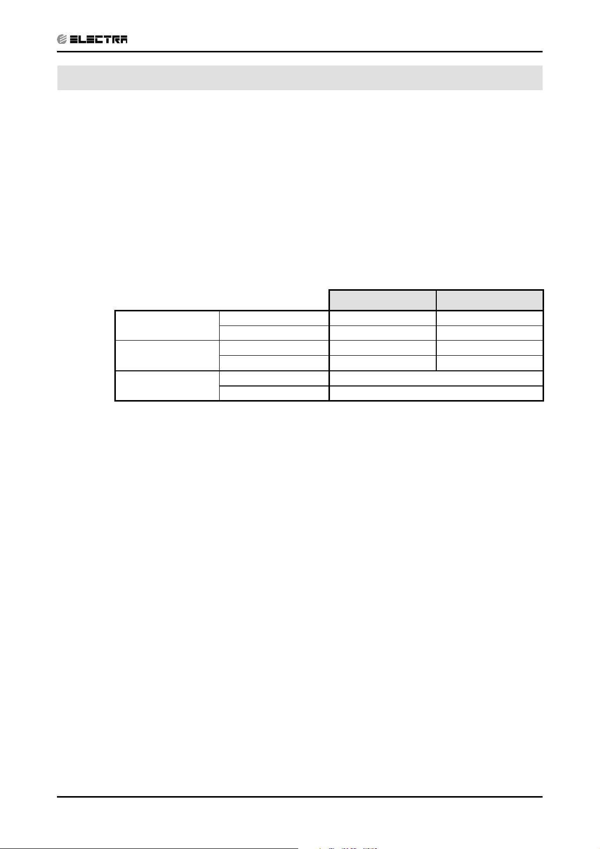
4. OUTLINE DIMENSIONS
CONTENT
4.1 Indoor Unit: DNG 18, 24, 30, 37, 44
OUTLINE DIMENSIONS
Model A B C D E F G H I J K L
DNG 18,24,30
DNG 37,44
790 653 749 758 797 256 195 702 599 684 162 242
854 715 816 822 861 297 235 770 663 749 193 282
Revision Y05-01Service Manual - DNG Series
4-1
Page 18
OUTLINE DIMENSIONS
CONTENT
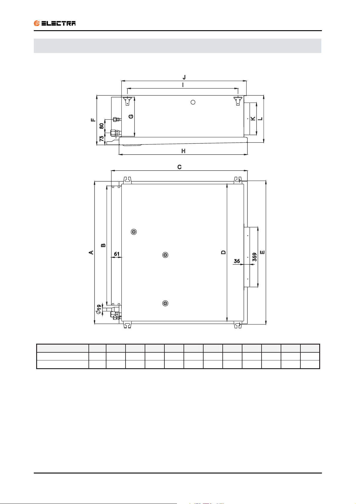
4.2 Outdoor Unit: GC 18
Outdoor Unit: OU7 24
4.3
4-2
Revision Y05-01 Service Manual - DNG Series
Page 19
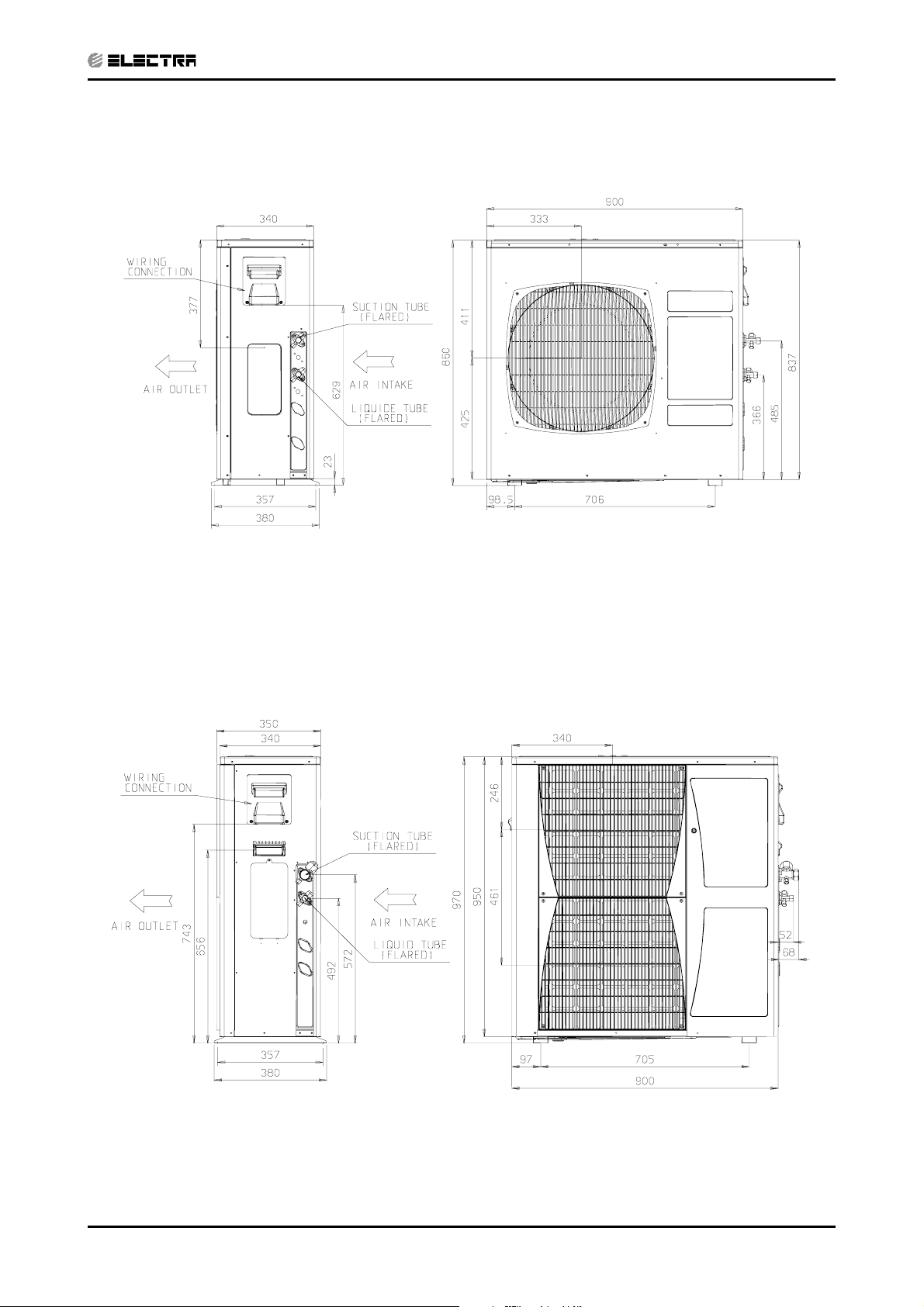
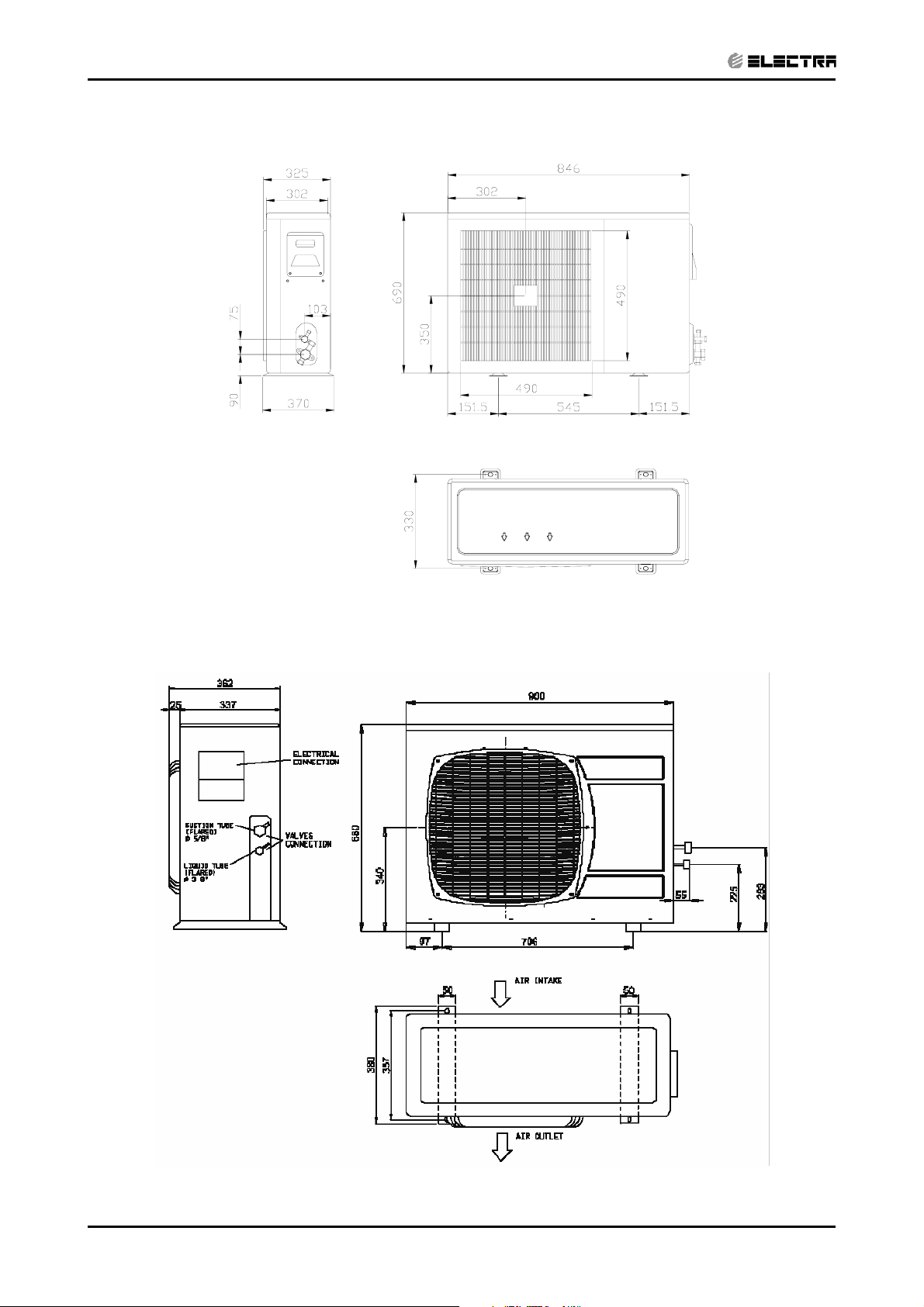
4.4 Outdoor Unit: OU8-33
CONTENT
OUTLINE DIMENSIONS
Outdoor Unit: OU10 36, 44
4.5
Revision Y05-01Service Manual - DNG Series
4-3
Page 20
PERFORMANCE DATA & PRESSURE CURVES
CONTENT
5. PERFORMANCE DATA & PRESSURE CURVES
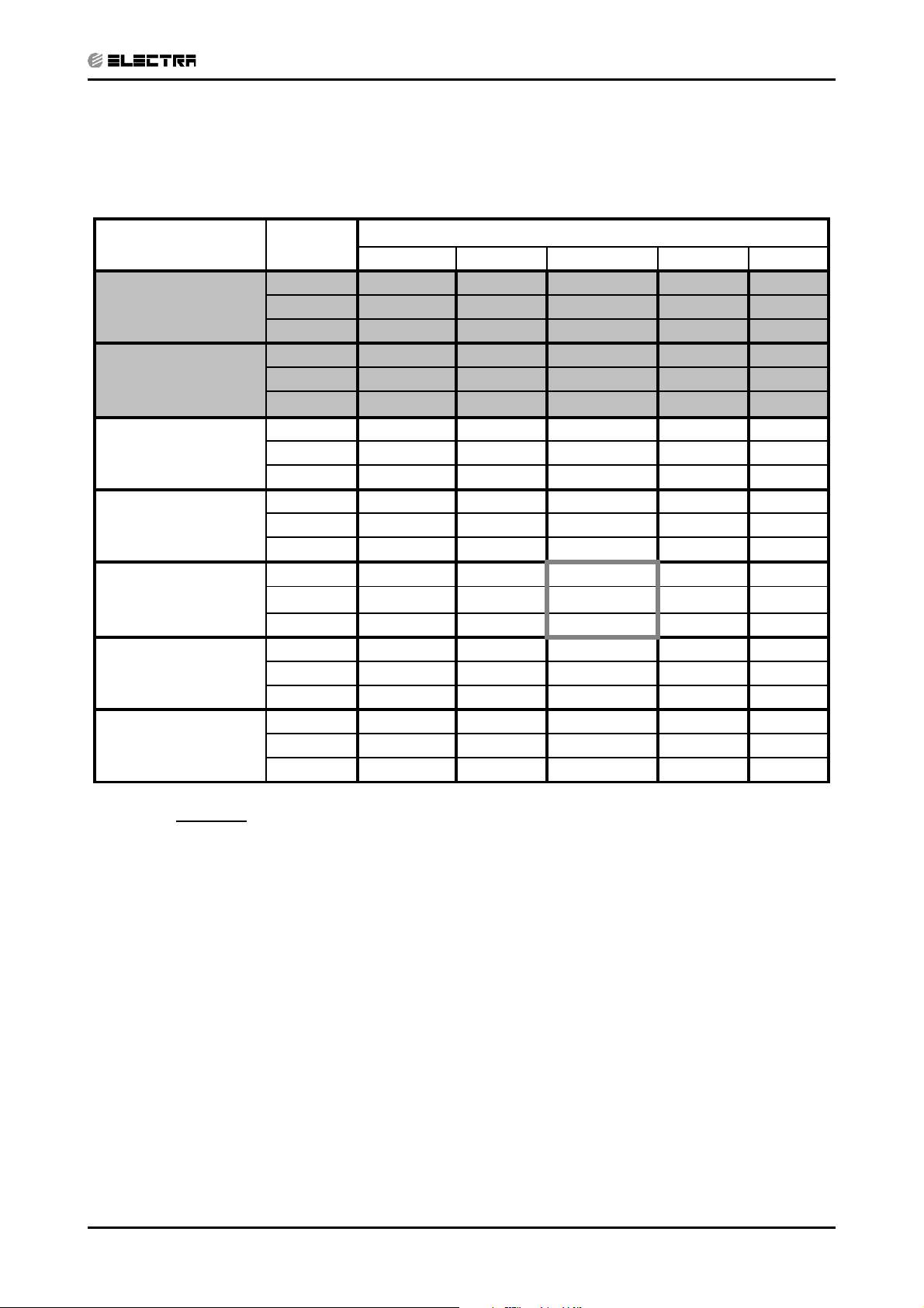
5.1 DNG 18, GC18 1PH / 3PH
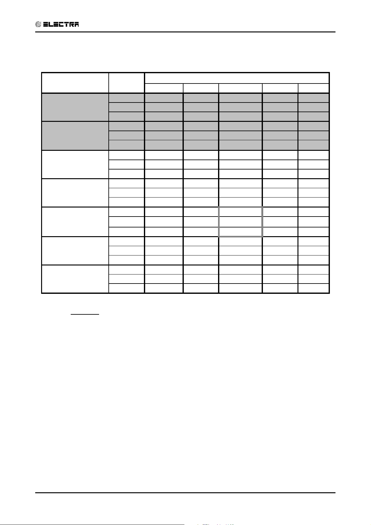
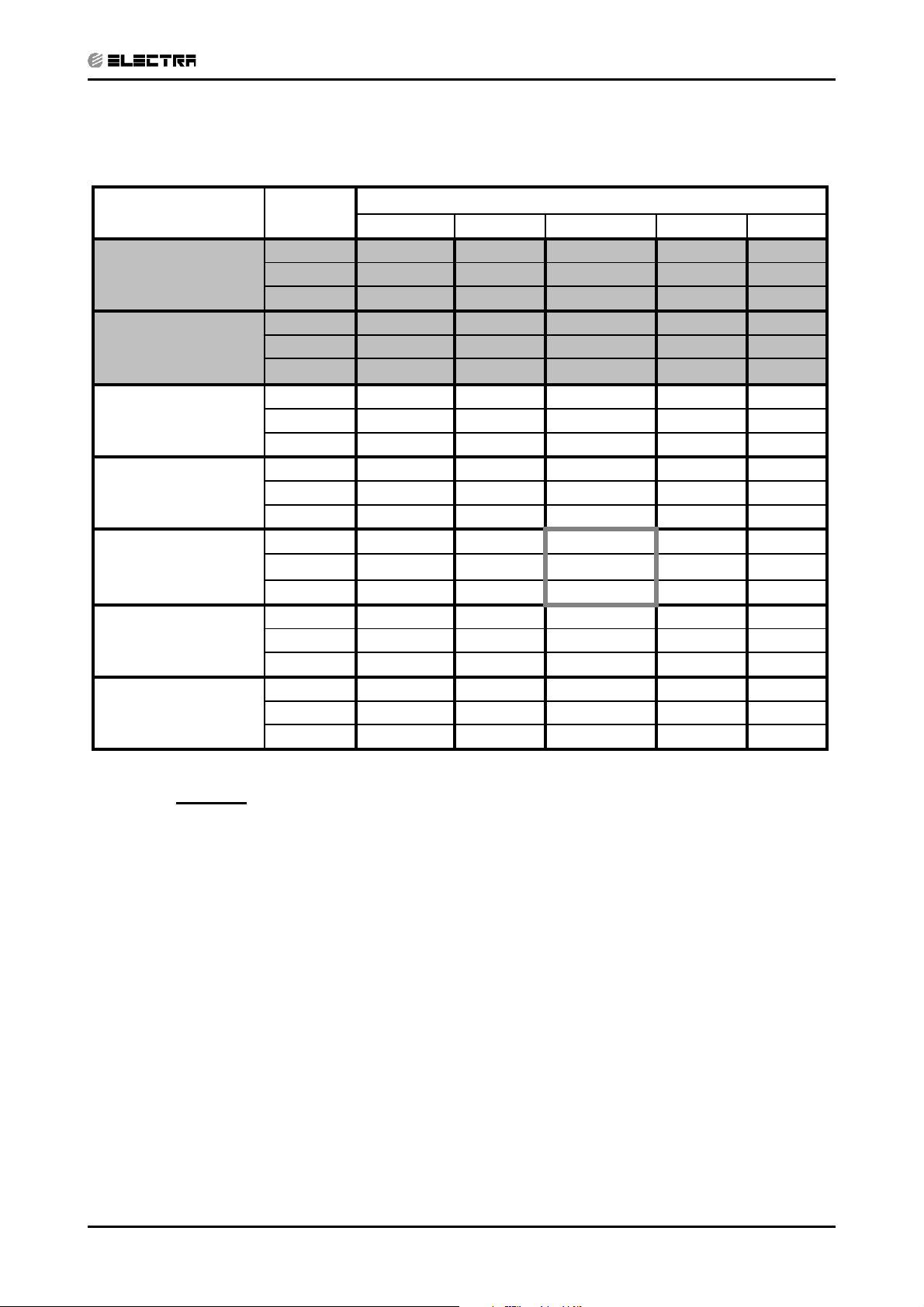
5.1.1 Cooling Capacity (kW)
Entering Air DB
OD Coil(
o
C)
15 SC
20 SC
25 SC
30 SC
35 SC
40 SC
46 SC
Data
TC
PL
TC
PL
TC
PL
TC
PL
TC
PL
TC
PL
TC
PL
Entering Air WB/DB ID Coil(oC)
15/21 17/24 19/27 21/29 23/32
5.71 6.05 6.33 6.61 6.83
3.77 4.00 4.21 4.12 4.19
1.28 1.28 1.28 1.29 1.29
5.66 5.99 6.27 6.55 6.78
4.03 4.28 4.53 4.40 4.49
1.38 1.39 1.40 1.40 1.41
5.43 5.82 6.16 6.44 6.66
3.67 3.93 4.15 4.08 4.18
1.49 1.50 1.52 1.53 1.53
5.10 5.49 5.94 6.16 6.38
3.48 3.76 4.06 3.98 4.14
1.61 1.63 1.65 1.67 1.67
4.70 5.10
3.28 3.57
1.74 1.77
5.60
3.90
1.80
5.88 6.10
3.85 4.01
1.81 1.82
4.26 4.65 5.15 5.43 5.66
3.05 3.35 3.69 3.63 3.81
1.88 1.91 1.94 1.96 1.98
3.70 4.09 4.59 4.87 5.10
2.77 3.07 3.46 3.39 3.55
2.06 2.10 2.13 2.16 2.18
LEGEND
TC – Total Cooling Capacity, kW
SC – Sensible Capacity, kW
PI – Power Input, kW
WB – Wet Bulb Temp., (oC)
DB – Dry Bulb Temp., (
ID – Indoor
OD – Outdoor
o
C)
Revision Y05-01Service Manual - DNG Series
5-1
Page 21
PERFORMANCE DATA & PRESSURE CURVES
CONTENT
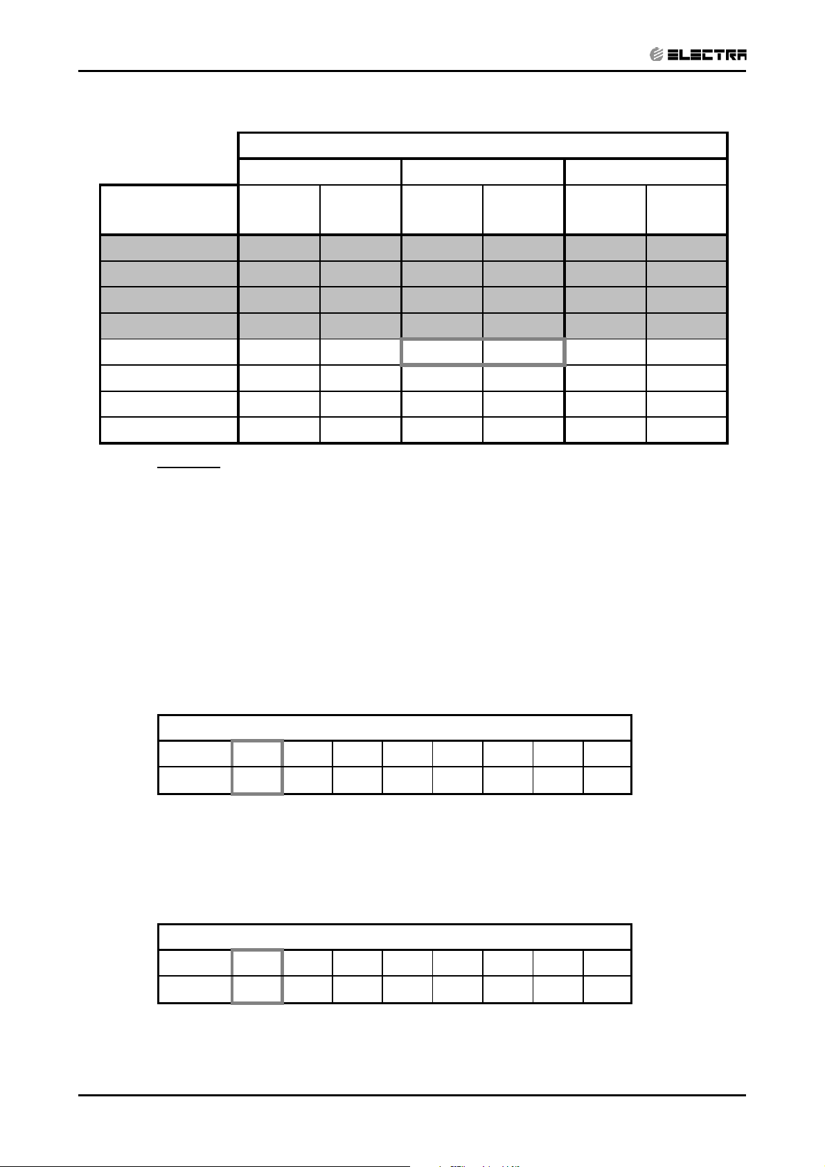
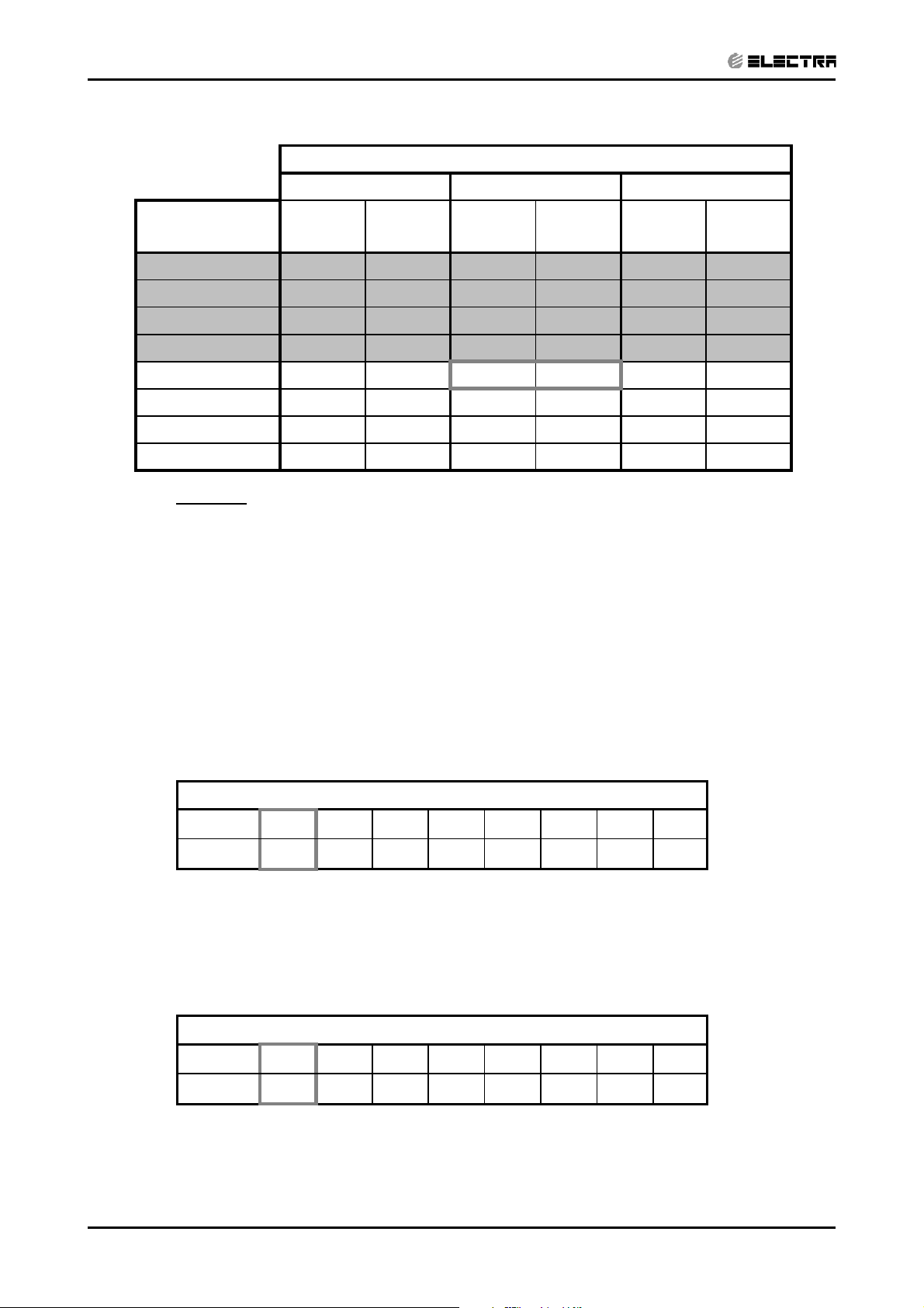
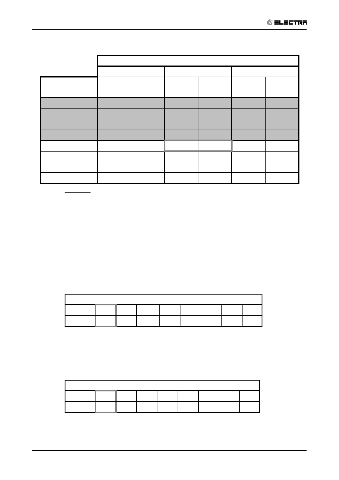
5.1.2 Heating
ENTERING AIR DB ID COIL(Oc)
15 20 25
ENTERING WB
o
OD COIL(
C)
-10 3.06 1.36 2.94 1.45 2.83 1.52
-7 3.29 1.39 3.18 1.47 3.06 1.55
-2 3.50 1.41 3.38 1.50 3.26 1.58
2 4.26 1.48 4.08 1.57 3.91 1.67
6 5.46 1.59
10 5.94 1.68 5.78 1.79 5.62 1.92
15 6.41 1.75 6.25 1.89 6.10 2.01
20 6.76 1.80 6.60 1.96 6.41 2.11
LEGEND
TH – Total Heating Capacity, kW
PI – Power Input, kW
WB – Wet Bulb Temp., (oC)
DB – Dry Bulb Temp., (oC)
ID – Indoor
OD – Outdoor
TH Pl TH Pl TH Pl
5.30 1.70
5.11 1.81
5.2 Capacity Correction Factor Due to Tubing Length
5.2.1 Cooling
TOTAL TUBING LENGTH (One Way)
3m
1.01
7.5m
10m 15m 20m 25m 30m 40m 50m
1
0.97 0.96 0.95 0.94 --- --- ---
* Minimum recommended tubing length between indoor and outdoor units is 3m.
5.2.2 Heating
TOTAL TUBING LENGTH (One Way)
3m
1.02
7.5m
10m 15m 20m 25m 30m 40m 50m
1
0.98 0.97 0.95 0.93 --- --- ---
* Minimum recommended tubing length between indoor and outdoor units is 3m.
5-2
Revision Y05-01 Service Manual - DNG Series
Page 22
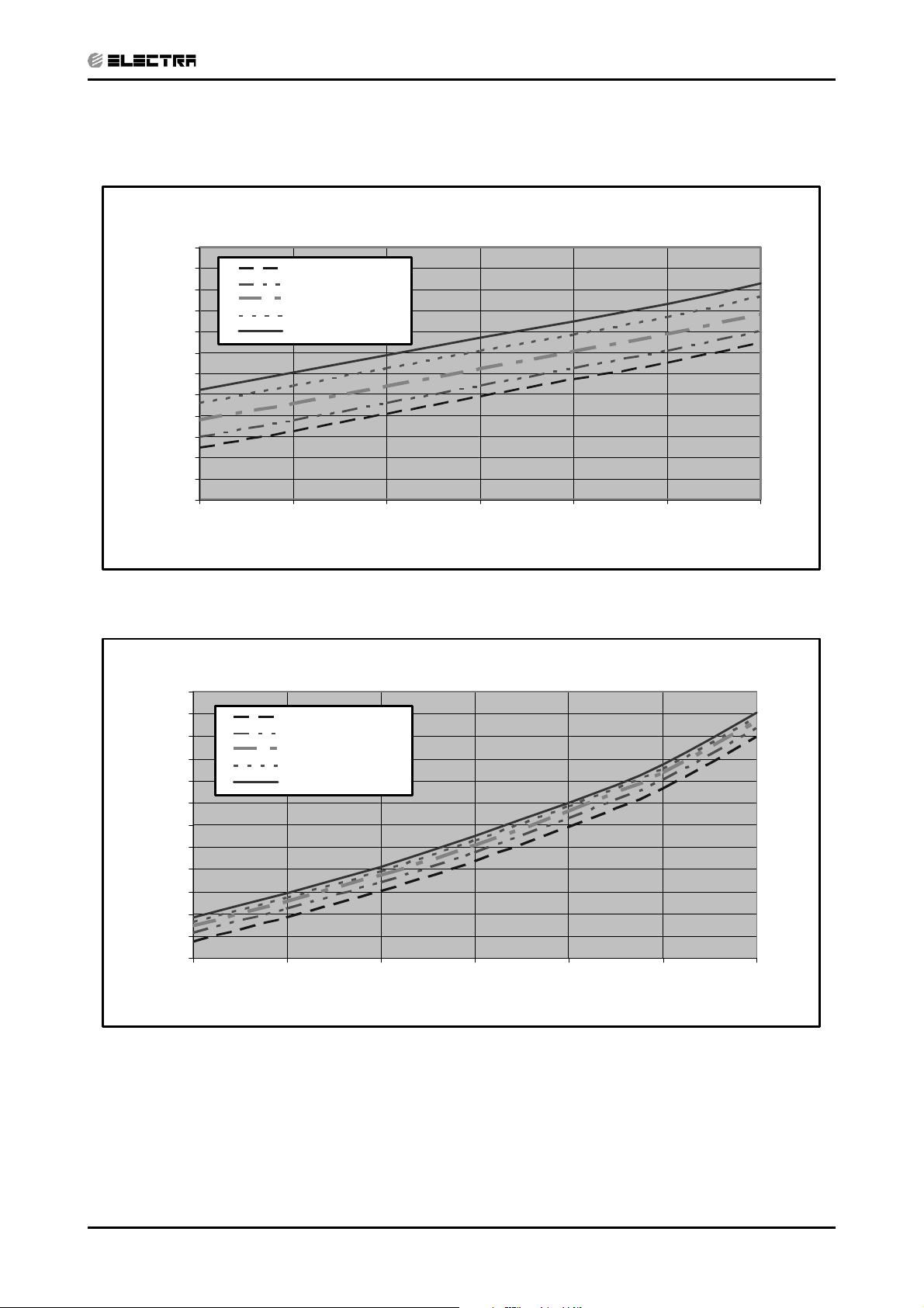
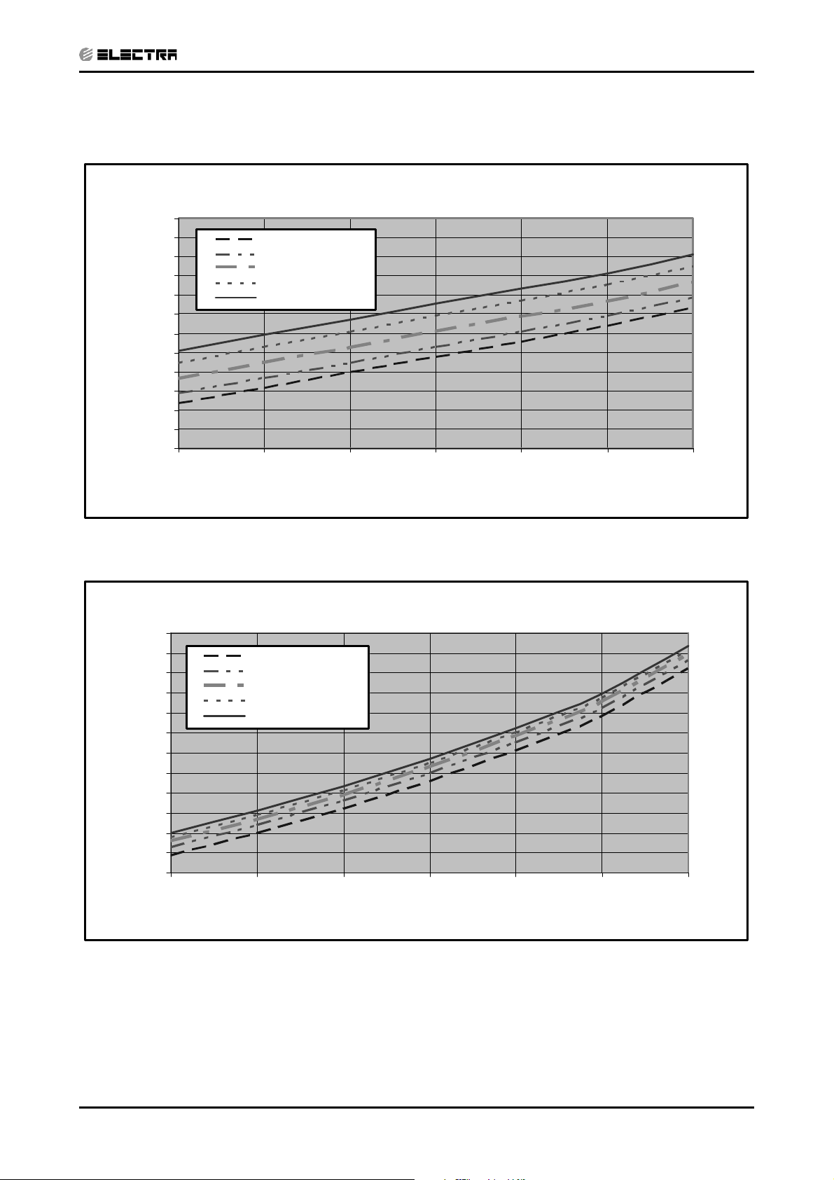
5.3 Pressure Curves
CONTENT
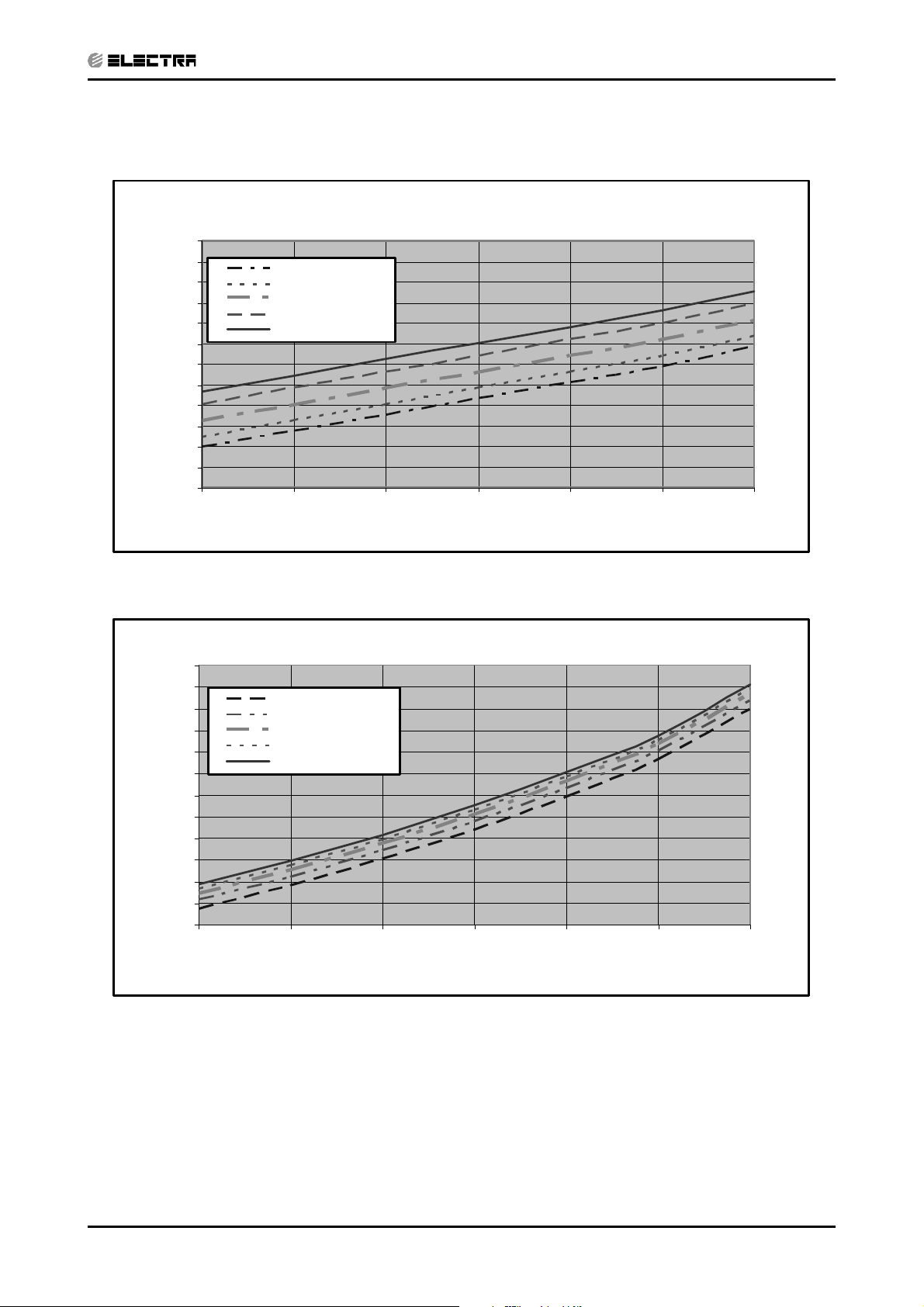
5.3.1 Cooling
Suction Pressure VS.Outdoor Temp
12.0
11.5
11.0
10.5
10.0
9.5
9.0
8.5
8.0
7.5
7.0
Suction Pressure (Bar[g])
6.5
6.0
15 20 25 30 35 40 46
21/15(DB/WB ºC)
24/17(DB/WB ºC)
27/19(DB/WB ºC)
29/21(DB/WB ºC)
32/23(DB/WB ºC)
PERFORMANCE DATA & PRESSURE CURVES
Outdoor Temp.(DB oC )
Discharge Pressure VS.Outdoor Temp
40
38
36
34
32
30
28
26
24
22
20
18
Discharge Pressure (Bar[g])
16
15 20 25 30 35 40 46
21/15(DB/WB ºC)
24/17(DB/WB ºC)
27/19(DB/WB ºC)
29/21(DB/WB ºC)
32/23(DB/WB ºC)
Outdoor Temp.(DB oC )
Revision Y05-01Service Manual - DNG Series
5-3
Page 23
PERFORMANCE DATA & PRESSURE CURVES
CONTENT
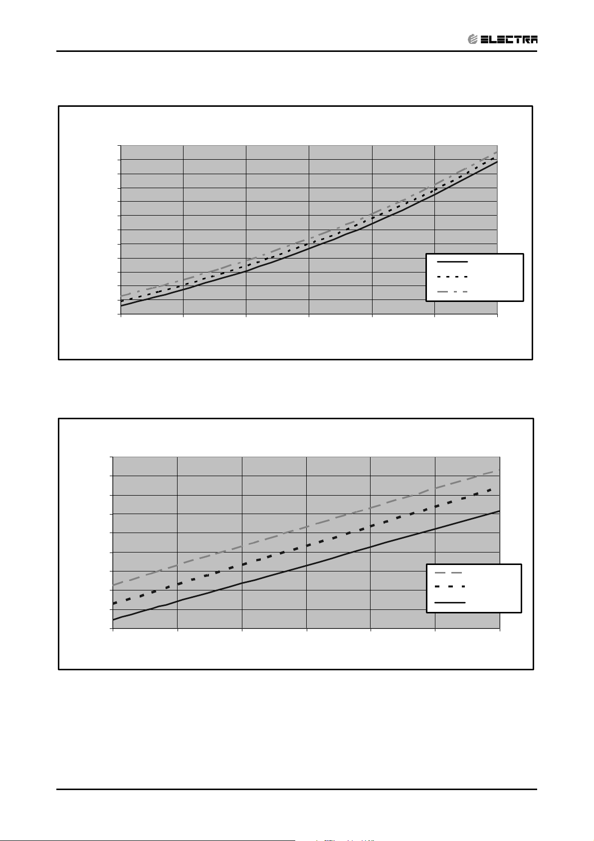
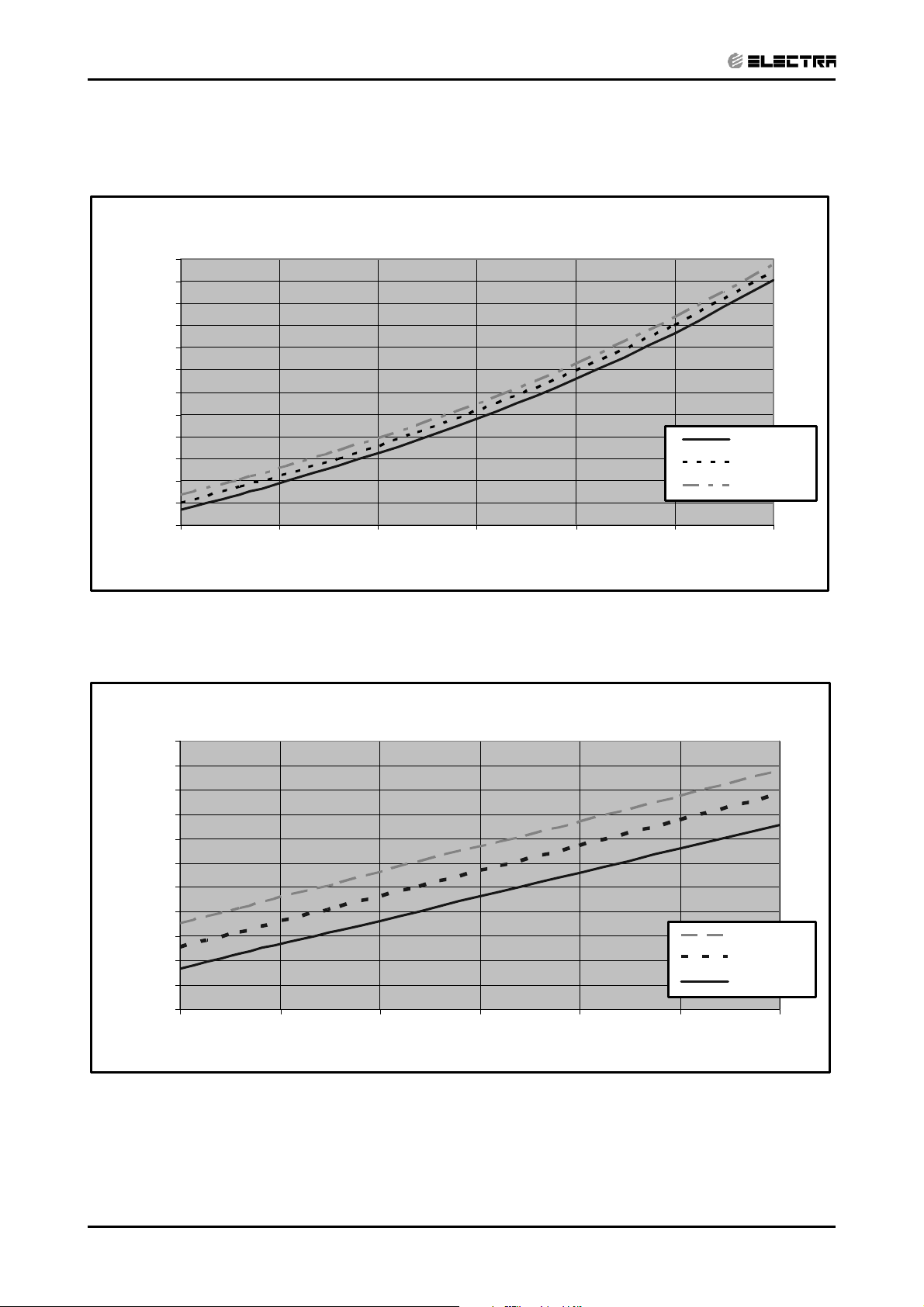
5.3.2 Heating
Suction Pressure VS.Outdoor Temp'
10.0
9.5
9.0
8.5
8.0
7.5
7.0
6.5
6.0
5.5
5.0
Suction Pressure(Bar[g])
4.5
4.0
-10 -5 0 5 10 15 20
15 DB (ºC)
20 DB (ºC)
25 DB (ºC)
Outdoor Temp.( WB oC )
Discharge Pressure VS.Outdoor Temp'
38
36
34
32
30
28
26
24
22
Discharge Pressure(Bar[g])
20
-10 -5 0 5 10 15 20
Outdoor Temp.( WB oC )
25 DB (ºC)
20 DB (ºC)
15 DB (ºC)
5-4
Revision Y05-01 Service Manual - DNG Series
Page 24
PERFORMANCE DATA & PRESSURE CURVES
CONTENT
5.4 DNG 24, OU7- 24 1PH / 3PH
5.4.1 Cooling Capacity (kW)
Entering Air DB
OD Coil(
o
C)
15 SC
20 SC
25 SC
30 SC
35 SC
40 SC
46 SC
Data
TC
PL
TC
PL
TC
PL
TC
PL
TC
PL
TC
PL
TC
PL
Entering Air WB/DB ID Coil(oC)
15/21 17/24 19/27 21/29 23/32
7.04 7.45 7.80 8.14 8.42
5.17 5.48 5.78 5.64 5.74
1.70 1.71 1.71 1.72 1.72
6.97 7.38 7.73 8.07 8.35
4.97 5.28 5.58 5.42 5.54
1.84 1.85 1.86 1.87 1.88
6.69 7.18 7.59 7.94 8.21
5.03 5.38 5.69 5.59 5.73
1.99 2.00 2.02 2.04 2.04
6.28 6.76 7.31 7.59 7.87
4.78 5.16 5.57 5.46 5.68
2.15 2.18 2.21 2.22 2.23
5.80 6.28
4.50 4.89
2.33 2.36
6.90
5.35
2.40
7.25 7.52
5.29 5.50
2.42 2.43
5.24 5.73 6.35 6.69 6.97
4.18 4.60 5.06 4.98 5.22
2.51 2.54 2.59 2.62 2.64
4.55 5.04 5.66 6.00 6.28
3.80 4.21 4.74 4.65 4.87
2.75 2.79 2.84 2.88 2.91
LEGEND
TC – Total Cooling Capacity, kW
SC – Sensible Capacity, kW
PI – Power Input, kW
WB – Wet Bulb Temp., (oC)
DB – Dry Bulb Temp., (
ID – Indoor
OD – Outdoor
o
C)
Revision Y05-01Service Manual - DNG Series
5-5
Page 25
PERFORMANCE DATA & PRESSURE CURVES
CONTENT
5.4.2 Heating
ENTERING AIR DB ID COIL(Oc)
15 20 25
ENTERING WB
OD COIL(
LEGEND
TH – Total Heating Capacity, kW
PI – Power Input, kW
WB – Wet Bulb Temp., (oC)
DB – Dry Bulb Temp., (oC)
ID – Indoor
OD – Outdoor
o
C)
-10 4.04 1.84 3.89 1.96 3.73 2.06
-7 4.35 1.89 4.20 1.99 4.04 2.10
-2 4.62 1.91 4.47 2.02 4.31 2.14
2 5.62 2.00 5.39 2.13 5.16 2.25
67.212.15
10 7.84 2.27 7.63 2.43 7.42 2.59
15 8.47 2.37 8.26 2.55 8.05 2.71
20 8.93 2.44 8.72 2.65 8.47 2.85
TH Pl TH Pl TH Pl
7.00 2.30
6.76 2.44
5.5 Capacity Correction Factor Due to Tubing Length
5.5.1 Cooling
TOTAL TUBING LENGTH (One Way)
3m
1.01
7.5m
10m 15m 20m 25m 30m 40m 50m
1
0.98 0.97 0.96 0.95 0.94 0.93 0.9
* Minimum recommended tubing length between indoor and outdoor units is 3m.
5.5.2 Heating
TOTAL TUBING LENGTH (One Way)
3m
1.02
7.5m
10m 15m 20m 25m 30m 40m 50m
1
0.99 0.99 0.98 0.97 0.97 0.96 0.95
* Minimum recommended tubing length between indoor and outdoor units is 3m.
5-6
Revision Y05-01 Service Manual - DNG Series
Page 26
5.6 Pressure Curves
CONTENT
5.6.1 Cooling
Suction Pressure VS.Outdoor Temp
12.0
11.5
11.0
10.5
10.0
9.5
9.0
8.5
8.0
7.5
7.0
Suction Pressure (Bar[g])
6.5
6.0
15 20 25 30 35 40 46
21/15(DB/WB ºC)
24/17(DB/WB ºC)
27/19(DB/WB ºC)
29/21(DB/WB ºC)
32/23(DB/WB ºC)
PERFORMANCE DATA & PRESSURE CURVES
Outdoor Temp.(DB oC )
Discharge Pressure VS.Outdoor Temp
40
38
36
34
32
30
28
26
24
22
20
18
Discharge Pressure (Bar[g])
16
15 20 25 30 35 40 46
21/15(DB/WB ºC)
24/17(DB/WB ºC)
27/19(DB/WB ºC)
29/21(DB/WB ºC)
32/23(DB/WB ºC)
Outdoor Temp.(DB oC )
Revision Y05-01Service Manual - DNG Series
5-7
Page 27
PERFORMANCE DATA & PRESSURE CURVES
CONTENT
5.6.2 Heating
Suction Pressure VS.Outdoor Temp
10.0
9.5
9.0
8.5
8.0
7.5
7.0
6.5
6.0
5.5
5.0
Suction Pressure(Bar[g])
4.5
4.0
-10 -5 0 5 10 15 20
Outdoor Temp.( WB oC )
15 DB (ºC)
20 DB (ºC)
25 DB (ºC)
Discharge Pressure VS.Outdoor Temp
40
38
36
34
32
30
28
26
24
22
20
Discharge Pressure(Bar[g])
18
-10 -5 0 5 10 15 20
Outdoor Temp.( WB oC )
25 DB (ºC)
20 DB (ºC)
15 DB (ºC)
5-8
Revision Y05-01 Service Manual - DNG Series
Page 28
PERFORMANCE DATA & PRESSURE CURVES
CONTENT
5.7 DNG 30, OU8- 30 1PH / 3PH
5.7.1 Cooling Capacity (kW)
Entering Air DB
OD Coil(
o
C)
15 SC
20 SC
25 SC
30 SC
35 SC
40 SC
46 SC
Data
TC
PL
TC
PL
TC
PL
TC
PL
TC
PL
TC
PL
TC
PL
Entering Air WB/DB ID Coil(oC)
15/21 17/24 19/27 21/29 23/32
8.67 9.18 9.61 10.03 10.37
6.27 6.65 7.01 6.85 6.96
2.13 2.13 2.14 2.15 2.15
8.59 9.10 9.52 9.95 10.29
6.12 6.50 6.87 6.67 6.82
2.30 2.31 2.33 2.34 2.35
8.25 8.84 9.35 9.78 10.12
6.10 6.53 6.91 6.78 6.96
2.48 2.51 2.53 2.55 2.55
7.74 8.33 9.01 9.35 9.69
5.79 6.25 6.76 6.62 6.89
2.69 2.72 2.76 2.78 2.79
7.14 7.74
5.46 5.93
2.91 2.95
8.50
6.49
3.00
8.93 9.27
6.41 6.67
3.02 3.04
6.46 7.06 7.82 8.25 8.59
5.07 5.58 6.13 6.04 6.33
3.13 3.18 3.24 3.27 3.29
5.61 6.21 6.97 7.40 7.74
4.61 5.11 5.75 5.64 5.91
3.44 3.49 3.55 3.60 3.64
LEGEND
TC – Total Cooling Capacity, kW
SC – Sensible Capacity, kW
PI – Power Input, kW
WB – Wet Bulb Temp., (
DB – Dry Bulb Temp., (
ID – Indoor
OD – Outdoor
o
C)
o
C)
Revision Y05-01Service Manual - DNG Series
5-9
Page 29
PERFORMANCE DATA & PRESSURE CURVES
CONTENT
5.7.2 Heating
ENTERING AIR DB ID COIL(Oc)
15 20 25
ENTERING WB
o
OD COIL(
C)
-10 5.20 2.24 5.00 2.39 4.80 2.51
-7 5.59 2.30 5.40 2.42 5.20 2.55
-2 5.94 2.32 5.74 2.46 5.54 2.60
2 7.23 2.44 6.93 2.59 6.63 2.74
6 9.27 2.62
10 10.08 2.76 9.81 2.95 9.54 3.16
15 10.89 2.88 10.62 3.11 10.35 3.30
20 11.48 2.97 11.21 3.22 10.89 3.47
LEGEND
TH – Total Heating Capacity, kW
PI – Power Input, kW
WB – Wet Bulb Temp., (oC)
DB – Dry Bulb Temp., (oC)
ID – Indoor
OD – Outdoor
TH Pl TH Pl TH Pl
9.00 2.80
8.69 2.97
5.8 Capacity Correction Factor Due to Tubing Length
5.8.1 Cooling
TOTAL TUBING LENGTH (One Way)
3m
1.01
7.5m
10m 15m 20m 25m 30m 40m 50m
1
0.98 0.97 0.96 0.95 0.94 0.93 0.9
* Minimum recommended tubing length between indoor and outdoor units is 3m.
5.8.2 Heating
TOTAL TUBING LENGTH (One Way)
3m
1.02
7.5m
10m 15m 20m 25m 30m 40m 50m
1
0.99 0.99 0.98 0.97 0.97 0.96 0.95
* Minimum recommended tubing length between indoor and outdoor units is 3m.
5-10
Revision Y05-01 Service Manual - DNG Series
Page 30
5.9 Pressure Curves
CONTENT
5.9.1 Cooling
Suction Pressure VS.Outdoor Temp'
12.0
11.5
11.0
10.5
10.0
9.5
9.0
8.5
8.0
7.5
7.0
Suction Pressure (Bar[g])
6.5
6.0
15 20 25 30 35 40 46
21/15(DB/WB ºC)
24/17(DB/WB ºC)
27/19(DB/WB ºC)
29/21(DB/WB ºC)
32/23(DB/WB ºC)
PERFORMANCE DATA & PRESSURE CURVES
Outdoor Temp.(DB oC )
Discharge Pressure VS.Outdoor Temp'
40
38
36
34
32
30
28
26
24
22
20
18
Discharge Pressure (Bar[g])
16
15 20 25 30 35 40 46
21/15(DB/WB ºC)
24/17(DB/WB ºC)
27/19(DB/WB ºC)
29/21(DB/WB ºC)
32/23(DB/WB ºC)
Outdoor Temp.(DB oC )
Revision Y05-01Service Manual - DNG Series
5-11
Page 31

PERFORMANCE DATA & PRESSURE CURVES
CONTENT
5.9.2 Heating
Suction Pressure VS.Outdoor Temp'
10.0
9.5
9.0
8.5
8.0
7.5
7.0
6.5
6.0
5.5
5.0
Suction Pressure(Bar[g])
4.5
4.0
-10 -5 0 5 10 15 20
15 DB (ºC)
20 DB (ºC)
25 DB (ºC)
Outdoor Temp.( WB oC )
Discharge Pressure VS.Outdoor Temp'
36
34
32
30
28
26
24
22
20
Discharge Pressure(Bar[g])
18
-10 -5 0 5 10 15 20
25 DB (ºC)
20 DB (ºC)
15 DB (ºC)
5-12
Outdoor Temp.( WB oC )
Revision Y05-01 Service Manual - DNG Series
Page 32

5.10 DNG 37, OU10- 36 1PH
CONTENT
5.10.1 Cooling Capacity (kW)
PERFORMANCE DATA & PRESSURE CURVES
Entering Air DB
OD Coil(
o
C)
15 SC
20 SC
25 SC
30 SC
35 SC
40 SC
46 SC
Data
TC
PL
TC
PL
TC
PL
TC
PL
TC
PL
TC
PL
TC
PL
Entering Air WB/DB ID Coil(oC)
15/21 17/24 19/27 21/29 23/32
10.81 11.45 11.98 12.51 12.93
7.92 8.40 8.85 8.65 8.80
2.70 2.70 2.71 2.72 2.73
10.71 11.34 11.87 12.40 12.83
7.63 8.11 8.57 8.32 8.50
2.91 2.93 2.95 2.96 2.97
10.28 11.02 11.66 12.19 12.61
7.70 8.25 8.72 8.57 8.79
3.15 3.17 3.20 3.23 3.23
9.65 10.39 11.24 11.66 12.08
7.32 7.90 8.53 8.36 8.70
3.40 3.45 3.49 3.52 3.53
8.90 9.65
6.89 7.50
3.68 3.74
10.60
8.19
3.80
11.13 11.55
8.10 8.43
3.83 3.85
8.06 8.80 9.75 10.28 10.71
6.40 7.05 7.75 7.63 8.00
3.97 4.03 4.10 4.14 4.17
7.00 7.74 8.69 9.22 9.65
5.82 6.45 7.27 7.13 7.47
4.35 4.42 4.50 4.56 4.61
LEGEND
TC – Total Cooling Capacity, kW
SC – Sensible Capacity, kW
PI – Power Input, kW
WB – Wet Bulb Temp., (
DB – Dry Bulb Temp., (
ID – Indoor
OD – Outdoor
o
C)
o
C)
Revision Y05-01Service Manual - DNG Series
5-13
Page 33

PERFORMANCE DATA & PRESSURE CURVES
CONTENT
5.10.2 Heating
ENTERING AIR DB ID COIL(Oc)
15 20 25
ENTERING WB
OD COIL(
o
C)
-10 6.47 2.94 6.22 3.13 5.98 3.28
-7 6.96 3.01 6.71 3.17 6.47 3.35
-2 7.39 3.05 7.15 3.23 6.90 3.41
2 8.99 3.19 8.62 3.39 8.25 3.60
6 11.54 3.43
10 12.54 3.62 12.21 3.87 11.87 4.14
15 13.55 3.78 13.22 4.07 12.88 4.33
20 14.28 3.89 13.94 4.22 13.55 4.55
LEGEND
TH – Total Heating Capacity, kW
PI – Power Input, kW
WB – Wet Bulb Temp., (oC)
DB – Dry Bulb Temp., (oC)
ID – Indoor
OD – Outdoor
TH Pl TH Pl TH Pl
11.20 3.67
10.81 3.90
5.11 Capacity Correction Factor Due to Tubing Length
5.11.1 Cooling
TOTAL TUBING LENGTH (One Way)
3m
1.02
7.5m
10m 15m 20m 25m 30m 40m 50m
1
0.99 0.98 0.98 0.97 0.96 0.95 0.92
* Minimum recommended tubing length between indoor and outdoor units is 3m.
5.11.2 Heating
TOTAL TUBING LENGTH (One Way)
3m
1.03
7.5m
10m 15m 20m 25m 30m 40m 50m
1
0.99 0.99 0.98 0.98 0.97 0.96 0.95
* Minimum recommended tubing length between indoor and outdoor units is 3m.
5-14
Revision Y05-01 Service Manual - DNG Series
Page 34

5.12 DNG 37, OU10- 36 3PH
CONTENT
5.12.1 Cooling Capacity (kW)
PERFORMANCE DATA & PRESSURE CURVES
Entering Air DB
OD Coil(
o
C)
15 SC
20 SC
25 SC
30 SC
35 SC
40 SC
46 SC
Data
TC
PL
TC
PL
TC
PL
TC
PL
TC
PL
TC
PL
TC
PL
Entering Air WB/DB ID Coil(oC)
15/21 17/24 19/27 21/29 23/32
10.61 11.23 11.75 12.27 12.69
7.77 8.24 8.68 8.49 8.63
2.61 2.61 2.61 2.63 2.64
10.50 11.13 11.65 12.17 12.58
7.49 7.96 8.41 8.16 8.34
2.81 2.83 2.84 2.86 2.87
10.09 10.82 11.44 11.96 12.38
7.56 8.09 8.56 8.41 8.62
3.04 3.06 3.09 3.12 3.12
9.46 10.19 11.02 11.44 11.86
7.18 7.75 8.37 8.21 8.54
3.29 3.33 3.37 3.40 3.41
8.74 9.46
6.76 7.35
3.56 3.61
10.40
8.04
3.67
10.92 11.34
7.95 8.27
3.70 3.71
7.90 8.63 9.57 10.09 10.50
6.28 6.91 7.60 7.49 7.85
3.83 3.89 3.96 4.00 4.03
6.86 7.59 8.53 9.05 9.46
5.71 6.33 7.13 6.99 7.33
4.20 4.27 4.35 4.40 4.45
LEGEND
TC – Total Cooling Capacity, kW
SC – Sensible Capacity, kW
PI – Power Input, kW
WB – Wet Bulb Temp., (
DB – Dry Bulb Temp., (oC)
ID – Indoor
OD – Outdoor
o
C)
Revision Y05-01Service Manual - DNG Series
5-15
Page 35

PERFORMANCE DATA & PRESSURE CURVES
CONTENT
5.12.2 Heating
ENTERING AIR DB ID COIL(Oc)
15 20 25
ENTERING WB
OD COIL(
o
C)
-10 6.41 2.86 6.17 3.05 5.92 3.20
-7 6.90 2.94 6.65 3.10 6.41 3.26
-2 7.33 2.97 7.08 3.15 6.84 3.33
2 8.91 3.11 8.55 3.31 8.18 3.51
6 11.43 3.35
10 12.43 3.53 12.10 3.78 11.77 4.04
15 13.43 3.69 13.10 3.97 12.77 4.22
20 14.15 3.79 13.82 4.12 13.43 4.44
LEGEND
TH – Total Heating Capacity, kW
PI – Power Input, kW
WB – Wet Bulb Temp., (oC)
DB – Dry Bulb Temp., (oC)
ID – Indoor
OD – Outdoor
TH Pl TH Pl TH Pl
11.10 3.58
10.71 3.80
5.13 Capacity Correction Factor Due to Tubing Length
5.13.1 Cooling
TOTAL TUBING LENGTH (One Way)
3m
1.02
7.5m
10m 15m 20m 25m 30m 40m 50m
1
0.99 0.98 0.98 0.97 0.96 0.95 0.92
* Minimum recommended tubing length between indoor and outdoor units is 3m.
5.13.2 Heating
TOTAL TUBING LENGTH (One Way)
3m
1.03
7.5m
10m 15m 20m 25m 30m 40m 50m
1
0.99 0.99 0.98 0.98 0.97 0.96 0.95
* Minimum recommended tubing length between indoor and outdoor units is 3m.
5-16
Revision Y05-01 Service Manual - DNG Series
Page 36

PERFORMANCE DATA & PRESSURE CURVES
CONTENT
5.14 Pressure Curves – DNG 37 1PH/3PH
5.14.1 Cooling
Suction Pressure VS.Outdoor Temp
12.0
11.5
11.0
10.5
10.0
9.5
9.0
8.5
8.0
7.5
7.0
Suction Pressure (Bar[g])
6.5
6.0
15 20 25 30 35 40 46
21/15(DB/WB ºC)
24/17(DB/WB ºC)
27/19(DB/WB ºC)
29/21(DB/WB ºC)
32/23(DB/WB ºC)
Outdoor Temp.(DB oC )
Discharge Pressure VS.Outdoor Temp
40
38
36
34
32
30
28
26
24
22
20
18
Discharge Pressure (Bar[g])
16
15 20 25 30 35 40 46
21/15(DB/WB ºC)
24/17(DB/WB ºC)
27/19(DB/WB ºC)
29/21(DB/WB ºC)
32/23(DB/WB ºC)
Outdoor Temp.(DB oC )
Revision Y05-01Service Manual - DNG Series
5-17
Page 37

PERFORMANCE DATA & PRESSURE CURVES
CONTENT
5.14.2 Heating
Suction Pressure VS.Outdoor Temp
10.0
9.5
9.0
8.5
8.0
7.5
7.0
6.5
6.0
5.5
5.0
Suction Pressure(Bar[g])
4.5
4.0
-10 -5 0 5 10 15 20
Outdoor Temp.( WB oC )
15 DB (ºC)
20 DB (ºC)
25 DB (ºC)
Discharge Pressure VS.Outdoor Temp
38
36
34
32
30
28
26
24
22
Discharge Pressure(Bar[g])
20
-10 -5 0 5 10 15 20
Outdoor Temp.( WB oC )
25 DB (ºC)
20 DB (ºC)
15 DB (ºC)
5-18
Revision Y05-01 Service Manual - DNG Series
Page 38

5.15 DNG 44, OU10- 44 3PH
CONTENT
5.15.1 Cooling Capacity (kW)
PERFORMANCE DATA & PRESSURE CURVES
Entering Air DB
o
OD Coil(
C)
15 SC
20 SC
25 SC
30 SC
35 SC
40 SC
46 SC
Data
TC
PL
TC
PL
TC
PL
TC
PL
TC
PL
TC
PL
TC
PL
Entering Air WB/DB ID Coil(oC)
15/21 17/24 19/27 21/29 23/32
12.65 13.39 14.01 14.63 15.13
8.93 9.47 9.98 9.75 9.92
3.27 3.27 3.28 3.29 3.30
12.52 13.27 13.89 14.51 15.00
8.93 9.49 10.03 9.73 9.95
3.53 3.55 3.57 3.59 3.60
12.03 12.90 13.64 14.26 14.76
8.69 9.30 9.84 9.66 9.91
3.81 3.84 3.88 3.91 3.91
11.28 12.15 13.14 13.64 14.14
8.25 8.91 9.62 9.43 9.81
4.12 4.17 4.23 4.26 4.27
10.42 11.28
7.77 8.45
4.46 4.53
12.40
9.24
4.60
13.02 13.52
9.13 9.50
4.64 4.66
9.42 10.29 11.41 12.03 12.52
7.22 7.94 8.74 8.60 9.02
4.80 4.88 4.96 5.01 5.05
8.18 9.05 10.17 10.79 11.28
6.56 7.27 8.19 8.04 8.42
5.27 5.35 5.45 5.52 5.58
LEGEND
TC – Total Cooling Capacity, kW
SC – Sensible Capacity, kW
PI – Power Input, kW
WB – Wet Bulb Temp., (oC)
DB – Dry Bulb Temp., (oC)
ID – Indoor
OD – Outdoor
Revision Y05-01Service Manual - DNG Series
5-19
Page 39

PERFORMANCE DATA & PRESSURE CURVES
CONTENT
5.15.2 Heating
ENTERING AIR DB ID COIL(Oc)
15 20 25
ENTERING WB
o
OD COIL(
C)
-10 7.97 3.64 7.67 3.88 7.36 4.07
-7 8.58 3.73 8.27 3.94 7.97 4.15
-2 9.11 3.78 8.80 4.00 8.50 4.23
2 11.08 3.96 10.63 4.21 10.17 4.46
6 14.21 4.25
10 15.46 4.49 15.04 4.80 14.63 5.13
15 16.70 4.69 16.28 5.05 15.87 5.37
20 17.60 4.82 17.18 5.23 16.70 5.64
LEGEND
TH – Total Heating Capacity, kW
PI – Power Input, kW
WB – Wet Bulb Temp., (oC)
DB – Dry Bulb Temp., (oC)
ID – Indoor
OD – Outdoor
TH Pl TH Pl TH Pl
13.80 4.55
13.32 4.83
5.16 Capacity Correction Factor Due to Tubing Length
5.16.1 Cooling
TOTAL TUBING LENGTH (One Way)
3m
1.02
7.5m
10m 15m 20m 25m 30m 40m 50m
1
0.99 0.98 0.98 0.97 0.96 0.95 0.92
* Minimum recommended tubing length between indoor and outdoor units is 3m.
5.16.2 Heating
TOTAL TUBING LENGTH(One Way)
3m
1.03
7.5m
10m 15m 20m 25m 30m 40m 50m
1
0.99 0.99 0.98 0.98 0.97 0.96 0.95
* Minimum recommended tubing length between indoor and outdoor units is 3m.
5-20
Revision Y05-01 Service Manual - DNG Series
Page 40

5.17 Pressure Curves
CONTENT
5.17.1 Cooling
Suction Pressure VS.Outdoor Temp
11.0
PERFORMANCE DATA & PRESSURE CURVES
10.5
10.0
9.5
9.0
8.5
8.0
7.5
7.0
Suction Pressure (Bar[g])
6.5
6.0
15 20 25 30 35 40 46
21/15(DB/WB ºC)
24/17(DB/WB ºC)
27/19(DB/WB ºC)
29/21(DB/WB ºC)
32/23(DB/WB ºC)
Outdoor Temp.(DB oC )
Discharge Pressure VS.Outdoor Temp
40
38
36
34
32
30
28
26
24
22
20
18
Discharge Pressure (Bar[g])
16
15 20 25 30 35 40 46
21/15(DB/WB ºC)
24/17(DB/WB ºC)
27/19(DB/WB ºC)
29/21(DB/WB ºC)
32/23(DB/WB ºC)
Outdoor Temp.(DB oC )
Revision Y05-01Service Manual - DNG Series
5-21
Page 41

PERFORMANCE DATA & PRESSURE CURVES
CONTENT
5.17.2 Heating
Suction Pressure VS.Outdoor Temp
10.0
9.5
9.0
8.5
8.0
7.5
7.0
6.5
6.0
5.5
5.0
Suction Pressure(Bar[g])
4.5
4.0
-10-5 0 5 101520
15 DB (ºC)
20 DB (ºC)
25 DB (ºC)
Outdoor Temp.( WB oC )
Discharge Pressure VS.Outdoor Temp
40
38
36
34
32
30
28
26
24
22
Discharge Pressure(Bar[g])
20
-10 -5 0 5 10 15 20
25 DB (ºC)
20 DB (ºC)
15 DB (ºC)
5-22
Outdoor Temp.( WB oC )
Revision Y05-01 Service Manual - DNG Series
Page 42

6. AIRFLOW CURVES
CONTENT
6.1 Model: DNG 18
Low Speed Medium Speed High Speed Super Speed
AIRFLOW CURVES
Operating range
6.2 Model: DNG 24
Low Speed Medium Speed High Speed Super Speed
Operating range
Revision Y05-01Service Manual - DNG Series
6-1
Page 43

AIRFLOW CURVES
CONTENT
6.3 Model: DNG 30
Low Speed Medium Speed High Speed Super Speed
Operating range
6.4 Model: DNG 37
Low Speed Medium Speed High Speed Super Speed
Operating range
6-2
Revision Y05-01 Service Manual - DNG Series
Page 44

6.5 Model: DNG 44
CONTENT
Low Speed Medium Speed High Speed
AIRFLOW CURVES
Operating range
6.6 DNG UNITS RANGE AIR FLOW CORRECTION FACTORS
* Permissible Air flow Rate - according to model Air Flow Curves
(at nominal rating conditions).
60% 70% 80% 90% 100%
0.88 0.91 0.94 0.97 1
Cooling
Heating
TC
SC 0.78 0.84 0.89 0.95 1
PI 0.95 0.97 0.98 0.99 1
PI 0.90 0.92 0.95 0.97 1
TC 1.07 1.05 1.03 1.02 1
Air Flow Rate [% of nominal]
Revision Y05-01Service Manual - DNG Series
6-3
Page 45

SOUND LEVEL CHARACTERISTICS
CONTENT
7. SOUND LEVEL CHARACTERISTICS
7.1 Sound Pressure Level
Figure 1. Wall Mounted Figure 2. Floor Mounted
Figure 3. Ducted Figure 4. Cassette
7.2 Soud Pressure Level Spectrum (Measured as Figure 3)
DNG 18 DNG 24
NC-70
NC-60
NC-50
NC-40
NC-30
OCTAVE BAND SOUND PRESSURE LEVEL, dB re 0.002 MICRO BAR
APPROXIMATE
THRESHOLD OF
HEARING FOR
CONTINUOUS
NOISE
NC-20
OCTAVE BAND SOUND PRESSURE LEVEL, dB re 0.002 MICRO BAR
APPROXIMATE
THRESHOLD OF
HEARING FOR
CONTINUOUS
NOISE
NC-70
NC-60
NC-50
NC-40
NC-30
NC-20
BAND CENTER FREQUENCIES, Hz
FAN SPEED LINE
HI
ME
LO
BAND CENTER FREQUENCIES, Hz
Revision Y05-01Service Manual - DNG Series
7-1
Page 46

SOUND LEVEL CHARACTERISTICS
CONTENT
DNG 30 DNG 37
OCTAVE BAND SOUND PRESSURE LEVEL, dB re 0.002 MICRO BAR
APPROXIMATE
THRESHOLD OF
HEARING FOR
CONTINUOUS
NOISE
BAND CENTER FREQUENCIES, Hz
DNG 44
NC-70
NC-60
NC-50
NC-40
NC-30
NC-20
OCTAVE BAND SOUND PRESSURE LEVEL, dB re 0.002 MICRO BAR
APPROXIMATE
THRESHOLD OF
HEARING FOR
CONTINUOUS
NOISE
NC-70
NC-60
NC-50
NC-40
NC-30
NC-20
BAND CENTER FREQUENCIES, Hz
APPROXIMATE
THRESHOLD OF
OCTAVE BAND SOUND PRESSURE LEVEL, dB re 0.002 MICRO BAR
HEARING FOR
CONTINUOUS
NOISE
BAND CENTER FREQUENCIES, Hz
FAN SPEED LINE
HI
ME
LO
NC-70
NC-60
NC-50
NC-40
NC-30
NC-20
7-2
Revision Y05-01 Service Manual - DNG Series
Page 47

SOUND LEVEL CHARACTERISTICS
CONTENT
7.3 Outdoor units
Microphone Distance from Unit
7.4 Sound Pressure Level Spectrum (Measured as Figure 5)
GC 18 Cooling GC 18 Heating
OCTAVE BAND SOUND PRESSURE LEVEL, dB re 0.002 MICRO BAR
APPROXIMATE
THRESHOLD OF
HEARING FOR
CONTINUOUS
NOISE
NC-70
NC-60
NC-50
NC-40
NC-30
APPROXIMATE
THRESHOLD OF
HEARING FOR
CONTINUOUS
NOISE
BAND CENTER FREQUENCIES, Hz
BAND CENTER FREQUENCIES, Hz
NC-20
OCTAVE BAND SOUND PRESSURE LEVEL, dB re 0.002 MICRO BAR
OU7-24 Cooling OU7-24 Heating
NC-70
NC-70
NC-60
NC-50
NC-40
NC-30
NC-20
NC-70
OCTAVE BAND SOUND PRESSURE LEVEL, dB re 0.002 MICRO BAR
APPROXIMATE
THRESHOLD OF
HEARING FOR
CONTINUOUS
NOISE
BAND CENTER FREQUENCIES, Hz
NC-60
NC-50
NC-40
NC-30
APPROXIMATE
THRESHOLD OF
NC-20
OCTAVE BAND SOUND PRESSURE LEVEL, dB re 0.002 MICRO BAR
HEARING FOR
CONTINUOUS
NOISE
BAND CENTER FREQUENCIES, Hz
Revision Y05-01Service Manual - DNG Series
NC-60
NC-50
NC-40
NC-30
NC-20
7-3
Page 48

SOUND LEVEL CHARACTERISTICS
CONTENT
OU8-30 Cooling OU8-30 Heating
OCTAVE BAND SOUND PRESSURE LEVEL, dB re 0.002 MICRO BAR
APPROXIMATE
THRESHOLD OF
HEARING FOR
CONTINUOUS
NOISE
NC-70
NC-60
NC-50
NC-40
NC-30
APPROXIMATE
THRESHOLD OF
HEARING FOR
CONTINUOUS
NOISE
BAND CENTER FREQUENCIES, Hz
BAND CENTER FREQUENCIES, Hz
NC-20
OCTAVE BAND SOUND PRESSURE LEVEL, dB re 0.002 MICRO BAR
OU10-36 Cooling OU10-36 Heating
NC-70
NC-60
NC-50
NC-40
NC-30
NC-20
OCTAVE BAND SOUND PRESSURE LEVEL, dB re 0.002 MICRO BAR
APPROXIMATE
THRESHOLD OF
HEARING FOR
CONTINUOUS
NOISE
BAND CENTER FREQUENCIES, Hz
NC-70
NC-60
NC-50
NC-40
NC-30
NC-20
OCTAVE BAND SOUND PRESSURE LEVEL, dB re 0.002 MICRO BAR
APPROXIMATE
THRESHOLD OF
HEARING FOR
CONTINUOUS
NOISE
NC-70
NC-60
NC-50
NC-40
NC-30
NC-20
BAND CENTER FREQUENCIES, Hz
7-4
Revision Y05-01 Service Manual - DNG Series
Page 49

SOUND LEVEL CHARACTERISTICS
CONTENT
OU10-44 Cooling OU10-44 Heating
OCTAVE BAND SOUND PRESSURE LEVEL, dB re 0.002 MICRO BAR
APPROXIMATE
THRESHOLD OF
HEARING FOR
CONTINUOUS
NOISE
BAND CENTER FREQUENCIES, Hz
NC-70
NC-60
NC-50
NC-40
NC-30
NC-20
OCTAVE BAND SOUND PRESSURE LEVEL, dB re 0.002 MICRO BAR
APPROXIMATE
THRESHOLD OF
HEARING FOR
CONTINUOUS
NOISE
NC-70
NC-60
NC-50
NC-40
NC-30
NC-20
BAND CENTER FREQUENCIES, Hz
Revision Y05-01Service Manual - DNG Series
7-5
Page 50

ELECTRICAL DATA
CONTENT
8. ELECTRICAL DATA
8.1 Single Phase Units
MODEL DNG 18 DNG 24
Power Supply
Max Current, A 14
Circuit Breaker 20 20
Power Supply Wiring No. X
Cross Section mm
Interconnecting Cable RC
Model No. X Cross Section mm
Interconnecting Cable ST
Model No. X Cross Section mm
2
2
2
5 X 2.5 mm2 + 2 X 0.5 mm2
4 X 2.5 mm2 + 2 X 0.5 mm2 5 X 1.5 mm2 + 2 X 0.5 mm2
MODEL DNG 30 DNG 37
Power Supply
Max Current, A 17 23
Circuit Breaker 25 25
Power Supply Wiring No. X
Cross Section mm
Interconnecting Cable RC
Model No. X Cross Section mm
Interconnecting Cable ST
Model No. X Cross Section mm
2
2
2
6 X 1.5 mm2 + 2 X 0.5 mm2
5 X 1.5 mm2 + 2 X 0.5 mm2
To Indoor To Outdoor
1PH – 230V – 50 Hz 1PH – 230V – 50 Hz
3 X 2.5 mm
2
3 X 2.5 mm
6 X 1.5 mm2 + 2 X 0.5 mm2
(OCT Sensor)
(OCT Sensor)
To Outdoor To Outdoor
1PH – 230V – 50 Hz 1PH – 230V – 50 Hz
3 X 4 mm
2
3 X 4 mm
6 X 1.5 mm2 + 2 X 0.5 mm
(OCT Sensor)
(OCT Sensor)
5 X 1.5 mm2 + 2 X 0.5 mm2
(OCT Sensor)
(OCT Sensor)
2
2
2
8.2 Three Phase Units
MODEL DNG 18 DNG 24 DNG 30
Power Supply
Max Current, A 10
Circuit Breaker 3 X 10 3 X 10 3 X 16
Power Supply Wiring No. X
Cross Section mm
Interconnecting Cable RC
Model No. X Cross Section mm
Interconnecting Cable ST
Model No. X Cross Section mm
2
2
2
MODEL DNG 37 DNG 44
Power Supply
Max Current, A 12.5 17
Circuit Breaker 3 X 16 3 X 16
Power Supply Wiring No. X
Cross Section mm
Interconnecting Cable RC
Model No. X Cross Section mm
Interconnecting Cable ST
Model No. X Cross Section mm
2
2
2
NOTE: Power wiring cord should comply with local lows and electrical regulations
requirements.
To Outdoor To Outdoor To Outdoor
3PH – 400V – 50 Hz 3PH – 400V – 50 Hz 3PH – 400V – 50 Hz
5 X 1.5 mm
6 X 1.5 mm2 + 2 X 0.5 mm
(OCT Sensor)
2
2
5 X 1.5 mm
6 X 1.5 mm2 + 2 X 0.5 mm2
(OCT Sensor)
5 X 1.5 mm2 + 2 X 0.5 mm2 5 X 1.5 mm2 + 2 X 0.5 mm2
2
5 X 2.5 mm
6 X 1.5 mm2 + 2 X 0.5 mm2
(OCT Sensor)
5 X 1.5 mm
(OCT Sensor)
To Outdoor To Outdoor
3PH – 400V – 50 Hz 3PH – 400V – 50 Hz
5 X 2.5 mm
6 X 1.5 mm2 + 2 X 0.5 mm
(OCT Sensor)
5 X 1.5 mm2 + 2 X 0.5 mm
(OCT Sensor)
2
2
5 X 2.5 mm
6 X 1.5 mm2 + 2 X 0.5 mm
(OCT Sensor)
2
5 X 1.5 mm2 + 2 X 0.5 mm
(OCT Sensor)
2
2
+ 2 X 0.5 mm2
2
2
2
Revision Y05-01Service Manual - DNG Series
8-1
Page 51

9. WIRING DIAGRAMS
CONTENT
9.1 Indoor Unit: DNG 18
WIRING DIAGRAMS
9.2 Indoor Unit: DNG 24
Revision Y05-01Service Manual - DNG Series
9-1
Page 52

WIRING DIAGRAMS
CONTENT
9.3 Indoor Unit: DNG 30, 37
9.4 Indoor Unit: DNG 44
9-2
Revision Y05-01 Service Manual - DNG Series
Page 53

9.4 Outdoor Unit: GC 18 1PH
CONTENT
WIRING DIAGRAMS
9.5 Outdoor Unit: GC 18 3PH
ANTI - PHASE PROTECTOR
BU
BU
BU
RD
OG
INDICATOR L I GHT
BU
BU
VT
VT
COMP. HEATER
VT
RD
BK
BN
BU
BU
BU
RD
BU
BK
BN
BN
RD
A/ C
CONTA CT OR
VT
BN
BU
RD
RD
BK
BK
BN
BN
BU
BU
RD
OG
BN
BU
BK
380~400V
COMPRESSOR
Revision Y05-01Service Manual - DNG Series
9-3
Page 54

WIRING DIAGRAMS
CONTENT
9.6 Outdoor Unit: OU8-30 1PH
9.7 Outdoor Unit: OU8-30 3PH
9-4
Revision Y05-01 Service Manual - DNG Series
Page 55

9.8 Outdoor Unit: OU8-36 1PH
CONTENT
WIRING DIAGRAMS
9.9 Outdoor Unit: OU8-36 3PH
Revision Y05-01Service Manual - DNG Series
9-5
Page 56

WIRING DIAGRAMS
CONTENT
9.10 Outdoor Unit: OU10-44 3PH
9-6
Revision Y05-01 Service Manual - DNG Series
Page 57

10. ELECTRICAL CONNECTIONS
()
CONTENT
ELECTRICAL CONNECTIONS
10.1 DNG 18 1PH
1. Indoor Unit
2. Outdoor Unit
3. Power supply
4. Control cable (2 x 0.5mm²)
5. Display connector
6. Display unit
7. Wireless remote control
8. Inter connecting cable (5 x 2.5mm²)
1
5
CLOCK
6
OUT
3
L
L3
L2LL1
4
2
89
For Heat-pump units only
N45
NL L N
456
6N
7
8
10.2 DNG 24, 30, 37, 1PH
1. Indoor unit
2. Outdoor unit
3. Power supply cable
4. Control cable (2 x 0.5mm²)
5. Display connector
6. Display unit
7. Wireless remote control
8. Inter connecting cable (5 x 2.5mm²)
9. Switch ON-OFF
10. Circuit breaker
1
(7, 9, 10.5Kw units)
5
CLOCK
OUT
6
L
L3
L2LL1
3
10
8 9
4
2
N456N
NLLN
7
456
8
9
For Heat-pump units only
Revision Y05-01Service Manual - DNG Series
10-1
Page 58

ELECTRICAL CONNECTIONS
y
CONTENT
10.3 DNG 18, 24, 30, 37, 44 3PH
1. Indoor unit
2. Outdoor unit
3. Power supply cable
4. Control cable (2 x 0.5mm²)
5. Display connector
6. Display unit
7. Wireless remote control
8. Inter connecting cable (6 x 1.5mm²)
9. Switch ON-OFF
10. Circuit breaker
L1
L2
L3
N
1
5
CLOCK
OUT
6
L
L3
L2LL1
4
3
89
10
For Heat-pump units onl
N45
L1 N
L2L3
L1 NL2L3
6N
7
8
456
9
2
10-2
Revision Y05-01 Service Manual - DNG Series
Page 59

11. REFRIGERATION DIAGRAMS
CONTENT
11.1 Heat Pump Models
11.1.1 DNG 18/ GC 18 RC
OUTDOOR UNIT
REFRIGERATION DIAGRAMS
INDOOR UNIT
Sensor
Outdoor coil
Reverse
valve
Capillary
tube
Strainer
OUTDOOR UNIT
Service
port
rosserpmoC
Valves
Capillary
tube
Check
valve
Strainer
COOLING MODE
Flared
connection
Sensor
Indoor coil
INDOOR UNIT
Sensor
Outdoor coil
Reverse
valve
Strainer
Service
r
o
sserpmoC
Capillary
Capillary
tube
tube
Check
valve
Strainer
HEATING MODE
Revision Y05-01Service Manual - DNG Series
port
Valves
Flared
connection
Sensor
Indoor coil
11-1
Page 60

REFRIGERATION DIAGRAMS
CONTENT
11.2 Heat Pump Models
11.2.1 DNG 24/ OU7-24 RC,
DNG 30/ OU8-30 RC
11-2
Revision Y05-01 Service Manual - DNG Series
Page 61

11.3 Heat Pump Models
CONTENT
11.3.1 DNG 37/ OU10-36 RC
DNG 44/ OU10-44 RC
REFRIGERATION DIAGRAMS
Revision Y05-01Service Manual - DNG Series
11-3
Page 62

REFRIGERATION DIAGRAMS
CONTENT
11.4 Cooling Model Only
11.2.1 DNG 18 ST
OUTDOOR UNIT
INDOOR UNIT
Sensor
Capillary
tube
Outdoor coil
Strainer
11.5 Cooling Models Only
11.2.1 DNG 24, 30, 37, 44 ST
Service
port
rosserpmoC
Valves
Flared
connection
Indoor coil
Sensor
11-4
Revision Y05-01 Service Manual - DNG Series
Page 63

12. TUBING CONNECTIONS
CONTENT
TUBING CONNECTIONS
TUBE (Inch)
¼” ⅜” ½” ⅝” ¾”
TORQUE (Nm)
Flare Nuts
Valve Cap
Service Port Cap
1. Valve Protection Cap-end
2. Refrigerant Valve Port (use Allen wrench to open/close)
3. Valve Protection Cap
4. Refrigerant Valve
5. Service Port Cap
6. Flare Nut
7. Unit Back Side
8. Copper Tube
When the outdoor unit is installed above the indoor unit an oil trap is required every 5m along the suction
line at the lowest point of the riser. Incase the indoor unit is installed above the outdoor, no trap is
required.
*Applicable for DNG18 only, for DNG24 – 44 oil traps are not required.
15-18 40-45 60-65 70-75 80-85
13-20 13-20 18-25 18-25 40-50
11-13 11-13 11-13 11-13 11-13
Revision Y05-01Service Manual - DNG Series
12-1
Page 64

13. CONTROL SYSTEM
CONTENT
13.1 Electronic Control
13.1.1 Introduction
The electronic control information is designed for service applications, and is common
to the following groups of air-conditioners:
x ST/RC group -Cooling only / cooling and heating by heat pump.
x SH group -Cooling and heating by heat pump and supplementary
heater.
x RH group -Cooling, heating by heaters only.
13.1.2 Model Plug Settings
Before installation, make sure to set the model plug conforming to the suitable group.
CONTROL SYSTEM
Model Plug
GROUP
ST / RC Open Open
SH Closed Open
RH Closed Closed
J6 Setting J2 Setting
Revision Y05-01Service Manual - DNG Series
13-1
Page 65

CONTROL SYSTEM
CONTENT
13.1.3 Remote Control DIP Switch Settings
DEFINITION SETTING SWITCH STATUS
SW.
NO. 1
SW.
NO. 2
SW.
NO. 3
SW.
NO. 4
--OFF----
--ON----
RC-ALL MODES OF OPERATION ----OFFOFF
STD-COOL, FAN, DRY, ACTIVE ----OFFON
HEAT-COOL, FAN, DRY, ACTIVE ----ONOFF
AUTO FAN (AF) ----ONON
TEMP. DISPLAY IN qC DEGREES
TEMP. DISPLAY IN qF DEGREES
TIMER & CLOCK 12H AM, PM OFF------
TIMER & CLOCK 24H ON------
RC4 RC3
VERTICAL SWING ONLY
HORIZONTAL & VERTICAL
SWING FUNCTIONS
TOGETHER
DISABLE LCD & KEY
ILLUMINATION
ENABLE LCD & KEY
ILLUMINATION
Reset operation - Press the 4 buttons simultaneously: “CLEAR “, “SET”, "HR +”, ”HR -”
for 5 seconds
LEGEND
SW1, SW2 - Selection of RC/ST
SW3 – Selection of Display qC or qF in RC3 or swing function in RC4
SW4 – Selection of Time Display 12H AM/PM or 24H in RC3 or illumination in RC4
OFF = 0
ON = 1
NOTE
After setting the DIP switches perform reset operation.
13-2
Revision Y05-01
Service Manual - DNG Series
Page 66

13.1.4 Main PCB Controller
CONTENT
CONTROL SYSTEM
Ionizer Connection Plugs
Water Pump
Humidity
Indoor Fan
Indoor Fan capacitor
To Room Thermistor
To In Thermistor
To Out Thermistor
To MIU
Buzzer Enabled Jumper
To RC-W
To RS485
Level
To DIN Plug Cable
for display box
IR Enabled Jumper
Clock
Model Plug
Revision Y05-01Service Manual - DNG Series
13-3
Page 67

CONTROL SYSTEM
CONTENT
13.1.5 Display Board
Display Display Board PCB
Legend
1. Name Plate
2. Cooling LED
3. Heating LED
4. Push Button (Mode)
5. Timer LED
6. STBY LED
7. Operation LED
8. IR Receiver
9. Buzzer
10. Display Port Connection
13-4
Revision Y05-01
Service Manual - DNG Series
Page 68

13.2 Abbreviations
CONTENT
AC - Alternate Current
A/C - Air-Conditioner
ANY - ON or OFF status
CLOCK - ON/OFF Operation Input, (dry contact)
COMP - Compressor
CPU - Central Processing Unit
HE - Heating Element
HPC - High Pressure Control
H/W - Hardware
ICP - Indoor Condensation Pump
ICT - Indoor Coil Temperature (RT2) sensor
IF, I FAN -Indoor F a n
IR - Infra Red
LEVEL1 - Normal Water Level
LEVEL2/3 - Medium/High Water Level
LEVEL4 - Overflow Level
Max - Maximum
Min - Minimum
min - Minute (time)
NA - Not Applicable
OCP - Outdoor Condensation Pump
OCT - Outdoor Coil Temperature (RT3) sensor
OF, OFAN - Outdoor Fan
OPER - Operate
Para. - Paragraph
RAT - Return Air Temperature (RT1) sensor
RC - Reverse Cycle (Heat Pump)
R/C - Remote Control
RCT - Remote Control Temperature
RH - Resistance Heater
RT - Room Temperature (i.e. RCT in I FEEL mode, RAT)
RV - Reversing Valve
SB, STBY - Stand-By
sec - Second (time)
Sect - Section
SH - Supplementary Heater
SPT - Set Point Temperature
ST - Standard (a Model with Cooling Only)
S/W - Software
TEMP - Temperature
W/O - Without
AT - The difference between SPT and RT.
CONTROL SYSTEM
in Heat Mode: AT = SPT-RT
Cool/Dry/Fan Mode: AT = RT-SPT
Revision Y05-01Service Manual - DNG Series
13-5
Page 69

CONTROL SYSTEM
CONTENT
13.3 General functions for all models
13.3.1 COMP operation
o For each Mode including POWER OFF & SB, a Min time delay of 3 min before
COMP restarting, excluding DEICING Mode.
o The Min operation time of COMP under different operating conditions is
Operation Mode
Heat, Cool or Auto Modes 3 min.
Fan, Dry, Overflow, Protection modes, or mode change ignored
13.3.2 IFAN operation
o Whenever the IFAN starts from OFF to ON it will start in Low speed for 25 sec and
then will go to ANY speed.
o Min time interval between IFAN speed change in AUTOFAN Mode, is 30 sec.
o Min time interval between IFAN speed change in H/M/L Mode is 1 sec.
o IFAN speed in Heat/Cool Autofan Mode is determined according to the following
table:
'T
'T t 2
2 t'T t 1
1 t'T
where in Heat Mode:'T = SPT-RT
in Cool Mode:'T = RT-SPT
Note:
1. In Heat Mode, the rules in section 4.0.3 have the higher priority.
2. The table above can be represent by a hysteresis curve which will minimize
the switching of the IFAN relay and will minimize the change in IFAN speed:
Min operation time of
COMP
IFAN Speed
HIGH
MED
LOW
13-6
IFAN speed
H
M
L
Revision Y05-01
321
T [oc]
Service Manual - DNG Series
Page 70

13.3.3 OFAN operation
CONTENT
o Min time interval between OFAN ON/OFF state change is 30 sec.
13.3.4 HE operation
o Minimum Heaters ON or OFF time is 30 sec.
o Heaters can be activated only if IFAN is on.
o In RH group, HE-1 and HE-2 will be activated only when COMP (or WVL) is not
operating, except in Dry Mode.
13.3.5 Protections
o High pressure protection is applicable to all operating modes.
o Deicing control is valid in Heat and Auto Heat Mode only.
o Defrosting control is valid in Dry, Cool, Heat and Auto Modes.
o No reset after protection modes.
13.3.6 Thermistors operation
CONTROL SYSTEM
13.3.7
o Return air Temp. is detected by RAT (RT1) in normal Mode, or by RCT (R/C
sensor) in I-FEEL Mode.
o Indoor Coil Temp. is detected by ICT (RT2).
o Outdoor Coil Temp. is detected by OCT (RT3).
o Similarly, in the Indoor Units of a WMQ/T system, 4.7k Ohm (5%) resistors must be
connected to the OCT ports to disable the “Thermistor Temp reading doesn’t
change” error checking.
Definition of thermistor faults:
o
a. Thermistor is disconnected - The thermistor reading is below -30
b. Thermistor is shorted - The thermistor reading is over 75
o
c.
c.
c. Thermistor Temp reading doesn’t change (irrelevant for RT1) -
I.This test is performed only once after a unit is switched from
OFF/STBY to operation. At the first occurrence of 10 min
continuous COMP operation, the current ICT & OCT are compared
with those when the COMP was switched from OFF to ON 10 min
before. If the 'T is less than 3
o
c, the thermistor is regarded as
defective.
II.The ICT and OCT no-change error can be disabled together by
connecting a 4.7 k or 3.9 k ohm resistor (5%) to the OCT
connector. These resistors are equivalent to a thermistor at 43+/-
o
c and 48+/-1oc respectively.
1
Revision Y05-01Service Manual - DNG Series
13-7
Page 71

CONTROL SYSTEM
CONTENT
III.Cases for disabling thermistor short/disconnected detection
i. The detection of thermistor faults (a) and (b) above, are disabled when
Deicer Protection is started. The detection will be enabled again only after the
deicing is completed, and COMP has been restarted and operated for 30 sec.
ii. When all the following conditions are fulfilled:
a. 4.7K Ohm resistor is connected on the OCT
b. IFAN is OFF
c. Compressor is ON
d. ICT < -30 (disconnected)
IV.General features
1) Allowed (control target) range for RAT is SPT +/- 1
o
c.
2) Whenever the unit is changed from Cool/Dry/STBY mode to Heat mode
or vice versa, the procedures below are followed:
Stop COMP for 3 min o Change RV state o Start COMP if necessary.
13-8
Revision Y05-01
Service Manual - DNG Series
Page 72

13.4 Cooling
CONTENT
Mode: Cool, Auto (at Cooling)
Temp: Selected desired temperature.
Fan: HIGH, MED, and LOW
Timer: Any
I Feel: On or Off
Control function
Maintains room temp at desired level by comparing RT and SPT.
(RT - SPT) [oc]
+3
+2
CONTROL SYSTEM
+1
0
-1
-2
COMP
(WVL)
OFAN
IFAN
RV
ON
OFF
ON
OFF
USER FAN SPEED
ON
OFF
Note:
1) IFAN is always running at High, Medium or Low speed selected by user.
2) In IFEEL mode, the Room Temperature (RT) is the RCT from an R/C.
Otherwise, the RT is the RAT from the Room Thermistor.
Revision Y05-01Service Manual - DNG Series
13-9
Page 73

CONTROL SYSTEM
CONTENT
13.4.1 Cooling with Autofan
Mode: Cool, Auto (at cooling)
Temp: Selected desired temperature
Fan: Auto
Timer: Any
I Feel: On or Off
Control function
Maintains room temp at desired level and controls the IFAN speed for optimal comfort.
(RT - SPT) [oc]
+3
+2
+1
0
-1
-2
COMP
(WVL)
OFAN
IFAN
ON
OFF
ON
OFF
H
M
L
13-10
RV
ON
OFF
Revision Y05-01
Service Manual - DNG Series
Page 74

13.5 Heating Mode
CONTENT
13.5.1 Heating Mode - General
In heating Mode, temp. compensation schedule will be activated for wall mounted and
ducted models (i.e. FCD/RWK, ELD, ECC, WAX, WMF and WMN/WHX) according to
the following table:
CONTROL SYSTEM
18 d SPT d 27
27 < SPT d 30
13.5.2 IF operating rules
(a) As a general rule for RC and SH groups, when COMP is ON, excluding
protection modes, IFAN will be switched ON if
o
x ICT > 35
c (or 40oc for EMD/ELD, 20oc for WAX), or
x at the IFTC second
case, the IFAN will be started at low speed
values are:
0 sec for EMD/ELD models
15 sec for WMN4/RWK(FCX) models
600 sec for WVL (including IFC) models
30 sec for all other models
IFAN Speed
o
c]
Add to SPT SPT [
I-FEEL ON I-FEEL OFF
0 °c +2 °c
0 °c +3 °c
(4)
after the COMP is switched ON. In this
(5)
. The default IFTC
Any
Low
Stop
General :
For WAX :
EMD/ELD
EMD/ELD
30 35 40
15 20 25
ICT [oc]
Notes :
1) In EMD/ELD models, the IFAN will start if ICT t 40
speed, and will stop if ICT < 30
o
c.
o
c at any IFAN
2) In SH or RC group, if HE is set to OFF due to low ICT, IFAN will be
switched to LOW and will be turned OFF after 30 sec.
3) An exception to this rule) is the Back-up mode for SH group. 4) If
the IFAN is turned ON by the IFTC operation, its minimum operation
time before stopping due to low ICT temperature is 60 sec.
Revision Y05-01Service Manual - DNG Series
13-11
Page 75

CONTROL SYSTEM
CONTENT
(b) In RC and SH groups, whenever COMP & HE are both OFF, excluding
protection modes, IFAN operation will be according to the following:
In WAX, flour mounted or mobile models, IFAN switches to LOW for 30
sec and then stops.
In other models IFAN will operate in low speed for 30 sec and then stop. If
COMP is OFF for more than 3 minutes and IFEEL Mode is inactive, IFAN
will operate in low speed according to the following graph:
(c) In RH group, IFAN starts when HE starts. When HE switches to OFF, IFAN
switches to LOW for 30 sec and then stops.
IFAN (Low Speed)
ON
OFF
SPT+4 SPT+6 ICT [oc]
13.5.3 HE operation
(a) For all Groups, HE can be ON only when IFAN is ON.
(b) For all Groups, HE switches to OFF when ICT > 50
again when ICT d 45
(c) In RH group, HE operation is according to the difference between RAT and
SPT (see Sect 4.3, 4.4).
(d) In SH or RC group, HE operation is limited by the following graph:
ON
OFF
General :
For WAX :
HE
o
o
c.
30
15
35
20
40
45 50
c, and is activated
ICT [oc]
13-12
(f) Back-up mode for SH group
After COMP (or WVL) has been working for 5 minutes, HE & IFAN are
activated even if the ICT is still below 35
Mode. Both HE & IFAN will work in Back-up Mode until the ICT reaches
o
c. Then, the operation goes on in the usual mode (IFAN as in 4.0.3.a,
35
o
c. This situation is called Back-up
and HE as in 4.0.4.d).
Revision Y05-01
Service Manual - DNG Series
Page 76

13.5.4 Heating, RC or SH Group
CONTENT
Mode: Heat, Auto (at heating)
Temp: Selected desired temperature
Fan: HIGH, MED, LOW
Timer: Any
I Feel: On or Off
Control function
Maintains room temp. at desired level by comparing RAT or RCT to SPT.
(RT - SPT) [oc]
+2
+1
0
-1
CONTROL SYSTEM
-2
-3
COMP
(WVL)
HE1
HE2
IFAN
RV
ON
OFF
ON
OFF
ON
OFF
H/M/L
L
OFF
ON
OFF
Note 1 Note 2
Revision Y05-01Service Manual - DNG Series
13-13
Page 77

CONTROL SYSTEM
CONTENT
13.5.5 Heating, RC or SH Group with Autofan
Mode: Heat, Auto (at heating)
Temp: Selected desired temperature
Fan: Auto
Timer: Any
I Feel: On or Off
Control function
Maintains room temp at desired level by controlling COMP, IFAN and OFAN.
(RT - SPT) [oc]
+2
+1
0
-1
-2
-3
COMP
(WVL)
HE1
HE2
IFAN
ON
OFF
ON
OFF
ON
OFF
H
M
L
OFF
13-14
RV
ON
OFF
Note 1 Note 2
Revision Y05-01
Service Manual - DNG Series
Page 78

13.5.6 OFAN operation is controlled by the graph below when
CONTENT
(ʠ) (RAT t SPT – 2
(ʡ) (ICT t 45
(ʢ) (COMP is ON)
o
o
c), AND
c), AND
Otherwise, OFAN runs together with COMP.
OCT [oc]
+3
+2
+1
0
CONTROL SYSTEM
OFAN
-1
ON
OFF
Revision Y05-01Service Manual - DNG Series
13-15
Page 79

CONTROL SYSTEM
CONTENT
13.5.7 Heating, RH Group
Mode: Heat, Auto (at Heating)
Temp: Selected desired temperature
Fan: HIGH, MED, LOW
Timer: Any
I Feel: On or Off
Control Function
Maintains room temp. at desired level by controlling Heating Elements : HE1 or HE2.
(RT - SPT) in oc
+2
+1
0
-1
-2
-3
HE1
HE2
IFAN
ON
OFF
ON
OFF
H/M/L
L
OFF
30 sec
13-16
Notes:
1) COMP (or WVL), OFAN and RV are always OFF.
Revision Y05-01
Service Manual - DNG Series
Page 80

CONTROL SYSTEM
CONTENT
13.5.8 Heating, RH Group, with Autofan
Mode: Heat, Auto (at Heating)
Temp: Selected desired temperature
Fan: Auto
Timer: Any
I Feel: On or Off
Control function
Maintains room temp at desired level by controlling the 2-Stage Electric Heaters.
(RT - SPT) [oc]
+2
+1
0
-1
-2
-3
HE1
HE2
IFAN
ON
OFF
ON
OFF
H
M
L
OFF
30 sec
Notes:
1) COMP (or WVL), OFAN and RV are always OFF.
Revision Y05-01Service Manual - DNG Series
13-17
Page 81

CONTROL SYSTEM
CONTENT
13.6 Automatic Cooling or Heating - General
13.6.1 The Auto Mode is for model with compressor and the WVL-RH only. The
WVL-ST, RC and SH units do not work in Auto Mode.
o Switching-temperature between Cooling and Heating is SPT r 3
o Autofan in Automatic Cooling and Heating Mode will activate “Cooling with Autofan
Mode” and “Heating with Autofan Mode” respectively.
o
c.
o When the Auto Mode is started with SPT +/-0
o
c, the unit will not select Auto Heat or
Auto Cool mode immediately. Instead, the unit will be in a temporary Fan Mode
with IFAN operating at low speed. The proper Auto Heat mode or Auto Cool will be
started whenever the RT reaches SPT-1
o
c or SPT+1oc respectively.
o For RC & SH units, Mode change between Auto Heat & Auto Cool Modes is
possible only after the COMP has been OFF during the last T minutes.
Mode Change time, T
Auto Cool to Auto Heat 3 min
Auto Heat to Auto Cool 4 min
o For RH units, Mode change between Auto Heat & Auto Cool Modes is possible
after the COMP/HEs have been OFF during the last T minutes.
Mode Change time, T
Auto Cool to Auto Heat COMP off for 3 min
Auto Heat to Auto Cool HEs off for 3 min
o When unit is changed form Cool/Dry mode to Auto Mode, the unit will continue to
operate at (Auto) Cool Mode until the conditions for switching from Auto Cool to
Auto Heat are satisfied.
13-18
Similarly, when unit is changed from Heat Mode to Auto Mode, the
unit will continue to operate at (Auto) Heat Mode until the conditions
for switching from Auto Heat to Auto Cool are satisfied.
Revision Y05-01
Service Manual - DNG Series
Page 82

CONTROL SYSTEM
CONTENT
13.6.2 Auto Cooling or Heating, RC or SH Groups
Mode: Auto
Temp: Selected desired temperature
Fan: Any
Timer: Any
I Feel: On or Off
Control function
Maintains room temp at desired level by selecting between cooling and heating modes.
(RT - SPT) [oc]
+3
+2
+1
0
COMP
& OFAN
HE1
HE2
IFAN
RV
-1
-2
-3
ON
OFF
ON
OFF
ON
OFF
H/M/L/OFF
ON
OFF
Auto Heat Mode
H/M/L/OFF
L/OFF
Auto Cool Mode Auto Heat Mode
> 4 min > 3 min
(3) (3)
USER FAN SPEED H/M/L/OFF
L/OFF
> 3 min > 2 min
(4)
(4)
(5)
L/OFF
Revision Y05-01Service Manual - DNG Series
13-19
Page 83

CONTROL SYSTEM
CONTENT
13.6.3 Auto Cooling or Heating RH Group
Mode: Auto
Temp: Selected desired temperature
Fan: Any
Timer: Any
I Feel: On or Off
Control function
Maintains room temp at desired level by selecting between Cooling or Heating Modes.
(RT - SPT) [oc]
+3
+2
+1
0
-1
-2
-3
COMP
& OFAN
HE1
HE2
IFAN
RV
ON
OFF
ON
OFF
ON
OFF
H/M/L
L
OFF
OFF
Auto Heat Mode Auto Cool Mode Auto Heat Mode
> 3 min
(2)
30 sec
(1)
> 3 min
(2)
13-20
Revision Y05-01
Service Manual - DNG Series
Page 84

CONTROL SYSTEM
CONTENT
3.7 Dry, ST or RC group or P2000 model with any group
settings
Mode: Dry
Temp: Selected desired temp
Fan: Low (automatically selected by software)
Timer: Any
I FEEL:Any
Control function
Reduce room humidity with minimum temp. fluctuations by operating in Cool Mode with low speed
IFAN.
(RT - SPT) [oc]
+2
+1
DRY
IFAN
COMP
& OFAN
HE1
& HE2
RV
0
-1
-2
DRY-ON
DRY-OFF
LOW
OFF
ON
OFF
ON
OFF
ON
OFF
10
Max 15 minutes
20
3.5
min
Note1
30
5 minutes COMP
ON time
Max 15 minutes
40 50
6 min
Note 2
Time [min]
Notes :
1. When Dry is ON, the COMP is forced OFF for 3.5 min (longer than the 3 min
Min COMP-Off time) after every 15 min of continuous COMP operation.
2. When Dry is OFF, the COMP is forced ON for 6 min (longer than the 3 min
Min COMP-On time) after every 15 min of continuous COMP OFF time.
3. When Dry is changed from ON to OFF or vice versa, the limits mentioned in
(1) & (2) are ignored. The COMP operation is only controlled by the 3 min
Min OFF time and 1 min Min ON time.
4. In Dry Mode, IFAN is LOW when COMP is ON, and is OFF when COMP is
OFF.
5. HEs are always OFF in Dry Mode.
Revision Y05-01Service Manual - DNG Series
13-21
Page 85

CONTROL SYSTEM
CONTENT
13.7.1 Dry, SH or RH group excluding P2000 model
Mode : Dry
Temp: Selected desired temp.
Fan: Low (automatically selected by software)
Timer: Any
I FEEL: Any
Control function
Reduce room humidity with minimum Temp. fluctuations by operating in Cool Mode with low speed
IFAN and HE.
(RT - SPT) [oc]
+2
+1
IFAN
COMP
& OFAN
HE1
HE2
RV
0
10
-1
-2
LOW
OFF
ON
OFF
ON
OFF
ON
OFF
ON
OFF
20
30
40 50
Time [min]
13-22
Notes :
1) HP and Defrost protections are the same as in Cool Mode.
2) HEs are operated according to the room temp., in the same way as in
Heating for RH group .
3) IFAN is operating continuously at low speed.
Revision Y05-01
Service Manual - DNG Series
Page 86

3.8 Cooling Mode Protections
CONTENT
13.8.1 Indoor Coil Defrost
Mode: Cooling, Dry, Auto
Temp: Selected desired temp.
Fan: Any
Timer: Any
I Feel: On or Off
Control Function
Protect the indoor coil from ice formation at low ambient temperature.
ICT [oc]
+14
+5
+2
+1
0
-1
CONTROL SYSTEM
-6
OFAN
COMP
IFAN
t1 t2 t3
ON
OFF
ON
OFF
ON
OFF
J7 OPEN J7 CLOSED
t1 = 5 min minimum for each COMP starting
t2 = OFAN cycling (alternate between ON and OFF every 30 sec) for 20 min
maximum
t3 = COMP and OFAN stop for 10 min minimum
t1 t1
Notes:
1. When J7 is closed (connected), OFAN cycling is cancelled and the set
temperature for COMP & OFAN cut-out and cut-in are changed. COMP &
OFAN are forced OFF when ICT =< -6
2. For WAX model, the defrost processes is simpler. When J7 is open, COMP &
OFAN are forced OFF when ICT =< -1
o
c, and are kept OFF until ICT > 14oc.
o
c, and are kept OFF until ICT > 5oc.
When J7 is closed, the WAX defrosting process is the same as that of the other
models (R.H.S. of the graph above). In both cases, the ICT checking in t2 and
t3 are not applied.
Revision Y05-01Service Manual - DNG Series
13-23
Page 87

CONTROL SYSTEM
CONTENT
13.8.2 High Pressure Protection
Mode: (Auto) Cooling or Dry
Temp: Selected desired temp.
Fan: Any
Timer: Any
I Feel: On or Off
Control Function
To protect the COMP from the high pressure built-up in the outdoor coil during normal cooling
operation, by switching OFF the IFAN and COMP.
OCT [oc]
68
66
61
55
52
COMP
OFAN
Any
OFF
Any
ON
For all models except WAX & P2000 For WAX & P2000 models
COMP is forced OFF
OFAN is forced ON
OFAN follow operation of
COMP
COMP is forced OFF
OFAN is forced ON
13-24
IFAN
OPER
LED
Note:
Any
ON
Blink
1. The ICT is also monitored during Cool and Dry mode, in case the RV control
IFAN forced
L
to LOW
circuit is faulty. Whenever ICT reaches 70
pressure in the indoor coil, the COMP will be forced off automatically. The
COMP can be turned on again only after the ICT is under 70
o
c, which indicates a high
o
c again and
after the 3 min COMP ON delay time. The OPER LED will not blink in this
case.
Revision Y05-01
Service Manual - DNG Series
Page 88

CONTROL SYSTEM
CONTENT
13.8.3 Outdoor coil Deicing (excluding RH Group)
Mode: Heating, Auto (at heating)
Temp: Selected desired Temp
Fan: Any
Timer: Any
I FEEL:Any
Control function
Protects the Outdoor coil from ice formation by controlling COMP & RV operation.
Deicing procedure:
OCT [oc]
12
0
DOC
all SH units
COMP
OFAN
except WAX
DST
(DDT)
RV
IFAN
HE
IFAN
3 min 3 min
ON
OFF
ON
OFF
ON
OFF
ANY
L
ON
ANY
ANY
OFF
36s 36s
DI (note 1)
30s
max 12 min.
30s
DT
IFAN is forced to Low Speed
HEs are forced ON
Note 3
DI (note 2)
RC or WAX units
HE
OPER
LED
ANY
OFF
ON
BLINK
HEs are forced OFF
Revision Y05-01Service Manual - DNG Series
13-25
Page 89

CONTROL SYSTEM
CONTENT
Notes :
1. At the first COMP activation after SB or OFF, if (OCT < 0
o
c), then DI = 10
min, else DI = 40 min.
2. In the following Deicing cycles, the time interval between two Deicing cycles
activation is between 30 to 80 min (refer to the flow chart).
1. For RC group, HEs are forced OFF. IFAN operation is as in Heat Mode,.
IFAN will be set to OFF when ICT<30
o
c.
For WAX, the IFAN is simply forced OFF.
3. For SH group, HEs are forced ON and IFAN is forced to operate in Low
speed, regardless of the ICT and difference between RAT & SPT.
13.8.4 . High pressure protection (excluding RH Group)
Mode: (Auto) Heating
Fan: Any
Timer: Any
I Feel: On or Off
Control Function
Protect the Compressor from high pressure by switching OFF the OFAN and COMP.
ICT [oc]
67
66
For all models except WAX For WAX model
Notes:
61
55
52
Any
COMP
OFAN
OPER
LED
Off
Any
Off
ON
BLINK
OFAN is force
Off
COMP is forced OFF
COMP is forced OFF
1. IFAN, HE1 and HE2 will be activated according to the relevant Heating
Mode Sect.
2. In case of any malfunction in the relay control circuit, the OCT is also
monitored during heating mode. Whenever OCT reaches 70
o
c, which
indicates a high pressure in the outdoor coil, the COMP will be forced off
automatically. The COMP can be turned on again only after the 3 min
COMP ON delay and the OCT is under 70
o
c. The OPER LED will not blink
in this case.
13-26
Revision Y05-01
Service Manual - DNG Series
Page 90

13.8.5 Condensation Pump (DNC model only)
CONTENT
Mode: Cool, Dry, Auto
Temp: Selected desired temperature
Fan: Any
Timer: Any
I FEEL: Any
Control function:
Prevent Condensed water from Overflowing.
CONTROL SYSTEM
Water Level
OPER
LED
COMP
(WVL)
PUMP
Overflow
Normal
ON
OFF
BLINK
ON
OFF
ON
OFF
Overflow when
unit is ON
COMP/WVL is
forced OFF
8 min 8 min
Overflow when
unit is OFF
Notes:
1. The switch used for water level detection is closed under normal condition,
and is open when water overflow.
3. The "Over Flow" & “Normal” condition are indicated by logic “1” & “0” at the
LEVEL4 input pin respectively.
4. The “Overflow” condition can activate the water pump in SB and operating
modes.
1 min
Revision Y05-01Service Manual - DNG Series
13-27
Page 91

CONTROL SYSTEM
CONTENT
13.9 Controller Self-Test Procedure
13.9.1 By Shorting Test Jumper J1
SELF-TEST FLOW CHART
FOR CONTROLLER (VERSION 4V5 OR HIGHER)
SHORT JUMPER
J1
Step 1
(CONTROL PCB)
RC/ST TEST
MODEL
CONFIGURATION
TEST
Step 2
Step 3
Step 4
PRESS ON
POWER
BUTTON
PRESS ON
MODE BUTTON
PRESS ON RESET
BUTTON
STEP MOTOR TEST
FREQUENCY
TEST
LEDS OFF
LEDS ON TEST
AUTO RELAY
TEST
INDOOR FAN
SPEED TEST
BUZZER TEST
(ONE BEEP SOUND)
STANDBY
OPERATE
TIMER
COOL
HEAT
COMPRESSOR
OUTDOOR FAN
R.V.
13-28
Step 5
Step 6
Step 7
Step 8
PRESS ON FAN
BUTTON ON THE
REMOTE CONTROL
PRESS ON MODE
BUTTON
PRESS ON MODE
BUTTON
DISCONNECT
JUMPER
J1
REMOTE CONTROL
TO CPU COMUNICATION
(TWO BEEPS SOUNDS)
THERMISTOR ANALOG
VOLTAGE CHECKING
EEPROM MEMORY
TEST
END OF SELF
TEST
Revision Y05-01
LOW
MEDIUM
HIGH
Service Manual - DNG Series
Page 92

13.9.2 By Remote Control Settings:
CONTENT
a. STEP 1: TURNING ON THE POWER.
Turn ON the power, make sure that the unit is in operation.
b. STEP 2 : ENABLE SELF-TEST MODE
1) Use the remote control to send the first settings to display / indoor unit HEAT
mode, HIGH IFAN, set temperature to 16 ºC, no I-FEEL Sleep or any other
timer settings are needed.
2) Cover the IR transmitter components in the remote control so that it will not
transmit the signals to the indoor unit display.
3) Use the remote control to send the second settings to display / indoor unit
COOL mode, LOW IFAN, no I-FEEL Sleep or any other timer settings.
4) Uncover the remote control IR transmitter and change the temperature
settings. If the display/indoor unit receive the settings properly the following
steps will start:
c. STEP 3: MODEL SETTING CONFIRMATION
CONTROL SYSTEM
1) The STAND-BY and COOL LEDS will indicate the operation mode as follows:
COOL LED STAND-BY LED OPERATION MODE
OFFONST
OFFOFFRC
ONOFFSH
ONONRH
2) Testing the Model configuration. Selected by the COMP, STAND-BY, TIMER
LEDS and FILTER will indicate the model configuration as follows (the
relevant line for this manual is highlighted):
FILTER LED TIMER LEDOPERATE LEDCOMPMODEL
OFFOFFOFFONWNG
ONOFFOFFONMBX
OFFONOFFONWNX
OFFOFFONONPRX
ONOFFONONWMN1
OFFONONONEMD/LS
ONONONONK/DNC/DNG
OFFONOFFOFFWMN 4
ONONOFFOFFPXD
WMN
2/WHX
ONOFFONOFF
ONONONOFFWMN 3
In this term the step motor will turn to HOME POSITION.
Revision Y05-01Service Manual - DNG Series
13-29
Page 93

CONTROL SYSTEM
CONTENT
d. STEP 3: AUTO LED WALK TEST.
1) All the LEDS will turn OFF.
2) All the LEDS will turn ON for 1 second one by one in the following sequence:
STAND-BY Ö OPERATE Ö TIMER Ö FILTER Ö COOL Ö HEAT.
3) In PRX all the LEDS will turn ON for 1 second one by one in the following
sequence : 18 °c Ö 20 °c Ö 22 °c Ö 24 °c Ö 26 °c Ö 28 °c Ö 30 °c Ö
High IFAN Ö Auto IFAN Ö Med IFAN Ö Low IFAN Ö STAND-BYÖ TIMER Ö
FILTER ÖCOOLÖ HEAT.
e. STEP 4: AUTO REALY WALK TEST:
All relays will energize one by one in the following sequence:
COMPRESSOR Ö OUTDOOR FANÖR. V. Ö HEATER 1 Ö HEATER 2 Ö
INDOOR WATER PUMP Ö SWING or OUTDOOR WATER PUMP Ö INDOOR
FAN: LOW Ö MID Ö HIGH.
When the relay walk test is completed, the next test will start automatically.
f. STEP 5: FREQUENCY TESTING:
If the frequency measuring process fails the COOL LED will turn ON. In order to
move to the next step, press ON/OFF button on the remote control.
g. STEP 6: INPUT TEST.
The test purpose is to check the analog real time indicators (thermistors, LEVEL
and clock) according to the table below.
LED Indicator Condition for LED to be ON
STBY LED
OPER LED
TIMER LED
FILTER LED Clock
COOL LED LEVEL 2&3
HEAT LED LEVEL 4
h. STEP 7: TIMING RESET TEST (WATCH DOG).
The test purpose is to verify that the CPU rise time after power failure is between 1
to 3 sec, test results are indicated on the LEDS : STAND-BY,OPER, TIMER and
FILTER turning ON one by one.
Room thermistor z 25°c
Indoor coil thermistor z 25°c
Outdoor coil thermistor z 25°c
13-30
The results of the test are coded as follows:
Pass condition:
1 sec - STAND-BY and OPER are turned ON
2 sec - STAND-BY, OPER and TIMER are turned ON
Revision Y05-01
Service Manual - DNG Series
Page 94

CONTROL SYSTEM
CONTENT
Fail condition:
0 sec - STAND-BY is turned ON
3 sec - STAND-BY, OPER, TIMER and FILTER are turned ON
When the timing reset test is completed, the next test will start automatically.
i. STEP 8: MEMORY TEST (EEPROM)
The test purpose is to check if the memory is functioning correctly. The test result
is reported by using the STAND-BY and FILTER LEDS:
LED Indicator Condition for LED to be ON
STAND-BY LED Test passed
FILTER LED Test failed
AT THIS POINT THE SELF-TEST IS COMPLETED.
In order to terminate Self-Test mode the User can change the unit setting from COOL
Mode, LOW FAN to COOL Mode, MED FAN or to wait without using the remote control
for 60 sec.
Values of Sensors Temperature VS. Voltage (DC)
Temp.
(°C)
-20 4,554 2 3.744 24 2.555 46 1.487
-19 4,529 3 3.695 25 2.5 47 1.447
-18 4,502 4 3.646 26 2.445 48 1.409
-17 4,475 5 3.595 27 2.391 49 1.371
-16 4.446 6 3.544 28 2.338 50 1.334
-15 4.417 7 3.492 29 2.284 51 1.298
-14 4.386 8 3.439 30 2.232 52 1.263
-13 4.354 9 3.386 31 2.18 53 1.228
-12 4.322 10 3.332 32 2.128 54 1.195
-11 4.287 11 3.278 33 2.077 55 1.162
-10 4.252 12 3.223 34 2.027 56 1.13
-9 4.216 13 3.168 35 1.978 57 1.099
-8 4.178 14 3.113 36 1.929 58 1.069
-7 4.14 15 3.058 37 1.881 59 1.04
-6 4.1 16 3.002 38 1.834 60 1.011
-5 4.059 17 2.946 39 1.798 61 0.983
-4 4.017 18 2.89 40 1.742 62 0.956
-3 3.974 19 2.833 41 1.698 63 0.929
-2 3.93 20 2.777 42 1.654 64 0.904
-1 3.885 21 2.722 43 1.611 65 0.879
0 3.839 22 2.666 44 1.569 66 0.854
1 3.792 23 2.61 45 1.527 67 0.831
Voltage
(V)
Temp.
(°C)
Voltage
(V)
Temp.
(°C)
Voltage
(V)
Temp.
(°C)
Voltage
(V)
Revision Y05-01Service Manual - DNG Series
13-31
Page 95

CONTROL SYSTEM
CONTENT
13.10 System Diagnostics
Pressing Mode button for 5-10 seconds in SB or any other operation mode will activate
the DIAGNOSTICS mode, acknowledged by 3 short beeps and lighting of COOL and
HEAT LEDs.
In DIAGNOSTICS mode, system failures will be indicated by the blinking of HEAT &
COOL LEDs.
The coding method is as follows:
x HEAT LED blinks 5 times in 5 seconds, and then turns off for the next 5
seconds.
x COOL LED blinks during the same 5 seconds according to the following table:
No. Problem 1 2 3 4 5
1 RT1 is disconnected
2 RT1 is shorted
3 RV fault
4 RT2 is disconnected
5 RT2 is shorted
6 (Reserved)
7 RT2 temp reading doesn’t change
8 RT3 is disconnected
9 RT3 is shorted
10 (Reserved)
11 RT3 temp reading doesn’t change
12 RT2 & RT3 temp reading doesn’t change
LEGEND
- ON, - OFF
1. If faults occur in more than one thermistor (except case number 12
in table above), only one fault will be indicated according to the
following order: RT3, RT2, RT1.
2. A/C will return to normal mode when sending a command by the
R/C during system DIAGNOSTICS mode. If the command from the
R/C contains a Group ID, the ID will become the new Group ID of
the ELCON unit.
NOTES
13-32
Revision Y05-01
Service Manual - DNG Series
Page 96

TROUBLESHOOTING
CONTENT
14. TROUBLESHOOTING
ELECTRICAL & CONTROL TROUBLESHOOTING
ATTENTION: check for broken or loose cable lugs first.
NO SYMPTON PROBABLE CAUSE CORRECTIVE ACTION
1. The stand-by indicator
(red led) on the central
control display panel
doesn’t light up.
2. The operation indicator
(green led) on the
central control display
panel does not light up.
3. The operation indicator
(green led) does not
light up when starting
from unit.
4. The indoor fan does
not function correctly.
5. The outdoor fan does
not function correctly.
There is no correct voltage
between the line and neutral
terminals on main P.C.B.
The remote control batteries
are discharged
Check main P.C.B and
display P.C.B.
Check the voltage between
indoor fan terminals on the
main P.C.B.
Check the voltage between
outdoor fan terminals on the
main P.C.B.
There is voltage between
outdoor fan terminals on the
outdoor unit.
-If the voltage is low repair power
supply.
-If there is no voltage repair general
wiring.
-If there is correct voltage replace
main or display P.C.B’S
-Replace batteries of the remote
control
-Replace P.C.B if necessary.
- If there is voltage replace capacitor
or motor.
- If there is no voltage replace main
P.C.B
- Replace capacitor or motor.
6. The compressor does
not start up.
7. The refrigeration
system does not
function correctly.
8. No cooling or heating
only indoor fan works.
There is no voltage between
outdoor fan terminals on the
outdoor unit.
Check voltage on
compressor terminals on
the outdoor unit. (with
ammeter)
Check if there is correct
voltage between
compressor terminals on
the outdoor unit.
Check for leaks or
restrictions, with ammeter,
pressure gauge or surface
thermometer.
Outdoor fan motor faulty or
other fault caused,
compressor overload
protection cut out.
Revision Y05-01Service Manual - DNG Series
- Check and repair electrical wiring
between indoor and outdoor units.
-If no voltage replace main P.C.B.
- If low voltage repair power supply.
-If the voltage correct replace
capacitor or compressor.
-If there is no voltage repair electrical
wiring between indoor and outdoor
units.
- Repair refrigeration system and
charge refrigerant if necessary.
-Replace P.C.B.
- Outdoor fan blocked remove
obstructions.
14-1
Page 97

TROUBLESHOOTING
CONTENT
ATTENTION : check for broken or loose cable lugs first
NO SYMPTON PROBABLE CAUSE CORRECTIVE ACTION
9. Only indoor fan and
compressor working.
10. Only indoor fan
working.
11. No cooling or heating
takes place, indoor
and outdoor fans
working.
12. No air supply at
indoor unit,
compressor
operates.
Outdoor fan blocked. - Remove obstructions.
-Run capacitor of outdoor
fan motor faulty.
-Windings of outdoor fan are
shorted.
- Overload safety device on
compressor is cut out (low
voltage or high temperature)
- Compressor run capacitor
faulty.
- Compressor windings are
shorted.
-Indoor fan motor is blocked
or turns slowly.
-indoor fan run capacitor
faulty.
- motor windings are shorted.
- Replace capacitor.
-Replace motor.
- Check for proper voltage, switch off
power and try again after one hour.
- Replace compressor capacitor.
- Replace compressor.
- Check voltage, repair wiring if
necessary.
-Check fan wheel if it is tight enough
on motor shaft, tighten if necessary.
-Replace indoor fan motor.
13. Partial, limited air
supply at indoor unit.
14. Water accumulates
and overflow from
indoor unit section.
15. Water dripping from
outdoor unit base.
(in heating mode)
Freeze-up of outdoor
16.
coil in heating mode,
poor heating effect in
room, indoor fan
operates.
Lack of refrigerant (will
accompanied by whistling
noise) cause ice formation
on indoor unit coil in cooling
mode.
Drain tube or spout of drain
pan clogged.
Water drain outlet is clogged. -Open outdoor unit cover clean out
-Faulty outdoor thermistor.
-Faulty control cable.
- Outdoor temperature is too
low (below -2°C)
-Outdoor unit air outlet is
blocked.
-Charge the unit after localizing leak.
-Disassemble plastic drain tube from
spout of indoor unit drain pan.
water outlet clean the base inside
througly.
-Replace thermistor.
- Repair control cable.
- Shut unit off, outdoor temp. is below
design conditions and cannot function
properly.
-Remove obstructions.
14-2
Revision Y05-01 Service Manual - DNG Series
Page 98

EXPLODED VIEWS AND SPARE PARTS LISTS
CONTENT
15. EXPLODED VIEWS AND SPARE PARTS LISTS
15.1 Indoor Unit: DNG 18, 24, 30, 37, 44
Revision Y05-01Service Manual - DNG Series
15-1
Page 99

EXPLODED VIEWS AND SPARE PARTS LISTS
CONTENT
15.2 Indoor Unit: DNG 18
No. Part No. Description Qty
1 473400 IU COIL GR/HDR DNG 18 1
2 473231 FLOAT SUPPORT DNG 1
3 473900 DNG METAL FILTER 18-30 1
4 473246 INSULATED DRAIN POOL ASSY DNG 1
5 473700 DNG OVER FLOW SWITCH 1
6 473244 COIL SUPPORT DNG 18-24 1
7 433432 P.C ASSY WITHOUT RELAY DNC 1
8 402713 WIRED DISPLAY BOX EMD/ELD 1
9 473907 FAN HOUSING ASSY DNG 18-24 1
11 473248 AIR FILTER FRAME ASSY DNG 18-30 1
12 473250 MOTOR LEG ASSY DNG 3
16 436673 REMOTE CONTROL RC4/RC 1
17 489117 RELAY AC, SPST, 30A 1
18 442019 CAPACITOR 8mF 400V P1/P2 1
19a 473720 THERMISTOR+CAP WITH CONNECTOR 1
19b 473710 THERMISTOR WITH CONNECTOR L235 1
7a 402730 CABLE 8 WIRES 7M WTH CONNECTOR 1
9a 473008 MOTOR DNG 18/24 1
9b 473300 CENTRIFUGAL FAN DNG 300/100 1
15.3 Indoor Unit: DNG 24
No. Part No. Description Qty
1 473410 IU COIL GR/HDR DNG 24 1
2 473231 FLOAT SUPPORT DNG 1
3 473900 DNG METAL FILTER 18-30 1
4 473246 INSULATED DRAIN POOL ASSY DNG 1
5 473700 DNG OVER FLOW SWITCH 1
6 473244 COIL SUPPORT DNG 18-24 1
7 433432 P.C ASSY WITHOUT RELAY DNC 1
8 402713 WIRED DISPLAY BOX EMD/ELD 1
9 473907 FAN HOUSING ASSY DNG 18-24 1
11 473248 AIR FILTER FRAME ASSY DNG 18-30 1
12 473250 MOTOR LEG ASSY DNG 3
16 436673 REMOTE CONTROL RC4/RC 1
18 442019 CAPACITOR 8mF 400V P1/P2 1
19a 473720 THERMISTOR+CAP WITH CONNECTOR 1
19b 473710 THERMISTOR WITH CONNECTOR L235 1
7a 402730 CABLE 8 WIRES 7M WTH CONNECTOR 1
9a 473008 MOTOR DNG 18/24 1
9b 473300 CENTRIFUGAL FAN DNG 300/100 1
15-2
Revision Y05-01
Service Manual - DNG Series
Page 100

EXPLODED VIEWS AND SPARE PARTS LISTS
CONTENT
15.4 Indoor Unit: DNG 30
No. Part No. Description Qty
1 473420 IU COIL GR/HDR DNG 30 1
2 473231 FLOAT SUPPORT DNG 1
3 473900 DNG METAL FILTER 18-30 1
4 473246 INSULATED DRAIN POOL ASSY DNG 1
5 473700 DNG OVER FLOW SWITCH 1
6 473210 COIL SUPPORT DNG 30 1
7 433432 P.C ASSY WITHOUT RELAY DNC 1
8 402713 WIRED DISPLAY BOX EMD/ELD 1
9 473905 FAN HOUSING ASSY DNG 30 1
11 473248 AIR FILTER FRAME ASSY DNG 18-30 1
12 473250 MOTOR LEG ASSY DNG 3
16 436673 REMOTE CONTROL RC4/RC 1
18 442019 CAPACITOR 8mF 400V P1/P2 1
19a 473720 THERMISTOR+CAP WITH CONNECTOR 1
19b 473710 THERMISTOR WITH CONNECTOR L235 1
7a 402730 CABLE 8 WIRES 7M WTH CONNECTOR 1
9a 473007 MOTOR DNG 30 1
9b 473300 CENTRIFUGAL FAN DNG 300/100 1
15.5 Indoor Unit: DNG 37
No. Part No. Description Qty
1 473430 IU COIL GR/HDR DNG 37 1
2 473231 FLOAT SUPPORT DNG 1
3 473902 DNG METAL FILTER 37-44 1
4 473247 INSULATED DRAIN POOL ASSY DNG 1
5 473700 DNG OVER FLOW SWITCH 1
6 473245 COIL SUPPORT DNG 37 1
7 433432 P.C ASSY WITHOUT RELAY DNC 1
8 402713 WIRED DISPLAY BOX EMD/ELD 1
9 473906 FAN HOUSING ASSY DNG 37-44 1
11 473249 AIR FILTER FRAME ASSY DNG 37-44 1
12 473250 MOTOR LEG ASSY DNG 3
16 436673 REMOTE CONTROL RC4/RC 1
18 442019 CAPACITOR 8mF 400V P1/P2 1
19a 473720 THERMISTOR+CAP WITH CONNECTOR 1
19b 473710 THERMISTOR WITH CONNECTOR L235 1
7a 402730 CABLE 8 WIRES 7M WTH CONNECTOR 1
9a 473006 MOTOR DNG 37 1
9b 473301 CENTRIFUGAL FAN DNG 300/130 1
Revision Y05-01Service Manual - DNG Series
15-3
 Loading...