

Page 1
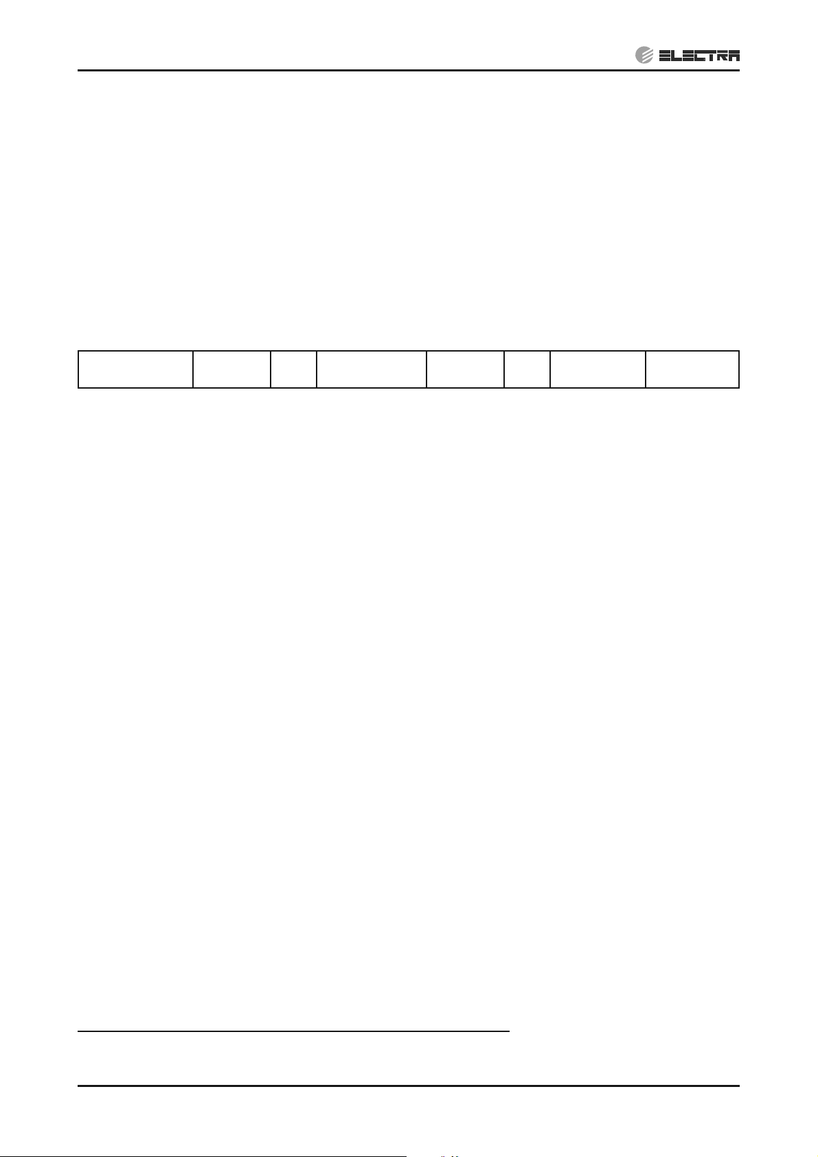
DC Inverter 10.0 / 12.5 / 14.0 kW
CONTENTS
Outdoor Units Indoor Units
OU12 4HP DCI
OU12 5HP DCI
OU12 6HP DCI CD 140
DNG 100
EMD 100
DNG 125
EMD 125
SM OU12HP 2-E.2 GB
REFRIGERANT
NOVEMBER 2008
R410A
HEAT PUMP
Page 2
LIST OF EFFECTIVE PAGES
CONTENTS
LIST OF EFFECTIVE PAGES
Note: Changes in the pages are indicated by a “Revision#” in the footer of each effected page
(when none indicates no changes in the relevant page). All pages in the following list represent
effected/ non effected pages divided by chapters.
Dates of issue for original and changed pages are:
Original ....... 0 ........ February 2007
Total number of pages in this publication is 215 consisting of the following:
Page
No.
Title .......................2
A ...........................2
i ............................. 2
1-1 - 1-3 ................2
2-1 - 2-5 ................2
3-1 ........................2
4-1 - 4-3 ................2
5-1 - 5-23 ..............2
6-1 - 6-3 ................2
7-1 - 7-4 ................2
8-1 ........................2
9-1 - 9-6 ................2
10-1 ......................2
11-1 .......................2
12-1-12-26 ............ 2
13-1-13-23 ............ 2
14-1-14-20 ............ 2
15-1-15-18 ............ 2
16-1-16-6 .............. 2
17-1-17-68 ............ 2
Revision
No. #
Page
No.
Revision
No. #
Page
No.
Revision
No. #
Zero in this column indicates an original page.
* Due to constant improvements please note that the data on this service manual can be modified with out notice.
** Photos are not contractual.
A
SM OU12HP 2-E.2 GB
Page 3

TABLE OF CONTENTS
Table of Contents
1. INTRODUCTION ...................................................................................................1-1
2. PRODUCT DATA SHEET ......................................................................................2-1
3. RATING CONDITIONS ..........................................................................................3-1
4. OUTLINE DIMENSIONS .......................................................................................4-1
5. PERFORMANCE DATA & PRESSURE CURVES ................................................5-1
6. AIRFLOW CURVES ..............................................................................................6-1
7. SOUND LEVEL CHARACTERISTICS ..................................................................7-1
8. ELECTRICAL DATA ..............................................................................................8-1
9. WIRING DIAGRAMS .............................................................................................9-1
10. REFRIGERATION DIAGRAMS .............................................................................10-1
11. TUBING CONNECTIONS ......................................................................................11-1
12. CONTROL SYSTEM .............................................................................................12-1
13. TROUBLESHOOTING ..........................................................................................13-1
14. SERVICING ...........................................................................................................14-1
15. EXPLODED VIEWS AND SPARE PARTS LISTS .................................................15-1
16. OPTIONAL ACCESSORIES .................................................................................16-1
APPENDIX A .........................................................................................................17-1
17.
SM OU12HP 2-E.2 GB
i
Page 4
1. INTRODUCTION
CONTENTS
1.1 General
The new 4-5-6HP DC INVERTER ducted split unit range comprises the following RC
(heat pump) models:
• DNG 100
• DNG 125
• EMD 100
• EMD 125
• CD 140
Remote control compatibility
The units are compatible with remote controls RC3, RC4, RCW1, RCW2, RC7.
Inverter description
Unlike standard units (fix RPM) that are selected according to their nominal capacity to
overcome the maximum required load, DC Inverter units can be selected to a smaller
nominal capacity range unit.
It made possible due to the ability of inverters to reach a much higher capacity level
(indicated as Maximum Capacity) which is around 115-130% of the nominal capacity.
1.2 Main Features
INTRODUCTION
High Technology
• Sine wave DC Compressor drive.
• DC-BL-SL (DC Brush-Less Sensor less) Inverter Compressor.
• DC-BL Inverter Outdoor Fan.
• Fuzzy Logic Adaptive Control.
System Features
• Variable cooling and heating capacity from 30% to 115% (of rated capacity).
• High COP “A-B” class energy rating (Most units).
• Low noise levels.
• Pre-charged system up to 30m.
• Tubing up to 70m length / 30m height difference.
• Networking connectivity.
• Current limitation setting for circuit breaker size reduction (if required).
• Dry contact inputs:
Standby.
Night mode (for silent operation in cooling).
Power Shedding (to control maximum power consumption).
SM OU12HP 2-E.2 GB
• Dry contact output:
Alarm
Base Heater
Crank Case Heater
1-1
Page 5
INTRODUCTION
CONTENTS
• HMI Display consists of 7-segments shows system diagnostics and setup.
• Monitoring software (PC port for high level service).
• Cooling operation at outdoor temperature down to -10°C.
• Heating operation at outdoor temperature down to -15°C.
• Up to 100Pa (4-5HP) and 200Pa (6HP) External static pressure.
1.3 Indoor Unit
The DNG DCI indoor unit is a low silhouette ducted unit, and can be easily fitted to many
type of residential and commercials applications.
• Low silhouette units 300 mm height.
• High technology plastic fan and fan housing.
• Drain pool at bottom of unit with internal downward slope.
• Over-flow switch, stops compressor operation in case of a blocked drainage.
• Bended coil hydrophilic coated aluminum fins.
• 3-speed fan motor and an extra speed in case a higher external static pressure re-
quired.
• Tubing connections at the back of the unit to allow easy outlet to both sides of the
unit.
• Easy installation and service access.
• Infrared remote control with liquid display unit (LCD).
• Field options:
(1) External water pump.
(2) Airconet connection.
(3) Plenum kit for connection of flexible duct hoses at air outlet.
1.4 Filtration
• The unit is equipped with pre filters.
• Easy and versatile access, rear or bottom, can be easily adjusted by the installer.
1.5 Control
The micro processor indoor controller, and an infrared remote control, supplied as
standard, provides complete operating function and programming.
For further details, please refer to the Operation Manual, Appendix A.
1.6 Outdoor Unit
1-2
The DCI outdoor units can be installed as floor or wall mounted units by using a wallsupporting bracket. The metal sheets are protected by anti- corrosion paint work allowing
long life resistance. All outdoor units are pre-charged. For further information, please
refer to the Product Data Sheet, Chapter 2.
• Compressor mounted in a soundproofed compartment.
• Improved 3-blades axial fans for noise reduction.
• Outdoor coil with hydrophilic fins optimized for operation with R410A refrigerant.
SM OU12HP 2-E.2 GB
Page 6

• Fan grill air outlet.
CONTENTS
• Service valves” flare” type connection.
• Service ports for high/ low pressure measurement.
• Interconnecting wiring terminal blocks.
1.7 Tubing Connections
Flare type-interconnecting tubing to be produced on site.
Units can be installed with 70-meter pipe length and 30 meter height difference without
oil traps.
For further details, please refer to the Installation Manual, Chapter 17.
1.8 Accessories
No. Item
1. RCW Wall Mounted Remote Control
2. RCW2 (BMS) Wall Mounted Remote Control
3. Base Heater
4. Crank case Heater
5. Room thermostat
INTRODUCTION
For further details, please refer the Optional Accessories, Chapter 16.
1.9 Inbox Documentation
Each unit includes its own installation and operation manuals.
1.10 Matching Table
1.10.1 R410A
OUTDOOR
UNITS
MODEL
DCI 4HP
DNG 100
INDOOR UNITS
DCI
DNG 125
DCI
EMD 100
DCI
EMD 125
DCI
CD140 DCI
SM OU12HP 2-E.2 GB
DCI 5HP
DCI 6HP
1-3
Page 7

PRODUCT DATA SHEET
CONTENTS
2. PRODUCT DATA SHEET
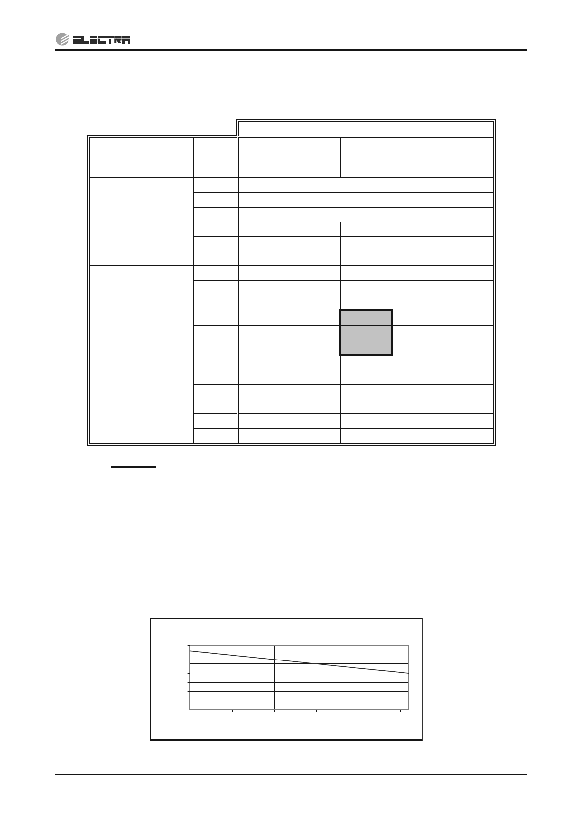
2.1 DNG 100 DCI / OU12 4HP DCI
Model Indoor Unit DNG 100 DCI
Model Outdoor Unit OU12 4HP DCI
Installation Method DUCTED
Characteristics Units Cooling Heating
Capacity - Nominal (Minimum ~ Maximum)
Power input - Nominal (Minimum ~ Maximum)
EER (Cooling) or COP(Heating)
(1)
(1)
(1)
Energy Efficiency Class “A” “C”
Power supply V/Ph/Hz 230 / 1 / 50
Rated current (Nominal) A 14.0 15.2
Starting current A 10
Circuit breaker rating A 25
Fan type & quantity Centrifugal x 1
Fan speeds H/M/L RPM 890 / 800 / 670
Air flow
(2)
H/M/L m3/hr 2170 / 1880 / 1440
External static pressure Min-Max Pa 20 -100
Sound power level
(3)
Sound pressure level
(4)
H/M/L dB(A) 71 / 67 / 62
H/M/L dB(A) 52 / 49 / 47
Moisture removal (Nominal) l/hr 3.3
Condensate drain tube I.D mm 19
INDOOR
Dimensions WxHxD mm 854/297/816
Weight kg 33
Package dimensions WxHxD mm 1010/342/917
Packaged weight kg 38
Units per pallet units 6
Stacking height units 6
Refrigerant control Electronic Expansion Valve
Compressor type, model Scroll
Motor type DCBL Inverter
Fan type & quantity Axial 2 x 493 Ømm
Fan speeds H/L RPM 900 – 100 (Continuous)
Airflow Max m3/hr 5.200
Sound power level
Sound pressure level
(3)
(4)
Nom C/H dB(A) 67 / 69
Nom C/H dB(A) 56 / 57
Dimensions WxHxD mm 900 / 1255 / 340
Weight kg 110
Package dimensions WxHxD mm 985 / 1395 / 435
Packaged weight kg 120
Units per pallet Units 1
OUTDOOR
Stacking height units 1
Refrigerant type R410A
Refrigerant charge(standard connecting tubing
length)
Additional charge per 1 meter g/m 38
Liquid line In.(mm) 3/8" (9.52)
Connections between
units
Suction line In.(mm) 5/8" (15.875)
Max.Tubing Length m. 70
Max.Height Difference m. 30
Operation control type LCD Remote control
Heating elements kW
Others
(1)
Rating conditions in accordance with ISO 5151 and ISO 13253 (for ducted units).
(2)
Airflow in ducted units; at nominal external static pressure.
(3)
Sound power in ducted units is measured at air discharge.
(4)
Sound pressure level measured at 1.0 meter distance from unit.
Btu/hr 34100(10900÷39200) 38200(9200 ÷ 42650)
kW 10.0(3.8 ÷ 11.5) 11.2(2.6 ÷ 12.5)
kW 3.125(1.400 ÷ 4.400) 3.390(1.000 ÷ 4.450)
W/W 3.2 3.3
Kg(m) 2.9 / 30
—
SM OU12HP 2-E.2 GB
2-1
Page 8
PRODUCT DATA SHEET
CONTENTS
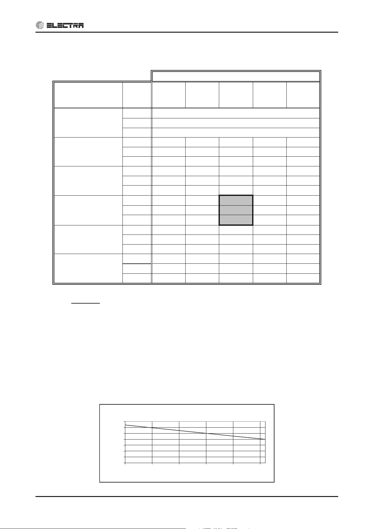
2.2 DNG 125 DCI / OU12 5HP DCI
Model Indoor Unit DNG 125 DCI
Model Outdoor Unit OU12 5HP DCI
Installation Method Ducted
Characteristics Units Cooling Heating
Capacity - Nominal (Minimum ~ Maximum)
Power input - Nominal (Minimum ~ Maximum)
EER (Cooling) or COP(Heating)
(1)
(1)
(1)
Energy efficiency class “B” “C”
Power supply V/Ph/Hz 230 / 1 / 50
Rated current (Nominal) A 19.7 19.0
Starting current A 10
Circuit breaker rating A 32
Fan type & quantity Centrifugal x 1
Fan speeds H/M/L RPM 935 / 855 / 760
Air flow
(2)
H/M/L m3/hr 2160 / 1950 / 1620
External static pressure Min-Max Pa 30-100
Sound power level
(3)
Sound pressure level
(4)
H/M/L dB(A) 71 / 67 / 62
H/M/L dB(A) 52 / 49 / 47
Moisture removal (Nominal) l/hr 4.6
Condensate drain tube I.D mm 19
INDOOR
Dimensions WxHxD mm 854 / 297 / 816
Weight kg 33
Package dimensions WxHxD mm 1010 / 342 / 917
Packaged weight kg 38
Units per pallet units 6
Stacking height units 6
Refrigerant control Electronic Expansion Valve
Compressor type, model Scroll
Motor type DCBL Inverter
Fan type & quantity Axial 2 x 493 Ømm
Fan speeds H/L RPM 900 – 100 (Continuous)
Air flow H/L m3/hr 5,700
Sound power level
(3)
Sound pressure level
(4)
Nom C/H dB(A) 69 / 70
Nom C/H dB(A) 56 / 58
Dimensions WxHxD mm 900 / 1255 / 340
Weight kg 110
Package dimensions WxHxD mm 985 / 1395 / 435
Packaged weight kg 120
Units per pallet Units 1
OUTDOOR
Stacking height units 1
Refrigerant type R410A
Refrigerant charge(standard connecting
tubing length)
Additional charge per 1 meter g/m 38
Liquid line In.(mm) 3/8" (9.52)
Connections
between units
Suction line In.(mm) 3/4" (19.0)
Max.Tubing Length m. 70
Max.Height Difference m. 30
Operation control type LCD Remote control
Heating elements kW
Others
(1)
Rating conditions in accordance with ISO 5151 and ISO 13253 (for ducted units).
(2)
Airflow in ducted units; at nominal external static pressure.
(3)
Sound power in ducted units is measured at air discharge.
(4)
Sound pressure level measured at 1.0 meter distance from unit.
Btu/hr 42650(16050÷47750) 47750(15000÷54600)
kW 12.5 (4.7 ÷ 14.0) 14.0 (4.4 ÷ 16.0)
kW 4.170 (1.500 ÷ 5.700) 4.300 (1.100 ÷ 5.500)
W/W 3.0 3.25
Kg(m) 3.1 / 30
2-2
SM OU12HP 2-E.2 GB
Page 9
PRODUCT DATA SHEET
CONTENTS
2.3 EMD 100 DCI / OU12 4HP DCI
Model Indoor Unit EMD 100 DCI
Model Outdoor Unit OU12 4HP DCI
Installation Method DUCTED
Characteristics Units Cooling Heating
Capacity - Nominal (Minimum ~ Maximum)
Power input - Nominal (Minimum ~ Maximum)
EER (Cooling) or COP(Heating)
(1)
(1)
(1)
Energy efficiency class “A” “A”
Power supply V/Ph/Hz 230 / 1 / 50
Rated current (Nominal) A 14.0 14.2
Starting current A 10
Circuit breaker rating A 25
Fan type & quantity Centrifugal x 1
Fan speeds H/M/L RPM 1060 / 1000 / 840
Air flow
(2)
H/M/L m3/hr 1980 / 1820 / 1390
External static pressure Min-Max Pa 20-100
Sound power level
(3)
Sound pressure level
(4)
H/M/L dB(A) 73 / 71 / 65
H/M/L dB(A) 52 / 50 / 45
Moisture removal (Nominal) l/hr 3.1
Condensate drain tube I.D mm 19
INDOOR
Dimensions WxHxD mm 790X400X600
Weight kg 36
Package dimensions WxHxD mm 825X425X610
Packaged weight kg 38
Units per pallet units 8
Stacking height units 4
Refrigerant control Electronic Expansion Valve
Compressor type, model Scroll
Motor type DCBL Inverter
Fan type & quantity Axial 2 x 493 Ømm
Fan speeds H/L RPM 900 – 100 (Continuous)
Airflow Max m3/hr 5,200
Sound power level
(3)
Sound pressure level
(4)
Nom C/H dB(A) 67 / 69
Nom C/H dB(A) 56 / 57
Dimensions WxHxD mm 900X1255X340
Weight kg 110
Package dimensions WxHxD mm 985X1395X435
Packaged weight kg 120
OUTDOOR
Units per pallet Units 1
Stacking height units 1
Refrigerant type R410A
Refrigerant charge(standard connecting
tubing length)
Additional charge per 1 meter g/m 38
Liquid line In.(mm) 3/8" (9.52)
Connections
between units
Suction line In.(mm) 5/8" (15.875)
Max.tubing length m. 70
Max.height difference m. 30
Operation control type LCD Remote control
Heating elements kW
Others
(1)
Rating conditions in accordance with ISO 5151 and ISO 13253 (for ducted units).
(2)
Airflow in ducted units; at nominal external static pressure.
(3)
Sound power in ducted units is measured at air discharge.
(4)
Sound pressure level measured at 1.0 meter distance from unit.
Btu/hr 34,100 (10,250-40,950) 39,250 (12,000-42,650)
kW 10.0 (3.0-12.0) 11.5(3.5-12.5)
kW 3.05 (1.30-4.20) 3.10 (1.10-3.60)
W/W 3.30 3.70
Kg(m) 2.9 / 30
—
SM OU12HP 2-E.2 GB
2-3
Page 10
PRODUCT DATA SHEET
CONTENTS
2.4 EMD 125 DCI / OU12 5HP DCI
Model Indoor Unit EMD 125 DCI
Model Outdoor Unit OU12 5HP DCI
Installation Method DUCTED
Characteristics Units Cooling Heating
Capacity - Nominal (Minimum ~ Maximum)
Power input - Nominal (Minimum ~ Maximum)
EER (Cooling) or COP(Heating)
(1)
(1)
(1)
Energy efficiency class B B
Power supply V/Ph/Hz 230 / 1 / 50
Rated current A 18.8 18.6
Starting current A 10
Circuit breaker rating A 32
Fan type & quantity Centrifugal x 1
Fan speeds H/M/L RPM 930 / 830 / 740
Air flow
(2)
H/M/L m3/hr 2500 / 2100 / 1600
External static pressure Min-Max Pa 20-100
Sound power level
(3)
Sound pressure level
(4)
H/M/L dB(A) 72 / 68 / 64
H/M/L dB(A) 54 / 51 / 45
Moisture removal (Nominal) l/hr 3.8
Condensate drain tube I.D mm 19
INDOOR
Dimensions WxHxD mm 1150X400X700
Weight kg 46
Package dimensions WxHxD mm 1195X440X730
Packaged weight kg 50
Units per pallet units 8
Stacking height units 4
Refrigerant control Electronic Expansion Valve
Compressor type, model Scroll
Motor type DCBL Inverter
Fan type & quantity Axial 2 x 493 Ømm
Fan speeds H/L RPM 900 – 100 (Continuous)
Air flow Max m3/hr 5,700
Sound power level
(3)
Sound pressure level
(4)
Nom C/H dB(A) 69 / 70
Nom C/H dB(A) 56 / 58
Dimensions WxHxD mm 900X1255X340
Weight kg 110
Package dimensions WxHxD mm 985X1395X435
Packaged weight kg 120
Units per pallet Units 1
OUTDOOR
Stacking height units 1
Refrigerant type R410A
Refrigerant charge(standard connecting
tubing length)
Additional charge per 1 meter g/m 38
Liquid line In.(mm) 3/8" (9.52)
Connections
between units
Suction line In.(mm) 3/4" (19.0)
Max.tubing length m. 70
Max.height difference m. 30
Operation control type LCD Remote control
Heating elements kW
Others
(1)
Rating conditions in accordance with ISO 5151 and ISO 13253 (for ducted units).
(2)
Airflow in ducted units; at nominal external static pressure.
(3)
Sound power in ducted units is measured at air discharge.
(4)
Sound pressure level measured at 1.0 meter distance from unit.
Btu/hr 42,650 (11,940-47,770) 47,770 (12,280-54,590)
kW 12.5 (3.5-14.0) 14.0 (3.6-16.0)
kW 4.1 (1.65-5.5) 4.1 (1.1-5.2)
W/W 3.05 3.4
Kg(m) 3.3 / 30
—
2-4
SM OU12HP 2-E.2 GB
Page 11
PRODUCT DATA SHEET
CONTENTS
2.5 CD 140 DCI / OU12 6HP DCI
Model Indoor Unit CD 140 DCI
Model Outdoor Unit OU12 6HP DCI
Installation Method DUCTED
Characteristics Units Cooling Heating
Capacity - Nominal (Minimum ~ Maximum)
Power Input - Nominal (Minimum ~ Maximum)
(1)
COP
(1)
( (1)
Energy Efficiency Class - A A
Power Supply V/Ph/Hz 220-240/1/50
Rated Current (Nominal) A 21.6 20.3
Starting Current A <10
Circuit Breaker Rating A 32
Fan Type & Quantity CENTRIFUGAL x2
Fan Speed H/M/L RPM 1,160 1,120 1,000
(2)
Airflow
H/M/L m3/hr 3,300 2,900 2,000
Min-
External Static Pressure
Sound Power Level
(3)
Sound Pressure Level
(4)
Nom-
Max
H/M/L dB (A) 73 71 66
H/M/L dB (A) 58 55 50
Moisture Removal (Nominal) L/hr 4.0
Condensate Drain Tube I.D. mm 19
INDOOR
Dimensions W/H/D mm 1350 400 640
Weight kg 75
Package Dimensions W/H/D mm 1510 440 785
Packaged Weight kg 82
Units per Pallet Units 5
Stacking Height Units 5
Refrigerant Control Electronic Expansion Valve
Compressor Type, Model Twin-Rotary
Motor type DCBL Inverter
Fan Type & Quantity Axial 2x 493mm
Fan Speed RPM 900-100 (continuous)
Airflow Max m
Sound Power Level Nom dB (A) 68 70
Sound Pressure Level
(4)
Nom dB (A) 56 58
Dimensions W/H/D mm 900 1255 340
Weight kg 110
Package Dimensions W/H/D mm 985 1395 435
Packaged Weight kg 120
OUTDOOR
Units per Pallet Units 1
Stacking Height Units 1
Refrigerant Type R410A
Refrigerant Chargeless Distance kg/m 3.8 / 30
Additional Charge Per 1 Meter g/m 80
Liquid Line In 3/8”
Connections
Between Units
Suction Line In 3/4”
Max. Tubing Length m 70
Max. Height Difference m 30
Operation Control Type LCD Remote Control
Heating Elements kW BH 70W - optional
Others
Btu/hr 47,770 (15,700 - 56,300) 54,600 (12,600 – 63,100)
kW 14.0 (4.6 – 16.5) 16.0 (3.7 – 18.5)
W 4,200 (1,500 - 6,000) 4,400 (1,200 - 5,500)
W/W 3.3 3.6
Pa 80-140-200
3
/hr 5,700
SM OU12HP 2-E.2 GB
(1)
Rating conditions in accordance with ISO 5151 and ISO 13253 (for ducted units).
(2)
Airflow in ducted units; at nominal external static pressure.
(3)
Sound power in ducted units is measured at air discharge.
(4)
Sound pressure level measured at 1.0 meter distance from unit.
2-5
Page 12

3. RATING CONDITIONS
CONTENTS
Standard conditions in accordance with ISO 5151 and ISO 13253 (for ducted units) and
EN 14511.
RATING CONDITIONS
Cooling:
Indoor: 27
Outdoor: 35
o
C DB 19oC WB
o
C DB
Heating:
Indoor: 20
Outdoor: 7
o
C DB
o
C DB 6oC WB
3.1 Operating Limits
Cooling
Heating
Voltage 1PH 198 – 253V
Upper limit 32
Lower limit 21
Upper limit 27
Lower limit 10
Indoor Outdoor
o
C DB 23oC WB 46oC DB
o
C DB 15oC WB -10oC DB
o
C DB 24oC DB 18oC WB
o
C DB -15oC DB -16oC WB
SM OU12HP 2-E.2 GB
3-1
Page 13

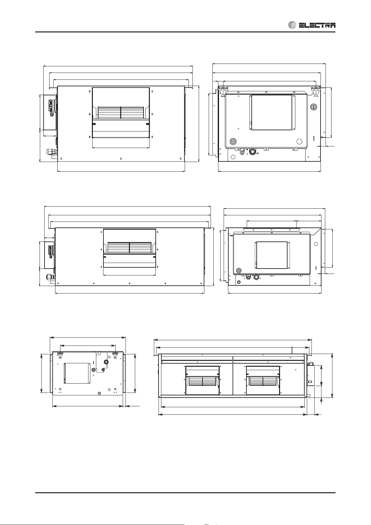
4. OUTLINE DIMENSIONS
CONTENTS
4.1 Indoor Unit: DNG 100, DNG 125 DCI
OUTLINE DIMENSIONS
DNG 100, 125
SM OU12HP 2-E.2 GB
Model A B C D E F G H I J K L
854 715 815 822 861 297 235 770 663 749 193 282
4-1
Page 14
OUTLINE DIMENSIONS
CONTENTS
4.2 Indoor Unit: EMD 100 DCI
097
557
017
187
96
166
Indoor Unit: EMD 125 DCI
4.3
96
003
076
0511
0211
0901
400
2
325x610
006
075
5
094
045
007
076
043 0
264
52
71
187118
063
5201
Indoor Unit: CD 140 DCI
t4.4
690
500
352
640
352
25
400
350x995
1435
1390
1303
1350
264
52
046
400
108 187
69
4-2
SM OU12HP 2-E.2 GB
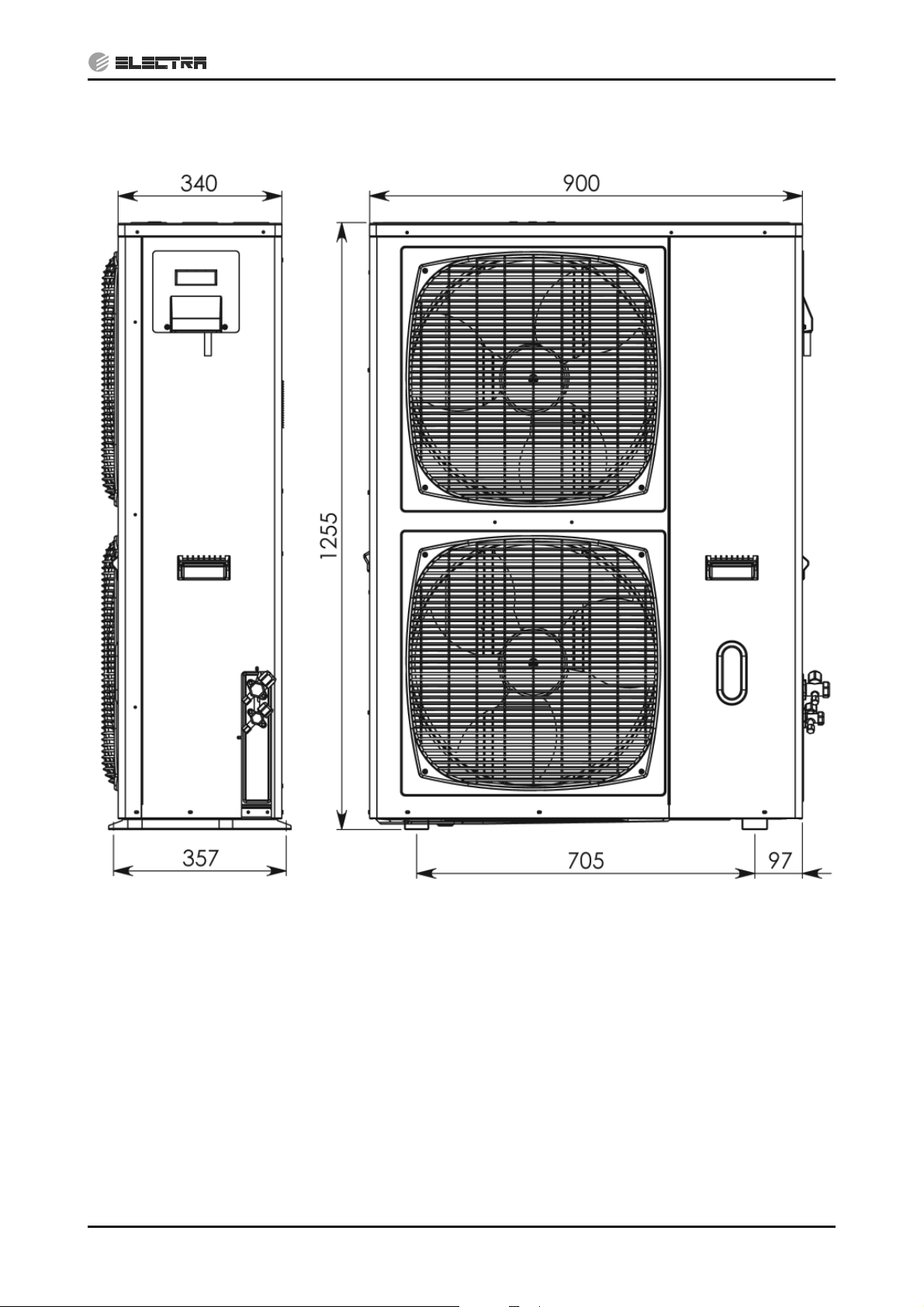
Page 15
OUTLINE DIMENSIONS
CONTENTS
4.4 Outdoor Unit: DCI 100 / 125 / 140 (OU12 DCI 4-5-6HP)
SM OU12HP 2-E.2 GB
4-3
Page 16
PERFORMANCE DATA & PRESSURE CURVES
CONTENTS
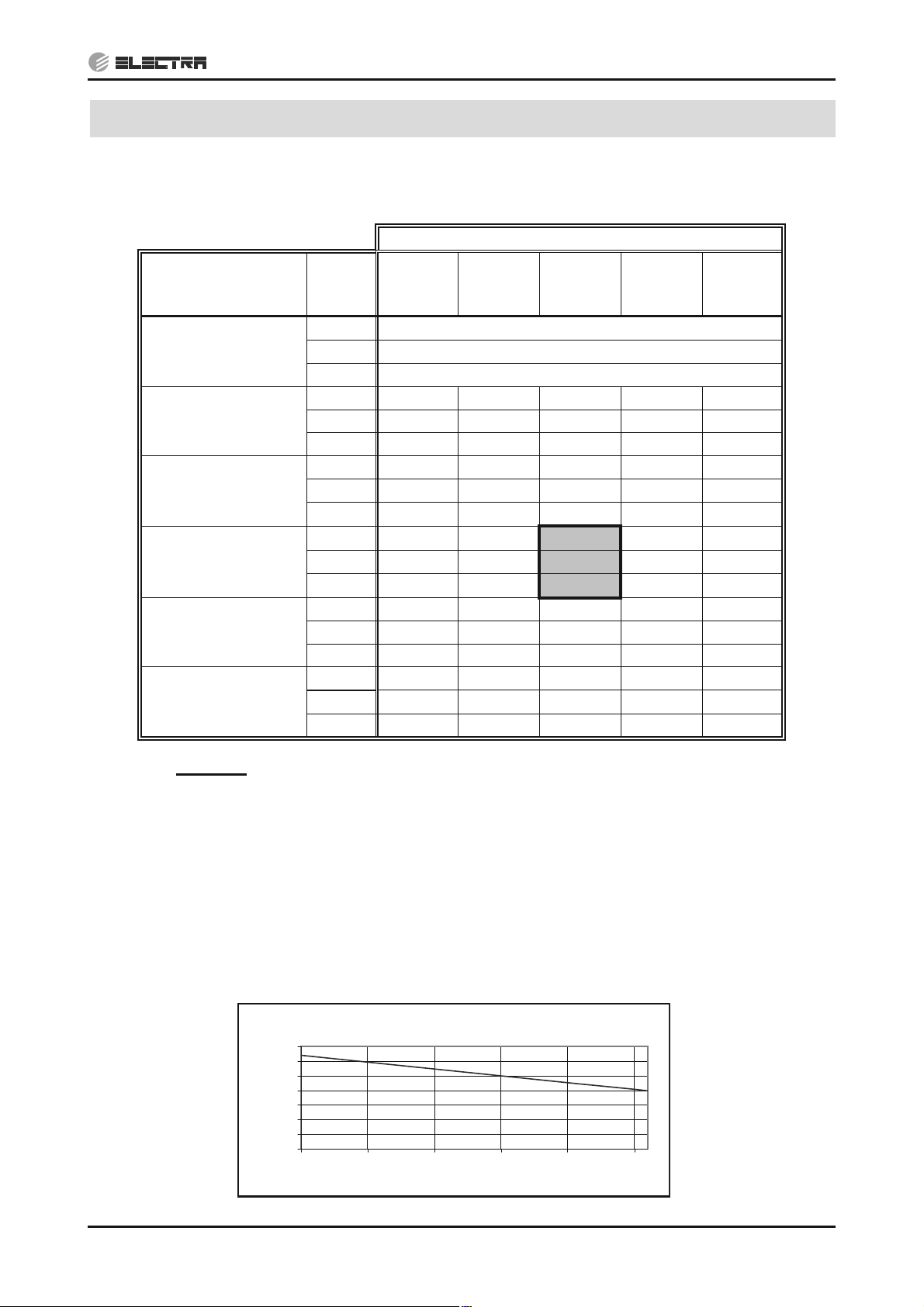
5. PERFORMANCE DATA & PRESSURE CURVES
5.1 DNG 100 DCI
5.1.1 Cooling Capacity (kW)
OD COIL
ENTERING AIR DB
TEMPERATURE [qC]
-10 – 20
(protection range)
25
30
35
40
46
ID COIL ENTERING AIR DB/WB TEMPERATURE [qC]
DATA
22/15 24/17 27/19 29/21 32/23
TC 80 - 110 % of nominal
SC 80 - 105 % of nominal
PI 25 - 50 % of nominal
TC 9.67 10.30 10.93 11.56 12.19
SC 7.67 7.83 7.99 8.14 8.30
PI 2.46 2.50 2.55 2.60 2.64
TC 9.20 9.83 10.47 11.10 11.73
SC 7.48 7.64 7.79 7.95 8.11
PI 2.74 2.79
TC 8.74 9.37
2.84
10.00
2.88 2.93
10.63 11.26
SC 7.29 7.44 7.60 7.76 7.91
PI 3.03 3.08
TC 8.27 8.90
3.13
9.54
3.17 3.22
10.17 10.80
SC 7.09 7.25 7.41 7.56 7.72
PI 3.32 3.37 3.41 3.46 3.51
TC
SC
7.71 8.35 8.98 9.61 10.24
6.86 7.02 7.17 7.33 7.49
PI 3.66 3.71 3.76 3.80 3.85
LEGEND
TC – Total Cooling Capacity, kW
SC – Sensible Capacity, kW
PI – Power Input, kW
WB – Wet Bulb Temp., (
DB – Dry Bulb Temp., (
o
o
C)
C)
ID – Indoor
OD – Outdoor
5.1.2 Capacity Correction Factors (Cooling)
Cooling Capacity Ratio Vs. Outdoor Temperature
1.20
1.10
1.00
0.90
0.80
0.70
Capacity Ratio
0.60
0.50
20 25 30 35 40 45
Outdoor Temperature [deg C]
SM OU12HP 2-E.2 GB
5-1
Page 17
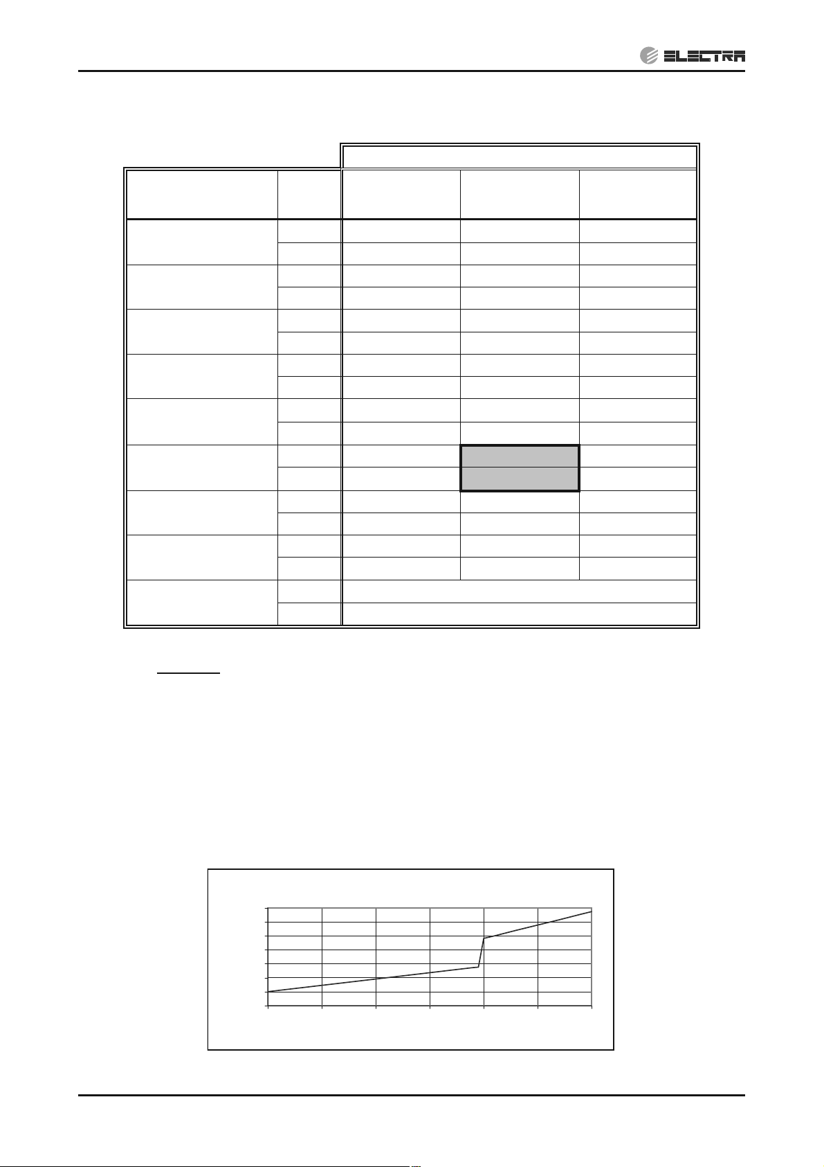
PERFORMANCE DATA & PRESSURE CURVES
CONTENTS
5.1.3 Heating Capacity
ID COIL ENTERING AIR DB TEMPERATURE [°C]
OD COIL ENTERING
AIR DB/WB
TEMPERATURE [°C]
-15/-16
-10/-12
-7/-8
-1/-2
2/1
7/6
10/9
15/12
15-24
(Protection Range)
DATA
TC 7.13 6.63 6.13
PI 2.03 2.24 2.45
TC 7.94 7.44 6.94
PI 2.45 2.66 2.87
TC 8.54 8.04 7.54
PI 2.77 2.97 3.18
TC 8.84 8.34 7.85
PI 2.92 3.13 3.34
TC 9.04 8.55 8.05
PI 3.03
TC 11.70
PI 3.18
TC 12.34
PI 3.37 3.58 3.79
TC 12.99 12.49 11.99
PI 3.56 3.77 3.98
TC 85 - 105 % of nominal
PI 80 - 120 % of nominal
15 20 25
3.23
11.20
3.39
11.85
3.44
10.70
3.60
11.35
LEGEND
TH – Total Heating Capacity, kW
PI – Power Input, kW
o
WB – Wet Bulb Temp., (
DB – Dry Bulb Temp., (
o
C)
C)
ID – Indoor
OD – Outdoor
5.1.4 Capacity Correction Factors (Heating)
Heating Capacity Ratio Vs. Outdoor Temperature
1.20
1.10
1.00
0.90
0.80
0.70
0.60
Capacity Ration
0.50
-15 -10 -5 0 5 10 15
Outdoor WB Temperature [deg C]
5-2
SM OU12HP 2-E.2 GB
Page 18
PERFORMANCE DATA & PRESSURE CURVES
CONTENTS
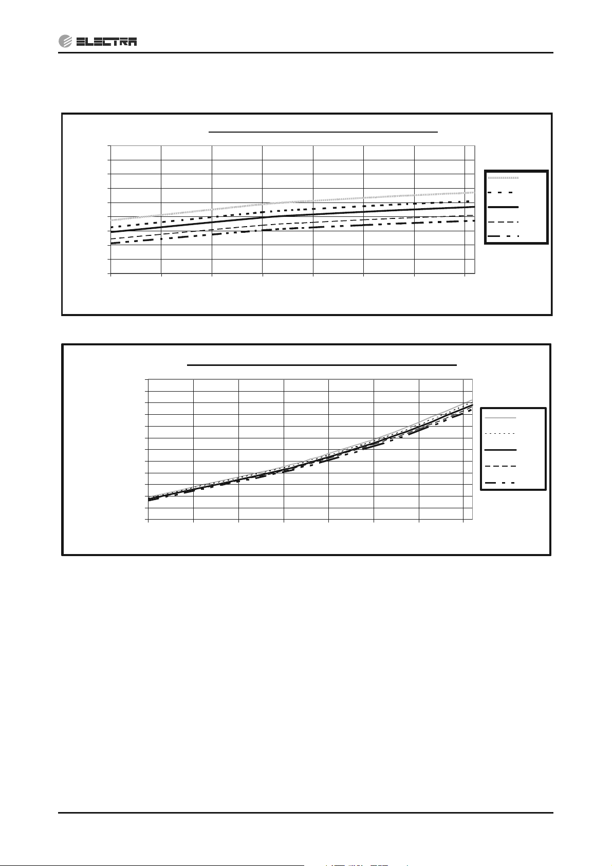
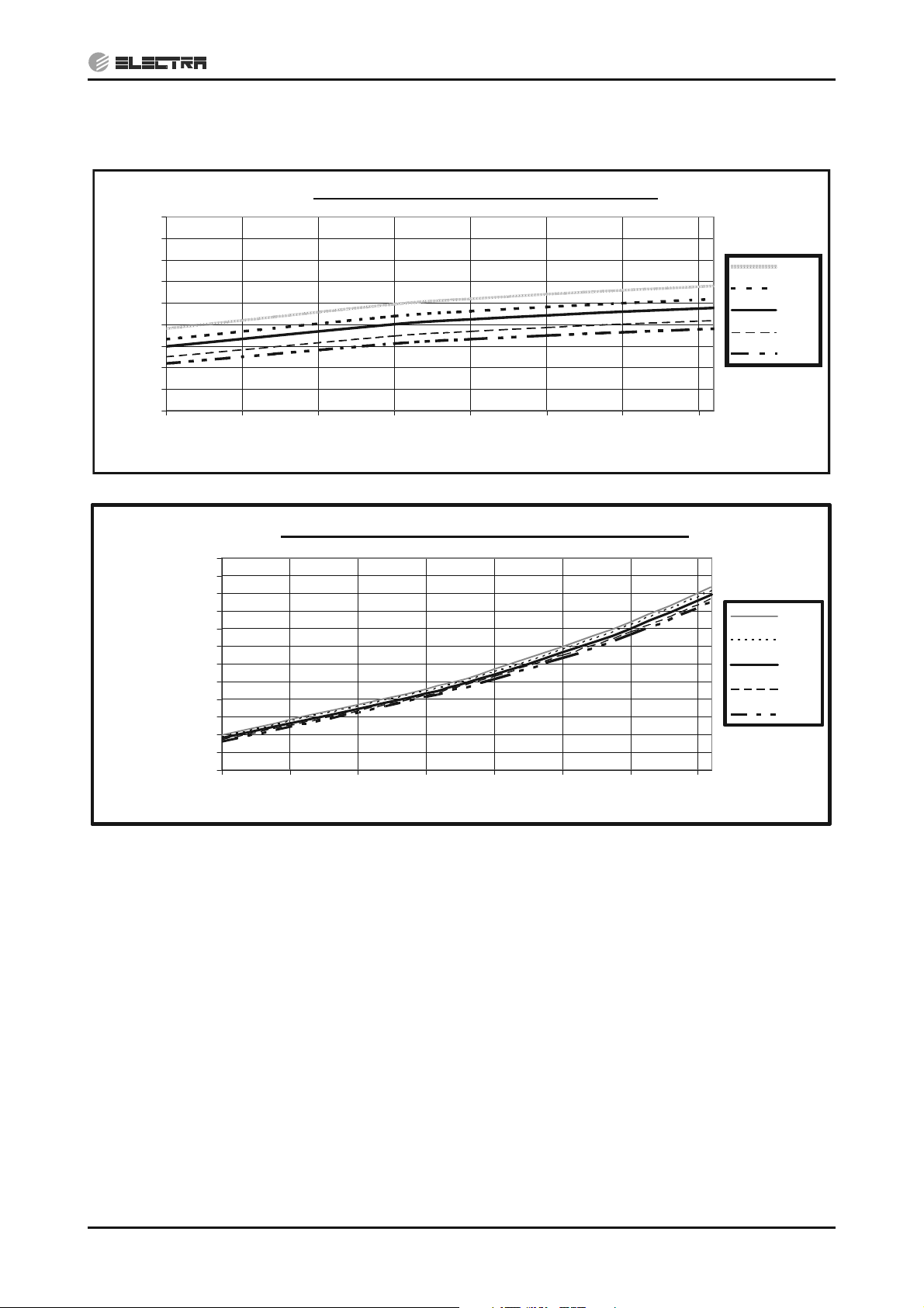
5.1.5 Pressure Curves (Cooling – Technician Mode)
5.1.5.1 Cooling
Suction Pressure - Cooling (Technician Mode)
1400
1300
1200
1100
1000
900
800
700
600
Suction Pressure [KPa(g)]
500
10 15 20 25 30 35 40 45
Outdoor DB Temperature [°C]
32/23
29/21
27/19
24/17
22/15
Discharge Pressure - Cooling (Technician Mode)
4000
3750
3500
3250
3000
2750
2500
[KPa(g)]
2250
2000
Discharge Pressure
1750
1500
1250
1000
10 15 20 25 30 35 40 45
Outdoor DB Temperature [°C]
32/23
29/21
27/19
24/17
22/15
SM OU12HP 2-E.2 GB
5-3
Page 19

PERFORMANCE DATA & PRESSURE CURVES
CONTENTS
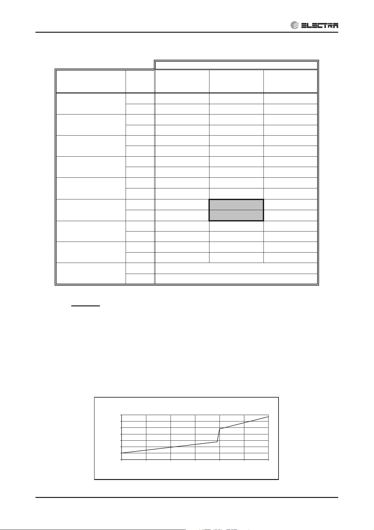
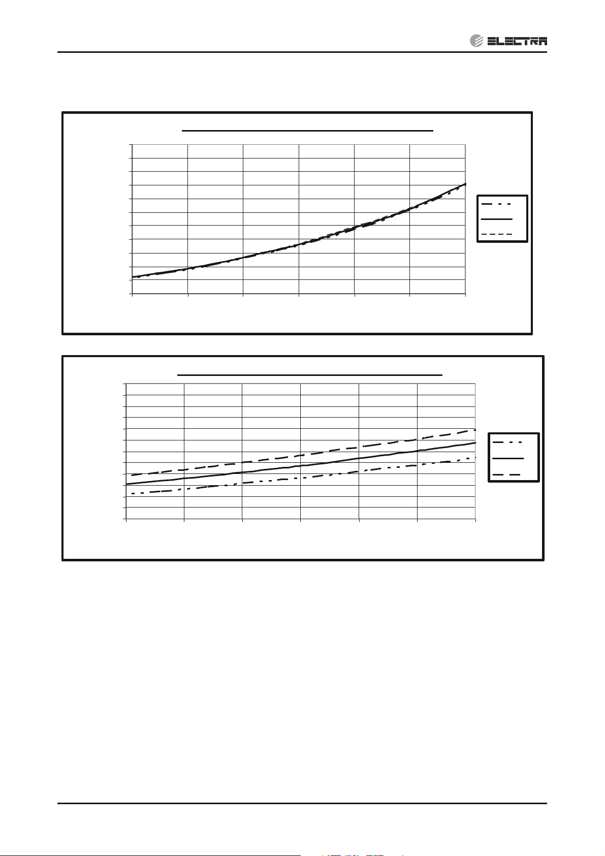
5.1.5.2 Heating
Suction Pressure - Heating (Technician Mode)
1300
1200
1100
1000
900
800
700
600
500
400
Suction Pressure [KPa(g)]
300
200
-15 -10 -5 0 5 10 15
Outdoor WB Temperature [°C]
15
20
25
Discharge Pressure - Heating (Technician Mode)
4000
3750
3500
3250
3000
2750
2500
[KPa(g)]
2250
2000
Discharge Pressure
1750
1500
1250
1000
-15-10-5 0 5 1015
Outdoor WB Tempera ture [°C]
15
20
25
5-4
SM OU12HP 2-E.2 GB
Page 20

5.2 DNG 125 DCI
CONTENTS
5.2.1 Cooling Capacity (kW)
PERFORMANCE DATA & PRESSURE CURVES
OD COIL
ENTERING AIR DB
TEMPERATURE [qC]
-10 – 20
(protection range)
25
30
35
40
46
ID COIL ENTERING AIR DB/WB TEMPERATURE [qC]
DATA
22/15 24/17 27/19 29/21 32/23
TC 80 - 110 % of nominal
SC 80 - 105 % of nominal
PI 25 - 50 % of nominal
TC 12.08 12.87 13.66 14.45 15.24
SC 9.59 9.79 9.98 10.18 10.38
PI 3.28 3.34 3.40 3.47 3.53
TC 11.50 12.29 13.08 13.87 14.66
SC 9.35 9.55 9.74 9.94 10.13
PI 3.66 3.72
TC 10.92 11.71
3.79
12.50
3.85 3.91
13.29 14.08
SC 9.11 9.30 9.50 9.70 9.89
PI 4.04 4.11
TC 10.34 11.13
4.17
11.92
4.23 4.30
12.71 13.50
SC 8.87 9.06 9.26 9.45 9.65
PI 4.43 4.49 4.55 4.62 4.68
TC
SC
9.64 10.43 11.22 12.01 12.80
8.58 8.77 8.97 9.16 9.36
PI 4.89 4.95 5.01 5.08 5.14
LEGEND
TC – Total Cooling Capacity, kW
SC – Sensible Capacity, kW
PI – Power Input, kW
WB – Wet Bulb Temp., (
DB – Dry Bulb Temp., (
o
o
C)
C)
ID – Indoor
OD – Outdoor
5.2.2 Capacity Correction Factors (Cooling)
Cooling Capacity Ratio Vs. Outdoor Temperature
1.20
1.10
1.00
0.90
0.80
0.70
Capacity Ratio
0.60
0.50
20 25 30 35 40 45
Outdoor Temperature [deg C]
SM OU12HP 2-E.2 GB
5-5
Page 21
PERFORMANCE DATA & PRESSURE CURVES
CONTENTS
5.2.3 Heating Capacity
ID COIL ENTERING AIR DB TEMPERATURE [°C]
OD COIL ENTERING
AIR DB/WB
TEMPERATURE [°C]
-15/-16
-10/-12
-7/-8
-1/-2
DATA
TC 8.91 8.20 7.67
PI 2.58 2.84 3.11
TC 9.92 9.30 8.67
PI 3.11 3.37 3.64
TC 10.68 10.05 9.43
PI 3.51 3.77 4.03
TC 11.05 10.43 9.81
PI 3.71 3.97 4.23
15 20 25
2/1
TC 11.31 10.68 10.06
PI 3.84
TC 14.62
7/6
PI 4.04
TC 15.43
10/9
PI 4.28 4.54 4.80
TC 16.24 15.61 14.99
15/12
PI 4.52 4.78 5.04
15-24
(Protection Range)
TC 85 - 105 % of nominal
PI 80 - 120 % of nominal
LEGEND
TH – Total Heating Capacity, kW
PI – Power Input, kW
o
WB – Wet Bulb Temp., (
DB – Dry Bulb Temp., (
o
C)
C)
ID – Indoor
OD – Outdoor
4.10
14.00
4.30
14.81
4.36
13.38
4.56
14.18
5.2.4 Capacity Correction Factors (Heating)
5-6
Heating Capacity Ratio Vs. Outdoor Temperature
1.20
1.10
1.00
0.90
0.80
0.70
0.60
Capacity Ration
0.50
-15 -10 -5 0 5 10 15
Outdoor WB Temperature [deg C]
SM OU12HP 2-E.2 GB
Page 22
PERFORMANCE DATA & PRESSURE CURVES
CONTENTS
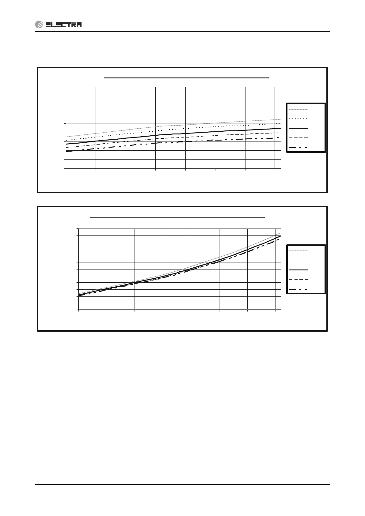
5.2.5 Pressure Curves (Cooling – Technician Mode)
5.2.5.1 Cooling
Suction Pressure - Cooling (Technician Mode)
1400
1300
1200
1100
1000
900
800
700
600
Suction Pressure [KPa(g)]
500
10 15 20 25 30 35 40 45
Outdoor DB Temperature [°C]
32/23
29/21
27/19
24/17
22/15
Discharge Pressure - Cooling (Technician Mode)
4000
3750
3500
3250
3000
2750
2500
2250
[KPa(g)]
2000
1750
Discharge Pressure
1500
1250
1000
10 15 20 25 30 35 40 45
Outdoor DB Temperature [°C]
32/23
29/21
27/19
24/17
22/15
SM OU12HP 2-E.2 GB
5-7
Page 23
PERFORMANCE DATA & PRESSURE CURVES
CONTENTS
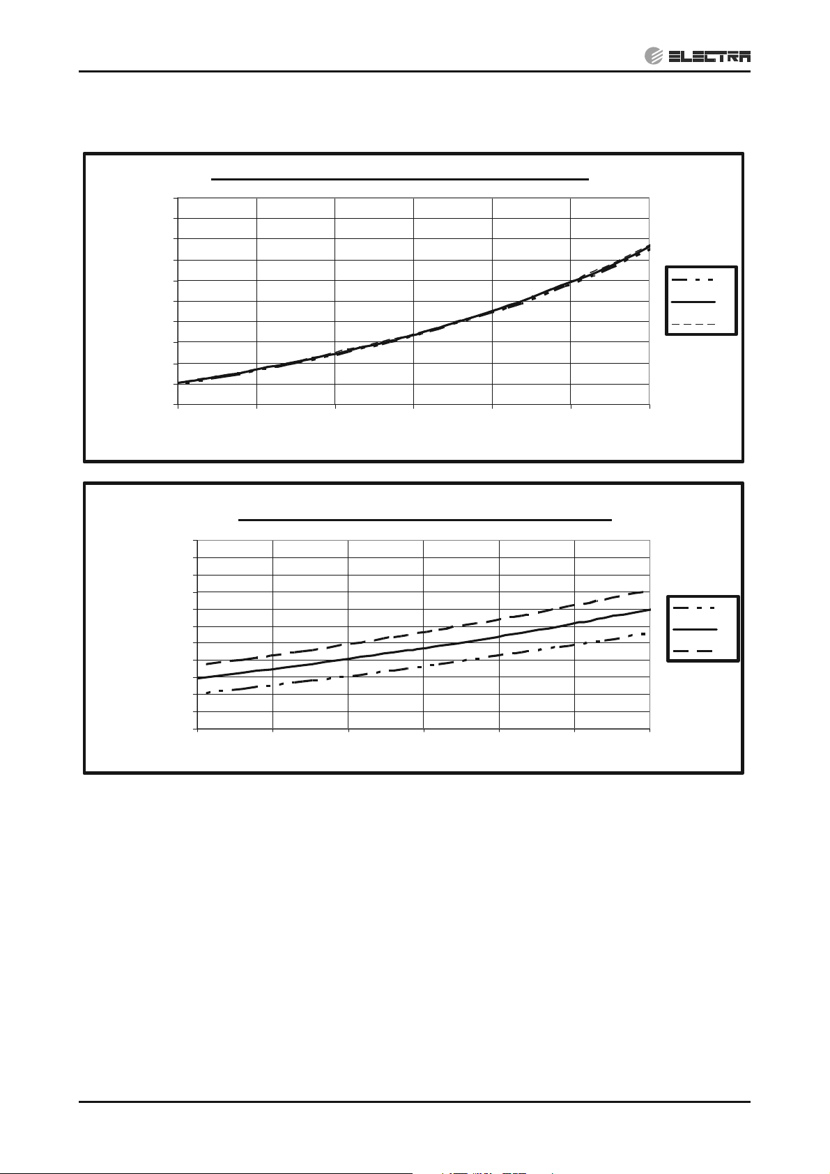
5.2.5.2 Heating
Suction Pressure - Heating (Technician Mode)
1200
1100
1000
900
800
700
600
500
400
Suction Pressure [KPa(g)]
300
200
-15 -10 -5 0 5 10 15
Outdoor WB Temperature [°C]
15
20
25
Discharge Pressure - Heating (Technician Mode)
3950
3700
3450
3200
2950
2700
2450
[KPa(g)]
2200
1950
1700
Discharge Pressure
1450
1200
-15 -10 -5 0 5 10 15
Outdoor WB Temperature [°C]
15
20
25
5-8
SM OU12HP 2-E.2 GB
Page 24
5.3 EMD 100 DCI
CONTENTS
5.3.1 Cooling Capacity (kW)
PERFORMANCE DATA & PRESSURE CURVES
OD COIL
ENTERING AIR DB
TEMPERATURE [qC]
-10 – 20
(protection range)
25
30
35
40
46
ID COIL ENTERING AIR DB/WB TEMPERATURE [qC]
DATA
22/15 24/17 27/19 29/21 32/23
TC 80 - 110 % of nominal
SC 80 - 105 % of nominal
PI 25 - 50 % of nominal
TC 9.67 10.30 10.93 11.56 12.19
SC 7.96 8.12 8.28 8.44 8.61
PI 2.40 2.44 2.49 2.53 2.58
TC 9.20 9.83 10.47 11.10 11.73
SC 7.76 7.92 8.08 8.24 8.41
PI 2.68 2.72
TC 8.74 9.37
2.77
10.00
2.82 2.86
10.63 11.26
SC 7.56 7.72 7.88 8.04 8.20
PI 2.96 3.00
TC 8.27 8.90
3.05
9.54
3.10 3.14
10.17 10.80
SC 7.35 7.52 7.68 7.84 8.00
PI 3.24 3.28 3.33 3.38 3.42
TC
SC
7.71 8.35 8.98 9.61 10.24
7.11 7.28 7.44 7.60 7.76
PI 3.58 3.62 3.67 3.71 3.76
LEGEND
TC – Total Cooling Capacity, kW
SC – Sensible Capacity, kW
PI – Power Input, kW
o
WB – Wet Bulb Temp., (
DB – Dry Bulb Temp., (
o
C)
C)
ID – Indoor
OD – Outdoor
5.3.2 Capacity Correction Factors (Cooling)
Cooling Capacity Ratio Vs. Outdoor Temperature
1.20
1.10
1.00
0.90
0.80
0.70
Capacity Ratio
0.60
0.50
20 25 30 35 40 45
Outdoor Temperature [deg C]
SM OU12HP 2-E.2 GB
5-9
Page 25

PERFORMANCE DATA & PRESSURE CURVES
CONTENTS
5.3.3 Heating Capacity
ID COIL ENTERING AIR DB TEMPERATURE [°C]
OD COIL ENTERING
AIR DB/WB
TEMPERATURE [°C]
-15/-16
-10/-12
-7/-8
-1/-2
2/1
7/6
10/9
15/12
15-24
(Protection Range)
DATA
TC 7.32 6.81 6.30
PI 1.86 2.05 2.24
TC 8.15 7.64 7.12
PI 2.24 2.43 2.62
TC 8.77 8.26 7.75
PI 2.53 2.72 2.91
TC 9.08 8.57 8.06
PI 2.67 2.86 3.05
TC 9.29 8.77 8.26
PI 2.77
TC 12.01
PI 2.91
TC 12.67
PI 3.08 3.27 3.46
TC 13.34 12.82 12.31
PI 3.26 3.45 3.64
TC 85 - 105 % of nominal
PI 80 - 120 % of nominal
15 20 25
2.96
11.50
3.10
12.16
3.15
10.99
3.29
11.65
LEGEND
TH – Total Heating Capacity, kW
PI – Power Input, kW
o
WB – Wet Bulb Temp., (
DB – Dry Bulb Temp., (
o
C)
C)
ID – Indoor
OD – Outdoor
5.3.4 Capacity Correction Factors (Heating)
Heating Capacity Ratio Vs. Outdoor Temperature
1.20
1.10
1.00
0.90
0.80
0.70
0.60
Capacity Ration
0.50
-15 -10 -5 0 5 10 15
Outdoor WB Temperature [deg C]
5-10
SM OU12HP 2-E.2 GB
Page 26
PERFORMANCE DATA & PRESSURE CURVES
CONTENTS
5.3.5 Pressure Curves (Cooling – Technician Mode)
5.3.5.1 Cooling
Suction Pressure - Cooling (Technician Mode)
1400
1300
1200
1100
1000
900
800
700
600
Suction Pressure [KPa(g)]
500
10 15 20 25 30 35 40 45
Outdoor DB Temperature [°C]
32/23
29/21
27/19
24/17
22/15
Discharge Pressure - Cooling (Technician Mode)
4000
3750
3500
3250
3000
2750
2500
[KPa(g)]
2250
2000
Discharge Pressure
1750
1500
1250
1000
10 15 20 25 30 35 40 45
Outdoor DB Temperature [°C]
32/23
29/21
27/19
24/17
22/15
SM OU12HP 2-E.2 GB
5-11
Page 27
PERFORMANCE DATA & PRESSURE CURVES
CONTENTS
5.3.5.2 Heating
Suction Pressure - Heating (Technician Mode)
1300
1200
1100
1000
900
800
700
600
500
400
Suction Pressure [KPa(g)]
300
200
-15 -10 -5 0 5 10 15
Outdoor WB Temperature [°C]
15
20
25
Discharge Pressure - Heating (Technician Mode)
4000
3750
3500
3250
3000
2750
2500
[KPa(g)]
2250
2000
Discharge Pressure
1750
1500
1250
1000
-15-10-5 0 5 1015
Outdoor WB Temperature [°C]
15
20
25
5-12
SM OU12HP 2-E.2 GB
Page 28
5.4 EMD 125 DCI
CONTENTS
5.4.1 Cooling Capacity (kW)
PERFORMANCE DATA & PRESSURE CURVES
OD COIL
ENTERING AIR DB
TEMPERATURE [qC]
-10 – 20
(protection range)
25
30
35
40
46
ID COIL ENTERING AIR DB/WB TEMPERATURE [qC]
DATA
22/15 24/17 27/19 29/21 32/23
TC 80 - 110 % of nominal
SC 80 - 105 % of nominal
PI 25 - 50 % of nominal
TC 12.08 12.87 13.66 14.45 15.24
SC 9.87 10.07 10.27 10.47 10.68
PI 3.22 3.28 3.35 3.41 3.47
TC 11.50 12.29 13.08 13.87 14.66
SC 9.62 9.82 10.02 10.23 10.43
PI 3.60 3.66
TC 10.92 11.71
3.72
12.50
3.78 3.85
13.29 14.08
SC 9.37 9.57 9.78 9.98 10.18
PI 3.98 4.04
TC 10.34 11.13
4.10
11.92
4.16 4.22
12.71 13.50
SC 9.12 9.32 9.53 9.73 9.93
PI 4.35 4.42 4.48 4.54 4.60
TC
SC
9.64 10.43 11.22 12.01 12.80
8.82 9.03 9.23 9.43 9.63
PI 4.71 4.87 4.93 4.99 5.05
LEGEND
TC – Total Cooling Capacity, kW
SC – Sensible Capacity, kW
PI – Power Input, kW
WB – Wet Bulb Temp., (
DB – Dry Bulb Temp., (
o
o
C)
C)
ID – Indoor
OD – Outdoor
5.4.2 Capacity Correction Factors (Cooling)
Cooling Capacity Ratio Vs. Outdoor Temperature
1.20
1.10
1.00
0.90
0.80
0.70
Capacity Ratio
0.60
0.50
20 25 30 35 40 45
Outdoor Temperature [deg C]
SM OU12HP 2-E.2 GB
5-13
Page 29

PERFORMANCE DATA & PRESSURE CURVES
CONTENTS
5.4.3 Heating Capacity
ID COIL ENTERING AIR DB TEMPERATURE [°C]
OD COIL ENTERING
AIR DB/WB
TEMPERATURE [°C]
-15/-16
-10/-12
-7/-8
-1/-2
DATA
TC 8.91 8.29 7.67
PI 2.47 2.72 2.97
TC 9.92 9.30 8.67
PI 2.97 3.22 3.47
TC 10.68 10.05 9.43
PI 3.35 3.60 3.85
TC 11.05 10.43 9.81
PI 3.54 3.79 4.04
15 20 25
2/1
TC 11.31 10.68 10.06
PI 3.67
TC 14.62
7/6
PI 3.86
TC 15.43
10/9
PI 4.09 4.34 4.59
TC 16.24 15.61 14.99
15/12
PI 4.32 4.57 4.82
15-24
(Protection Range)
TC 85 - 105 % of nominal
PI 80 - 120 % of nominal
LEGEND
TH – Total Heating Capacity, kW
PI – Power Input, kW
o
WB – Wet Bulb Temp., (
DB – Dry Bulb Temp., (
o
C)
C)
ID – Indoor
OD – Outdoor
3.92
14.00
4.11
14.81
4.17
13.38
4.36
14.18
5.4.4 Capacity Correction Factors (Heating)
5-14
Heating Capacity Ratio Vs. Outdoor Temperature
1.20
1.10
1.00
0.90
0.80
0.70
0.60
Capacity Ration
0.50
-15 -10 -5 0 5 10 15
Outdoor WB Temperature [deg C]
SM OU12HP 2-E.2 GB
Page 30
PERFORMANCE DATA & PRESSURE CURVES
CONTENTS
5.4.5 Pressure Curves (Cooling – Technician Mode)
5.4.5.1 Cooling
Suction Pressure - Cooling (Technician Mode)
1400
1300
1200
1100
1000
900
800
700
600
Suction Pressure [KPa(g)]
500
10 15 20 25 30 35 40 45
Outdoor DB Temperature [°C]
32/23
29/21
27/19
24/17
22/15
Discharge Pressure - Cooling (Technician Mode)
4000
3750
3500
3250
3000
2750
2500
[KPa(g)]
2250
2000
Discharge Pressure
1750
1500
1250
1000
10 15 20 25 30 35 40 45
Outdoor DB Temperature [°C]
32/23
29/21
27/19
24/17
22/15
SM OU12HP 2-E.2 GB
5-15
Page 31

PERFORMANCE DATA & PRESSURE CURVES
CONTENTS
5.4.5.2 Heating
Suction Pressure - Heating (Technician Mode)
1300
1200
1100
1000
900
800
700
600
500
400
Suction Pressure [KPa(g)]
300
200
-15 -10 -5 0 5 10 15
Outdoor WB Temperature [°C]
15
20
25
Discharge Pressure - Heating (Technician Mode)
4000
3750
3500
3250
3000
2750
2500
[KPa(g)]
2250
2000
Discharge Pressure
1750
1500
1250
1000
-15-10-5 0 5 1015
Outdoor WB Temperature [°C]
15
20
25
5-16
SM OU12HP 2-E.2 GB
Page 32

5.5 CD 140 DCI
CONTENTS
5.5.1 Cooling Capacity (kW)
OD COIL ENTERING AIR
DB TEMPERATURE [ºC]
-10 - 20
(protection range)
25
30
35
40
46
DATA 22/15 24/17 27/19 29/21 32/23
PERFORMANCE DATA & PRESSURE CURVES
ID COIL ENTERING AIR DB/WB TEMPERATURE
[ºC]
TC 80 - 110 % of nominal
SC 80 - 105 % of nominal
PI 25 - 50 % of nominal
TC 13.53 14.42 15.30 16.19 17.07
SC 11.31 11.54 11.77 12.00 12.23
PI 3.30 3.36 3.43 3.49 3.55
TC 12.88 13.77 14.65 15.54 16.42
SC 11.02 11.25 11.49 11.72 11.95
PI 3.69 3.75 3.81 3.88 3.94
TC 12.23 13.12 14.00 14.88 15.77
SC 10.74 10.97 11.20 11.43 11.66
PI 4.07 4.14 4.20 4.26 4.33
TC 11.58 12.46 13.35 14.23 15.12
SC 10.45 10.68 10.91 11.15 11.38
PI 4.46 4.52 4.59 4.65 4.71
TC 10.80 11.68 12.57 13.45 14.34
SC 10.11 10.34 10.57 10.80 11.03
PI 4.92 4.99 5.05 5.11 5.18
LEGEND
TC – Total Cooling Capacity, kW
SC – Sensible Capacity, kW
PI – Power Input, kW
WB – Wet Bulb Temp., (
DB – Dry Bulb Temp., (
o
o
C)
C)
ID – Indoor
OD – Outdoor
5.5.2 Capacity Correction Factors (Cooling)
Cooling Capacity Ratio Vs. Outdoor Temperature
1.20
1.10
1.00
0.90
0.80
0.70
Capacity Ratio
0.60
0.50
20 25 30 35 40 45
Outdoor Temperature [deg C]
SM OU12HP 2-E.2 GB
5-17
Page 33

PERFORMANCE DATA & PRESSURE CURVES
CONTENTS
5.5.3 Heating Capacity
ID COIL ENTERING AIR DB
TEMPERATURE [°C]
OD COIL ENTERING AIR DB/WB
TEMPERATURE [°C]
-15/-16
-10/-12
-7/-8
-1/-2
2/1
7/6
10/9
15/12
15-24
(Protection Range)
DATA 15 20 25
TC 10.18 9.47 8.76
PI 2.64 2.91 3.18
TC 11.34 10.62 9.91
PI 3.18 3.45 3.72
TC 12.20 11.49 10.78
PI 3.59 3.86 4.13
TC 12.63 11.92 11.21
PI 3.79 4.06 4.33
TC 12.92 12.21 11.50
PI 3.93 4.20 4.47
TC 16.71 16.00 15.29
PI 4.13 4.40 4.67
TC 17.63 16.92 16.21
PI 4.38 4.65 4.92
TC 18.56 17.84 17.13
PI 4.63 4.89 5.16
TC 85 - 105 % of nominal
PI 80 - 120 % of nominal
LEGEND
TH – Total Heating Capacity, kW
PI – Power Input, kW
o
WB – Wet Bulb Temp., (
DB – Dry Bulb Temp., (
o
C)
C)
ID – Indoor
OD – Outdoor
5.5.4 Capacity Correction Factors (Heating)
Heating Capacity Ratio Vs. Outdoor Temperature
1.20
1.10
1.00
0.90
0.80
0.70
0.60
Capacity Ration
0.50
-15 -10 -5 0 5 10 15
Outdoor WB Temperature [deg C]
5-18
SM OU12HP 2-E.2 GB
Page 34

PERFORMANCE DATA & PRESSURE CURVES
CONTENTS
5.5.5 Pressure Curves (Cooling – Technician Mode)
5.5.5.1 Cooling
Suction Pressure - Cooling (Technician Mode)
1400
1300
1200
1100
1000
900
800
700
Suction Pressure [KPa(g)]
600
500
10 15 20 25 30 35 40 45
Outdoor DB Temperature [°C]
Discharge Pressure - Cooling (Technician Mode)
4000
3750
3500
3250
3000
2750
2500
2250
2000
Discharge Pressure [KPa(g)]
1750
1500
1250
1000
10 15 20 25 30 35 40 45
Outdoor DB Temperature [°C]
32/23
29/21
27/19
24/17
22/15
32/23
29/21
27/19
24/17
22/15
SM OU12HP 2-E.2 GB
5-19
Page 35

PERFORMANCE DATA & PRESSURE CURVES
CONTENTS
5.5.5.2 Heating
Suction Pressure - Heating (Technician Mode)
1300
1200
1100
1000
900
800
700
600
500
Suction Pressure [KPa(g)]
400
15
20
25
300
200
-15 -10 -5 0 5 10 15
Outdoor WB Temperature [°C]
Discharge Pressure - Heating (Technician Mode)
4000
3750
3500
3250
3000
2750
2500
2250
2000
Discharge Pressure [KPa(g)]
1750
1500
1250
1000
-15 -10 -5 0 5 10 15
Outdoor WB Temperature [°C]
15
20
25
5-20
SM OU12HP 2-E.2 GB
Page 36

PERFORMANCE DATA & PRESSURE CURVES
CONTENTS
5.6 Capacity Correction Factor for Tubing Length
5.6.1 Cooling
1.05
1.00
0.95
0.90
0.85
Capacity Ratio
0.80
0.75
5 10152025303540455055606570
Tubing Lenght [m]
5.6.2 Heating
1.05
1.00
0.95
0.90
0.85
Capacity Ratio
0.80
0.75
5 10152025303540455055606570
Tubing Lenght [m]
SM OU12HP 2-E.2 GB
5-21
Page 37

PERFORMANCE DATA & PRESSURE CURVES
CONTENTS
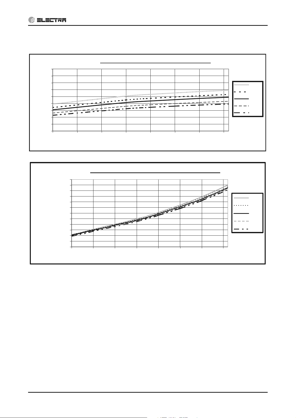
5.7 Pressure Correction Factor for Tubing Length
5.7.1 Cooling
Pressure vs Tubing Lenght (COOLING)
1.02
1.00
0.98
0.96
0.94
0.92
0.90
Suction Pressure Ratio
0.88
0.86
Cooling Suction Pressure
5 10152025303540455055606570
5.7.2 Heating
Cooling Discharge Pressure
Total Tubing Length [m]
Pressure vs Tubing Lenght (HEATING)
1.02
1.00
0.98
0.96
0.94
0.92
0.90
Discharge Pressure Ratio
0.88
0.86
1.02
1.01
1.00
0.99
0.98
0.97
0.96
Suction Pressure Ratio
0.95
0.94
5 10152025303540455055606570
Heating Suction Pressure
Heating Discharge Pressure
Total Tubing Lengtht [m]
1.02
1.01
1.00
0.99
0.98
0.97
0.96
Discharge Pressure Ratio
0.95
0.94
5-22
SM OU12HP 2-E.2 GB
Page 38

PERFORMANCE DATA & PRESSURE CURVES
CONTENTS
5.8 Calculation Example
Outdoor Unit OU12 5HP DCI
Indoor Unit DNG 125 DCI
Operation Mode Cooling Mode
Conditions Indoor 22qCDB/15qWB
Conditions Oudoor 30qCDB
Tubing length 50m
Cooling Capacity calculation:
Total Cooling Capacity (TC) [KW] = Capacity in conditions table x F
Cooling Capacity in table [KW] Tubing Length Factor (FT) Corrected Capacity [KW]
T
11.5 0.85 TC
Cooling Pressure calculation:
Pressure [KPa(g)] = Nominal Pressure (at 7.5m) x F
Nominal Pressure [KPa(g)] Tubing Length Factor (FT) Corrected Pressure [KPa(g)]
Discharge 2500 0.99 Pd= 2500 x 0.99 = 2475
Suction 800 0.925 Ps= 800 x 0.925 = 740
= 11.5x0.85=9.775
T
SM OU12HP 2-E.2 GB
5-23
Page 39

6. AIRFLOW CURVES
CONTENTS
6.1 Model: DNG 100 DCI
Air Flow vs. External Static Pressure
140
130
]aP[ erusserP citatS lanretxE
120
110
100
90
80
70
60
50
40
30
20
10
0
1,000 1,200 1,400 1,600 1,800 2,000 2,200 2,400
AIRFLOW CURVES
Nominal System Curve
Max Sy st em Cur ve
Medium Speed
Low Speed
High Speed
Operating Range
Perf ormance test
point at 37 Pa
Air Flow [m3/h]
6.2 Model: DNG 125 DCI
Air Flow vs. External Static Pressure
140
130
]aP[ erusserP citatS lanretxE
120
110
100
90
80
70
60
50
40
30
20
10
0
1,000 1,200 1,400 1,600 1,800 2,000 2,200 2,400
Nomina l Sy st em Cur ve
Max Sy st e m Cu r v e
Medium S p ee d
Low Speed
Hig h Spe ed
Operating Range
Perf ormance test
point at 50 Pa
Air Flow [m3/h]
SM OU12HP 2-E.2 GB
6-1
Page 40

AIRFLOW CURVES
CONTENTS
6.3 Model: EMD 100 DCI
Air Flow vs. External Static Pressure
Nominal System Cur v e
140
130
120
External Static Pressure [Pa]
110
100
90
80
70
60
50
40
30
20
10
0
800 1,000 1,200 1,400 1,600 1,800 2,000 2,200
Air Flow [m /h]
3
Max System Cu r v e
Medi um Speed
Low Speed
Hig h Speed
Operating Range
Performance test
point at 37 Pa
6.4 Model: EMD 125 DCI
Air Flow vs. External Static Pressure
140
130
120
110
100
90
80
70
60
50
40
30
External Static Pressure [Pa]
20
10
0
1,000 1,200 1,400 1,600 1,800 2,000 2,200 2,400 2,600 2,800
Air Flow [m /h]
Nominal System Cur v e
Max System Cu r v e
Medium Speed
Low Speed
High Speed
Operating Range
Performance test
point at 50 Pa
3
6-2
SM OU12HP 2-E.2 GB
Page 41

6.5 Model: CD 140 DCI
CONTENTS
AIRFLOW CURVES
6.6 DNG / EMD / CD UNITS RANGE AIR FLOW CORRECTION
FACTORS
* Permissible Air flow Rate - according to model Air Flow Curves
(at nominal rating conditions — Test mode).
Air Flow Rate [% of nominal]
60% 70% 80% 90% 100%
0.88 0.91 0.94 0.97 1
Cooling
Heating
TC
SC 0.78 0.84 0.89 0.95 1
PI 0.95 0.97 0.98 0.99 1
PI 1.07 1.05 1.03 1.02 1
TC 0.90 0.92 0.95 0.97 1
SM OU12HP 2-E.2 GB
6-3
Page 42

SOUND LEVEL CHARACTERISTICS
CONTENTS
7. SOUND LEVEL CHARACTERISTICS
7.1 Indoor Units Test Scheme
Figure 1
7.2 Sound Pressure Level Spectrum (Measured as Figure 1)
DNG 100 DNG 125
NC-70
NC-60
NC-50
NC-40
NC-30
APPROXIMATE
THRESHOLD OF
HEARING FOR
CONTINUOUS
NOISE
OCTAVE BAND SOUND PRESSURE LEVEL, dB re 0.002 MICRO BAR
APPROXIMATE
THRESHOLD OF
HEARING FOR
CONTINUOUS
NOISE
NC-20
OCTAVE BAND SOUND PRESSURE LEVEL, dB re 0.002 MICRO BAR
NC-70
NC-60
NC-50
NC-40
NC-30
NC-20
FAN SPEED LINE
SM OU12HP 2-E.2 GB
HI
ME
LO
BAND CENTER FREQUENCIES, Hz
BAND CENTER FREQUENCIES, Hz
7-1
Page 43

SOUND LEVEL CHARACTERISTICS
CONTENTS
EMD 100 EMD 125
OCTAVE BAND SOUND PRESSURE LEVEL, dB re 0.002 MICRO BAR
APPROXIMATE
THRESHOLD OF
HEARING FOR
CONTINUOUS
NOISE
BAND CENTER FREQUENCIES, Hz
CD 140
NC-70
NC-60
NC-50
NC-40
NC-30
NC-20
OCTAVE BAND SOUND PRESSURE LEVEL, dB re 0.002 MICRO BAR
APPROXIMATE
THRESHOLD OF
HEARING FOR
CONTINUOUS
NOISE
NC-70
NC-60
NC-50
NC-40
NC-30
NC-20
BAND CENTER FREQUENCIES, Hz
APPROXIMATE
THRESHOLD OF
OCTAVE BAND SOUND PRESSURE LEVEL , dB re 0.002 MICRO BAR
HEARING FOR
CONTINUOUS
NOISE
BAND CENTER FREQUENCIES, Hz
FAN SPEED LINE
HI
ME
LO
NC-70
NC-60
NC-50
NC-40
NC-30
NC-20
7-2
SM OU12HP 2-E.2 GB
Page 44

7.3 Outdoor Units
CONTENTS
SOUND LEVEL CHARACTERISTICS
1 m
1 m
Figure 2
7.4 Sound Pressure Level Spectrum (
OU12 4HP DCI Cooling OU12 4HP DCI Heating
Measured as Figure 2)
OU12 5HP DCI Cooling OU12 5HP DCI Heating
SM OU12HP 2-E.2 GB
7-3
Page 45

SOUND LEVEL CHARACTERISTICS
CONTENTS
OU12 6HP DCI Cooling OU12 6HP DCI Heating
7-4
SM OU12HP 2-E.2 GB
Page 46

ELECTRICAL DATA
CONTENTS
8. ELECTRICAL DATA
8.1 Single Phase Units
MODEL OU12 4PH DCI OU12 5-6PH DCI
Power Supply 1PH – 230V – 50 Hz
Connected to
(a)
Max Current 23A 5A 28A 5A
Inrush Current
Starting Current
(c)
(d)
Circuit Breaker 25A 10A 32A 10A
Outdoor Indoor Outdoor Indoor
30A
10A
Power Supply Wiring
No. X Cross Section
Interconnecting Cable
No. X Cross Section
(b)
3 X 4.0 mm
3 X 1.5 mm2 +
2 X 0.75 mm
(Communications)
2
3 X 1.5 mm
2
2 X 0.75 mm
(Communications)
2
3 X 6.0 mm23 X 1.5 mm
2
3 X 1.5 mm
2
2 X 0.75 mm
(Communications)
+
2
(Communications)
2 X 0.75 mm
2
2
(a) Power supply can be connected in both ways:
To outdoor unit to supply both outdoor and indoor unit.
To outdoor unit and to Indoor unit separately.
(b) Communication wires must be separated from the power wires and should be shielded type,
earth connectedat both ends.
(c) Inrush current is the current when power is up (charging the DC capacitors at outdoor unit
controller).
(d) Starting current is the current peak when starting the compressor.
NOTE:
Power wiring cord should comply with local lows and electrical regulations requirements.
SM OU12HP 2-E.2 GB
8-1
Page 47

9. WIRING DIAGRAMS
CONTENTS
9.1 Indoor Unit: DNG 100, DNG 125 DCI
WIRING DIAGRAMS
SM OU12HP 2-E.2 GB
ATTENTION! FOR OUTDOOR UNIT ELECTRICAL WIRING REFER TO OUTDOOR UNIT DIAGRAM
CAT No.: 473503/02
9-1
Page 48

WIRING DIAGRAMS
CONTENTS
9.2 Indoor Unit: EMD 100, EMD 125 DCI
9-2
ATTENTION! FOR OUTDOOR UNIT ELECTRICAL WIRING REFER TO OUTDOOR UNIT DIAGRAM
CAT No.: 473503/02
SM OU12HP 2-E.2 GB
Page 49

9.3 Indoor Units: CD 140 DCI
CONTENTS
WIRING DIAGRAMS
SM OU12HP 2-E.2 GB
9-3
Page 50

WIRING DIAGRAMS
CONTENTS
9.4 Outdoor Units: OU12 4-5HP DCI
9.5 Outdoor Units: OU12 6HP DCI
9-4
SM OU12HP 2-E.2 GB
Page 51

9.6 1PH UNITS POWER SUPPLY TO OUTDOOR
CONTENTS
(10.0, 12.5 Kw units)
WIRING DIAGRAMS
Indoor Unit1.
Power Supply Cable2.
Main Power Breaker3.
Outdoor Unit4.
Interconnecting cable (2x0.75mm5.
Power Interconnecting Cable (3x1.5mm6.
2
)**
2
)
Wireless remote Control7.
Display Unit8.
Display Connector9.
Power Breaker (*by installer)10.
Control Cable**11.
Sensor Wire with connector12.
Room Temperature Sensor13.
* The power breaker must be of type that disconnects all poles with 3 mm contact
opening.
** Use shielded cable and connect the shield to earth point
SM OU12HP 2-E.2 GB
9-5
Page 52

WIRING DIAGRAMS
CONTENTS
9.7 1PH UNITS POWER SUPPLY TO OUTDOOR and INDOOR UNIT
SEPERATELY
(10.0, 12.5 Kw units)
1. Indoor Unit
2. Power Supply Cable
3. Main Power Breaker
4. Outdoor Unit
5. Interconnecting cable (2x0.75mm2)*
6. Wireless remote Control
7. Display Unit
8. Display Connector
9. Control Cable*
10. Sensor Wire with connector
11. Room Temperature Sensor
* Use shielded cable and connect the shield to earth point.
9-6
SM OU12HP 2-E.2 GB
Page 53

REFRIGERATION DIAGRAMS
EEV
EEV
EEV
CONTENTS
10. REFRIGERATION DIAGRAMS
10.1 Heat Pump Models
10.1.1 DNG 100 / 125 DCI, EMD 100 / 125 DCI, CD 140 DCI
Cooling mode
Heating mode
SM OU12HP 2-E.2 GB
10-1
Page 54

11. TUBING CONNECTIONS
CONTENTS
TUBING CONNECTIONS
TUBE (Inch)
¼” ” ½” ” ¾”
TORQUE (Nm)
Flare Nuts
Valve Cap
Service Port Cap
1. Valve Protection Cap-end
2. Refrigerant Valve Port (use Allen wrench to open/close)
3. Valve Protection Cap
4. Refrigerant Valve
5. Service Port Cap
6. Flare Nut
7. Unit Back Side
8. Copper Tube
15-18 40-45 60-65 70-75 80-85
13-20 13-20 18-25 18-25 40-50
11-13 11-13 11-13 11-13 11-13
SM OU12HP 2-E.2 GB
11-1
Page 55

12. CONTROL SYSTEM
CONTENTS
12.1 Abbreviations
Abbreviation Definition
A/C Air Conditioner
BMS Building Management System
CCR Compressor Current
CCH Crankcase Heater
COMP Compressor
CTT Compressor Top Temperature sensor
DCI DC Inverter
E²PROM, EEP Erase Enable Programmable Read Only Memory
EEV Electronic Expansion Valve
HE Heating Element
HMI Human Machine Interface
HST Heat Sink Temperature sensor
Hz Hertz (1/sec) – electrical frequency
ICT Indoor Coil Temperature (RT2) sensor
IDU Indoor Unit
IFAN Indoor Fan
M2L Mega Tool (Monitoring SW)
MCU Micro Controller Unit
NA Not Applicable
OAT Outdoor Air Temperature sensor
OCT ODU Coil Temperature sensor
OMT Outdoor middle coil temperature
ODU Outdoor Unit
OFAN Outdoor Fan
PFC Power Factor Corrector
RAC Residential A/C
RC Reverse Cycle (Heat Pump)
RPS Rounds per second (mechanical speed)
RV Reverse Valve
SB,STBY Stand By
SH Superheat
SUCT/SCT Compressor Suction Temperature sensor
S/W Software
TBD To Be Defined
TEMP Temperature
TMR Timer
CONTROL SYSTEM
SM OU12HP 2-E.2 GB
12-1
Page 56

CONTROL SYSTEM
CONTENTS
12.2 Product Overview
12.2.1 Block Diagram
230VAC
IDU Controller
IFAN
Control
Inputs R/C
Dry
contacts
Line Filter
Inrush Control
(4-5HP Only)
Inrush
Control
IDU
Communication
Temp.
Inputs
Compressor
Driver
Driver
Control
ODU Controller
Display
230V
Outputs
EEV
Output
OFAN
Control
OFAN
Control
Dry
contact
M
Speed
HST
AC Current
DC Current
M
M
M
RAT
ICT
Overflow
Power Lines
Low Voltage
RC
RCW
PBMS
12.2.2 Compressor
DC brush less and sensor less motor inverter driven compressor.
12.2.3 Compressor Drive
DC inverter module to drive compressor.
12.2.4 Outdoor Fan
DC brush less motor.
PD
OAT
CTT
OMT
OCT
RV
BH
CCH
EEV
SB
Night
Power Shading
Alarm
HPS
LPS (6HP Only)
12-2
SM OU12HP 2-E.2 GB
Page 57

CONTROL SYSTEM
CONTENTS
12.2.5 RV
Reverse Valve set the direction of refrigerant flow in the system, thus setting the operation
mode for cooling or heating.
When the solenoid is powered, system will work in heat mode.
12.2.6 EEV
Expansion valve operated by step motor which controls the size of the orifice.
12.2.7 HMI
Consists of Four “7-Segments” + four Push buttons for display, monitoring and setup
features.
12.2.8 Dry Contacts
Dry contacts are used to interface the system with an external building management system
(BMS).
12.2.8.1 ODU Dry Contacts
• Night input. Switches the system to night mode when closed. During night mode, the
outdoor unit speed will be reduced in order to reduce the system noise level.
• SB input. System will be turned to Stand-by when the contact is closed.
• Power Shedding input. Limits the maximum power consumption when closed.
• Alarm output indicates a failure in the system.
Alarm output will be activated when there in the following ODU Faults/Protections
1 to 11, 13 to 20, 22 to 26, 28 to 29.
Alarm output will be OFF when the Fault/Protection is cleared.
12.2.8.2 IDU Dry Contacts
Presence detecter input.
12.2.9 Temperature Sensors
CTT – Compressor Top Temperature
OAT – Outdoor Air Temperature
OCT – Outdoor Coil (heat exchanger inlet) Temperature
OMT – Outdoor Coil (heat exchanger) Temperature
HST – Heat Sink Temperature
ICT – Indoor Coil (heat exchanger) Temperature
RAT – Return Air Temperature (Indoor Unit)
SM OU12HP 2-E.2 GB
12-3
Page 58

CONTROL SYSTEM
CONTENTS
12.2.10 Base Heater
Heating element designed to melt any ice that is accumulated on the outdoor unit base during
low heating operation.
12.2.11 Cranck case Heater
Heating element designed to heat up the compressor oil cranck case during low heating
operation.
12.2.12 Internal coil heater
Only exists in 6HP unit. The compressor is equiped with built-in heating coils designed to
heatup the compressor oil cranck case during low heating operation.
12.3 General Operating Rules
12.3.1 Communication with Indoor Unit
12.3.1.1 Communication Failures Definition
12.3.1.1.1 ‘Bad Communication’ fault
The system keeps a balance of a good/bad communication packet ratio. When the ratio
becomes high the system enters ‘Bad Communication’ fault. The system recovers from that
fault when the ratio reduced below the threshold.
When in ‘Bad Communication’ fault, system continues its normal operation and fault code is
shown in diagnostics.
12.3.1.1.2 ‘No Communication’ fault
If no legal transmission or no message received for 30 seconds, system enters ‘No
Communication’ fault.
When in ‘No Communication’ fault, the fault code will be shown in diagnostics. In this case,
the system will force the compressor to off.
The system will recover from ‘No Communication’ fault when counter is below 10 and legal
massage is received
12.3.2 Temperature Measurements
12.3.2.1 Thermistor failures definition
Thermistor Thermistor is Disconnected Thermistor is Shorted
OCT Temp < -35 °C Temp > 75 °C
OAT Temp < -30 °C Temp > 75 °C
CTT Temp < -30 °C Temp > 130 °C
OMT Temp < -30 °C Temp > 75 °C
ICT Temp < -30 °C Temp > 75 °C
RAT Temp < -30 °C Temp > 75 °C
12.3.2.2 System responses for different thermistor failure
Thermistor Default value System Reaction
COOL HEAT
OCT 1°C 1°C
OAT 43°C 6°C
CTT 43°C 43°C Forced compressor to OFF
HST 75°C 75°C
OMT 43°C 43°C Replaced by OCT
ICT 43°C 43°C
RAT SPT+4°C SPT-4°C
(1)
(1)
12-4
Notes:
(1) Whenever both OCT and OMT are faulty the compressor will be forced to OFF.
SM OU12HP 2-E.2 GB
Page 59

(2) Thermistor is defined as faulty (shorted/disconnected) if it’s faulty for more than 10
CONTENTS
seconds continuously. During this time, the system uses the last valid temperature.
12.4 Indoor Unit Control
12.4.1 Indoor Fan Control
When user sets the indoor fan speed to a fixed speed (Low/ Medium/ High), unit will operate
constantly at set speed.
When Auto Fan is selected, indoor fan will operate in all speeds according to the cool/heat
load.
12.4.2 Load calculation
LOAD is calculated according to the difference between actual room temperature and user set
point temperature by PI control.
In high/ medium/ low indoor fan user setting, unit will operate fan in selected speed.
In AutoFan user setting, fan speed will be adjusted automatically according to the calculated
LOAD.
12.4.3 Heat Mode
12.4.3.1 Temperature Compensation
CONTROL SYSTEM
A compensation value of 2-4 degrees is reduced from room temperature reading (except
when in I-Feel mode), to compensate for temperature difference between high and low areas
in the heated room, and for coil heat radiation on room thermistor.
The temperature compensation can be enabled/disabled by closing/opening J2 on the indoor
unit controller.
12.4.3.2 Indoor Fan Control in Heat Mode
When in heat mode, including protections and except Deicing, and when the conditions
in the table below are fulfilled, IFAN will be working according to the graph below.
SM OU12HP 2-E.2 GB
12-5
Page 60

CONTROL SYSTEM
CONTENTS
12.4.4 Auto Cool/Heat Mode
When in auto cool heat mode unit will automatically select between cool and heat mode
according to the difference between actual room temperature and user set point temperature
(T).
Unit will switch from cool to heat when compressor is off for 3 minutes, and T < -3.
Unit will switch from heat to cool when compressor is off for 5 minutes, and T < -3.
12.4.5 Dry Mode
As long as room temperature is higher then the set point, indoor fan will work in low speed and
compressor will work between 0 and maximum frequency in cooling.
When the room temperature is lower than the set point, compressor will be switched OFF and
indoor fan will cycle 3 minutes OFF, 1 minute ON.
12.4.6 Heating Element Control
Heating element can be turn on if high LOAD is more then 80% and Indoor Coil temperature
is less then 45qC.
The heating element will be off when LOAD is less then 50% OR if Indoor Coil temperature is
more then 50qC.
12.4.7 Indoor Unit Dry Contact
“Presence Detector” feature in the indoor unit is done for cases that external SB (Stand-By) is
required via a presence detector sensor or others such as window closed detector, etc.
The dry contact can be set to operate if the contacts are shorted as follows:
Function Contact = Open Contact = Short
Presence Detector Connection No Action – normal operation (Default) Forced to STBY
Notes:
o When the A/C is forced to STBY mode, all R/C commands are ignored, and the operation LED
blinks with 1 seconds cycle time.
o Any change in the Presence Detector state during the first 6 sec after the system reset is
ignored.
12.4.8 Operating the Unit from the Mode Button
Forced operation allows to start, stop and operate in Cooling or Heating, in pre-set temperature
according to the following table:
Forced operation Mode Pre-set Temperature
Cooling 20
Heating 28
0
C
0
C
12.4.9 On Unit Controls and Indicators
12-6
Indications during OFF, Fan, Cool, Heat, Dry, and Auto modes are shown below. For operation
in other modes, check the relevant paragraphs.
SM OU12HP 2-E.2 GB
Page 61

CONTROL SYSTEM
CONTENTS
STANDBY
INDICATOR
OPERATE
INDICATOR
TIMER INDICATOR
COOLING
INDICATOR
HEATING
INDICATOR
Mode SWITCH
(COOL/HEAT/OFF)
Lights up when the Air Conditioner is connected to power and is ready for operation
1. Lights up during operation.
2. Blinks for 300 msec to announce that a R/C infrared signal has been received
and stored.
3. Blinks continuously during protections (according to the relevant spec section).
Lights up during Timer and Sleep operation.
Lights up when system is switched to Cool Mode by using the Mode Switch on the
unit.
Lights up when system is switched to Heat Mode by using the Mode Switch on the
unit.
Every short pressing , the next operation mode is selected, in this order : SB
Cool Mode Heat Mode SB …
In long pressing system enters diagnostic mode.
12.5 Run Mode
Run mode is the default operation mode of the system. This is the standard operation mode that
is active in field application (at customer site).
System can go from run mode to other operation modes through keyboard or serial ports.
12.5.1 Mode Setting
Mode defines the ODU operation mode. There are three possible operation modes:
1. STBY – standby mode
2. COOL - the unit operating at cooling cycle
3. HEAT - the unit operating at heat pump cycle
SB mode can be set also by dry-contact.
12.5.1.1 ODU Protections
There are 4 ODU protections:
x Compressor overheating
x Heat sink overheating
x AC over current
x DC Over curren – not in 6HP unit
12.5.2 Compressor Speed Control
12.5.2.1 Compressor Min On/Off time
Compressor minimum OFF time is 3 minutes except during Deicing protection.
Compressor minimum ON time is 3 minutes, minimum ON time is ignored during protections,
and when unit is turned to STBY.
12.5.2.2 Compressor Startup
When started, compressor speed reaches 40 RPS and will not go below that during the first 5
minutes of compressor operation except when compressor forced OFF.
12.5.2.3 Compressor start up fail
If the compressor does not succeed to complete the startup procedure, it will report a compressorlock fault code.
It than retries the startup procedure for 3 times on every 10 seconds and enter a 3 minutes wait
condition before starting the next compressor startup sequence.
SM OU12HP 2-E.2 GB
12-7
Page 62

CONTROL SYSTEM
CONTENTS
12.5.2.4 Compressor operation while OFAN Error
In case an OFAN error a cured for 10 continues seconds and the compressor is on, the compressor
will be set to OFF until OFAN error will recover.
12.5.2.5 Maximum allowed speed limitation
For cool mode:
MaxFreqH
MaxFreqAsOATC
OATLimitC
OAT
For Heat mode:
MaxFreqH
MaxFreqHMaxFreqC
MaxFreqAsOAT1H
MaxFreqAsOAT2H
2 Degree2 Degree
OATLimit1H
2 Degree
OATLimit2H
Note: If OAT is faulty, there will be no limits.
12.5.2.6 Speed Change Limitations
When rising or lowering speed within the allowed operating range, the acceleration or deceleration
will be 1 RPS/sec.
12.5.2.7 Compressor Speed calculation
During normal operation (excluding protections) the compressor target speed is set according to
the NLOAD number received from the indoor unit and CompFac. CompFac is an indoor-outdoor
matching parameter, once it is 0, the compressor will be forced off, if it is number between 0.01
to1, the compressor target frequency is set by the following table.
OAT
NLOAD Target Speed [Hz]
<10 0
10 MinFreqC in cool OR MinFreqH in heat mode
11– 126 NLOAD*CompFac
127 MaxFreqC in cool OR MaxFreqH in heat mode
12.5.2.8 Speed Step Limitations
The compressor speed have some step limitations which it will not go above them for few minuits
after startup.
12.5.2.9 Compressor shutdown Procedure
There are 2 procedures for compressor shutdown:
1. Immediate shutdown – compressor is stopped on the spot.
2. Gradual shutdown – compressor speed is reduced gradually to the minimum speed by
NormAccel Hz/sec and then stops.
12-8
SM OU12HP 2-E.2 GB
Page 63

CONTROL SYSTEM
CONTENTS
# Shutdown Reason
1 IDU NLOAD=0 (or IDU protections) Gradual Minimum On time is kept.
2 IDU Shutdown (idle) Immediate
3 Deicing Immediate
4 ODU Protections Gradual
5 Sensor faulty (CTT or OCT+OMT) Immediate
6 HPS protection Immediate
7 LPS protection Gradual (Only in 6HP units)
Shutdown
procedure
12.5.3 EEV Control
12.5.3.1 EEV General Rules
The EEV is controlled to keep the discharge superheat temperature within preset control
values.
12.5.3.2 EEV initialization procedure
After power up the EEV performs initialization procedure while it closed completly and reopened
to predefind position. During initialization, the compressor is forced to off.
12.5.3.3 Balance time
During the first minutes after SB the correction is not calculated. After that the correction value is
updated every EEVCVTConst seconds.
12.5.3.4 Operation Range
The EEV operation range is defined according to the operation mode as following
ODU Mode Normal operation Notes
SB 450
COOL 60 to 480
HEAT 60 to 480
12.5.3.5 EEV initial value determination (EEVOL)
The EEV initial value (open loop) is determined according to the operation mode, the actual
frequency and ODU model. The values are determined according to the “EEV
Table”.
12.5.3.6 EEV opening determination in normal run mode
The target EEV value is the sum of open loop value (OL) and a result of the accumulative
correction values (CV). The EEV corrections are calculated every EEVCVTConst seconds.
¦
EEVEEVEEV
May change
according to model
CVOL
Parameters
OL
12.5.4 Outdoor Fan Speed Control
12.5.4.1 Speed Definition
The outdoor fans can work in 16 speed states controlled by OMT sensor in cool mode and ICT
sensor in heat mode in ralation to outdoor conditions.
SM OU12HP 2-E.2 GB
12-9
Page 64

CONTROL SYSTEM
CONTENTS
12.5.4.2 General Rules
The fans will be off when the compressor is off unless HST>55 or faulty and than
OFAN_up will remain ON.
Min time for speed change between speed states is 60 seconds.
The fan speed is also related to protections.
Whenever OFAN fault occurs the compressor will be stopped.
12.5.4.3 Night mode
During night mode, the OFAN and the compressor will be limited to lower speeds (Cool model
only).
12.5.5 RV State Setting
During heat mode (except during Deicing) RV is ON.
During cool/SB mode RV is OFF.
RV status will be changed only if COMP is OFF for 3 minutes or more.
12.5.6 Base Heater Setting
The base heater will be working only when RV is “ON” according to the following graph:
Base
Heater
OFF
ON
0
2
OAT
When OAT is faulty the base heater will be “ON” continuously in HEAT mode.
12.5.7 Crank case heater Operation
The crank case heater operates only when compressor is off and according to CTT as
following:
OFF
ON
-5 0
CTT
12.5.8 Compressor internal heating coil Operation
Only in 6HP unit.
The crank case heater operates only when compressor is off and according to CTT and OAT.
12-10
SM OU12HP 2-E.2 GB
Page 65

CONTROL SYSTEM
CONTENTS
12.5.9 Thermodynamic Protections
12.5.9.1 Protection level definition
Five protection levels are defined:
Normal – No protection status.
Stop-Rise (SR) – Compressor not allowed raise speed.
D1 - Compressor speed reduced.
D2 - Compressor speed reduced rapidly.
Stop-Compressor (SC) – Compressor stops.
12.5.9.2 IDU Protections
ICT Value ICT Trend
Indoor Coil
Defrost
Protection
ICT < -2 ICT > 62 SC SC SC SC SC
-2 ICT < 0 60 < ICT 62 D1 D1 D2 D2 D2
0 ICT < 2 55 < ICT 60 SR SR D1 D2 D2
2 ICT < 4 53 < ICT 55 SR SR SR D1 D2
4 ICT < 6 51 < ICT 53 Normal Normal SR SR D1
6 ICT < 8 49 < ICT 51 Normal Normal Normal SR SR
8 ICT ICT 49 Normal
Indoor Coil
Over Heating
Protection
Fast
Increasing
Increasing No change Decreasing
Fast
Decreasing
Operation logic of all protections is the same. The controlled input (CTT, HST, ACC, DCC) is
controlled by changing the protection level using the fuzzy logic algorithm according the input
level and the change rate.
The following table summarizes the basic levels of each protection:
Protection
level
Compressor Overheat
(CTT)
Compressor AC
Over current (ACC)
Compressor DC
Over current (DCC)
Heat Sink
(HST)
SC 95 25.0 22.0 90
D2 92 24.6 21.4 87
D1 90 24.2 20.8 85
SR 87 23.6 20.0 83
Normal 78
There are two sets of ACC values, the selection of the values are set according to the state of
the Power-Shed dry contact input.
Power-Shed input open ACC
Power-Shed input short PSOC
12.5.9.3 Total Protection Level Definition
The total protection level is defined by the higher level of protection received.
SM OU12HP 2-E.2 GB
12-11
Page 66

CONTROL SYSTEM
CONTENTS
12.5.10 Deicing
12.5.10.1 Deicing Starting Conditions
Deicing operation will start when either one of the following conditions exist:
Case 1: OCT is 8 degree lower then the ambiant temp and the minimum time from the last deicer
is passed.
Case 2: OCT is 12 degree lower then the ambiant temp and 30 minutes from the last deicer wa
passed.
OCT – Outdoor Coil Temperature
Deicing interval time when compressor is first started in heat mode, is 10 minutes if OCT < -2, and
is 40 minutes in other cases.
Deicing interval time is changed (increased/ decreased in 10 minutes steps) as a function of
deicing time.
In case one of the thermistors is bad the deicer will initiate in predefined intervals
Deicer may accure also when the unit switch to stanby and the OCT is 8 degree lower then
ambiant temperature.
12.5.10.2 Deicing Protection Procedure
12
Threshold
COMP
RV
OFAN
EEV
OCT
0
ON
HEAT
COOL
ON
OFF
EEVDeicerOpen
Any
T1 T2
T3 T3
T1
max. 12 minutes
DT
12.5.11 Condensate Water over Flow Protection
12-12
T1 = T2 = 36 seconds, T3 = 6 seconds
P1 P2 P3 P4
Each of the pins P1, P2, P3 can have two options:
1 – When it is shorted with P4
0 – When it is not shorted to P4
SM OU12HP 2-E.2 GB
Page 67

12.5.11.1 1 Level Logic
CONTENTS
P2 P3 Level
Don’t care 1 Normal
Don’t care 0 Overflow
CONTROL SYSTEM
Water Level
OPER
LED
NLOAD
PUMP
Overflow
Normal
ON
OFF
BLINK
ANY
0
ON
OFF
Overflow when
unit is ON
NLOAD is
forced to 0
8 min 8 min
Overflow when
unit is OFF
8 min
12.5.12 High/Low Pressure Protection
Whenever high or low pressure accures in the system which extend beind the system pre-defined
limits, the high and low pressure switchs turns on (short) and stops the compressor until these
limits are redrawn.
Fault code error 28 (HPS) or 29 (LPS) will be shown until compressor will resume operation.
12.6 Technician Test Mode
This test is aimed for the technicians to check the system under a preset compressor and outdoor
fan values while the expansion valves will function according to the normal running mode.
12.6.1 Entering technician mode
o This mode is entered through the outdoor unit using the HMI (refer to user interface
section).
o It can be selected either for cool or heat.
o Technician test is not possible to enter during deicer.
Exiting technician mode
Technician mode will be terminated either when:
o Escaping by the HMI (exit from the ttC or ttH menus)
o 60 minutes are passed from entering
SM OU12HP 2-E.2 GB
12-13
Page 68

CONTROL SYSTEM
CONTENTS
12.6.2 Technician mode procedure
x Indoor unit will enter technician test at high indoor fan speed.
x The outdoor unit will be working normally (according to the run mode control logic) except the
following changes:
o The dry contacts inputs will be ignored.
o Protections will be operative for stop compressor only.
o The compressor and the outdoor fan will be working in target preset values according to the
following table:
Technician Test
Unit
Compressor Speed
Cool Heat
4HP 54 64 800
5HP 71 75 800
6HP 55 63 800
OFAN
speed
12.7 User Interface
12.7.1 User interface description
o The user interface uses four 7-segments, and 4 keys.
o The 4 keys are:
- Scroll - used to scroll between options (up and down)
- Select - use to select an option
- Escape - Will go up one level in the menu
o The user interface concept is Tree menus.
Esc
Up
Select
Down
12-14
SM OU12HP 2-E.2 GB
Page 69

12.7.1.1 Status (Sub Menu)
CONTENTS
Status (StAt)
IDU
ICT
CONTROL SYSTEM
Operation Mode
Load
Family settings (FS) (In 6HP only)
ODU
Operation Mode
Value [qC]
Cool
Heat
Fan
Dry
NLoad Value
Family+model
Cool
Heat
SB
Deicing
OFAN UP
OFAN DN
RV
Speed
OAT
HST
OCT
CTT
Value [x10RPM)
Value [x10RPM]
Cool, Heat
Value [RPS]
Value [qC]
Value [qC]
Value [qC]
Value [qC]
SM OU12HP 2-E.2 GB
OMT
Value [qC]
12-15
Page 70

CONTROL SYSTEM
CONTENTS
Value [Amp]
In 6HP Only
EEV
Value
Primary Current
Value [Amp]
CompessorCurrent
Input current
Value [Amp]
Curent Release
Value [Amp]
Compressor On
Cnt
Value
Compressor On
Time (Cont)
Value
Model Name
Model Designation
12-16
SM OU12HP 2-E.2 GB
Page 71

12.7.2 Menus
CONTENTS
12.7.2.1 Main Menu
CONTROL SYSTEM
Mode (Cl/Ht/Sb)
Technician Test (tt)
Technician Test Cool (ttH)
Diagnostics (dia)
First Fault code
Second Fault code
Third Fault code
Forth Fault code
Fifth Fault code
Indoor Unit (IdU)
First Fault code
Second Fault code
Third Fault code
Forth Fault code
Technician Test Cool (ttC)
Outdoor Unit (OdU)
Heat
Fifth Fault code
Set Up (Set)
Indoor source
IDU power supply source (IdSU)
Max Current Limit (curL)
Power shade current limit (PSC)
Outdoor unit
Limit 30 A
Limit 27 A
Limit 23 A
Limit 18 A
Limit 14 A
50% of max current
60% of max current
70% of max current
80% of max current
SM OU12HP 2-E.2 GB
12-17
Page 72

CONTROL SYSTEM
CONTENTS
Parameters changing (Par)
Status (StAt)
ODU (OdU)
Change Parameters (CHG)
Restore Factory Parameters
(RST)
IDU (IdU)
Parameter No (Pxxx)
Notes:
1. The default presentation will be the mode of the unit (Cool/Heat/Stby).
2. In diagnostics menu:
x xx means failure code two numbers.
x Maximum 5 faults are presented for each unit (each IDUs/ODU). When no faults, a “----“ sign
will be shown.
x The active faults have higher priority for presentation than non active ones.
x Active errors will blink on/off each sec.
x Non active faults are presented according to their chronological order, starting from the latest
one.
x Whenever a new active fault occurs, it will be presented immediately.
3. The Parameters changing and Status menus (Technician menus) will be enabled to be presented
and navigated, only by pressing select + escape together for more than 5 seconds under the main
menu.
4. Exiting both ‘Parameters Changing’ and ‘Status’ menus and their sub-menus back to the main
menu is done only by either pressing escape for more than 5 seconds or after continuous 10
minutes out of any press.
5. Technician Test mode is exited after 60 minutes from entry.
6. All the menus, except technician menus- Parameter changing, Status, Technician Test and their
sub menus, are automatically exited to the main menu after 1 continuous minute out of any
press.
7. When Technician test cool or heat menus are selected (operative), it will be blinking constantly
until, this menu is escaped.
8. Pressing select and escape buttons together when in RST for more than 5 seconds will restore
only the parameters of the factory settings. Acknowledge for restored parameters will be indicated
by blinking RST for 3 seconds.
9. For the first 6 seconds after power is ON the display will show the current SW version. The display
will show each 4 letters of the SW version at the time.
Example – SW Version 361V1-A01:
Will be displayed as:
361u 1A01
3sec 3sec
12.7.2.2 Parameter Change (Sub Menu)
o The parameters names will be indicated by the sequence 001, 002,..,999.
o When a parameter is selected, the parameter’s stored value is presented-aligned to the
o Scrolling changes the presented value, incrementing or decrementing, but does not store
o Selecting a value, by pressing the selection key for 3 seconds, stores an updated value.
12-18
right.
the value.
SM OU12HP 2-E.2 GB
Page 73

12.7.2.3 Status (Sub Menu)
CONTENTS
CONTROL SYSTEM
Status (StAt)
IDU
ODU
ICT
Operation Mode
Load
Operation Mode
OFAN UP
OFAN DN
RV
Speed
OAT
HST
OCT
CTT
OMT
EEV
Value [qC]
Cool
Heat
Fan
Dry
NLoad Value
Cool
Heat
SB
Deicing
Value [x10RPM)
Value [x10RPM]
Cool, Heat
Value [RPS]
Value [qC]
Value [qC]
Value [qC]
Value [qC]
Value [qC]
Value
SM OU12HP 2-E.2 GB
12-19
Page 74

CONTROL SYSTEM
CONTENTS
Primary Current
Value [Amp]
CompessorCurrent
Value [Amp]
Notes:
x For the temperature display, when a thermistor is shorted or disconnected it shows FLT (FLt),
when it is disabled it shows DIS (dis).
x It’s possible to present a number between 999 and 99,999 by alternating between two
numbers (each number is presented for 1 second). The two numbers format is "xx, yyy".
x Pressing select + escape together for 5 seconds will reset the counter to 0.
x The compressor time is measured in hours.
12.8 Jumper (DIP Switch) Setting
12.8.1. Jumper Definition
0 = Open (Disconnected)
1 = Close (Shorted)
12.8.2. IDU Jumpers
12.8.2.1. Self test Jumper/DIP – J1
Position Status Description
0 Open (Disconnected) Normal Operation (Default)
1 Close (Shorted) Self Test enabled
12.8.2.2. Compensation Jumper/DIP – J2
Position Status Description
0 Open (Disconnected) Compensation deactivated
1 Close (Shorted) Compensation activated (Default)
12-20
SM OU12HP 2-E.2 GB
Page 75

12.8.2.3. Family selection Jumper/DIP – J3, J4, J5
CONTENTS
#
J3 J4 J5
Family Name
DNG 4-5HP 1 1 0
EMD 4-5HP 0 1 0
CD 6HP 1 0 1
12.8.2.4. Model selection Jumper/DIP – J7, J8
Model J7 J8
A – 4HP 0 0
B – 5HP 1 0
C – 6HP 0 1
12.8.2.5. Presence Detector/DIP – J9
CONTROL SYSTEM
Position Status Description
0 Open (Disconnected)
1 Close (Shorted) NA (Not to be used)
12.8.3. ODU Jumpers
12.8.3.1. Self test Jumper/DIP – J1
Position Status Description
0 Open (Disconnected) Normal Operation (Default)
1 Close (Shorted) Self Test enabled
Presence detector enabled (Default)
12.8.3.2. ODU Model Selection Jumper/DIP – J2, J3, J4, J5
SM OU12HP 2-E.2 GB
ODU Model J2 J3 J4 J5
M (DCI 100) ON OFF ON ON
N (DCI 125) OFF ON ON ON
O (DCI 140) ON ON ON ON
12-21
Page 76

CONTROL SYSTEM
CONTENTS
12.8.4. Dip-Switch Setting table
ODU
ODU 4HP
ON
OFF
12345678
ODU 5HP
ODU 6HP
DNG100
DNG125
EMD100
ON
OFF
ON
OFF
IDU
12345789
ON
OFF
ON
OFF
ON
OFF
EMD125
CD140
ON
OFF
ON
OFF
Note: in some cases where an external room thermostat kit is installed, the configuration of J2
in the indoor unit controller will be set to OFF.
12-22
SM OU12HP 2-E.2 GB
Page 77

12.9 System Parameters
CONTENTS
12.9.1 General Parameters for All Models
12.9.1.1 4-5HP
Name Default Value Units
MinOFFTime 3 minute
MinONTime 3 minute
HzDown1 3 Hz/min
HzDown2 10 Hz/min
DImin 30 minute
DImax 120 minute
TimeD 1 minute
DTmin 2 minute
DTmax 12 minute
DIT 10 minute
CTMRUP 15 minute
DIF 30 minute
TCT 10 second
HSTOH1 78 °C
HSTOH2 83 °C
HSTOH3 85 °C
HSTOH4 87 °C
HSTOH5 90 °C
HSTOHDelta1 -1 NA
HSTOHDelta2 1NA
EEVCVTConst 15 second
BalanceTime 1 minute
EEVInitOpen 300 step
DEICT1 60 second
DEICT2 36 second
DEICT3 6 second
EEVNormRate 33 ms/pulse
EEVHighRate 12 ms/pulse
EEVMaxOpen 500 step
DST 8°C
DSTF 12 °C
DeiceFreqChRV 0Hz
EEVDeiceTcnst 20 second
OFBlncTime 2 minute
OFTcnst 60 second
OFMinTimeReduce 60 second
CONTROL SYSTEM
SM OU12HP 2-E.2 GB
12-23
Page 78

CONTROL SYSTEM
CONTENTS
12.9.1.2 6HP
Name Default Value Units
MinOFFTime 3 minute
MinONTime 3 minute
HzDown1 3 Hz/min
HzDown2 10 Hz/min
DImin 30 minute
DImax 120 minute
TimeD 1 minute
DTmin 2 minute
DTmax 12 minute
DIT 10 minute
CTMRUP 15 minute
DIF 30 minute
TCT 10 second
HSTOH1 88 °C
HSTOH2 93 °C
HSTOH3 95 °C
HSTOH4 97 °C
HSTOH5 100 °C
HSTOHDelta1 -1 NA
HSTOHDelta2 1NA
EEVCVTConst 15 second
BalanceTime 1 minute
EEVInitOpen 300 step
DEICT1 60 second
DEICT2 36 second
DEICT3 6 second
EEVNormRate 33 ms/pulse
EEVHighRate 12 ms/pulse
EEVMaxOpen 500 step
DST 8°C
DSTF 12 °C
DeiceFreqChRV 0Hz
EEVDeiceTcnst 20 second
OFBlncTime 2 minute
OFTcnst 60 second
OFMinTimeReduce 60 second
12-24
SM OU12HP 2-E.2 GB
Page 79

12.9.2 ODU Model Dependent Parameters
CONTENTS
CONTROL SYSTEM
# Name
1.
2.
3.
4.
5.
6.
7.
8.
9.
10.
11.
12.
13.
14.
15.
16.
17.
18.
19.
20.
21.
22.
23.
24.
25.
26.
27.
28.
29.
30.
31.
32.
MinFreqC 25 25 20 Hz
MaxFreqC 75 85 70 Hz
MinFreqH 25 25 20 Hz
MaxFreqH 90 100 75 Hz
Step1Freq 40 40 40 Hz
Step2Freq 90 90 90 Hz
Step3Freq 120 120 120 Hz
NightRPM 60 60 60 *10RPM
CTTOH1 87 87 87 °C
CTTOH2 90 90 90 °C
CTTOH3 92 92 92 °C
CTTOH4 95 95 95 °C
ACCOC1 16.6 23.6 23.0 A
ACCOC2 17.2 24.2 23.8 A
ACCOC3 17.6 24.6 24.4 A
ACCOC4 18.0 25.0 25.0 A
DCCOC1 20.0 20.0 - A
DCCOC2 20.8 20.8 - A
DCCOC3 21.4 21.4 - A
DCCOC4 22.0 22.0 - A
EEVMinOperOpenC 60 60 60 step
EEVMaxOperOpenC 400 400 480 step
EEVMinOperOpenH 60 60 60 step
EEVMaxOperOpenH 480 480 480 step
OATLimitC 25 25 25 °C
OATLimit1H 4 4 4 °C
OATLimit2H 15 15 15 °C
MaxFreqAsOATC 70 70 60 Hz
MaxFreqAsOAT1H 90 90 80 Hz
MaxFreqAsOAT2H 60 60 60 Hz
NormAccel 1 1 1 Hz/s
NormDecel 1 1 1 Hz/s
M
Unit
DCI112NDCI140ODCI160
SM OU12HP 2-E.2 GB
33.
34.
35.
36.
OCTExitDeicer 12 12 12 °C
MaxDeicerTime 12 12 12 minute
DryContactDis 1 1 1 Byte
NightRPS 60 60 55 RPS
12-25
Page 80

CONTROL SYSTEM
CONTENTS
12.9.3 Indoor Units SW Parameters
Parameters defining the indoor fan speed as a function of Indoor Coil temperature in heat mode
(ICT):
12.9.3.1 Parameters for defrost protection:
ICTST Speed ICT to stop indoor fan 25
ICTVLSpeed ICT to go down to very low speed 28
ICTLSpeed ICT to start in very low speed 30
ICTHSpeed
ICTTSpeed ICT to enable Turbo fan speed 40
ICTDef1 ICT to go back to normal 8
ICTDef2 ICT to ‘stop rise’ when ICT decrease 6
ICTDef3 ICT to ‘stop rise’ when ICT is stable 4
ICTDef4 ICT to ‘Hz Down’ when ICT decrease 2
ICTDef5 ICT to ‘Hz Down’ when ICT is stable 0
ICTDef6 ICT to stop compressor -2
12.9.3.2 Parameters for indoor coil over heating protection:
ICT to start in increase speed from very
low
32
ICTOH1 ICT to go back to normal 49
ICTOH2 ICT to ‘stop rise’ when ICT increase 51
ICTOH3 ICT to ‘stop rise’ when ICT is stable 53
ICTOH4 ICT to ‘Hz Down’ when ICT increase 55
ICTOH5 ICT to ‘Hz Down’ when ICT is stable 60
ICTOH6 ICT to stop compressor 62
12-26
SM OU12HP 2-E.2 GB
Page 81

TROUBLESHOOTING
CONTENTS
13. TROUBLESHOOTING
13.1 Precaution, Advise and Notice Items
13.1.1 High voltage in Indoor and Outdoor unit electrical assembly
Open the Outdoor unit controller assembly only after one minute from power off.
Whole controller assembly, including the wires, connected to the Outdoor unit may have the
potential hazard voltage when power is on.
Touching the Outdoor unit controller assembly may cause an electrical shock.
Do not touch the naked lead wire and don’t insert finger, conductor or anything else into the
controller when power is on.
13.1.2 Charged Capacitors
Large capacity electrolytic capacitors are used in the outdoor unit controller and driver.
Charging voltage (380VDC) remains after power is down.
Discharging takes about one minute after turned off.
Touching the outdoor unit electrical assembly before discharging may cause an electrical
shock.
Measure the electrolytic capacitors voltage to be below 50VDC before further checking
electrical assembly parts.
13.1.3 Advisory Notes
When open the Outdoor unit electrical assembly, don’t touch the soldering pin by hand or by
any conductive material.
When connecting or disconnecting the connectors on the PCB, hold the whole housing, don’t
pull the wire.
WARNING!!!
¾When Power Up – the outdoor and indoor unit electrical assemblies, including the
wiring, are under HIGH VOLTAGE!!!
¾Never open the outdoor or indoor units before turning off ALL Power sources!!!
¾When turned off, the outdoor unit electrical assembly is still charged (400V)!!!
¾DC capacitors are discharging for about 1 Minute after power is OFF.
¾Touching the electrical before discharging may cause an electrical shock!!!
¾ For safe handling of the electrical assembly please refer to section 13.1 above.
SM OU12HP 2-E.2 GB
13-1
Page 82

TROUBLESHOOTING
CONTENTS
13.2 General System Failures and Corrective Actions
No.
Indoor unit
1.
2
3
4
SYMPTOM /
PROBLEM
Indoor unit power
supply indicator (Red
LED) does not light
up.
Fuse burned in
indoor unit controller
Indoor unit does not
respond to remote
control message
Indoor unit responds
to remote control
message but Operate
indicator (Green
LED) does not light
up
PROBABLE
CAUSE
No Power
supply
No supply from
outdoor
Miss-wiring
Loose
connection
Display and
display cable
If still not OK Check if fuse burnt
Short Circuit
between wires
Failure of Indoor
Unit Fan Motor
If still not OK Replace fuse
Remote control
message not
reached the
indoor unit
If still not OK
Problem with
display PCB
If still not OK Replace indoor Electronic Assembly (14.2.2)
Check supply voltage to main terminals L and N
with volt meter.
Check fuse at the connection wiring on outdoor
unit terminals (see Electrical Scheme 9.4)
Check all supply wiring to controller and
terminals according to wiring diagram
Check all power wiring connections
Check continuity of each wire of the display
wires/pins with Ohm meter
Check for any cuts or exposed supply wires or
miss-wiring
Check the motor and capacitor (13.5.19)
Check for any cuts or exposed wires
Check remote control batteries
Check continuity of each wire of the display
wires/pins with Ohm meter
Replace display box or indoor Electronic
Assembly (14.2.2, 14.2.3)
Replace display PCB (14.2.3).
CORRECTIVE ACTION
5
6
13-2
vIndoor fan does not
start (louvers are
opened and Green
LED is ON)
Indoor fan works
when unit is OFF,
and indoor fan speed
is not changed
by remote control
command.
Unit in heat
mode and coil is
still not warm
Failure of Indoor
Unit Fan Motor
Problem with
controller or
motor capacitor
If still not OK Replace indoor Electronic Assembly (14.2.2)
Controller
problem
Change to Cool or Fan mode
Check the motor and capacitor (13.5.19)
Check for any cuts or exposed wires
Change to high speed and Check power supply
to motor is higher than 220VAC
Replace indoor Electronic Assembly (14.2.2)
SM OU12HP 2-E.2 GB
Page 83

TROUBLESHOOTING
CONTENTS
No.
7
Outdoor unit
8
9
SYMPTOM /
PROBLEM
Water leakage from
indoor unit
Outdoor unit display
board and leds are
off
Compressor does not
start operation
PROBABLE
CAUSE
Indoor unit
drainage tube is
blocked
No power
supply
Miss-wiring
Loose
connection
Burnt fuse Check fuse on the main board (13.5.8)
If still not OK Replace main board (14.1.13)
One or some
components are
not operating
well
Electronics
control problem
or protection
PFC Chock coil Check the PFC Chock coil (13.5.6)
Driver failure
If still not OK Replace compressor (14.1.10)
Check and open drainage tube
Check supply voltage to main terminals L and N
with volt meter.
Check all supply wiring to controller and
terminals according to wiring diagram
Check all power wiring connections
Check for any fault code shown on display
board and act accordingly (13.4)
Check if fault code #11, 18, 19 or 26 is
shown on display board. If so, fix the problem
according to (13.5.5) or replace driver (14.1.15).
CORRECTIVE ACTION
SM OU12HP 2-E.2 GB
13-3
Page 84

TROUBLESHOOTING
CONTENTS
No.
10
SYMPTOM /
PROBLEM
Cooling capacity is
not sufficient
PROBABLE
CAUSE
Unit size not
match the load
Piping size
not matching
system
Refrigerant
leakage
Refrigerant
over-charge
Refrigerant clog
Electronics
control problem
or protection
Compressor
failure
Indoor coil block Clean filters and/or remove block or air by-pass
Indoor fan
malfunction
Overflow
Outdoor coil
block
Outdoor fan
malfunction
Indoor fan
malfuction
EEV malfunction Check EEV (13.5.12)
Thermistor(s)
malfunction
Check all according to above cooling problem (11)
Reverse valve Check reversing valve operation (13.5.11)
Check if the size chosen for the complete
room(s) load is enough or need bigger units
Check if piping is installed correctly and proper
diameter size and total length is according to
unit specifications
Check refrigeration system (13.3)
Check and repair clogging specially near the
EEV
Check for any fault code shown on display
board and act accordingly (13.4)
Check if fault code #11 or 26 is shown on
display board. If so, fix the problem according to
(13.5.10) or replace driver
Check the motor and capacitor (13.5.19)
Check if the overflow switch is ON. Replace
faulty switch or correct drain piping.
Remove block and/or avoid air by-pass
Check outdoor fan motors (13.5.9)
Check if the overflow switch is ON. Replace
faulty switch or correct drain piping.
Check if any of fault codes #1-10 is shown
on display board. Replace faulty thermistors
(14.1.11, 14.1.12)
CORRECTIVE ACTION
11
13-4
Heating capacity is
not sufficient
Deicing not
performed
well (during
low outdoors
temperatures)
Check OCT and OAT thermistors fault codes
(#1-2 and 7-8)
Check OCT thermistor if connected well to pipe
Check OAT thermistor if connected well
Check the thermistors operation (13.5.13)
SM OU12HP 2-E.2 GB
Page 85

TROUBLESHOOTING
CONTENTS
No.
12
13
14
SYMPTOM /
PROBLEM
Compressor is over
heated
Compressor stops
many times during
operation
Unit is cooling while
in heat mode
PROBABLE
CAUSE
Electronic
control
EEV problem Check EEV (13.5.12)
Refrigerant
leakage
Indoor coil block Clean filters and/or remove block
Indoor fan
malfunction
Outdoor coil
block
Outdoor fan
malfunction
Compressor
malfunction
Check all according to above problem (13)
HP Switch
LP Switch
RV problem Check RV operation (13.5.11)
IDU-ODU
communication
Check for any fault code shown on display
board and act accordingly (13.4)
Check refrigeration system (13.3)
Check indoor fan motor and capacitor (13.5.19)
Remove block and/or avoid air by-pass
Check outdoor fan motors (13.5.9)
Check the compressor (13.5.10)
Check if HPS fault code (#28) is accruing
frequently. If so, check the switch operation
(13.5.14)
Check if LPS fault code (#29) is accruing
frequently. If so, check the switch operation
(13.5.15)
Check the communication between outdoor and
indoor units (13.5.17)
CORRECTIVE ACTION
Compressor is
15
generating abnormal
noise
Freezing of outdoor
unit coil in heat mode
16
and outdoor unit base
is blocked with ice
The unit stop
17
suddenly during
operation
Indoor unit Indicator
18
leds may flicker
Phase order to
compressor is
wrong
Compressor
internal parts
wearing
Vibration
EMC
interference to
the A/C unit
Check compressor phase order
Replace compressor (14.1.10)
Check all piping connections
Check compressor rubbers are fixed well
Check all screws on unit metal chassis are
tightened
Check that no piping is in contact with each
other or with other parts.
Connect base heater
Check for EMC problems (13.5.20.1)
SM OU12HP 2-E.2 GB
13-5
Page 86

TROUBLESHOOTING
CONTENTS
No.
19.
20. All others
SYMPTOM /
PROBLEM
Other home
appliances operation
is faulty such as
noise appears in the
television picture,
or the picture is
distorted or static
occurs in the radio
sound
PROBABLE
CAUSE
EMC
interference by
the A/C unit
Specific
problems
of indoor or
outdoor units
CORRECTIVE ACTION
Check for EMC problems (13.5.20.2)
Check for any fault code shown on display
board and act accordingly (13.4)
13.3 Checking the refrigeration system
Checking system pressures and other thermodynamic measures should be done when system
is in technician Mode where the system operates as in fixed settings. The performance curves
given in this manual are given for unit performance in Technician mode when high indoor fan
speed is selected.
For entering technician mode see 12.6.
13.4 Troubleshooting by Diagnostics Codes
13.4.1 Fault Code for Outdoor Unit
If any fault exists in the system, its fault will be shown according to the following coding method.
The 5 last fault occurred in the system will be stored in the EEPROM.
If no fault exist in the system, no fault code will be displayed during normal operation mode.
STATUS LED is blinking 5 times in 5 seconds, and shut off for the next 5 seconds.
FAULT LED will blink during the same 5 seconds according to the following table
The LED coding method is as follow:
STBY STATUS FAULT
13-6
SM OU12HP 2-E.2 GB
Page 87

TROUBLESHOOTING
CONTENTS
No Problem 54321
1 OCT is disconnected 00001
2 OCT is shorted 00010
3 CTT is disconnected 00011
4 CTT is shorted 00100
5 HST is disconnected (when enabled) 00101
6 HST is shorted (when enabled) 00110
7 OAT is disconnected 00111
8 OAT is shorted 01000
9 OMT is disconnected 01001
10 OMT is shorted 01010
11 IPM Fault 01011
12 Bad EEPROM 01100
13 DC under voltage 01101
14 DC over voltage 01110
15 AC under voltage 01111
16 IDU/ODU Communication mismatch 10000
17 No Communication to IDU 10001
18 No Communication to Driver 10010
19 Current sensor Fault 10011
20 Heat sink Over Heating 10100
21 Deicing 10101
22 Compressor Over Heating 10110
23 Compressor Over Current 10111
24 OFAN_UP error 11000
25 OFAN_DN error 11001
26 Compressor Lock 11010
27 Bad Communication 11011
28 High pressure protection 11100
29 Low pressure protection 11101
30 Reserved 11110
31 Reserved 11111
1 - ON, 0 - OFF
Only one code is shown. Order of priority is lower to the higher number. Diagnostics is continuously
ON as long power is on.
SM OU12HP 2-E.2 GB
13-7
Page 88

TROUBLESHOOTING
CONTENTS
13.4.2 Outdoor unit diagnostics and corrective actions
No Fault Name Fault Description Corrective Action
1 OCT is disconnected
2 OCT is shorted
3 CTT is disconnected
4 CTT is shorted
HST is disconnected
5
(when enabled)
HST is shorted (when
6
enabled)
7 OAT is disconnected
8 OAT is shorted
9 OMT is disconnected
10 OMT is shorted
11 IPM Fault
Thermistor not connected
or damaged
Over current / IPM
malfunction
Check Thermistor (13.5.13)
Check no obstruction to electrical
box and outdoor coil air inlet.
Check if the inrush wiring is
connected and if the inrush circuitry
is operating well (13.5.4)
Check Compressor (13.5.10)
Check Driver (13.5.5)
Check Capacitors (13.5.7)
12 Bad EEPROM
13 DC under voltage
14 DC over voltage
15 AC under voltage
EEPROM parameters are
corrupted
DC voltage is lower than
limit
DC voltage exceeds its
high -
AC input voltage is lower
than limit
Reset the power. If problem still exist
replace PCB only when change is
required parameters
Check if input voltage lower than
limit (198VAC), if not and the
problem persists, replace driver.
If voltage is low, recommend the
customer to fix the power supply
Check driver (13.5.5)
Check DC capacitors (13.5.7)
Check if input voltage higher than
limit (253VAC), if not and the
problem persists, replace driver.
If voltage is high, shut off the power
and recommend the customer to fix
the power supply
Check if input voltage lower than
limit (198VAC), if not and the
problem persists, replace driver.
If voltage is low, recommend the
customer to fix the power supply
16
17
13-8
IDU/ODU
Communication
mismatch
No Communication to
IDU
Mismatch between IDU
and ODU models
IDU-ODU communication
Units are not designed to operate
together as system. Check and
replace the models installed.
Check communication between
indoor and outdoor units (13.5.17)
SM OU12HP 2-E.2 GB
Page 89

TROUBLESHOOTING
CONTENTS
No Fault Name Fault Description Corrective Action
No Communication to
18
Driver
19 Current sensor Fault Driver fault Replace Compressor Driver
Heat sink Over
20
Heating
21 Deicing During deicing procedure
Compressor Over
22
Heating
Compressor Over
23
Current
24 OFAN_UP error
25 OFAN_DN error
26 Compressor Lock
Driver fault
Compressor stopped due
to heat sink protection
Compressor stopped due
to over heat protection
Compressor stopped due
to over current protection
Outdoor fan(s) does not
rotate
Compressor does not
rotate
Check power supply to driver
Check driver communication
(13.5.16)
Check that the airflow around the
ODU is free and the fan is running
free
Check the screws connecting the
driver to heat sink are tighten
Check outdoor fan motors (13.5.9)
Normally no action is required
If the problem persists for more
than twice on each hour, check for
refrigerant leak and thermodynamic
operation (13.3)
Normally no action is required
If the problem persists for more
than twice on each hour, check for
refrigerant leak and thermodynamic
operation (13.3)
Check the EEV (13.5.12)
Check the Outdoor fans (13.5.9)
Check the Indoor fans (13.5.19)
Check the Compressor (13.5.10)
Check the CTT Thermistor (13.5.13)
Normally no action is required
If the problem persists for more
than twice on each hour, check
for refrigerant leak or clog and
thermodynamic operation (13.3)
Check the EEV (13.5.12)
Check the Outdoor fans (13.5.9)
Check the Indoor fans 13.5.19)
Check the Compressor (13.5.10)
Check no obstruction to outdoor unit
coil air path
Check OFAN motor (13.5.9)
Check if the inrush wiring is
connected and if the if the inrush
circuitry is operating well (13.5.4)
Check Compressor (13.5.10)
Check driver (13.5.5)
Check Zero-cross wiring from driver
to Line Filter (6HP Only)
27 Bad Communication Bad communication lines
SM OU12HP 2-E.2 GB
Check communication between
indoor and outdoor units (13.5.17)
13-9
Page 90

TROUBLESHOOTING
CONTENTS
No Fault Name Fault Description Corrective Action
Normally no action is required
If the problem persists for more
than twice on each hour, check for
High pressure
28
protection
Low pressure
29
protection
Compressor stopped due
to high pressure protection
Compressor stopped due
to low pressure protection
refrigerant clog.
Check the switch operation (13.5.14)
Check the EEV (13.5.12)
Check the Outdoor fans (13.5.9)
Check the Indoor fans (13.5.19)
Check the Compressor (13.5.10)
Normally no action is required
If the problem persists for more
than twice on each hour, check for
refrigerant leak.
Check the switch operation (13.5.15)
Check the EEV (13.5.12)
Check the Outdoor fans (13.5.9)
Check the Indoor fans (13.5.19)
Check the Compressor (13.5.10)
Check the CTT Thermistor (13.5.13)
13.4.3 Fault Code for Indoor unit
Note: Indoor unit diagnostics can be viewed by the outdoor unit display board (13.4).
The below procedure is for viewing the indoor unit codes via the indoor unit led display.
Pressing Mode button for more than 5 seconds will activate diagnostic mode by the acknowledgment
of 3 short beeps and lighting of COOL and HEAT LED’s.
When Indoor diagnostics is displayed, all four LED’s (STBY, Operate, Filter, TMR) are on.
Entering diagnostics in STBY mode allows only viewing of status (fault-display).
In diagnostic mode, system problems / information will be indicated by blinking of Heat & Cool
LED’s.
The coding method will be as follows:
Heat led will blink 5 times in 5 seconds, and then will be shut off for the next 5 seconds. Cool Led will
blink during the same 5 seconds according to the following table:
13-10
SM OU12HP 2-E.2 GB
Page 91

TROUBLESHOOTING
CONTENTS
No Fault Name 54321
1 RT-1 is disconnected
2 RT-1 is shorted
3 RT-2 is disconnected
4 RT-2 is shorted
… Reserved
7 Communication mismatch
8 No Communication
9 No Encoder
10 Reserved 01010
11 Outdoor Unit Fault 01011
… Reserved
17 Defrost protection 1
18 Deicing Protection 1
19 Outdoor Unit Protection 1
20 Indoor Coil HP Protection 1
21 Overflow Protection 1
… Reserved
24 EEPROM Not Updated 1 1
25 Bad EEPROM 1 1
26 Bad Communication 1 1
27 Using EEPROM data 1 1
28 Model A 1 1 1
29 Model B 1 1 1
30 Model C 1111
31 Model D 11111
1
1
11
1
1
111
1
1
1
1
1
1
11
1
1
1
11
1
1 - ON, 0 - OFF
Only one code is shown. Order of priority is lower to the higher number. Diagnostics is continuously
ON as long power is on.
13.4.4 Indoor unit diagnostics and corrective actions
No. Fault Probable Cause Corrective Action
Sensors not
1-4 Sensor failures
Communication
7
mismatch
8 No Communication
9 No Encoder
connected or
damaged
Mismatch between
IDU and ODU
models
IDU-ODU
communication
Indoor electronics or
motor
If still not ok
Check Thermistor (13.5.13)
Units are not designed to operate
together as system. Check and replace
the models installed.
Check communication between indoor
and outdoor units (13.5.17)
Check motor wiring, if ok, replace motor
replace Indoor electronic assembly
(14.2.2)
11 Outdoor Unit Fault
17-18 Protections Indication No action
SM OU12HP 2-E.2 GB
Outdoor controller
problem
Check for any fault code shown on
outdoor unit display board and act
accordingly (13.4)
13-11
Page 92

TROUBLESHOOTING
CONTENTS
No. Fault Probable Cause Corrective Action
Normally no action is required
If the problem persists for more than
twice on each hour, Check for any fault
code shown on outdoor unit display board
and act accordingly (13.4)
Check the EEV (13.5.12)
Check the Outdoor fans (13.5.9)
Check the Indoor fans (13.5.19)
Check the Compressor (13.5.10)
Check the CTT Thermistor (13.5.13)
Normally no action is required
If the problem persists for more than
twice on each hour, check for refrigerant
leak and thermodynamic operation (13.3)
Check the EEV (13.5.12)
Check the Outdoor fans (13.5.9)
Check the Indoor fans (13.5.19)
Check the Compressor (13.5.10)
Check the CTT Thermistor (13.5.13)
19
20
Outdoor Unit
Protection
Indoor Coil HP
Protection
Compressor stopped
due to outdoor unit
protection
Compressor stopped
due to high pressure
(heating) protection
21 Overflow Protection
24
25 Bad EEPROM
26 Bad Communication
27
28
29
30
EEPROM Not
Updated
Using EEPROM
data
IDU model
Compressor stopped
due to water level
overflow protection
System is using
ROM parameters
and not EEPROM
parameters
IDU-ODU
communication
No problem
Indoor unit model
connected is shown:
Model A - 4HP unit
Indoor unit model
connected is shown:
Model B - 5HP unit
Indoor unit model
connected is shown:
Model C - 6HP unit
Check the drainage tube for any clog.
Correct drain piping or float switch if
needed.
It is highly recommended to install a
siphon into the unit drainage point.
No action, unless special parameters are
required for unit operation.
No action, unless special parameters are
required for unit operation.
Check communication between indoor
and outdoor units (13.5.17)
No problem
31 Not applicable
13-12
SM OU12HP 2-E.2 GB
Page 93

TROUBLESHOOTING
CONTENTS
13.5 Procedures for checking Main Parts
13.5.1 Discharge DC Voltage
High voltage!!!
Wait for DC voltage to be discharged beforere touching any part of the driver to
avoid electric shock.
Check to ensure that DC voltage has reduced to below 50VDC, if not, keep
waiting until it does.
13.5.2 Checking Line Mains Voltage
Confirm that the Mains voltage is between 198 and 253 VAC. If Mains voltage is out of this range,
abnormal operation of the system is expected. If in range, check the Power (Circuit) Breaker and
look for broken or loosed cable lugs or wiring mistakes.
13.5.3 Checking Line Filter Board
1) Check for any burn signs on the filter board and its coils and relays, replace if any.
2) Check voltage at the inlet and outlet of the line filter. If no output voltage, replace line filter.
Replacing line filter - (14.1.19)
13.5.4 Checking Inrush Circuitry
1) Check continuity of each wire on the inrush wiring cable – repair if needed.
2) Power ON the unit, check voltage between both of the inrush pins on the ODU main board –
should be 0 at first and 12VDC after 1 minute. A click sound should also occur after 1 minute.
If no voltage – replace ODU main Board.
3) While power is off check resistance between line input and line output in the filter board
– should be 200:. Turn on the power and check again, after 1 minute (after the click should be
0:. If not, the resistor is burned - replace Line filter.
4) Disconnect the inrush connector (red) from the line filter controller and Connect 9V battery to
pins 1 and 3 (Non-polarity). A click sound should occure. If not, the relay is burned - replace Line
filter.
INRUSH
12
2) Inrush connector pin check 3) Inrush resistor check 4) Inrush connector pin check
Replacing line filter - (14.1.19)
Replacing main board - (14.1.13)
13.5.5 Checking Compressor Driver
13.5.5.1 4-5HP
Remove all the terminals of the driver before checking.
If items 1) to 11) are performed and the results are satisfactory, driver is normal.
SM OU12HP 2-E.2 GB
13-13
Page 94

TROUBLESHOOTING
CONTENTS
Use a digital multi meter in diode checking function
1) Connect the “V:” side of the tester to the “P1” terminal of
driver and the “COM” side of the tester to “R” and “S” of
driver, measure the diode voltage.
Voltage should be “OL” (Over Load).
2) Connect the “COM” side of the tester to the “P1” terminal
of driver and the “V:” side of the tester to “R” and “S” of
driver, measure the diode voltage.
Voltage should be 0.4~0.8VDC.
OL
0.5
S
R
RB
P1
N
P
U
V
W
S
R
RB
P1
N
P
U
V
W
3) Connect the “COM“ side of the tester to the “N” terminal
of driver and the “V:” side of the tester to “R” and “S” of
driver, measure the diode voltage.
Voltage should be “OL” (Over Load).
4) Connect the “V:” side of the tester to the “N” terminal of
driver and the “COM” side of the tester to “R” and “S” of
driver, measure the diode voltage.
Voltage should be 0.4~0.8VDC.
5) Connect the “COM“ side of the tester to the “P” terminal
of driver and the “V:” side of the tester to “U”, “V” and
“W” of driver, measure the diode voltage.
Voltage should be 0.4~0.8VDC.
OL
0.5
0.5
S
R
RB
P1
N
P
U
V
W
S
R
RB
P1
N
P
U
V
W
S
R
RB
P1
N
P
U
V
W
13-14
SM OU12HP 2-E.2 GB
Page 95

6) Connect the “V:” side of the tester to the “P” terminal of
CONTENTS
driver and the “COM” side of the tester to “U”, “V” and
“W” of driver, measure the diode voltage.
Voltage should be “OL” (Over Load).
7) Connect the “COM“ side of the tester to the “N” terminal
of driver and the “V:” side of the tester to “U”, “V” and
“W” of driver, measure the diode voltage.
Voltage should be “OL” (Over Load).
8) Connect the “V:” side of the tester to the “N” terminal
of driver and the “COM” side of the tester to “U”, “V” and
“W” of driver, measure the diode voltage.
Voltage should be 0.4~0.8VDC.
TROUBLESHOOTING
S
OL
OL
0.5
R
P1
N
P
U
V
W
S
R
RB
P1
N
P
U
V
W
S
R
P1
N
P
U
V
W
RB
RB
9) Connect the “COM“ side of the tester to the “P” terminal
of driver and the “V:” side of the tester to “T/RB” of
driver, measure the diode voltage.
Voltage should be 0.3~0.8VDC.
10) Connect the “V:” side of the tester to the “P” terminal
of driver and the “COM” side of the tester to “T/RB” of
driver, measure the diode voltage.
Voltage should be “OL” (Over Load).
0.5
OL
S
R
RB
P1
N
P
U
V
W
S
R
RB
P1
N
P
U
V
W
SM OU12HP 2-E.2 GB
13-15
Page 96

TROUBLESHOOTING
CONTENTS
11) Connect the “COM“ side of the tester to the “N” terminal
of driver and the “V:” side of the tester to “T/RB” of
driver, measure the diode voltage.
Voltage should be “OL” (Over Load).
Replacing driver - (14.1.15)
13.5.5.2 6HP
Remove all the terminals of the driver before checking.
If items 1) to 8) are performed and the results are satisfactory, driver is normal.
Use a digital multi meter in diode checking function
Connect the “COM“ side of the tester to the “CAPA-”
1)
terminal of driver and the “V:” side of the tester to “LIVE”
and “NEUTRAL” of driver, measure the diode voltage.
Voltage should be “OL” (Over Load).
OL
OL
S
R
RB
P1
N
P
U
V
W
V
W
U
N
Connect the “V:” side of the tester to the “CAPA-”
2)
terminal of driver and the “COM” side of the tester to
“LIVE” and “NEUTRAL” of driver, measure the diode
voltage.
Voltage should be 0.4~0.8VDC.
Connect the “COM“ side of the tester to the “CAPA+”
3)
terminal of driver and the “V:” side of the tester to “LIVE”
and "NEUTRAL" of driver, measure the diode voltage.
Voltage should be 0.4~0.8VDC.
0.5
0.5
CAPA+
CAPA+
CAPA+
W
CAPA-
W
CAPA-
L
V
U
N
L
V
U
N
CAPA-
L
4)
13-16
Connect the “V:” side of the tester to the “CAPA+”
terminal of driver and the “COM” side of the tester to
“LIVE” and "NEUTRAL" of driver, measure the diode
voltage.
Voltage should be “OL” (Over Load).
V
W
OL
N
CAPA-
L
CAPA+
SM OU12HP 2-E.2 GB
U
Page 97

Connect the “COM“ side of the tester to the “CAPA+”
CONTENTS
5)
terminal of driver and the “V:” side of the tester to “U”,
“V” and “W” of driver, measure the diode voltage.
Voltage should be 0.4~0.8VDC.
Connect the “V:” side of the tester to the “CAPA+”
6)
terminal of driver and the “COM” side of the tester to “U”,
“V” and “W” of driver, measure the diode voltage.
Voltage should be “OL” (Over Load).
Connect the “COM“ side of the tester to the “CAPA-”
7)
terminal of driver and the “V:” side of the tester to “U”,
“V” and “W” of driver, measure the diode voltage.
Voltage should be “OL” (Over Load).
TROUBLESHOOTING
W
0.5
N
CAPA-
L
CAPA+
W
OL
N
CAPA-
L
CAPA+
W
OL
N
V
U
V
U
V
U
CAPA-
L
CAPA+
Connect the “V:” side of the tester to the “CAPA-”
8)
terminal of driver and the “COM” side of the tester to “U”,
“V” and “W” of driver, measure the diode voltage.
Voltage should be 0.4~0.8VDC.
0.5
CAPA+
W
V
U
N
CAPA-
L
Replacing driver - (14.1.15.2)
13.5.6 Checking PFC Chock coil
1) Check PFC chock connections – repair if needed.
2) Visually check to see any burn marks on the wires – replace the chock(s) if needed.
3) Disconnect the chock from the driver and check if the 2 ending wires of each chock are shorted
(continuity check) – if they are NOT shorted replace the chock(s), if they are shorted – check the
driver (13.5.5).
Replacing PFC chock - (14.1.17)
13.5.7 Checking DC Capacitors
1) Check visually for burn marks on the capacitor PCB and the capacitors for swelling casing
SM OU12HP 2-E.2 GB
– replace if needed.
13-17
Page 98

TROUBLESHOOTING
CONTENTS
2) Check capacitance between the + and – poles, should be 2820±560PF (4-5HP) or 4920±980PF
(6HP) – replace if not.
Replacing DC Capacitor board - (14.1.18)
13.5.8 Checking fuse on Main Board
If the 3.15A fuse on the main Board is burnt check the outdoor fans or any other peripheral that can
cause a short:
1) In case of a problematic peripheral - replace it.
2) In case no problematic peripheral replace the burnt fuse.
3) In case of frequent burning fuse, replace the controller.
Replacing main board - (14.1.13)
13.5.9 Checking Outdoor Fan Motor
An Outdoor fan motor fault message may occur during very high winds outdoors that may stop the
fan rotation for short periods. If so, need to relocate the outdoor unit to a more protected place from
winds or install measure of air deflection in front of the fan outlets.
1) Check OFAN connections - Repair if needed.
2) Rotate the fan slowly by hand - If the fan does not rotate easily, check whether something
is obstructing the fan preventing it from rotating – remove the obstruction if necessary. If no
obstruction and still not operating - the fan motor bearings have seized - Replace the motor.
3) Disconnect the OFAN connector from the main board, switch ON the power and check the fan
motor connector on the main board:
a. Between 1 and 3 – should be 310VDC. If very low or 0VDC, replace main board.
b. Between 3 and 4 – should be 15VDC. If very low or 0VDC, replace main board.
c. Between 3 and 6 – should be 15VDC. If very low or 0VDC, replace main board.
4) Connect back the motor connector to the main board, switch ON the power and check the motor
current while operating. Current should be around 1A - In case of abnormal current (no current or
excessive current), replace fan motor.
OFAN_UP
1
3
6
1
5
2
4
3
OFAN_DN
310
6
3
OFAN_UP
1
6
2
5
4
3
OFAN_DN
15
3)a Check motor current 3)c Check motor current
13-18
SM OU12HP 2-E.2 GB
Page 99

TROUBLESHOOTING
CONTENTS
RED
1
3
4
OFAN_UP
1
6
2
5
3
4
OFAN_DN
15
M
1.0
3)b Check motor current 4) Check motor current
Replacing outdoor unit fan motor - (14.1.6)
Replacing main board - (14.1.13)
13.5.10 Checking Compressor
1) Check Compressor connections - Repair if needed.
2) Check the resistance between the three phases – all three coil resistances should be the
same: around 0.188.
3) Check the compressor current while operating to be the same on each wire - In case
of abnormal current (no current or excessive current), the problem could be of driver or
compressor – if driver is checked to be operating well (13.5.5), replace the compressor.
COMPESSOR
U
VW
18.0
3) Check Compressor motor current
Replacing compressor- (14.1.10)
13.5.11 Checking Reverse Valve (RV)
The RV has two parts, Solenoid and valve.
1) Disconnect the RV connector from the main board and operate the unit in heating mode, check
the voltage between two pins of reverse valve connector on the controller, normal voltage is
230VAC - if no power supply to RV, replace outdoor main board.
2) Check RV operation with direct 230VAC power supply. If RV solenoid is OK (but still no heating
operation while compressor is ON), replace the RV valve from the refrigeration system.if not,
replace the RV coil.
Replacing RV Coil (14.1.7)
Replacing RV Valve - (14.1.9)
Replacing main board - (14.1.13)
13.5.12 Checking Electrical Expansion Valve (EEV)
The EEV has two parts, step motor and valve. Use additional set of valve and coil to check the
system.
SM OU12HP 2-E.2 GB
13-19
Page 100

TROUBLESHOOTING
CONTENTS
1) Check the impedance in the coil wires to be as following:
Grey wire to each of the other wires – about 100
Other wires – each one to the others (except grey) – about 50
2) When Outdoor unit is powered on, EEV shall have vibration and click sound. If not, replace the
coil with the additional one and check again – turn OFF the unit and than turn it ON, vibration
and click sound should be performed. If OK, the coil was damaged and require to be replaced.
3) Turn OFF the unit, insert a good coil onto an additional operating valve and turn the unit ON,
vibration and click sound should be performed. If OK, replace EEV valve from the unit.
4) If both EEV coil and valve are still not operating, replace the ODU main board.
Replacing EEV Valve Coil - (14.1.8)
Replacing EEV Valve - (14.1.9)
Replacing main board - (14.1.13)
13.5.13 Checking Thermistors
1) Check Thermistor connections and wiring - Replace if needed.
2) Check sensor visually - Replace if needed.
3) Check thermistor sensor attachment to pipe (or other parts), specially pay attention to the spring
holding the sensor towards its sensing part – repair if needed.
4) Disconnect the connector from the main board and check Thermistor resistance – should be
according the charts below for each sensor. If not in range of 10%, replace thermistor.
5) If thermistor resistance check is OK but reading is still wrong, replace main board.
OAT, OCT, OMT, ICT, RAT Chart
1000.0
100.0
10.0
Resistance [kOhm]
1.0
0.1
-30 -20 -10 0 10 20 30 40 50 60 70 80 90 100
R-T Table
Temperature [C]
R
25°C
25/85°C
=10k
=3977K
:
13-20
SM OU12HP 2-E.2 GB
 Loading...