

Page 1
Service Manual
DC Inverter Delta Series
REFRIGERANT
R410A
HEAT PUMP
MARCH 2005
Indoor Units Outdoor Units
Delta 25 DCR 25
Delta 35 DCR 35
Page 2
A
LIST OF EFFECTIVE PAGES
Revision Y05-01 Service Manual - Delta DCI
LIST OF EFFECTIVE PAGES
Note: Changes in the pages are indicated by a “Revision#” in the footer of each effected page
(when none indicates no changes in the relevant page). All pages in the following list represent
effected/ non effected pages divided by chapters.
Dates of issue for original and changed pages are:
Original ....... 0 ........ 15 March 2005
Total number of pages in this publication is 54 consisting of the following:
Page
No.
Revision
No. #
Page
No.
Revision
No. #
Page
No.
Revision
No. #
Title ....................... 0
A ........................... 0
i ............................. 0
1-1 - 1-3 ................ 0
2-1 - 2-2 ................ 0
3-1 ........................ 0
4-1 - 4-2 ................ 0
5-1 - 5-10 .............. 0
6-1 - 6-2 ................ 0
7-1 - 7-1 ................ 0
8-1 - 8-1 ................ 0
9-1 - 9-1 ................ 0
10-1-10-1 .............. 0
11-1-11-14 ............. 0
12-1-12-6 .............. 0
13-1-13-6 .............. 0
Appendix -A ...........0
• Zero in this column indicates an original page.
*Due to constant improvements please note that the data on this service manual can be modified
with out notice.
**Photos are not contractual
Page 3

i
TABLE OF CONTENTS
Revision Y05-01Service Manual - Delta DCI
Table of Contents
1. INTRODUCTION ...................................................................................................1-1
2. PRODUCT DATA SHEET ......................................................................................2-1
3. RATING CONDITIONS ..........................................................................................3-1
4. OUTLINE DIMENSIONS .......................................................................................4-1
5. PERFORMANCE DATA & PRESSURE CURVES ...............................................5-1
6. SOUND LEVEL CHARACTERISTICS ..................................................................6-1
7. ELECTRICAL DATA ..............................................................................................7-1
8. WIRING DIAGRAMS .............................................................................................8-1
9. REFRIGERATION DIAGRAMS .............................................................................9-1
10. TUBING CONNECTIONS ......................................................................................10-1
11. CONTROL SYSTEM .............................................................................................11-1
12. TROUBLESHOOTING ..........................................................................................12-1
13.
EXPLODED VIEWS AND SPARE PARTS LISTS .................................................13-1
14. APPENDIX A .........................................................................................................14-1
Page 4

1-1
INTRODUCTION
Revision Y05-01Service Manual - Delta DCI
1. INTRODUCTION
1.1 General
The new Delta DC Inverter split wall mounted series comprise RC (heat pump)
models, as follows:
● Delta 25
● Delta 35
The indoor Delta units are available as LED display types only, featuring esthetic
design, compact dimensions, and low noise operation.
1.2 Main Features
The Delta series benefits from the most advanced technological innovations, namely:
●
DC Inverter Technology
● R410A
● Microprocessor control.
● Infrared remote control with liquid crystal display.
● Indoor large diameter cross flow fan, allowing low noise level operation.
● Bended indoor coil with treated aluminum fins and coating for improved
efficiency.
● High COP.
● Pre-Charged units up to the max allowing tubing distance.
● Cooling operation at outdoor temperature down to 10ºC
● Heating operation at outdoor temperature down to -15ºC
● Advanced test and diagonstics mode.
● M2L diagnistics softwear cable port (for PC)
● Easy access to the interconnecting tubing and wiring connections, so that
during installation removing the front grill or casing is not necessary.
● Refrigerant pipes can be connected to the indoor unit from 5 different optional
directions.
● Automatic treated air sweep.
● Easy installation and service.
Page 5

1-2
INTRODUCTION
Revision Y05-01 Service Manual - Delta DCI
1.3 Indoor Unit
The indoor unit is wall mounted, and can be easily fitted to many types of residential
and commercials applications.
It includes:
● Casing with air inlet and outlet grills.
● A large-diameter tangential fan.
● Bended coil with treated aluminum fins.
● Motorized flaps.
● Variable Speed motor (PG).
● Advanced electronic control box assembly.
● Interconnecting wiring terminal block.
● Mounting plate
.
1.4 Filtration
The Delta series presents several types of air filters:
● Easily accessible, and re-usable pre-filters (mesh)
● Pre-charged electrostatic filter (optional)
● Active carbon filter (optional)
1.5 Control
The microprocessor indoor controller, and an infrared remote control, supplied as
standard, provide complete operating function and programming. For further details
please refer to the Operation Manual, Appendix A.
1.6 Outdoor Unit
The Delta outdoor units can be installed as floor or wall mounted units by using a
wall supporting bracket. The metal sheets are protected by anti- corrosion paint work
allowing long life resistance. All outdoor units are pre-charged. For further information
please refer to the Product Data Sheet, Chapter 2.
It includes :
● Single DC Rotary Compressor mounted in a soundproofed compartment
● Axial fan.
● Outdoor coil with hydrophilic louver fins.
● Outlet air fan grill.
● Outdoor advanced contoler.
● 2 fan speed AC motor
Page 6
1-3
INTRODUCTION
Revision Y05-01Service Manual - Delta DCI
1.7 Tubing Connections
Flare type interconnecting tubing to be produced on site.
For further details please refer to the Installation Manual, Appendix A
1.8 Inbox Documentation
Each unit is supplied with its own installation and operation manuals,
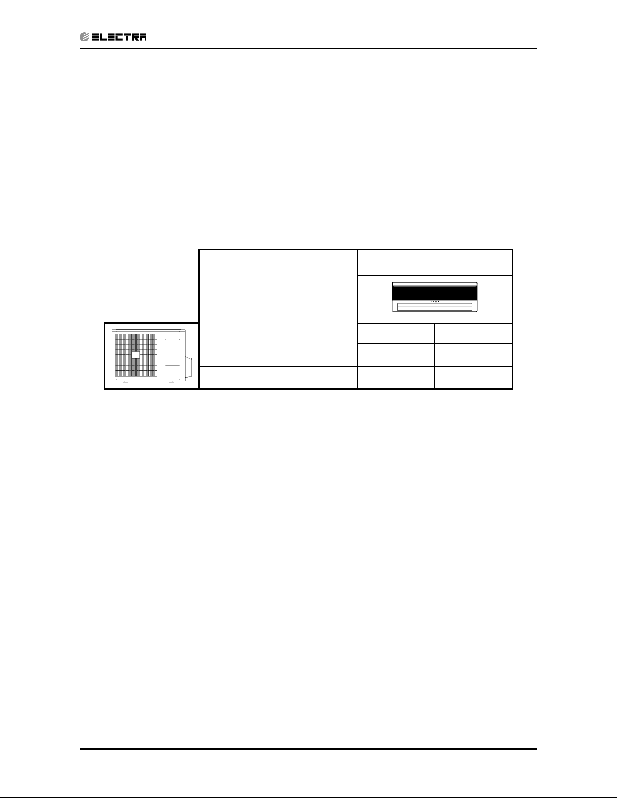
1.9 Matching Table
OUTDOOR UNITS
INDOOR UNITS
MODEL REFR” Delta 25 Delta 35
DCR 25 R410A √
DCR 35 R410A
√
Page 7
2-1
PRODUCT DATA SHEET
Revision Y05-01Service Manual - Delta DCI
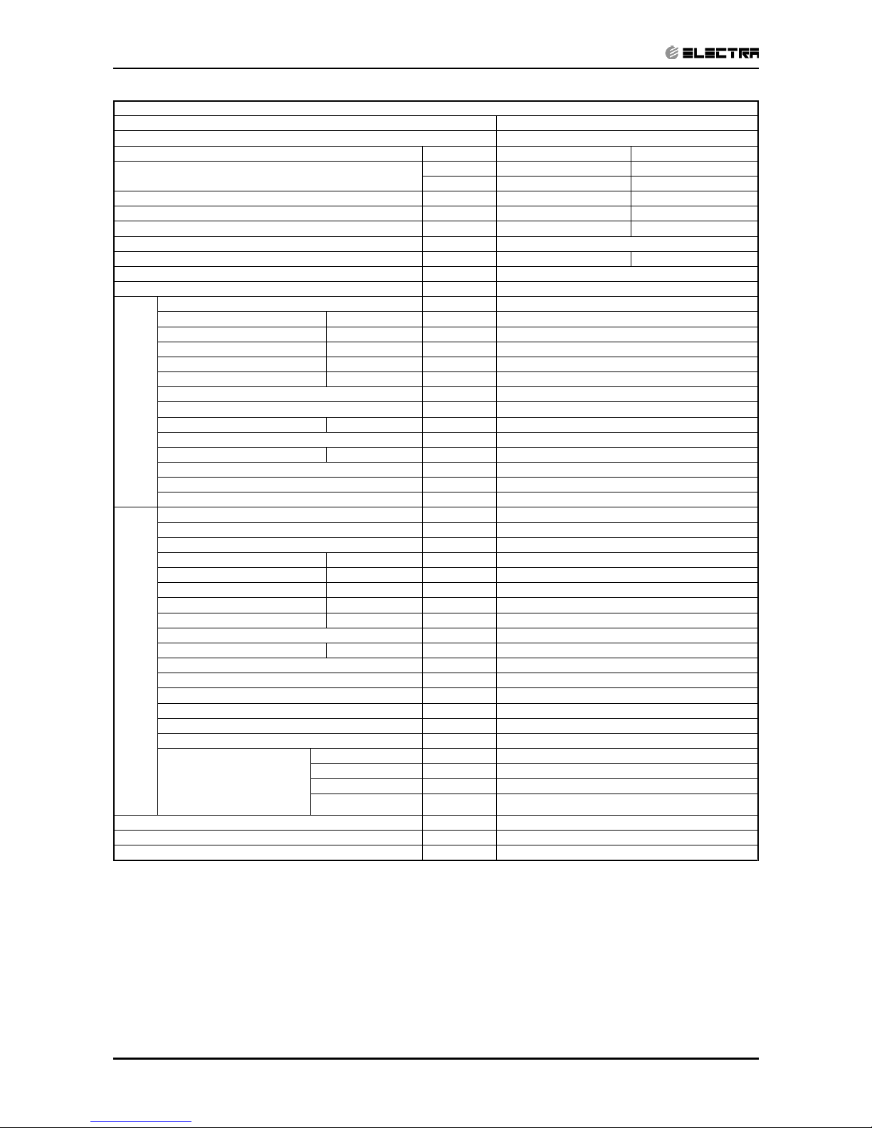
2. PRODUCT DATA SHEET
2.1 R410A
Model Indoor Unit DELTA 25
Model Outdoor Unit DCR 25
Installation Method of Pipe Flared
Characteristics Units Cooling Heating
Capacity
(1)
Btu/hr 8530(4440-10240) 9550(4774-11940)
kW 2.5(1.3-3.0) 2.8(1.4-3.5)
Power input
(1)
kW 0.75 0.82
EER (Cooling) or COP(Heating)
(1)
W/W 3.38 3.41
Energy efficiency class A B
Power supply V/Ph/Hz 220-240V/Single/50Hz
Rated current A 3.2 3.6
Starting current A 10
Circuit breaker rating A 12
INDOOR
Fan type & quantity Crossflow x 1
Fan speeds H/M/L RPM 1200/1050/850
Air flow
(2)
H/M/L m3/hr 420/350/270
External static pressure Min-Max Pa 0
Sound power level
(3)
H/M/L dB(A) 52/48/45
Sound pressure level
(4)
H/M/L dB(A) 39/35/32
Moisture removal l/hr 1
Condensate drain tube I.D mm 16
Dimensions WxHxD mm 680x200x250
Weight kg 7
Package dimensions WxHxD mm 740x265x320
Packaged weight kg 10
Units per pallet units 36 units per pallet
Stacking height units 9 levels
OUTDOOR
Refrigerant control EEV
Compressor type, model Rotary, Panasonic 5RS092XDJ01
Fan type & quantity Propeller(direct) x 1
Fan speeds H/L RPM 760
Air flow H/L m3/hr 1390
Sound power level H/L dB(A) 64
Sound pressure level
(4)
H/L dB(A) 54
Dimensions WxHxD mm 760x245x545
Weight kg 36
Package dimensions WxHxD mm 880x310x610
Packaged weight kg 39
Units per pallet Units 12 units per pallet
Stacking height units 3 levels
Refrigerant type R410A
Refrigerant chargless distance kg/m 0.85kg/7.5m
Additional charge per 1 meter g/m No need
Connections between
units
Liquid line In.(mm) 1/4”(6.35)
Suction line In.(mm) 3/8”(9.53)
Max.tubing length m. Max.15
Max.height
difference
m. Max. 10
Operation control type Remote control
Heating elements kW
Others
(1) Rating conditions in accordance with ISO 5151 and ISO 13253 (for ducted units) and EN 14511.
(2) Airflow in ducted units; at nominal external static pressure.
(3) Sound power in ducted units is measured at air discharge.
(4) Sound pressure level measured at 1 meter distance from unit.
Page 8
2-2
PRODUCT DATA SHEET
Revision Y05-01 Service Manual - Delta DCI
Model Indoor Unit DE LTA 35
Model Outdoor Unit DCR 35
Installation Method of Pipe Flared
Characteristics Units Cooling Heating
Capacity
(1)
Btu/hr 11940(4440-13990) 12280(5115-13990)
kW 3.5(1.3-4.1) 3.6(1.65-4.1)
Power input
(1)
kW 1.03 1.05
EER (Cooling) or COP(Heating)
(1)
W/W 3.39 3.43
Energy efficiency class A B
Power supply V/Ph/Hz 220-240V/Single/50Hz
Rated current A 4.9 4.8
Starting current A 10.5
Circuit breaker rating A 15
INDOOR
Fan type & quantity Crossflow x 1
Fan speeds H/M/L RPM 1200/1000/850
Air flow
(2)
H/M/L m3/hr 550/450/350
External static pressure Min-Max Pa 0
Sound power level
(3)
H/M/L dB(A) 52/46/42
Sound pressure leve
l
(4)
H/M/L dB(A) 39/33/29
Moisture removal l/hr 1.5
Condensate drain tube I.D mm 16
Dimensions WxHxD mm 840x200x250
Weight kg 8
Package dimensions WxHxD mm 930x265x320
Packaged weight kg 11
Units per pallet units 36 units per pallet
Stacking height units 9 levels
OUTDOOR
Refrigerant control EEV
Compressor type, model Rotary, Panasonic 5RS102XAB
Fan type & quantity Propeller(direct) x 1
Fan speeds H/L RPM 760
Air flow H/L m3/hr 1390
Sound power level H/L dB(A) 65
Sound pressure level
(4)
H/L dB(A) 55
Dimensions WxHxD mm 760x245x545
Weight kg 37
Package dimensions WxHxD mm 880x310x610
Packaged weight kg 40
Units per pallet Units 12 units per pallet
Stacking height units 3 levels
Refrigerant type R410A
Refrigerant chargless distance kg/m 1.0kg/7.5m
Additional charge per 1 meter g/m No need
Connections between units
Liquid line In.(mm) 1/4”(6.35)
Suction line In.(mm) 3/8”(9.53)
Max.tubing length m. Max.15
Max.height
difference
m. Max. 10
Operation control type Remote control
Heating elements kW No
Others
(1) Rating conditions in accordance with ISO 5151 and ISO 13253 (for ducted units) and EN 14511.
(2) Airflow in ducted units; at nominal external static pressure.
(3) Sound power in ducted units is measured at air discharge.
(4) Sound pressure level measured at 1 meter distance from unit.
Page 9
3-1
RATING CONDITIONS
Revision Y05-01Service Manual - Delta DCI
3. RATING CONDITIONS
Rating conditions in accordance with ISO 5151 and ISO 13253 (for ducted units).
Cooling:
Indoor: 27
o
C DB 19oC WB
Outdoor: 35
o
C DB
Heating:
Indoor: 20
o
C DB
Outdoor: 7
o
C DB 6oC WB
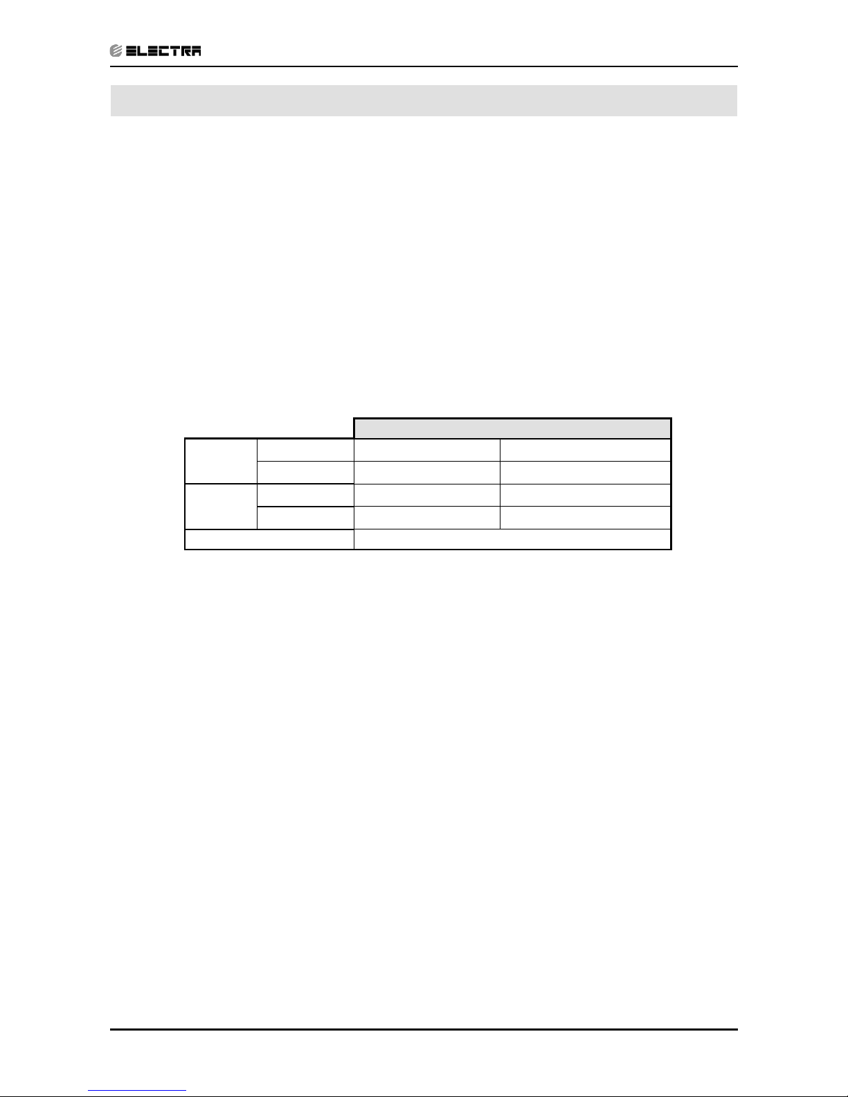
3.1 Operating Limits
3.1.1 R410A
Indoor Outdoor
Cooling
Upper limit
32oC DB 23oC WB 46oC DB
Lower limit
21oC DB 15oC WB 10oC DB
Heating
Upper limit
27oC DB 24oC DB 18oC WB
Lower limit
10oC DB -15oC DB -16oC WB
Voltag e
198 – 264 V
Page 10
4-1
OUTLINE DIMENSIONS
Revision Y05-01Service Manual - Delta DCI
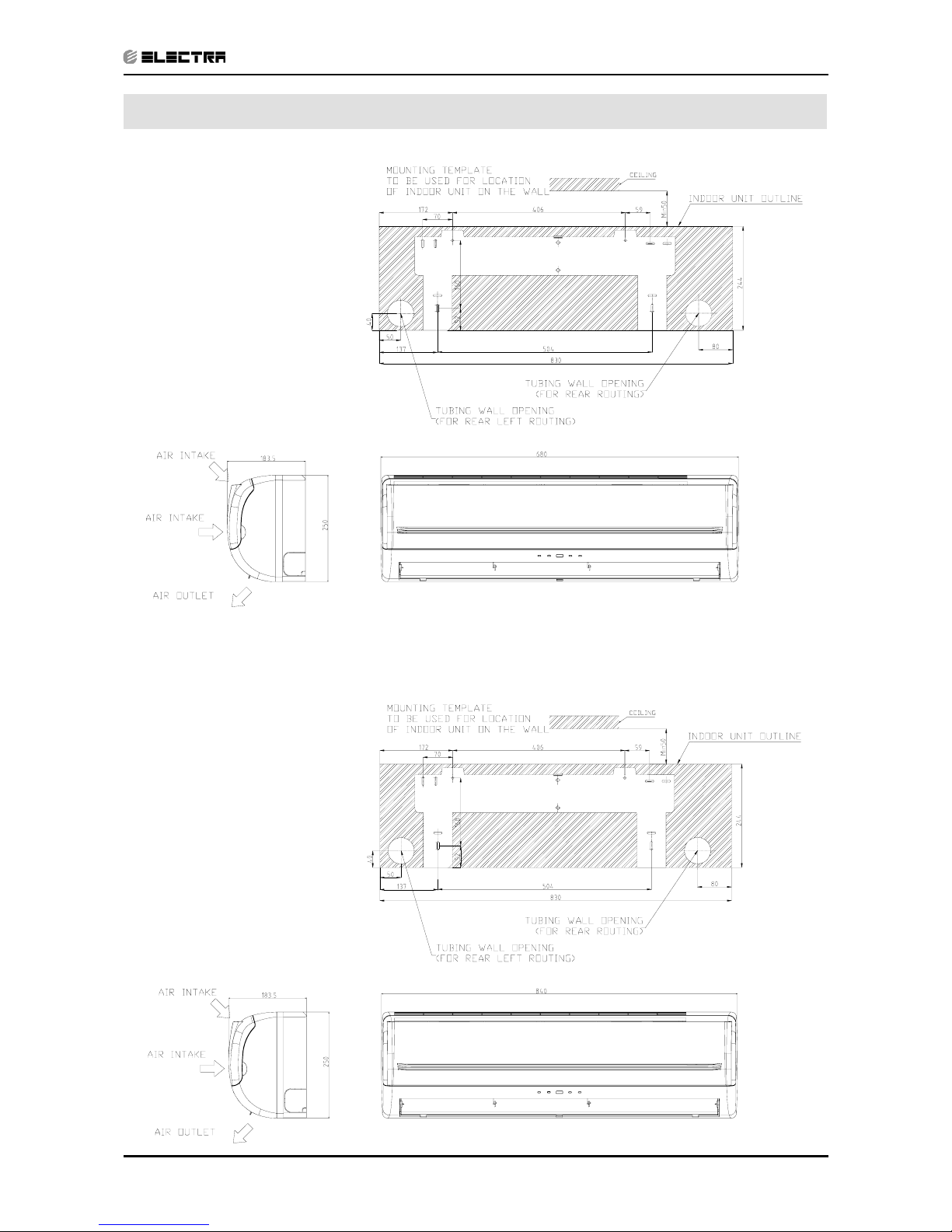
4. OUTLINE DIMENSIONS
4.1 Indoor Unit: Delta 25 DCI
4.2
Indoor Unit: Delta 35 DCI
Page 11
4-2
OUTLINE DIMENSIONS
Revision Y05-01 Service Manual - Delta DCI
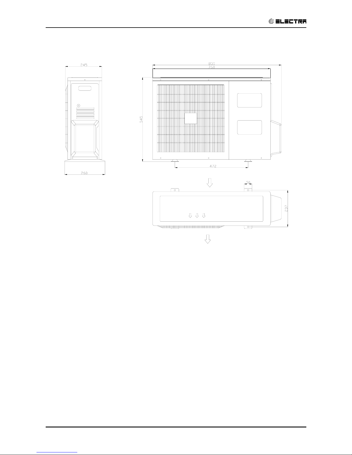
4.3 Outdoor Unit: DCR 25/35 DCI
AI R OUTL E T
AI R I NTAKE
Page 12
5-1
PERFORMANCE DATA & PRESSURE CURVES
Revision Y05-01Service Manual - Delta DCI
5. PERFORMANCE DATA
5.1 Delta 25 DCI
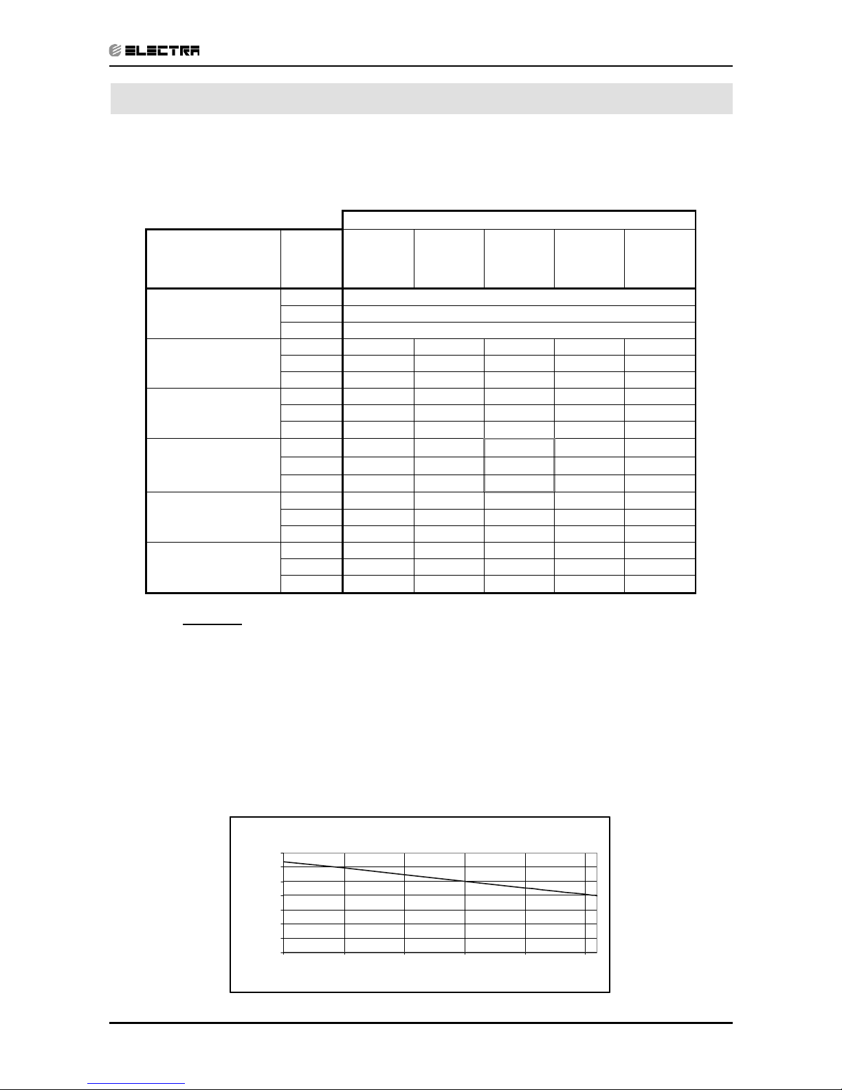
5.1.1 Cooling Capacity (kW) - Run Mode (Unit A or B)
230[V] : Indoor Fan at High Speed.
ID COIL ENTERING AIR DB/WB TEMPERATURE [
0
C]
OD COIL
ENTERING AIR DB
TEMPERATURE
[0C]
DATA
22/15 24/17 27/19 29/21 32/23
-10 - 20
(protection range)
TC 80 - 110 % of nominal
SC 80 - 105 % of nominal
PI 25 - 50 % of nominal
25
TC 2.41 2.57 2.73 2.89 3.05
SC 1.67 1.71 1.74 1.77 1.81
PI 0.57 0.58 0.60 0.61 0.62
30
TC 2.30 2.46 2.62 2.77 2.93
SC 1.63 1.67 1.70 1.76 1.77
PI 0.64 0.65
0.66
0.67 0.68
35
TC 2.18 2.34
2.50
2.66 2.82
SC 1.59 1.63 1.66 1.69 1.73
PI 0.71 0.72
0.73
0.74 0.75
40
TC 2.07 2.23
2.39
2.54 2.70
SC 1.55 1.59 1.62 1.65 1.69
PI 0.78 0.79 0.80 0.81 0.82
46
TC 1.93 2.09 2.25 2.41 2.56
SC 1.50 1.54 1.57 1.61 1.64
PI 0.86 0.87 0.88 0.89 0.90
LEGEND
TC – Total Cooling Capacity, kW
SC – Sensible Capacity, kW
PI – Power Input, kW
WB – Wet Bulb Temp., (
o
C)
DB – Dry Bulb Temp., (
o
C)
ID – Indoor
OD – Outdoor
5.1.2 Capacity Correction Factors
Cooling Capacity Ratio Vs. Outdoor Temperature
0.50
0.60
0.70
0.80
0.90
1.00
1.10
1.20
20 25 30 35 40 45
Outdoor Temperature [deg C]
Capacity Ratio
Page 13
5-2
PERFORMANCE DATA & PRESSURE CURVES
Revision Y05-01 Service Manual - Delta DCI
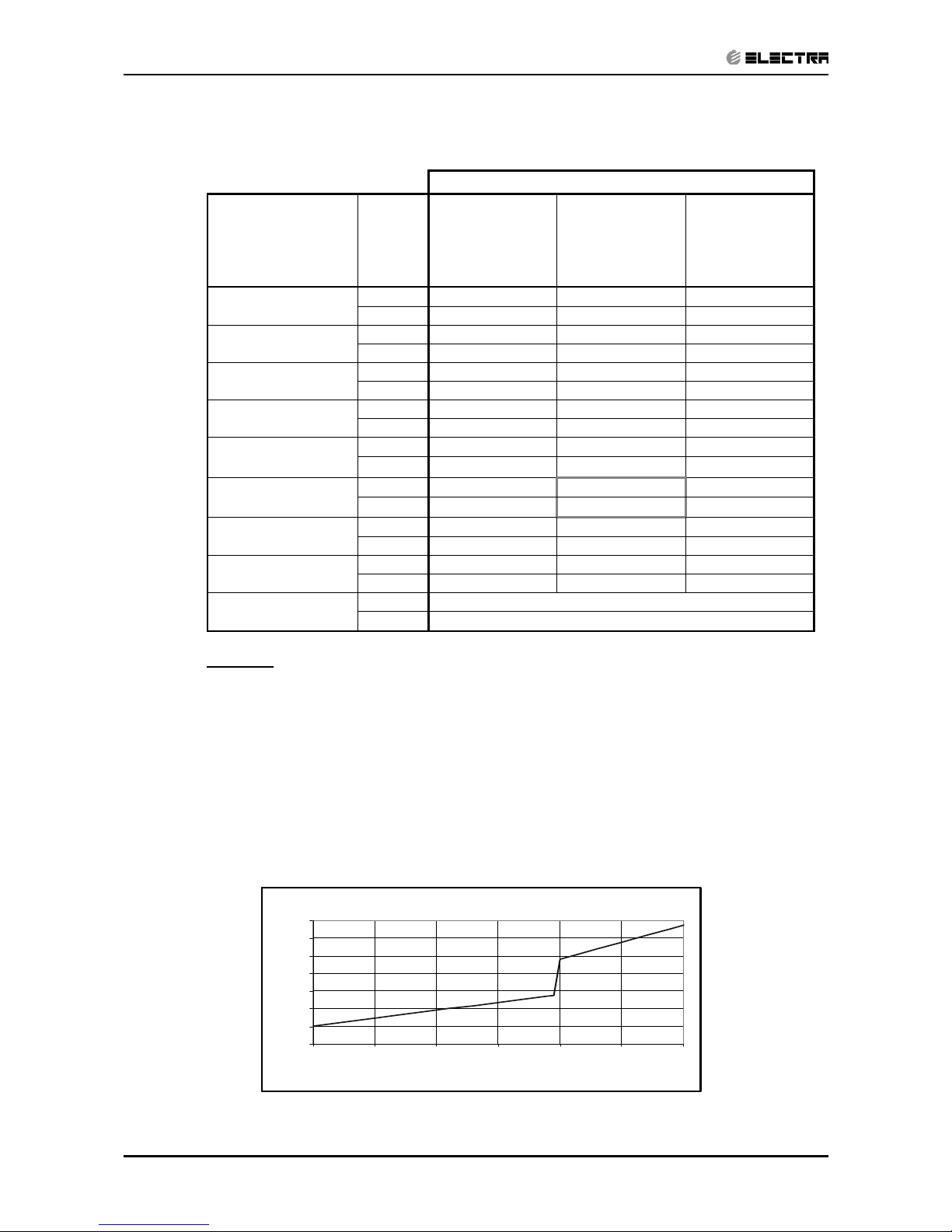
5.1.3 Heating Capacity (kW) - Run Mode(Unit A or B)
230[V] : Indoor Fan at High Speed.
ID COIL ENTERING AIR DB TEMPERATURE [0C]
OD COIL
ENTERING
AIR DB/WB
TEMPERATURE
[
0
C]
DATA 15 20 25
-15/-16
TC 1.78 1.66 1.53
PI 0.49 0.54 0.59
-10/-12
TC 1.98 1.86 1.73
PI 0.59 0.64 0.69
-7/-8
TC 2.14 2.01 1.89
PI 0.67 0.72 0.77
-1/-2
TC 2.21 2.09 1.96
PI 0.71 0.76 0.81
2/1
TC 2.26 2.14 2.01
PI 0.73
0.78
0.83
7/6
TC 32.92
2.80
2.68
PI 0.77
0.82
0.87
10/9
TC 3.09
2.96
2.84
PI 0.82 0.87 0.92
15/12
TC 3.25 3.12 3.00
PI 0.86 0.91 0.96
15-24
TC 85 - 105 % of nominal
(Protection Range)
PI 80 - 120 % of nominal
LEGEND
TC – Total Cooling Capacity, kW
PI – Power Input, kW
WB – Wet Bulb Temp., (
o
C)
DB – Dry Bulb Temp., (
o
C)
ID – Indoor
OD – Outdoor
5.1.4 Capacity Correction Factors
Hea ting Cap acity Ra tio V s. Outdoo r Te mperature
0.50
0.60
0.70
0.80
0.90
1.00
1.10
1.20
-15 -10 -5 0 5 10 15
Outdoor WB Temperature [deg C]
Capacit y Ration
Page 14
5-3
PERFORMANCE DATA & PRESSURE CURVES
Revision Y05-01Service Manual - Delta DCI
5.2 Delta 35 DCI
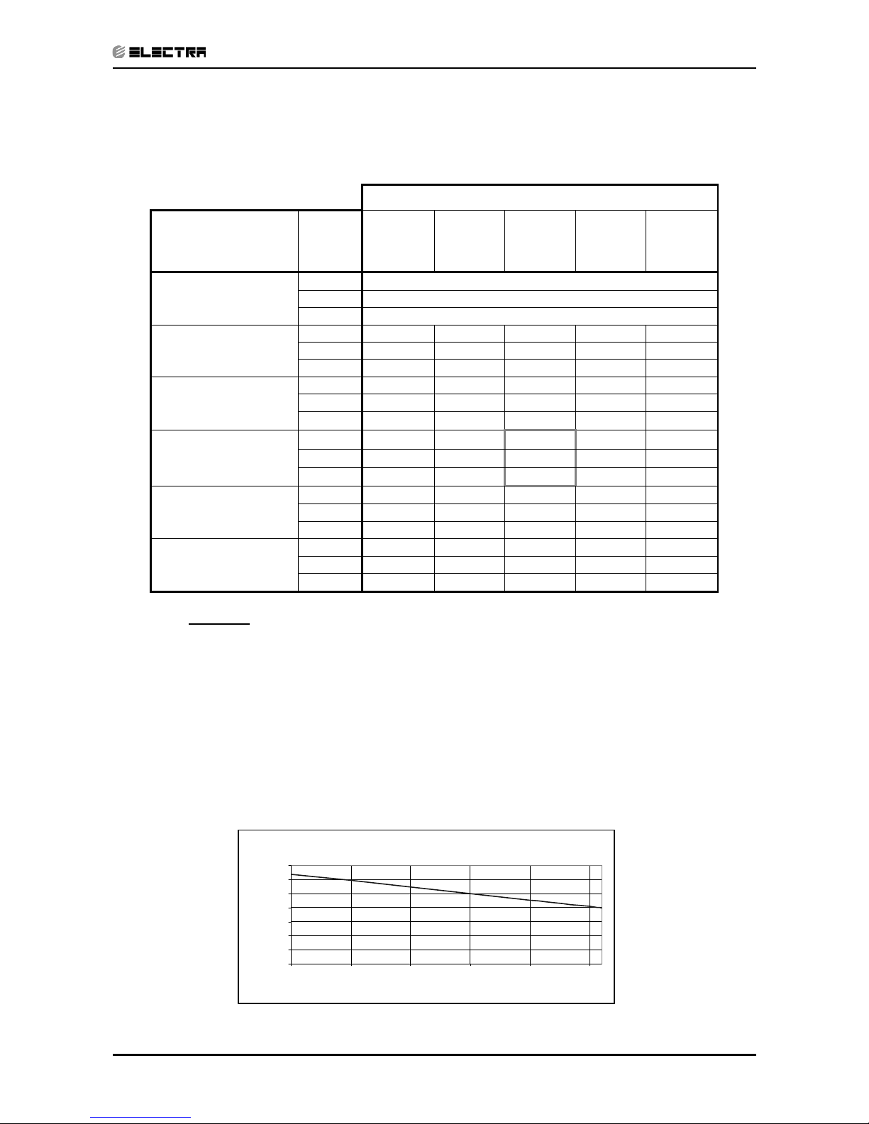
5.2.1 Cooling Capacity (kW) - Run Mode (Unit A or B)
230[V] : Indoor Fan at High Speed.
ID COIL ENTERING AIR DB/WB TEMPERATURE [0C]
OD COIL
ENTERING AIR DB
TEMPERATURE [
0
C]
DATA
22/15 24/17 27/19 29/21 32/23
-10 - 20
(protection range)
TC 80 - 110 % of nominal
SC 80 - 105 % of nominal
PI 25 - 50 % of nominal
25
TC 3.38 3.60 3.82 4.04 4.26
SC 2.54 2.59 2.64 2.69 2.74
PI 0.79 0.81 0.82 0.84 0.85
30
TC 3.22 3.44 3.66 3.88 4.10
SC 2.48 2.53 2.58 2.63 2.68
PI 0.89 0.90
0.92
0.93 0.95
35
TC 3.06 3.28
3.50
3.72 3.94
SC 2.42 2.47 2.52 2.57 2.62
PI 0.98 0.99
1.01
1.03 1.04
40
(Protection Range)
TC 2.90 3.12
3.34
3.56 3.78
SC 2.36 2.41 2.46 2.51 2.56
PI 1.07 1.09 1.10 1.12 1.13
46
(Protection Range)
TC 2.70 2.92 3.15 3.37 3.59
SC 2.28 2.34 2.39 2.44 2.49
PI 1.18 1.20 1.21 1.23 1.24
LEGEND
TC – Total Cooling Capacity, kW
SC – Sensible Capacity, kW
PI – Power Input, kW
WB – Wet Bulb Temp., (
o
C)
DB – Dry Bulb Temp., (
o
C)
ID – Indoor
OD – Outdoor
5.2.2 Capacity Correction Factors
Cooling Capacity Ratio Vs. Outdoor Temperature
0.50
0.60
0.70
0.80
0.90
1.00
1.10
1.20
20 25 30 35 40 45
Outdoor Temperature [deg C]
Capacity Ratio
Page 15
5-4
PERFORMANCE DATA & PRESSURE CURVES
Revision Y05-01 Service Manual - Delta DCI
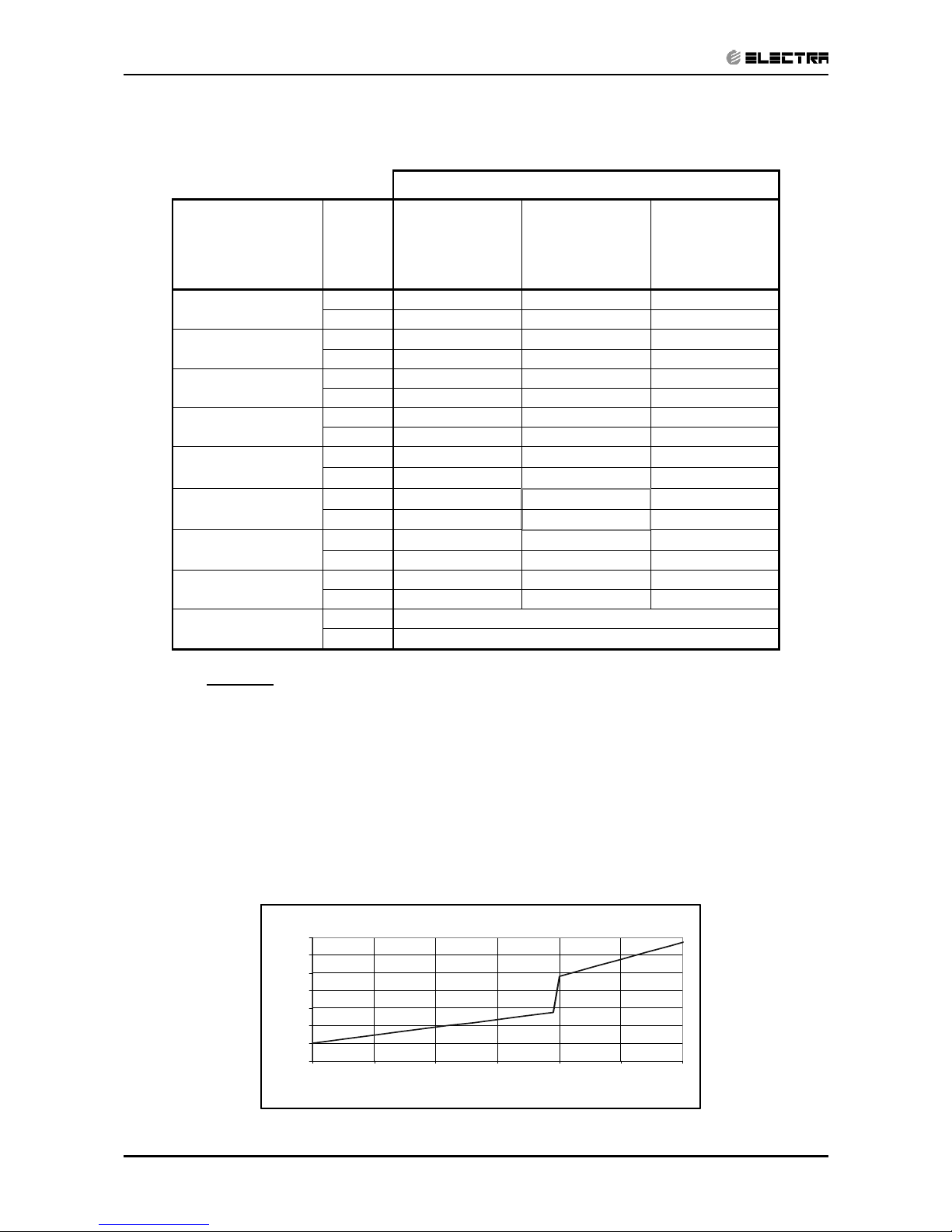
5.2.3 Heating Capacity (kW) - Run Mode(Unit A or B)
230[V] : Indoor Fan at High Speed.
ID COIL ENTERING AIR DB TEMPERATURE [0C]
OD COIL
ENTERING
AIR DB/WB
TEMPERATURE
[
0
C]
DATA 15 20 25
-15/-16
TC 2.29 2.13 1.97
PI 0.61 0.67 0.73
-10/-12
TC 2.55 2.39 2.23
PI 0.73 0.79 0.85
-7/-8
TC 2.75 2.58 2.42
PI 0.82 0.89 0.95
-1/-2
TC 2.84 2.68 2.52
PI 0.87 0.93 0.99
2/1
TC 2.91 2.75 2.59
PI 0.90
0.96
1.02
7/6
TC 3.76
3.60
3.44
PI 0.95
1.01
1.07
10/9
TC 3.97
3.81
3.65
PI 1.01 1.07 1.13
15/12
TC 4.17 4.01 3.85
PI 1.06 1.12 1.18
15-24
TC 85 - 105 % of nominal
(Protection Range)
PI 80 - 120 % of nominal
LEGEND
TC – Total Cooling Capacity, kW
PI – Power Input, kW
WB – Wet Bulb Temp., (
o
C)
DB – Dry Bulb Temp., (
o
C)
ID – Indoor
OD – Outdoor
5.2.4 Capacity Correction Factors
Hea ting Cap acity Ra tio V s. Outdoo r Te mperature
0.50
0.60
0.70
0.80
0.90
1.00
1.10
1.20
-15 -10 -5 0 5 10 15
Outdoor WB Temperature [deg C]
Capacit y Ration
Page 16
5-5
PERFORMANCE DATA & PRESSURE CURVES
Revision Y05-01Service Manual - Delta DCI
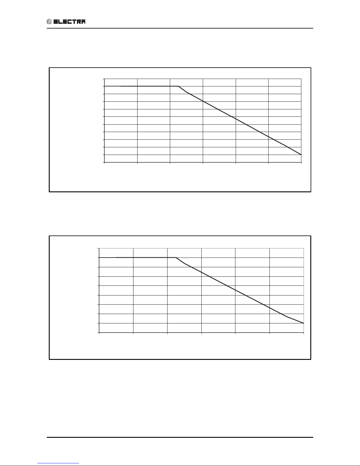
5.3 Capacity Correction Factor Due to Tnbing Length
5.3.1 Delta 25 DCI: Cooling
5.3.2 Heating
0.90
0.91
0.92
0.93
0.94
0.95
0.96
0.97
0.98
0.99
1.00
1.01
3579111315
Tubing Length [m]
Capacity Ratio
0.84
0.86
0.88
0.90
0.92
0.94
0.96
0.98
1.00
1.02
3579111315
Tubing Length [m]
Capacity Ratio
Page 17
5-6
PERFORMANCE DATA & PRESSURE CURVES
Revision Y05-01 Service Manual - Delta DCI
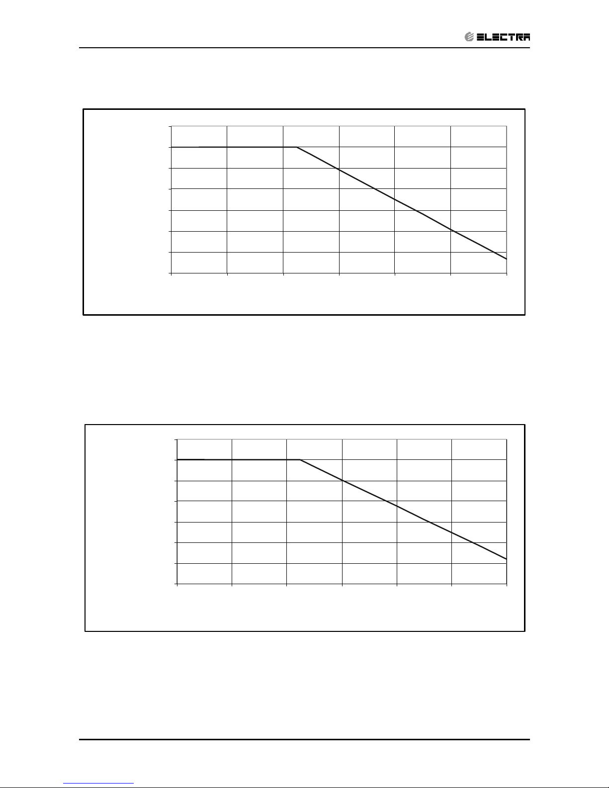
5.3.3 Delta 35 DCI: Cooling
5.3.4 Heating
0.94
0.95
0.96
0.97
0.98
0.99
1.00
1.01
3 5 7 9 11 13 15
Tubing Length [m]
Capacity Ratio
0.97
0.98
0.98
0.99
0.99
1.00
1.00
1.01
3 5 7 9 11 13 15
Tubing Length [m]
Capacity Ratio
Page 18
5-7
PERFORMANCE DATA & PRESSURE CURVES
Revision Y05-01Service Manual - Delta DCI
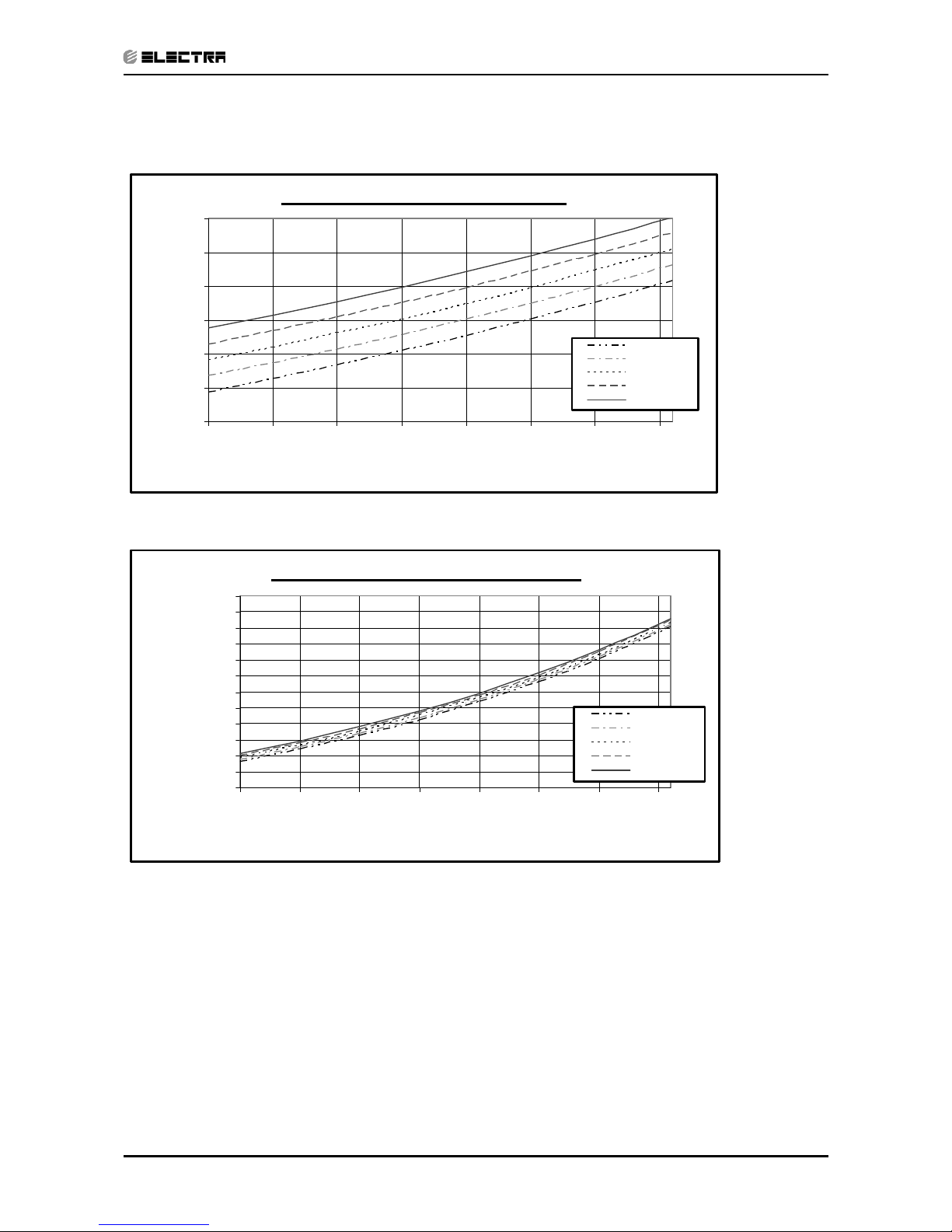
5.4 Pressure Curves
5.4.1. Model: Delta 25 DCI Cooling — Test Mode
Suction Pressure VS.Outdoor Temp.
500
600
700
800
900
1000
1100
10 15 20 25 30 35 40 45
Outdoor DB Temperature [ºC]
Suction Pressure [kPa]
22/15 D B/WB
24/17 D B/WB
27/19 D B/WB
29/21 D B/WB
32/23 D B/WB
Discharge Pressure VS. Outdoor Temp.
1000
1250
1500
1750
2000
2250
2500
2750
3000
3250
3500
3750
4000
10 15 20 25 30 35 40 45
Outdoor DB Temperature [ºC]
Discharge Pressure [kPa]
22/15 D B/WB
24/17 D B/WB
27/19 D B/WB
29/21 D B/WB
32/23 D B/WB
Page 19
5-8
PERFORMANCE DATA & PRESSURE CURVES
Revision Y05-01 Service Manual - Delta DCI
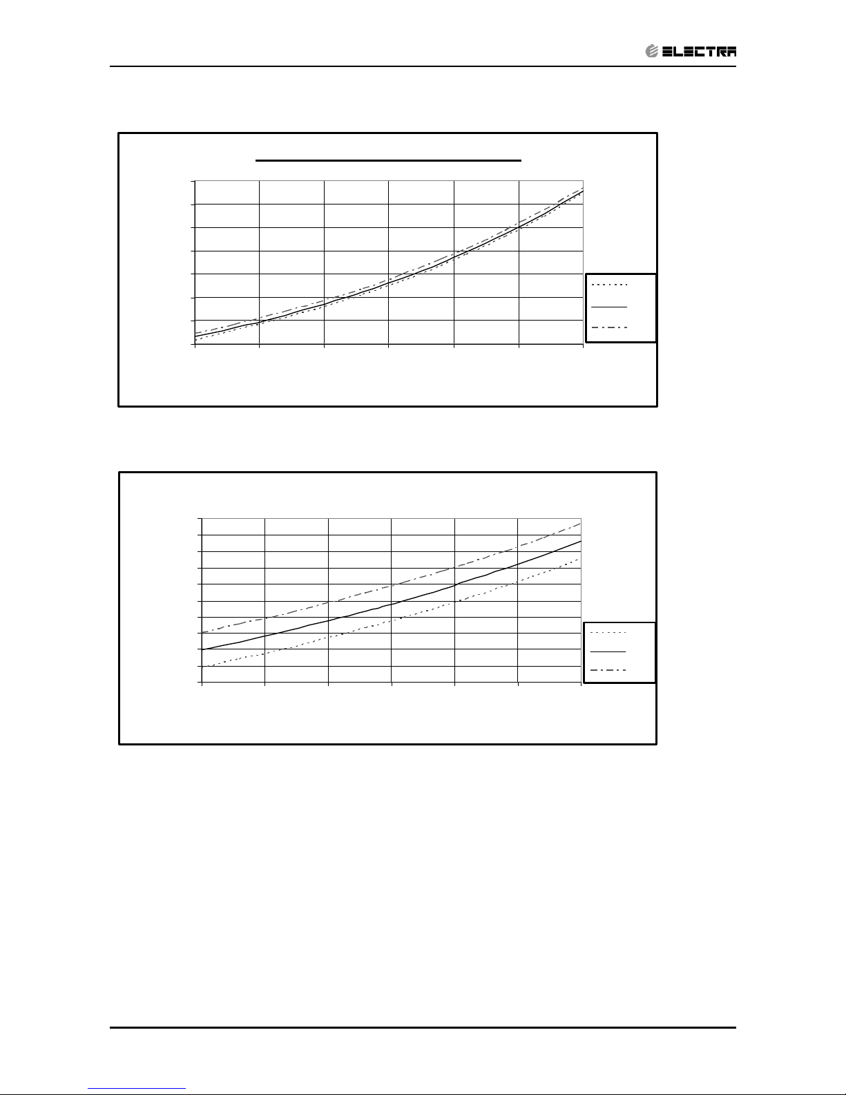
5.4.2 Heating — Test Mode.
Suction Pressure VS. Outdoor Temp.
300
400
500
600
700
800
900
1000
-15 -10 -5 0 5 10 15
Outdoor WB Temperature [ºC]
Suction Pressure [kPa]
15 DB
20 DB
25 DB
Discharge Pressure VS. Outdoor Temp.
1500
1750
2000
2250
2500
2750
3000
3250
3500
3750
4000
-15 -10 -5 0 5 10 15
Outdoor WB Temperature [ºC]
Discharge Pressure [kPa]
15 DB
20 DB
25 DB
Page 20
5-9
PERFORMANCE DATA & PRESSURE CURVES
Revision Y05-01Service Manual - Delta DCI
5.5 Model: Delta 35 DCI Cooling — Test Mode
Suction Pressure VS. Outdoor Temp.
400
500
600
700
800
900
1000
1100
1200
10 15 20 25 30 35 40 45
Outdoor DB Temperature [ºC]
Suction Pressure [kPa]
22/15 D B/WB
24/17 D B/WB
27/19 D B/WB
29/21 D B/WB
32/23 D B/WB
Discharge Pressure VS. Outdoor Temp.
1000
1250
1500
1750
2000
2250
2500
2750
3000
3250
3500
3750
4000
10 15 20 25 30 35 40 45
Outdoor DB Temperature [ºC]
Discharge Pressure [kPa]
22/15 DB /WB
24/17 DB /WB
27/19 DB /WB
29/21 DB /WB
32/23 DB /WB
Page 21
5-10
PERFORMANCE DATA & PRESSURE CURVES
Revision Y05-01 Service Manual - Delta DCI
5.6 Heating — Test Mode
Suction Pressure VS. Outdoor Temp.
300
400
500
600
700
800
900
1000
-15 -10 -5 0 5 10 15
Outdoor WB Tempera ture [ºC]
Suction Pressure [kPa]
15 DB
20 DB
25 DB
Discharge Pressure VS. Outdoor Temp.
1500
1750
2000
2250
2500
2750
3000
3250
3500
3750
4000
-15 -10 -5 0 5 10 15
Outdoor WB Temperature[ºC]
Discharge Pressure [kPa]
15 DB
20 DB
25 DB
Page 22

6-1
SOUND LEVEL CHARACTERISTICS
Revision Y05-01Service Manual - Delta DCI
6. SOUND LEVEL CHARACTERISTICS
6.1 Sound Pressure Level
Figure 1. Wall Mounted Figure 2. Floor Mounted
Figure 3. Ducted Figure 4. Cassette
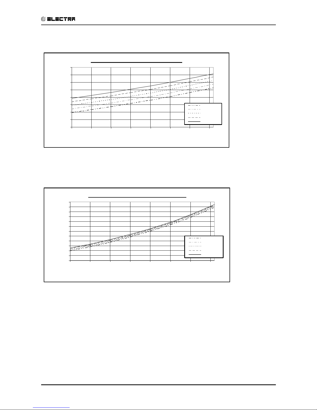
6.2 Soud Pressure Level Spectrum (Measured as Figure 1)
Delta 25 Delta 35
BAND CENTER FREQUENCIES, Hz
APPROXIMATE
THRESHOLD OF
HEARING FOR
CONTINUOUS
NOISE
NC-70
NC-60
NC-50
NC-40
NC-30
NC-20
OCTAVE BAND SOUND PRESSURE LEVEL, dB re 0.002 MICRO BAR
BAND CENTER FREQUENCIES, Hz
APPROXIMATE
THRESHOLD OF
HEARING FOR
CONTINUOUS
NOISE
NC-70
NC-60
NC-50
NC-40
NC-30
NC-20
OCTAVE BAND SOUND PRESSURE LEVEL, dB re 0.002 MICRO BAR
FAN SPEED LINE
HI
ME
LO
Page 23
6-2
SOUND LEVEL CHARACTERISTICS
Revision Y05-01 Service Manual - Delta DCI
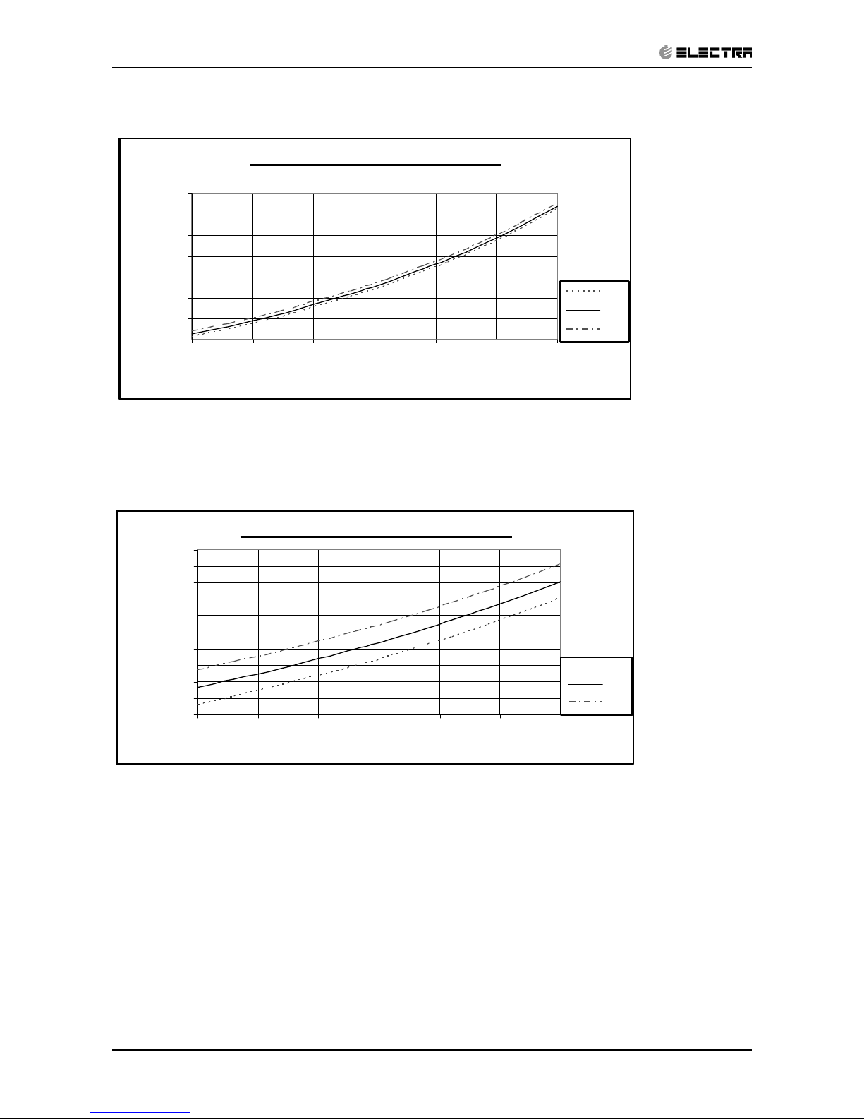
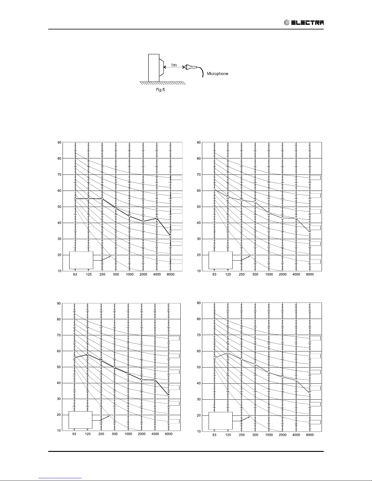
6.3 Outdoor units
6.4 Sound Pressure Level Spectrum (Measured as Figure 5)
DCR 25 Cooling DCR 25 Heating
DCR 35 Cooling DCR 35 Heating
Microphone Distance from Unit
BAND CENTER FREQUENCIES, Hz
APPROXIMATE
THRESHOLD OF
HEARING FOR
CONTINUOUS
NOISE
NC-70
NC-60
NC-50
NC-40
NC-30
NC-20
OCTAVE BAND SOUND PRESSURE LEVEL, dB re 0.002 MICRO BAR
BAND CENTER FREQUENCIES, Hz
APPROXIMATE
THRESHOLD OF
HEARING FOR
CONTINUOUS
NOISE
NC-70
NC-60
NC-50
NC-40
NC-30
NC-20
OCTAVE BAND SOUND PRESSURE LEVEL, dB re 0.002 MICRO BAR
BAND CENTER FREQUENCIES, Hz
APPROXIMATE
THRESHOLD OF
HEARING FOR
CONTINUOUS
NOISE
NC-70
NC-60
NC-50
NC-40
NC-30
NC-20
OCTAVE BAND SOUND PRESSURE LEVEL, dB re 0.002 MICRO BAR
BAND CENTER FREQUENCIES, Hz
APPROXIMATE
THRESHOLD OF
HEARING FOR
CONTINUOUS
NOISE
NC-70
NC-60
NC-50
NC-40
NC-30
NC-20
OCTAVE BAND SOUND PRESSURE LEVEL, dB re 0.002 MICRO BAR
Page 24

7-1
ELECTRICAL DATA
Revision Y05-01Service Manual - Delta DCI
7. ELECTRICAL DATA
7.1 Single Phase Units
MODEL Delta 25 Delta 35
Power Supply
To indoor To indoor
1PH,220-240V,50Hz 1PH,220-240V,50Hz
Max Current, A 6.3 7.5
Circuit Breaker,A 12 15
Power Supply Wiring No. X
Cross Section mm
2
3x1.0 mm
2
3x1.5 mm
2
Interconnecting Cable RC
Model No. X Cross Section mm
2
4x1.0 mm
2
5x1.5 mm
2
NOTE
Power wiring cord should comply with local lows and electrical
regulations requirements
Page 25

8-1
WIRING DIAGRAMS
Revision Y05-01Service Manual - Delta DCI
8. WIRING DIAGRAMS
8.1 Delta 25/35 DCR 25/35 DCI
Blue
Blue
Blue
Blue
N/3
Indoor unit controller PCB
Note: The dashed part is optional
Power supply
~230V 50Hz
J3
INDOOR UNIT CIRCUIT DIAGRAM
P20P19
P2
3 4
P1
1 2
P4
P3 P9 P11
Outdoor unit controller PCB
EEV
P7
N
COML
P10
4
5
6
23
1
Y/G
Y/G
C/5
Brown
L/4
Red
Brown
Red
Y/G
Brown
Red
C
N
L
Jumper
Flash
4
3
2
JP9
1
JP1
6
5
31
24
P10 P1
P8
P22
To metal sheet
1
2
JUMPER
J1
J2
L-OFAN
OFAN
1 2
Red
OUTDOOR UNIT CIRCUIT DIAGRAM
Reverse
COMP
Red
Black
Brown
W
V
U
1
2
Blue
H-OFAN
Yellow
capacitor
2uF 450V
valve
Green
3 4
Black
1
2
11
22
Sheet
Y/G
NEUTRAL
To Metal
red
blue
1uF 450V
gray
gray
black
white
P4
P15P16 P11 P3P14P19
2112
PH-12
P5(white)
( red)
P9
brown
capacitor
312
5
6
4
Display
OCT
OAT CTT
IFAN
ICT
RAT
Brown
Y/G
P2
P20
32
3
4
1
4
MEGATOOL
P7(White)
J4
P13
M1
FLASH
3
3
45
2
1
1
2
P6(White)
54
6
Step motor
magnetic ring
Page 26

9-1
REFRIGERATION DIAGRAMS
Revision Y05-01Service Manual - Delta DCI
9. REFRIGERATION DIAGRAMS
9.1 Heat Pump Models
9.1.1 Delta 25/35 DCR 25/35 DCI => Cooling Mode
EEV
EEV
Page 27

10-1
TUBING CONNECTIONS
Revision Y05-01Service Manual - Delta DCI
10. TUBING CONNECTIONS
TUBE (Inch)
TORQUE (Nm)
¼” ⅜” ½” ⅝” ¾”
Flare Nuts 11-13 40-45 60-65 70-75 80-85
Valve Cap 13-20 13-20 18-25 18-25 40-50
Service Port Cap 11-13 11-13 11-13 11-13 11-13
1. Valve Protection Cap-end
2. Refrigerant Valve Port (use Allen wrench to open/close)
3. Valve Protection Cap
4. Refrigerant Valve
5. Service Port Cap
6. Flare Nut
7. Unit Back Side
8. Copper Tube
When the outdoor unit is installed above the indoor unit an oil trap is required every 5m along the suction
line at the lowest point of the riser. Incase the indoor unit is installed above the outdoor, no trap is
required.
Page 28

11-1
CONTROL SYSTEM
Revision Y05-01Service Manual - Delta DCI
11. CONTROL SYSTEM
11.1 General Functions and Operating Rules
The DCI software is fully parametric.All the model dependent parameters are shown in Blue color
and with Italic style [parameter].
The parameters values are given in the last section of this control logic chapter of the service
manual.
11.1.1 System Operation Concept
The control function is divided between indoor and outdoor unit controllers. Indoor unit is the system
‘Master’, requesting the outdoor unit for cooling/heating capacity supply. The outdoor unit is the
system ‘Slave’ and it must supply the required capacity unless it enters into a protection mode
avoiding it from supplying the requested capacity.
The capacity request is transferred via indoor to outdoor communication, and is represented by a
parameter called ‘NLOAD’. NLOAD is an integer number with values between 0 and 127, and it
represents the heat or cool load felt by the indoor unit.
11.1.2 Compressor Frequency Control (NLOAD setting)
The NLOAD setting is done by the indoor unit controller, based on a PI control scheme.
The actual NLOAD to be sent to the outdoor unit controller, is based on the preliminary LOAD
calculation, the indoor fan speed, and the power shedding function.
NLOAD limits as a function of indoor fan speed:
Indoor Fan Speed Maximum NLOAD Cooling Maximum NLOAD Heating
Low Max NLOADIF1C 127
Medium Max NLOADIF2C 127
High Max NLOADIF3C 127
Turbo Max NLOADIF4C 127
Auto Max NLOADIF5C 127
11.1.3 Target Frequency Setting
The compressor target frequency is a function of the NLOAD number sent from the indoor
controller and the outdoor air temperature.
Basic Target Frequency Setting:
NLOAD Target Frequency
127 Maximum frequency
10 < NLOAD < 127 Interpolated value between minimum and maximum frequency
10 Minimum frequency
0 Compressor is stopped
Page 29

11-2
CONTROL SYSTEM
Revision Y05-01 Service Manual - Delta DCI
Target frequency limits as a function of outdoor air temperature (OAT):
OAT Range Cool mode limits Heat mode limits
OAT < 6
MaxFreqAsOATC
No limit
6 ≤ OAT < 15 MaxFreqAsOAT1H
15 ≤ OAT < 28
MaxFreqAsOAT2H
28 ≤ OAT No limit
11.1.4 Frequency Changes Control
Frequency change rate is 1 Hz/sec.
11.1.5 Compressor Starting Control
11.1.6 Minimum On and Off Time
3 minutes.
11.1.7 Indoor Fan Control
10 Indoor fan speeds are determined for each model. 5 speeds for cool/dry/fan modes and 5
speeds for heat mode.
When user sets the indoor fan speed to a fixed speed (Low/ Medium/ High), unit will operate
constantly at set speed.
When Auto Fan is selected, indoor unit controller can operate in all speeds. The actual speed is set
according to the cool/heat load.
11.1.8 Turbo Speed
The Turbo speed is activated during the first 30 minutes of unit operation when auto fan speed is
selected and under the following conditions:
• Difference between set point and actual room temperature is bigger then 3 degrees.
• Room temperature > 22 for cooling, or < 25 for heating.
Frequency
Time
Min 10 Minutes
1
Minute
Step 1
Step 3
1
Minute
Step 2
Page 30

11-3
CONTROL SYSTEM
Revision Y05-01Service Manual - Delta DCI
11.1.9 Heating Element Control
Heating element can be started if LOAD > 0.8 * MaximumNLOAD AND Indoor Coil
temperature < 45.
The heating element will be stopped when LOAD < 0.5 * MaximumNLOAD OR if Indoor Coil
temperature > 50.
11.1.10 Outdoor Fan Control
• The OFAN motor is an AC type that operates with 2 speeds (Low/High),
controlled by Relays.
• OFAN speed depends on the compressor Target Frequency, and it’s set according to the
following table and graphs.
• OFAN can change its Speed only if it has been working in the current
speed for
at least 35 seconds:
Compressor
Target Frequency
OFAN Speed
Normal cases
State A at cool / Heat
State B
at cool
State C
at cool
OAT>15
o
C
at heat
Freq=0 OFF OFF OFF OFF
10 ≤ Freq < OFLowFreq Low Low Low Low
OFLowFreq ≤ Freq< OFMedFreq High Low Low Low
OFMedFreq≤ Freq High Low Low High
Notes:
When OAT is faulty or disabled OFAN will follow ‘Normal cases’ rules (left column).
1. OFLowFreq =
OFLowFreqC in cool mode, and OFLowFreqH in heat mode.
2. OFMedFreq =
OFMedFreqC in cool mode, and OFMedFreqH in heat mode.
The OFAN will be off when the compressor is off.
• An exception for the following rule is when compressor was operating in cool
mode before stopped. In this case OFAN will remain on in low speed for 1
minute.
• Whenever the indoor unit is under indoor coil overheating protection, as long as the
protection status is HzD2, the outdoor fan will change to off. It will be enabled to be back on
when the status of this protection becomes normal.
• Upon receiving night mode signal (ON), through communication, the OFAN will be
operating in LOW speed only in Cool. It will be back to its normal operation when receiving
OFF signal.
OAT
OFAN Stat
e
at Cool Mode
20
A
B
C
3 Degrees
3 Degrees
7
Not e: Pe r i or i t i es A>B>C
Page 31

11-4
CONTROL SYSTEM
Revision Y05-01 Service Manual - Delta DCI
11.1.1 EEV (electronic Expansion valve) Control
EEV opening is defined as EEV = EEVOL + EEV
CV
EEVOL is the initial EEV opening as a function of the compressor frequency, operation mode, unit
model and capacity.
EEV
CV
is a correction value for the EEV opening that is based on the compressor temperature.
During the first 5 minutes of compressor operation EEV
CV
= 0.
Once the first 5 minutes are over, the correction value is calculated as follow: EEV
CV
(n) = EEVCV(n-
1) + EEV
CTT
EEV
CTT
is the correction based on the compressor temperature. A target compressor temperature is
set depending on frequency and outdoor air temperature, and the actual compressor temperature
is compared to the target temperature to set the required correction to the EEV opening.
11.1.2 Reversing Valve (RV) Control
Reversing valve is on in heat mode.
Switching of RV state is done only after compressor is off for over 3 minutes.
11.2 Fan Mode
In high/ medium/ low indoor fan user setting, unit will operate fan in selected speed.
In AutoFan user setting, fan speed will be adjusted automatically according to the difference
between actual room temperature and user set point temperature.
11.3 Cool Mode
NLOAD is calculated according to the difference between actual room temperature and user set
point temperature by PI control.
In high/ medium/ low indoor fan user setting, unit will operate fan in selected speed.
In AutoFan user setting, fan speed will be adjusted automatically according to the calculated
NLOAD.
11.4 Heat Mode
NLOAD is calculated according to the difference between actual room temperature and user set
point temperature by PI control.
In high/ medium/ low indoor fan user setting, unit will operate fan in selected speed.
In AutoFan user setting, fan speed will be adjusted automatically according to the calculated
NLOAD.
11.4.1 Temperature Compensation
4 degrees are reduced from RT sensor temperature reading (excluding I-Feel mode), to
compensate for temperature difference between high and low areas in the heated room, and due
to coil heat radiation on RT sensor.
Page 32

11-5
CONTROL SYSTEM
Revision Y05-01Service Manual - Delta DCI
11.4.2 Indoor Fan Control in Heat Mode
Indoor fan speed depends on the indoor coil temperature:
11.5 Auto Cool/Heat Mode
When in auto cool heat mode unit will automatically select between cool and heat mode according
to the difference between actual room temperature and user set point temperature (ΔT).
Unit will switch from cool to heat when compressor is off for 3 minutes, and ΔT < -3.
Unit will switch from heat to cool when compressor is off for 5 minutes, and ΔT < -3.
11.6 Dry Mode
As long as room temperature is higher then the set point, indoor fan will work in low speed and
compressor will work between 0 and MaxNLOADIF1C Hz.
When the room temperature is lower than the set point, compressor will be switched OFF and
indoor fan will cycle 3 minutes OFF, 1 minute ON.
11.7 Protections
There are 5 protection codes.
Normal (Norm) – unit operate normally.
Stop Rise (SR) – compressor frequency can not be raised but does not have to be decreased.
HzDown1 (D1) – Compressor frequency is reduced by 2 to 5 Hz per minute.
HzDown2 (D2) – Compressor frequency is reduced by 5 to 10 Hz per minute.
Stop Compressor (SC) – Compressor is stopped.
11.7.1 Indoor Coil Defrost Protection
ICT
ICT Trend
Fast
Increasing
Increasing No change Decreasing
Fast
Decreasing
ICT < -2 SC SC SC SC SC
-2 ≤ ICT < 0 D1 D1 D2 D2 D2
0 ≤ ICT < 2 SR SR D1 D2 D2
2 ≤ ICT < 4 SR SR SR D1 D2
4 ≤ ICT < 6 Norm Norm SR SR D1
6 ≤ ICT < 8 Norm Norm Norm SR SR
8 ≤ ICT Normal
ICTVL ICTT ICTHICTL
ICTST
Page 33

11-6
CONTROL SYSTEM
Revision Y05-01 Service Manual - Delta DCI
11.7.2 Indoor Coil over Heating Protection
ICT
ICT Trend
Fast
Decreasing
Decreasing No Change Increasing
Fast
Increasing
ICT > 55 SC SC SC SC SC
53 < ICT ≤ 55 D1 D1 D2 D2 D2
49 < ICT ≤ 53 SR SR D1 D2 D2
47 < ICT ≤ 49 SR SR SR D1 D2
45 < ICT ≤ 47 Norm Norm SR SR D1
43 < ICT ≤ 45 Norm Norm Norm SR SR
ICT ≤ 43 Normal
11.7.3 Compressor over Heating Protection
Compressor temperature can be in one of 5 control zones (4 in protection, and 1 normal),
according to the following chart.
Control Status
Compressor Temperature
Increases
Else
P1 Norm SR
P2 D1 SR
P3 D2 D1
Stop Compressor SC
Normal
P1
P2
Stop-Compresor
CTTOH1
CTTOH2
CTTOH3
CTTOH4
CTT
P3
Page 34

11-7
CONTROL SYSTEM
Revision Y05-01Service Manual - Delta DCI
11.7.4 Compressor over Current Protection
11.7.5 Heat Sink Over Heating Protection (NA for DCI 25 and 35)
HST
HST Trend
Decreasing No Change Increasing
HST > 90 SC SC SC
85 < HST ≤ 90 D1 D2 D2
82 < HST ≤ 85 SR D1 D2
80 < HST ≤ 82 SR SR D1
78 < HST ≤ 80 Norm Norm SR
HST ≤ 78 Normal
11.7.6 Outdoor Coil Deicing Protection
Deicing Starting Conditions
Deicing operation will start when either one of the following conditions exist:
• Case 1: OCT < OAT – 8 AND TLD > DI
• Case 2: OCT < OAT – 12 AND TLD > 30 minutes.
• Case 3: OCT is Invalid AND TLD > DI
• Case 4: Unit is just switched to STBY AND OCT < OAT – 8
• Case 5: NLOAD = 0 AND OCT < OAT -8
OCT – Outdoor Coil Temperature
OAT – Outdoor Air Temperature
TLD – Time from Last Deicing
DI – Deicing Interval (Time Interval Between Two Deicing)
Deicing interval time when compressor is first started in heat mode, is 10 minutes if OCT < -2, and
is 40 minutes in other cases.
Deicing interval time is changed (increased/ decreased in 10 minutes steps) as a function of
deicing time. If deicing time is shorter then former deicing time, the deicing interval time will be
increased. If deicing time is longer then former deicing time, the deicing interval time will be
decreased.
Normal
Stop-Rise
HzDown1
HzDown2
Stop-Compresor
CCROC1
CCROC2
CCROC3
CCROC4
CCR
Page 35

11-8
CONTROL SYSTEM
Revision Y05-01 Service Manual - Delta DCI
Deicing Protection Procedure
T1 =60 seconds, T2 = 36 seconds, T3 = 6 seconds
COMP
RV
OFAN
EEV
ON
HEAT
COOL
ON
OFF
EEVDeicerOpen
Any
T1 T2
T3 T3
T1
12
0
Threshold
max. 12 minutes
DT
OCT
Page 36

11-9
CONTROL SYSTEM
Revision Y05-01Service Manual - Delta DCI
11.8 Operating the Unit from the Mode Button
Forced operation allows to start, stop and operate in Cooling or Heating, in pre-set temperature
according to the following table:
Forced operation Mode Pre-set Temperature
Cooling 20
0
C
Heating 28
0
C
11.9 On Unit Controls and Indicators
The following is schematic drawing for the display:
STBY/OPER
Mode/Reset Button
Infra Red Receiver
Filter
Timer
Page 37

11-10
CONTROL SYSTEM
Revision Y05-01 Service Manual - Delta DCI
STAND BY
INDICATOR
1. Lights up when the Air Conditioner is connected to power and
the mode is STBY.
2. Blinks for 3 seconds, when the system is switched to Heat Mode
by using the Mode/Reset Switch on the unit (the operation
indicator will be off during this blinking time).
OPERATION INDICATOR
1. Lights up during operation mode (except for item in STBY
indicator).
2. Blinks for 300 msec., to announce that a R/C infrared
signal has been received and stored.
3. Blinks continuously during protections (according to the relevant
spec section).
4. Blinks for 3 seconds when the system is switched to Cool Mode
by using the Mode/Reset Switch on the unit.
TIMER INDICATOR Lights up during Timer and Sleep operation.
FILTER INDICATOR Lights up when Air Filter needs to be cleaned.
MODE / RESET BUTTON
As long as the filter Led is off, the Mode/Reset button functions as
Mode switch. Once filter Led is on, the Mode/Reset button functions as
Reset switch.
Mode Function:
Every short pressing , the next operation mode is selected, in this order:
SB → Cool Mode → Heat Mode → SB → …
In long pressing system enters diagnostic mode (refer to diagnostic
mode Sect.)
Reset Function:
For short pressing:
When Filter LED is on, it turns off the filter indicator.
Notes
1. Pressing time is defined as the time between press and release.
2. If pressing time is one second or less – press is considered as short pressing.
3. If pressing time is three seconds or longer – pressing is considered as long pressing. In
between, pressing is undetermined and system will not respond to pressing.
4. For the LED functionality during diagnostics, refer to the diagnostics Sect.
Page 38

11-11
CONTROL SYSTEM
Revision Y05-01Service Manual - Delta DCI
11.10 Outdoor Unit Controller Indicators
Unit has three LED’s. SB LED, STATUS LED, FAULT LED.
SB LED is ON when power is ON (230 VAC),
STATUS LED is ON when COMP is ON, and Blinks according to diagnostics mode definitions
when either fault or protection occurs.
FAULT LED Blinks according to diagnostics mode definitions when either fault or protection occurs.
11.11 Jumper Settings
11.11.1 Indoor Unit Controller
0 = Open Jumper (disconnect jumper).
1 = Close Jumper (connect jumper).
Self test Jumper – J1
OPERATION J1
SELF-TEST 1
NORMAL 0
Family selection Jumper – J2
Family J2
Delta 25/35 0
Model selection Jumper – J3, J4
Model J3 J4
A
B
C
D
0 0
0 1
1 0
1 1
Page 39

11-12
CONTROL SYSTEM
Revision Y05-01 Service Manual - Delta DCI
11.11.2 Outdoor Unit Controller
JP9 JUMPER LAYOUT
EEPROM Data (PIN 9) ODU3 (PIN 7) ODU2 (PIN 5) ODU1 (PIN 3) ODU0 (PIN 1)
GND (PIN 10) GND (PIN 8) GND (PIN 6) GND (PIN 4) GND (PIN 2)
ODU MODEL SELECTION
ODU3 ODU2 ODU1 ODU0 ODU Model
OFF OFF OFF OFF Reserved
OFF OFF OFF ON (PIN1 & PIN2) A (Single DCR 20)
OFF OFF ON (PIN3 & PIN4) OFF B (Single DCR 25)
OFF OFF ON (PIN3 & PIN4) ON (PIN1 & PIN2) C (Single DCR 35)
OFF ON (PIN5 & PIN6) OFF OFF D
OFF ON (PIN5 & PIN6) OFF ON (PIN1 & PIN2) E (Duo DCI 50)
OFF ON (PIN5 & PIN6) ON (PIN3 & PIN4) OFF F
OFF ON (PIN5 & PIN6) ON (PIN3 & PIN4) ON (PIN1 & PIN2) G
ON (PIN7 & PIN8) OFF OFF OFF H
ON (PIN7 & PIN8) OFF OFF ON (PIN1 & PIN2) I
ON (PIN7 & PIN8) OFF ON (PIN3 & PIN4) OFF J
ON (PIN7 & PIN8) OFF ON (PIN3 & PIN4) ON (PIN1 & PIN2) K
ON (PIN7 & PIN8) ON (PIN5 & PIN6) OFF OFF L
ON (PIN7 & PIN8) ON (PIN5 & PIN6) OFF ON (PIN1 & PIN2) M
ON (PIN7 & PIN8) ON (PIN5 & PIN6) ON (PIN3 & PIN4) OFF N
ON (PIN7 & PIN8) ON (PIN5 & PIN6) ON (PIN3 & PIN4) ON (PIN1 & PIN2) O
11.12 Test Mode
11.12.1 Entering Test Mode
System can enter Test mode in two ways:
• Automatically when the following conditions exists for 30 minutes continuously:
o Mode = Cool, Set point = 16, Room temperature = 27±1, Outdoor temperature =
35±1
Or
o Mode = Heat, Set point = 30, Room temperature = 20±1, Outdoor temperature =
7±1
• Manually when entering diagnostics with the following settings:
•
o Mode = Cool, Set point = 16
o Mode = Heat, Set point = 30
11.12.2 Unit Operation in Test Mode
In test mode, the unit will operate in fixed settings according to the indoor fan speed setting:
Indoor Fan Speed Setting Unit Setting
Low Minimum Capacity Setting
High Nominal Capacity Setting
Auto Maximum Capacity Setting
During test mode, protections are disabled, except for stop compressor status.
Page 40

11-13
CONTROL SYSTEM
Revision Y05-01Service Manual - Delta DCI
11.13 SW Parameters
11.13.1 Indoor Units SW Parameters
General Parameters for All Models:
Parameters defining the indoor fan speed as a function of Indoor Coil temperature in heat mode
(ICT):
ICTST Speed ICT to stop indoor fan 25
ICTVLSpeed ICT to go down to very low speed 28
ICTLSpeed ICT to start in very low speed 30
ICTHSpeed ICT to start in increase speed from very low 32
ICTTSpeed ICT to enable Turbo fan speed 40
Parameters for defrost protection:
ICTDef1 ICT to go back to normal 8
ICTDef2 ICT to ‘stop rise’ when ICT decrease 6
ICTDef3 ICT to ‘stop rise’ when ICT is stable 4
ICTDef4 ICT to ‘Hz Down’ when ICT decrease 2
ICTDef5 ICT to ‘Hz Down’ when ICT is stable 0
ICTDef6 ICT to stop compressor -2
Parameters for indoor coil over heating protection:
ICTOH1 ICT to go back to normal 45
ICTOH2 ICT to ‘stop rise’ when ICT increase 48
ICTOH3 ICT to ‘stop rise’ when ICT is stable 52
ICTOH4 ICT to ‘Hz Down’ when ICT increase 55
ICTOH5 ICT to ‘Hz Down’ when ICT is stable 60
ICTOH6 ICT to stop compressor 62
Model Depended Parameters:
Parameter name
Models
22 25 35
NLOAD limits as a function of selected indoor fan speed
MaxNLOADIF1C 40 40 40
MaxNLOADIF2C 55 51 55
MaxNLOADIF3C 120 90 90
MaxNLOADIF4C 127 127 127
MaxNLOADIF5C 127 127 127
Indoor Fan speeds
IFVLOWC 700 700 700
IFLOWC 800 850 850
IFMEDC 950 1050 1000
IFHIGHC 1050 1200 1200
IFTURBOC 1150 1250 1250
IFVLOWH 700 700 700
IFLOWH 850 950 950
IFMEDH 1000 1050 1100
IFHIGHH 1100 1250 1250
IFTURBOH
1200 1350 1300
Nominal Compressor Frequency
NomLoadC 40 51 61
NomLoadH 55 58 62
Page 41

11-14
CONTROL SYSTEM
Revision Y05-01 Service Manual - Delta DCI
11.13.2 Outdoor Units SW Parameters
Parameter Name DCI25 DCI35 DCI 50
Compressor Parameters
MinFreqC 30 35 35
MaxFreqC 52 62 70
MinFreqH 30 35 40
MaxFreqH 60 73 66
Step1Freq 45 45
Step2Freq 55 55
Step3Freq 65 65
Frequency limits as a function of outdoor air temperature
MaxFreqAsOATC 50 60
MaxFreqAsOAT1H 58 60
MaxFreqAsOAT2H 50 50
Compressor Over Heating Protection
CTTOH1 94 94 94
CTTOH2 98 98 98
CTTOH3 102 102 102
CTTOH4 105 105 105
CTTOH5 120 120 120
Compressor Over Current Protection [A]
CCR01 40 40 40
CCR02 42 42 42
CCR03 44 44 44
CCR04 47 47 47
Outdoor Fan Speed (RPM)
OFLOWC 610 600 600
OFMEDC 700 760 760
Page 42

12-1
TROUBLESHOOTING
Revision Y05-01Service Manual - Delta DCI
12. TROUBLESHOOTING
WARNING!!!
When Power Up – the whole outdoor unit controller, including the wiring, is
under HIGH VOLTAGE!!!
Never open the Outdoor unit before turning off the Power!!!
When turned off, the system is still charged (400V)!!!
It takes about 4 Min. to discharge the system.
Touching the controller before discharging may cause an electrical shock!!!
12.1
Single Split system failures and corrective
actions
No SYMPTOM PROBABLE CAUSE CORRECTIVE ACTION
1
Power supply indicator
(Red LED) does not light
up.
No power supply
Check power supply. If power supply
is OK, check display and display
wiring. if OK, replace controller.
2
Unit does not respond to
remote control message Remote control message
not reached the indoor
unit
Check remote control batteries, if
batteries are OK, check display and
display wiring, if OK, replace display
PCB.
If still not OK replace controller.
3
Unit responds to remote
control message but
Operate indicator (Green
LED) does not light up
Problem with display
PCB
Replace display PCB.
If still not OK replace controller.
Unit in heat mode and
coil is still not warm.
Change to cool mode and check.
4
Indoor fan does not start
(louvers are opened and
Green LED does light up)
Problem with PCB or
capacitor
Change to high speed and Check
power supply to motor is higher than
130VAC (for triack controlled motor)
or higher than 220VAC for fixed
speed motors, if OK replace
capacitor, if not replace controller
5
Indoor fan works when
unit is OFF, and indoor
fan speed is not changed
by remote control
command.
PCB problem
Replace controller
6
Compressor does not
start
Electronics control
problem or protection
Perform diagnostics , and follow the
actions described.
7
Compressor stops during
operation and Green
LED remains on
Electronic control or
power supply problem
Perform diagnostics ,and follow the
actions described.
8
Compressor is on but
outdoor fan does not
work
Problem with outdoor
electronics or outdoor fan
Check outdoor fan motor according
to the procedure in section, if not OK
replace controller
Page 43

12-2
TROUBLESHOOTING
Revision Y05-01 Service Manual - Delta DCI
No
SYMPTOM PROBABLE CAUSE CORRECTIVE ACTION
9
Unit works in wrong
mode (cool instead of
heat or heat instead of
cool)
Electronics or power
connection to RV
Check RV power connections, if OK,
Check RV operation with direct
230VAC power supply, if OK,
Replace outdoor controller.
10
All components are
operating properly but no
cooling or no heating
Refrigerant leak Check refrigeration system.
11
Compressor is over
heated and unit does not
generate capacity
EEV problem Check EEV
12
Units goes into
protections and
compressor is stopped
with no clear reason
Control problem or
refrigeration system
problem
Perform diagnostics and follow the
actions described.
13
Compressor motor is
generating noise and no
suction occurs
Phase order to
compressor is wrong
Check compressor phase order.
14
Water leakage from
indoor unit
Indoor unit drainage tube
is blocked
Check and open drainage tube.
15
Freezing of outdoor unit
in heat mode and
outdoor unit base is
blocked with ice
Connect base heater.
16
Unit operates with wrong
fan speeds or wrong
frequency
Wrong jumper settings
Perform diagnostics, and check if
units is operating by EEPROM
parameters.
12.2 Checking the refrigeration system
Checking system pressures and other thermodynamic measures should be
done when system is in Test Mode (in Test mode, system operates in fixed
settings). The performance curves given in this manual are given for unit
performance in test mode when high indoor fan speed is selected.
Entering test mode:
Set unit to Cool/16 degrees/High indoor fan speed, or Heat/30 degrees/High
indoor fan speed, and enter diagnostics.
Page 44

12-3
TROUBLESHOOTING
Revision Y05-01Service Manual - Delta DCI
12.3 Judgment by Indoor/Outdoor Unit Diagnostics
Enter diagnostics mode - press for five seconds Mode/Reset button in any
operation mode. Acknowledgment is by 3 short beeps and lights of all Display
LED’s. Then, The units will enter into Indoor and Outdoor unit diagnostic
modes.
During the Outdoor unit diagnostics all three Indoor LED’s (STBY/Operate,
Filter and Timer) are blinking. When Indoor diagnostics is displayed, all three
LED’s (STBY/Operate, Filter and Timer) are ON.
When system enters diagnostics mode, only one fault code is shown. Order
of priority is from the lower to the higher number. Diagnostics is continuously
ON as long as power is ON. The current system operation mode will not be
changed.
If no fault occurred in the system, no fault code will be displayed during
normal operation mode. The last fault code will be displayed even if the
system has recovered from that fault. The last fault will be deleted from
the EEPROM after the system has exit diagnostics mode.
In diagnostics mode, system fault / status will be indicated by blinking of Filter
& Timer LEDs.
The coding method will be as follows:
Filter LED will blink 5 times in 5 seconds, and then will be shut off for the next 5
seconds. Timer LED will blink during the same 5 seconds according to the following
Indoor / Outdoor unit tables:
Note: 0 – OFF, 1-ON
12.3.1 Indoor unit Diagnostics
No Problem 5 4 3 2 1
1
RT-1 is disconnected
2
RT-1 is shorted
3
RT-2 is disconnected
4
RT-2 is shorted
5
Reserved
7
Communication mismatch
8
No Communication
9
No Encoder
10
Reserved 0 1 0 1 0
11
Outdoor Unit Fault 0 1 0 1 1
…
Reserved
17
Defrost protection
18
Deicing Protection
19
Outdoor Unit Protection
20
Indoor Coil HP Protection
21
Reserved
22
Reserved
24
EEPROM Not Updated
25
Bad EEPROM
26
Bad Communication
27
Using EEPROM data
28
Model A
29
Model B
30
Model C
31
Model D
Page 45

12-4
TROUBLESHOOTING
Revision Y05-01 Service Manual - Delta DCI
12.3.2 Indoor unit diagnosis and corrective actions
No. Fault Probable Cause Corrective Action
1
Sensor failures of all
types
Check sensor connections or
replace sensor
2
Communication
mismatch
Indoor and Outdoor controllers are
with different versions
Replace Indoor controller
3
No Communication
Communication or grounding wiring is
not good.
Check Indoor to Outdoor wiring
and grounding
4
No Encoder
Indoor electronics or motor Check motor wiring, if ok,
replace motor, if still not ok,
replace Indoor controller.
5
Outdoor Unit Fault
Outdoor controller problem Switch to Outdoor diagnostics.
6
EEPROM Not
Updated
System is using ROM parameters and
not EEPROM parameters
No action, unless special
parameters are required for
unit operation.
7
Bad EEPROM
No action, unless special
parameters are required for
unit operation.
8
Bad Communication
Communication quality is low reliabilit
y
Check Indoor to Outdoor wiring
and grounding
9
Using EEPROM
data
No problem. System is using
EEPRRRROM parameters
12.3.3 Outdoor unit Diagnostics
No Problem 5 4 3 2 1
1
OCT is disconnected
0 0 0 0 1
2
OCT is shorted
0 0 0 1 0
3
CTT is disconnected
0 0 0 1 1
4
CTT is shorted
0 0 1 0 0
5
HST is disconnected (when enabled)
0 0 1 0 1
6
HST is shorted (when enabled)
0 0 1 1 0
7
OAT is disconnected (when enabled)
0 0 1 1 1
8
OAT is shorted (when enabled)
0 1 0 0 0
9
TSUC is disconnected (when enabled)
0 1 0 0 1
10
TSUC is shorted (when enabled)
0 1 0 1 0
11
IPM Fault
0 1 0 1 1
12
Bad EEPROM
0 1 1 0 0
13
DC under voltage
0 1 1 0 1
14
DC over voltage
0 1 1 1 0
15
AC under voltage
0 1 1 1 1
16
Indoor / Outdoor unit Communication mismatch
1 0 0 0 0
17
No Communication
1 0 0 0 1
18
Reserved
1 0 0 1 0
20
Heat sink Over Heating
1 0 1 0 0
21
Deicing
1 0 1 0 1
22
Compressor Over Heating
1 0 1 1 0
23
Compressor Over Current
1 0 1 1 1
…
Reserved
27
Bad Communication
1 1 0 1 1
Page 46

12-5
TROUBLESHOOTING
Revision Y05-01Service Manual - Delta DCI
12.3.4 Outdoor unit diagnosis and corrective actions
NO
Fault
Probable Cause Corrective Action
1
Sensors failures of all
types
Check sensors connections
or replace sensors.
2
IPM Fault
Electronics HW
problem
Check all wiring and jumper
settings, if OK, replace
electronics.
3
Bad EEPROM
No action, unless special
parameters are required for
unit operation.
4
DC under/over Voltage
Electronics HW
problem
Check outdoor unit power
supply voltage
5
AC under Voltage
Check outdoor unit power
supply voltage
6
Indoor / Outdoor unit
Communication mismatch
Indoor and Outdoor
controllers are with
different versions
Replace Indoor controller
7
No Communication
Communication or
grounding wiring is not
good.
Check Indoor to Outdoor
wiring and grounding
8
Compressor Lock
Switch unit to STBY and
restart
9
Bad Communication
Communication quality is
low reliability
Check Indoor to Outdoor
wiring and grounding
12.4 Judgment by MegaTool
MegaTool is a special tool to monitor the system states.
Using MegaTool requires:
A computer with RS232C port.
A connection wire for MegaTool.
A special MegaTool software.
Use MegaTool according to following procedure:
Setup MegaTool software: copy the software to the computer.
Connect RS232C port in computer with MegaTool port in
Indoor/Outdoor unit controller by the connection wire.
Run the software and choose the COM port, you can monitor the
A/C system state in monitor tab.
12.5 Simple procedures for checking the Main Parts
12.5.1 Checking Mains Voltage.
Confirm that the Mains voltage is between 198 and 264 VAC. If Mains
voltage is out of this range, abnormal operation of the system is expected. If
in range check the Power (Circuit) Breaker and look for broken or loosed
cable lugs or wiring mistake(s).
Page 47

12-6
TROUBLESHOOTING
Revision Y05-01 Service Manual - Delta DCI
12.5.2 Checking Power Input.
If Indoor unit power LED is unlighted, power down the system and check
the fuse of the Indoor unit. If the fuse is OK replace the Indoor unit
controller. If the fuse has blown, replace the fuse and power up again.
Checking Power Input procedure for the Outdoor unit is the same as with
the Indoor unit.
12.5.3 Checking the Outdoor Fan Motor.
Enter Test Mode (where the OFAN speed is high)
Check the voltage between lead wires according to the normal value
as following:
Between red wire and black wire: 310VDC +/- 20V
Between orange wire and black wire: 15VDC +/- 1V
Between yellow wire and black wire: 2-6VDC
12.5.4 Checking the Compressor.
The compressor is brushless permanence magnetic DC motor. Three
coil resistance is same. Check the resistance between three poles.
The normal value should be below 0.5 ohm (TBD).
12.5.5 Checking the Reverse Valve (RV).
Running in heating mode, check the voltage between two pins of
reverse valve connector, normal voltage is 220VAC.
12.5.6 Checking the electrical expansion valve (EEV).
The EEV has two parts, drive part and valve. The drive part is a step motor; it is
ringed on the valve. Check the drive voltage (12VDC). When Outdoor unit is
power on, EEV shall run and have click and vibration.
12.6 Precaution, Advise and Notice Items
12.6.1 High voltage in Outdoor unit controller.
Whole controller, including the wires that are connected to the Outdoor unit
controller may have the potential hazard voltage when power is on. Touching
the Outdoor unit controller may cause an electrical shock.
Advise: Don’t touch the naked lead wire and don’t insert finger,
conductor or anything else into the controller when power is on.
12.6.2 Charged Capacitors
Three large-capacity electrolytic capacitors are used in the Outdoor
unit controller. Therefore, charging voltage (380VDC) remains after
power down. Discharging takes about four minutes after power is off.
Touching the Outdoor unit controller before discharging may cause an
electrical shock.
12.6.3 Additional advises
When disassemble the controller or the front panel, turn off the power
supply.
When connecting or disconnecting the connectors on the PCB, hold the
whole housing, don’t pull the wire.
Page 48

13-1
EXPLODED VIEWS AND SPARE PARTS LISTS
Revision Y05-01Service Manual - Delta DCI
13. EXPLODED VIEWS AND SPARE PARTS LISTS
13.1 Indoor Unit: Delta 25/35 DCI
Page 49

13-2
EXPLODED VIEWS AND SPARE PARTS LISTS
Revision Y05-01 Service Manual - Delta DCI
13.2 Intdoor Unit: Delta 25 DCI
No. Part No. Name QTY
1
453037000
GRILL A / DELTA 20,25 1
2
453100500
GRILL L AXIS 1
3
453100600 GRILL R AXIS
1
4
453036500
FILTER FOR DELTA 7/9 2
7
465720000
SILK-SCREEN FRONT FRAME FOR ELECTRA 1
8
4525987
SCREW COVER 3
9
453070701
EVAP. SYSTEM ASSY./DELTA 20,25 1
10
4523526
BERAING ASSY FAN 1
11
4523523
FAN ASSY PLASTIC 1
12
452784400
IOD-7,9 AIR OUTLET ASSY. (NO WIRE) 1
13
4523693
DRAIN HOSE 1
14
4526659
REAR PANEL ASSY 1
15
453027400
MOUNT BRACKET ASSY./ALFA 7,9 1
16
4526000
TUBE CLIP 1
17
453130700
REMOTE CONTROLLER RC-7 (SILVER )EHK P/N 977-800-40 1
18
4526133
POWER CORD CABLE 1
19
4523507
STEP MOTOR 1
20
453089600
DISPLAY ASSY. FOR DELTA EHK:936-034-00 1
21
453088600
PG RESIN MOTOR 12W 1
22
453089500
DELTA DCI INDOOR CONTROLLER EHK: 916-540-00 1
23
4525998
MOTOR COVER 1
24
438082
THERMISTOR INDOOR COIL BLACK 1
25
4519813
THERMISTOR ROOM 1
26
453027000
TERMINAL COVER 1
Page 50

13-3
EXPLODED VIEWS AND SPARE PARTS LISTS
Revision Y05-01Service Manual - Delta DCI
13.3 Indoor Unit: Delta 35 DCI
No. Part No. Name QTY
1
453036800 GRILL A / DELTA 12
1
2
453100500 GRILL L AXIS
1
3
453100600 GRILL R AXIS
1
4
453082900 FILTER FOR DELTA 12
2
7
465720001 SILK-SCREEN FRONT FRAME FOR ELECTRA
1
8
4525987 SCREW COVER
3
9
453058201 EVAP. SYSTEM ASSY./DELTA 35
1
10
4523526 BERAING ASSY FAN
1
11
4527111 FAN ASSY PLASTIC
1
12
452784401 IOD-12 AIR OUTLET ASSY. (NO WIRE)
1
13
4523693 DRAIN HOSE
1
14
4527186 IOD-12 REAR PANEL ASSY
1
15
453027500 MOUNT BRACKET ASSY./ALFA 12
1
16
4527512 TUBE CLIP
1
17
453130700 REMOTE CONTROLLER RC-7 SILVER )EHK P/N 977-800-40
1
18
4526133 POWER CORD CABLE
1
19
4523507 STEP MOTOR
1
20
453089600 DISPLAY ASSY. FOR DELTA EHK:936-034-00
1
21
453088600 PG RESIN MOTOR 12W
1
22
453089500 DELTA DCI INDOOR CONTROLLER EHK: 916-540-00
1
23
4525998 MOTOR COVER
1
24
438082 THERMISTOR INDOOR COIL BLACK
1
25
4519813 THERMISTOR ROOM
1
26
453027000 TERMINAL COVER
1
Page 51

13-4
EXPLODED VIEWS AND SPARE PARTS LISTS
Revision Y05-01 Service Manual - Delta DCI
13.4 Outdoor Unit: DCR 25/35 DCI
Page 52

13-5
EXPLODED VIEWS AND SPARE PARTS LISTS
Revision Y05-01Service Manual - Delta DCI
13.5 Outdoor Unit: DCR 25 DCI
No. Part No. Name QTY
1
4522551
GRILLE A OF GCN 1
2
4523441
FRONT PANEL A PAINTING ASSY 1
3
4519251 AXIAL FAN OD=400
1
4
453238900
SENSOR/OAT 1
5
4526775
COMPRESSOR TOP THERMISTOR(CTT) 1
6
4526776
OUTDOOR COIL THERMISTOR(OCT) 1
7
453170100
COMPRESSOR ASSY. MATSUSHITA 5RS092XDJ01 1
8
453052500
PAINTING BASE ASSY. 1
9
4526221
COMPRESSOR WIRE 1
10
4518951
4-W VALVE SHF-4H FOR R410A 1
11
4522509
4-WAY VALVE COIL 1
12
453058700
4WAY VALVE SOLDERING ASSY FOR DCR 9 1
13
453026600
ELECTRONIC EXPANSION VALVE ZDPF(L)-1.5C-01 1
14
4526216
EEV COIL QA(L)12-MD-02 1
15
453047000
LOW PRESSURE STOP VALVE FOR R410A 1
16
4516857
BIG SIDE COVER 1
17
453046900
HIGH PRESSURE STOP VALVE FOR R410A 1
18
464630000
SIDE PLATE PAINTING ASSY. 1
19
253046
CLIP SET PVC 1
20
4519188
4 POLES TERMINAL BLOCK 1
21
4516156
REAR PANEL PAINTING ASSY 1
22
453230000
CONNECT PLATE 1
23
453048200
CONDENSER ASSY. (OD7X2ROWS) FOR DCR 9 1
24
453052700
PARTITION 1
25
323156
MOTOR SUPPORT ASSY 1
26
4516158
COVER PANEL PAINTING ASSY 1
27
453031300
METAL MOTOR 20W 1
28
453031000
DC INVERTER CONTROLLER EHK:906-106-00 1
29
452841100
EARTH WIRE
1
30
453129300
WIRE UL1007 16AWG/CONTROLLER WITH 250 CONNECTOR
1
Page 53

13-6
EXPLODED VIEWS AND SPARE PARTS LISTS
Revision Y05-01 Service Manual - Delta DCI
13.6 Outdoor Unit: DСR 35 DCI
No. Part No. Name QTY
1
4522551
GRILLE A OF GCN 1
2
4523441
FRONT PANEL A PAINTING ASSY 1
3
4519251 AXIAL FAN OD=400
1
4
453238900
SENSOR/OAT 1
5
4526775
COMPRESSOR TOP THERMISTOR(CTT) 1
6
4526776
OUTDOOR COIL THERMISTOR(OCT) 1
7
4526204
COMPRESSOR ASSY. MATSUSHITA 5RS102XAB 1
8
453052500
PAINTING BASE ASSY. 1
9
4526221
COMPRESSOR WIRE 1
10
4518951
4-W VALVE SHF-4H FOR R410A 1
11
4522509
4-WAY VALVE COIL 1
12
453058800
4WAY VALVE SOLDERING ASSY FOR DCR 35 1
13
453026600
ELECTRONIC EXPANSION VALVE ZDPF(L)-1.5C-01 1
14
4526216
EEV COIL QA(L)12-MD-02 1
15
453047000
LOW PRESSURE STOP VALVE FOR R410A 1
16
4516857
BIG SIDE COVER 1
17
453046900
HIGH PRESSURE STOP VALVE FOR R410A 1
18
464630000
SIDE PLATE PAINTING ASSY. 1
19
253046
CLIP SET PVC 1
20
4519188
4 POLES TERMINAL BLOCK 1
21
4516156
REAR PANEL PAINTING ASSY 1
22
453230000
CONNECT PLATE 1
23
453048400
CONDENSER ASSY. (OD7.94X2ROWS) FOR DCR 35 1
24
453052700
PARTITION 1
25
323156
MOTOR SUPPORT ASSY 1
26
4516158
COVER PANEL PAINTING ASSY 1
27
453031200
METAL MOTOR 27W 1
28
453031000
DC INVERTER CONTROLLER EHK:906-106-00 1
29
452841100
EARTH WIRE
1
30
453129300
WIRE UL1007 16AWG/CONTROLLER WITH 250 CONNECTOR
1
Page 54

14-1
APPENDIX A
Revision Y05-01
Service Manual - Delta DCI
APPENDIX A
INSTALLATION AND OPERATION MANUAL
► INSTALLATION & OPERATING MANUAL DELTA 25/35 DCI
Page 55

EN G L I S H
AIR CONDITIONER SPLIT WALL MOUNTED
DC
RETAIL
FRAN AISG
FRAN AISG
CLMATISEUR SPLIT MURAL
KLIMAGERAET IN SPLIT BAUWEISE
DEUTSCH
CLIMATIZADOR SPLIT MURAL
ESPA OLY
ESPA OLY
CONDIZIONATORE D'ARIA APARETE SPLIT
ITALIANO
PROGRAMMING AND OPERATING MANUAL
MANUEL D'UTILISATION DE PROGRAMMATION
BEDIENUNGS UND PROGRAMMIERUNGS HANDBUCH
MANUAL DE UTILIZACION Y DE PROGRAMMACION
MANUALE DI UTILIZZO E DI PROGRAMMAZIONE
Page 56

ENGLISH
AIR CONDITIONER
SPLIT WALL MOUNTED
PROGRAMMING
AND OPERATING
Page 57

10
INTRODUCTION
SYSTEM DESCRIPTION
MODES OF OPERATION, FUNCTIONS AND FEATURES
ON-UNIT INDICATORS AND CONTROLS
PROTECTION MODES
CARE AND MAINTENANCE
OPERATING TIPS
PRECAUTIONS
BEFORE CALLING FOR SERVICE
1
2
3
5
6
7
8
9
CONTENTS
PLEASE READ THESE
INSTRUCTIONS
OPERATING THE AIR
CONDITIONER
BEFORE
Page 58

Cooling.
Dehumidifying.
Heating.
Ventilation
1
Dear customer:
The DC Inverter air conditioner you have purchased is one of advanced
units of its kind. The DC Inverter air conditioner is a variable capacity air
conditioner which uses high efficiency DC motor for the compressor.
Unlike other models, it can adjust its capacity according to the user
setting and the environmental condition, thus saving up to 30% of the
seasonal power consumption, while keeping maximum comfort level.
Detailed instruction as to the DC Inverter air conditioner provided in the
following pages.
This Split Air Conditioner is designed for versatile application:
INTRODUCTION
OPERATING TEMPERATURE
RANGE:
-15 46
IMPORTANT NOTICE:
The air conditioner must be
grounded to protect against
electrical shock.
Installation of the air
conditioner must be
performed by an experienced
air conditioning installer,
observing good refrigeration
practice.
Electrical connections and
power cord replacement
should only be made by
authorized electricians and in
accordance with electrical
regulations and local codes.
Failure to comply with the
manufacturer's installation
and operation instructions
could affect the performance
of the air conditioner and the
validity of the warranty.
Test Mode
Test Mode is set on only for
performance testing purposes,
and not for user operation.
Test mode can be initiated by either
one of the following conditions:
1) Operating the unit with the
following remote control settings
and temperature conditions:
Cool Mode, SPT = 16 and
RAT = 27 1
OAT = 35 1 for 30 minutes;
Heat Mode, SPT = 30 and
RAT = 20 1 ,
OAT = 7 1 for 30 minutes;
2) Entering Diagnostics with
Cool/SPT = 16 or
Heat/SPT = 30 .
Air Filtration.
Page 59

1. Air intake grill
2. Air filter
3. Supply air flap (louver)
4. Horizontal Air flow
Deflecting lovers
5. Air outlet
6. Unit's indicator and on
unit control
7. Power cord
8. Outdoor unit air intake
9. Power cable
10. Condensate tube
11. Liquid line
12. Suction line
13. Outdoor unit air outlet
14. Remote control
2
SYSTEM DESCRIPTION
14
12
9
10
11
8
13
7
6
4
5
3
2
1
AUTO
c
F
AMPMAM
PM
ON
OFF
WK
1
2
AM
PM
MODE
SLEEP
SET
IFEEL
ROOM
CLEAR TIMER
HOUR
IFEEL
Page 60

MODES OF OPERATION, FUNCTIONS
AND FEATURES
3
SLEEP
COOL
Cools, dehumidifies and filters the room air. Maintains desired room
temperature.
HEATING
Heats and filters the room air. Maintains desired room temperature.
AUTO
DRY
Dehumidifies and softly cools the room In DRY Mode, the air conditioner
operates at an increased dehumidifying power. This function is
recommended to be used when temperature is rather low but the humidity
is high.
FAN
Recirculates and filters the room air. Maintains constant air movement in the
room.
AUTO FAN
HOT KEEP
I FEEL
TIMER
Real time control and display, automatically turns the air conditioner ON and
OFF according to the time of day setting, ensuring comfort conditions before
returning home, without wasting electricity. It turns the air conditioner off
automatically when sleeping.
The air conditioner automatically selects the FAN speed in accordance with
the room temperature. At the start, the unit operates at high fan speed.
As the room air approaches to the desired temperature, the fan switches to
a lower speed for quieter operation.
In HEATING and in AUTO FAN, the fan will be turned off when the
compressor is not in operation and will not be restarted, unless the
indoor coil reaches adequate temperature. This HOT KEEP feature prevents
uncomfortable cold air drafts. Use of AUTO FAN is, therefore, recommended
when the air conditioner is in HEATING mode.
Switches the temperature sensing point to the place where the remote
control is located. (For general air conditioner, the temperature sensor is only
located behind the air intake grille). This function is designed to provide a
personalized environment by transmitting the temperature control command
from the location next to you. The communication between the Remote
Control and the unit is done by infra-red signal. Therefore, in using this
function, the Remote Control should always be aimed , without obstructions,
at the air conditioner.
Designed to create comfortable sleeping conditions. When in COOLING
mode, the temperature rises one degree centigrade after each consecutive
hour, up to three hours, from the start of the mode. The temperature rise
prevents the feeling of over-cooling while sleeping (when your body is at rest).
In HEATING mode the reverse occurs; the air conditioner lowers its temperature
one degree every hour, up to three hours, from the start of the mode. When in
SLEEP mode, the air conditioner will be automatically turned off after having
operated for eight hours. The result is a more comfortable and invigorating
sleep, which leaves you feeling fresh and energetic on the next morning.
Automatically choose COOLING or HEATING or DRY,
maintaining the desired temperature according to the room conditions.
Page 61

The air conditioner can be turned ON for COOLING or HEATING or be
turned OFF directly from the indoor unit display panel without the use of the
remote control.
The air flap (louver) is automatically positioned for the most suitable blow-out
angle, when COOL, HEAT, DRY or FAN modes are selected. When the air
conditioner is turned off, the flap will close automatically for an aesthetic
appearance.
Automatic swing of supply air in vertical direction. The flap moves
automatically in upward and downward direction to spread the conditioned
air evenly throughout the room.
Measures and displays room temperature.
A soft buzzer will sound from the indoor unit display to indicate that a
command sent by the remote control has been accepted and stored in the
unit's memory.
The compressor is protected by a three-minute delayed restart.
4
AUTO FLAP
VERTICAL
AIR SWING
ROOM
TEMPERATURE
BUZZER
3-MIN
DELAYED RUN
The microprocessor retains the last data entry whether or not the unit is
plugged in. Therefore, when the unit restarts after a power disruption or
failure, it will resume operating in the same mode as before the power was
disrupted.
MEMORY
Freezes the last operation setting on the remote control. When LOCK is
activated, the remote control will not be able to control the air-conditioner.
LOCK
ON UNIT
OPERATION
HORIZONTAL
AIR SWING
Manual positioning of the air flap to provide desirable air flow angle.
FILTER
INDICATION
Filter indicator on the indoor unit display is turned on when the filter requires
cleaning. After cleaning and reinstalling the filter, It should be reset.
Page 62

5
ON-UNIT INDICATORS AND CONTROLS
A B C D E
STAND-BY AND OPERATION
INDICATOR
Light up for red when unit is power but not operated.
Light up for Green when unit is operating.
MODE BUTTON AND RESET BUTTON
As long as the filter indicator is off, the Mode/Reset
button functions as Mode switch, once filter
indication is on, the Mode/Reset button functions
as Reset switch.
Mode Function:
Every short pressing, the next operation mode
is selected, in this order: Cool Mode heat
Mode Stand-By.
In long pressing system enters diagnostic mode.
Reset Function:
When Filter indicator is on, short pressing
turns off the filter indicator and reset the filter
function, after the cleaned filter has been
reinstalled.
SIGNAL RECEIVER
Receive signals from the remote control
FILTER INDICATOR
Lights up when air filter requires cleaning.
TIMER INDICATOR
Lights up during timer and sleep operation. Blinks
when the timer is invalid when power failure
occurred.
If the air-conditioner can not be operated by the
Remote Control unit, it can be turned on for
cooling or heating, or completely turned off, by
pressing MODE button (B) on the air-conditioner.
The MODE button will change the operating
status of the unit between-COOLING-HEATING
-STAND BY positions. Every time MODE button(B)
is pressed, Indicator(A) will light up in different
colors, to indicate the air-conditioner operates.
Page 63

6
Controlled
remedy
Stops outdoor fan and compressor when
approaching freezing conditions Resumes
operation automatically.
Stop compressor when approaching over
heating conditions. Resumes operation
automatically. Operating indicator (A)
blinks.
Reverses operation from heating to cooling
for short periods to de-ice outdoor coil.
Operating indicator (A) blinks.
Stops outdoor fan and compressor when
approaching high indoor coil temperature.
Resumes operation automatically.
PROTECTION MODES
Your air-conditioner includes several auto protection modes which enables you to use it virtually at any time
and in any season regardless of the outdoor temperature. Some of the protection modes are listed below:
Mode
Cooling and
Dry
Heating
Operation
conditions
Low outdoor
temperature
High outdoor
temperature
Low outdoor
temperature
High Indoor
or outdoor
temperature
Protection
from
Indoor coil
freezes up
Outdoor coil
overheating
Outdoor coil
ice build up
Indoor coil
overheating
Note: When switching the unit to OFF after heating operation, the unit may perform outdoor coil deicing
operation. In such a case, the compressor will continue to run for some time after the unit has switched to
OFF, and the indoor unit louvers are closed. This feature is a part of the normal unit operation.
Page 64

7
CARE AND MAINTENANCE
REMOTE CONTROL BATTERY CHANGE
Remove the batteries from the remove control as show.
Use two 1.5 volt size AAA batteries.
Before performing any maintenance procedure, make
sure to disconnect the air conditioner from the power.
CLEANING THE AIR FILTER
Your air conditioner is provided with a filter cleaning
indicator. When the indicator (D)lights up, the filters
should be removed for cleaning.
To remove the air filters, lift up the panel, push the air
filters up slightly to unlock them, pull out the filters. Clean
the filter by washing in warm soapy water and dry
thoroughly, align and fit the filters in place, close the
panel by pushing it in the center to lock it in place.
Reset button (B) to turn off indicator (D).
CLEANING THE ELECTROSTATIC FILTER
PURIFICATION FILTER REPLACEMENT
The air purifying filter should be removed from the unit
and replaced once a year, show as following:
1 pulling out the filter.
2 replacing the filter in its place.
DO NOT OPERATE THE UNIT WITHOUT FILTERS!
CLEANING THE AIR CONDITIONER
Wipe the unit with a soft dry cloth or clean it using a
vacuum cleaner.
do not use hot water or volatile materials which could
damage the surface of the air conditioner.
AT THE BEGINNING OF THE SEASON
Make sure there are no obstacles blocking the flow of
inlet or outlet air, in both indoor and outdoor units.
Make sure the power is properly connected.
PROTECT THE ELECTRONIC SYSTEM
Indoor unit and remote control must be at least 1
meter away from a TV, radio or any other home electronic
appliance.
Protect the inner unit from direct sun or lighting.
Page 65

8
Set a suitable room temperature; excessively low room temperature is not good for
your health and wastes electricity. Avoid frequent setting of the temperature.
During cooling, avoid direct sun. Keep curtains and blinds closed. Close doors and
windows to keep the cool air in the room.
Avoid generating heat or using of heating appliances while the air conditioner in
cooling mode.
Make sure that the air flap is positioned properly: horizontal flow in cooling and
downward vertical flow for heating.
Keep the room temperature uniform by adjusting the left/right vertical air blades.
Position the air flap and the left/right air blades in such a manner as to prevent your
body from being exposed directly to air drafts.
During prolonged operation, ventilate the room occasionally by opening a window from
time to time.
In a power failure, the microprocessor memory is retained. When restarted, operation
will be resumed in the last mode of operation. However, if the timer was used, the unit
will be turned off by the timer only if the remote control is aimed at the unit. Otherwise
the power failure will cause the timer data to be erased from the microprocessor
memory.
After turning on, allow more than 3 minutes for cooling, heating or dry operation to
start.
When COOL or DRY modes are used, make sure that the room's relative humidity is
below 78% If the unit is used for a prolonged periods of time in high humidity, moisture
may form on the air outlet and drip down.
Remote control signals may not be received if the indoor unit controls cover is
exposed to direct sunlight or strong light. In such a case, block the sunlight or dim the
lighting.
The remote control is operative in a range of 8 meters. If you are out of range, the
remote control may have difficulties in transmitting signals.
OPERATING TIPS
Page 66

9
PRECAUTIONS
Use the proper electrical fuse.
Do not pull out the power cord unless the unit is turned off.
Do not start or stop operation by disconnecting the power cord.
Do not obstruct or block the air inlet or air outlet of the air conditioner.
Do not insert any objects in the air outlet of the indoor or outdoor
units.
Do not splash water on the air conditioner.
IF NOISE IS HEARD
There may be hissing
sound during operation or
just after shut down.
This is caused by the
refrigerant that is circulating
inside the unit.
There may be a cracking
sound at starting and
stopping the unit's operation.
This is caused by heat
expansion or contraction of
plastics.
Page 67

10
BEFORE CALLING FOR SERVICE
Remedy
Plug in the power
cord
Check main fuse
Check remote
control batteries
Try to operate from
a closer distance
Start from on-unit
controls
Unlock the remote control
Check for obstruction
between unit and
remote control.
Clear if needed.
Get closer to unit.
Dim lights, fluorecents
especially
Normal operation
in HEATING mode
Normal operation
in DRY mode
Normal operation
for these modes
Reset temperature
Consult your dealer
Clean filter
reinstall and
reset indicator
Before calling for service, please check the following common malfunctions and correct as needed.
Problem
Unit does not
operate. Standby indicator does
not light up
Unit does not
operate. Stand-by
indicator lights.
Unit does not
respond properly
to remote control
command
Air does not
blow out from
indoor unit
COOLING, DRY or
HEATING does not
start immediately
Unit functions but
does not perform
sufficiently
Filter indicator
lights up
Cause
Unit does not connected to
power
Power failure
Remote control
malfunctions
The remote
control is locked
IR signal does not
reach unit
Distance between
remote control and
unit too large or
aimed at from
improper angle
IR receiver on-unit
exposed to strong
light source
De-icing protection
mode is activated
Unit in AUTO FAN
mode
Over cooling in DRY
3-min. Compressor
delayed start
Improper temperature
setting
Unit capacity
insufficient for
load or room size
Air Filter needs
cleaning
Page 68

P R O G R A M M I N G A N D O P E R A T I N G M A N U A L
REMOTE CONTROL
ENGLISH
Page 69

Page 70

Page 71

Page 72

Page 73

Page 74

Page 75

 Loading...