

Page 1

Page 2
Bearcat
The
monitor
in
146-l74m]Hz,
clude:
any
uai scanningi
channels;
quieting
ternal
and
receiver
the
of
all
Full-band
combination
solid
squelch
speaker
operation
is a
IV
providing
Public
four
450-470mH2,
coverage
be
may
control;
from
switches
l,ight
cables
a single
channel
state
jack;
mobile
and
table
automatic
safety/Business
4?0-5L2mHz.
and
4 bands;
all
in
high
used;
omit
to
Emitting
front-mounted
for llTV
telescoping
model,
scanning
Bands
plug-in
B
automatic
speed
scanning
channel
Diode
3"x5" speaker;
l2V
ac or
or
GENERAL
four-band
channels
B
of
30-50mHz,
at
features
Its
crystals
or
undesired
of
indicators;
operation;
dc
outside
antenna.
DESCRIPTION
FM
are
r-f
in-
in
man-
ex-
SPECI
modulation.
i-f
i-p.ou",
gri;,
multivibrators
nels
channels."'-"4;;"clusive
FICATIONS
most
The
incorporated
mixer
and
filters
detection,
are
pacitators
advanced
this
in
transistors
"orr""ri*
Single
reduces
spurious
selectivity;
",rdio
gates
and
"*ith
scanned
track-tuning
provides
high
developments
receiver;
dual-gate
provide
into
resPonses
inteEated
linear
amplification
o
time
scanning
prbuidr
't
system
performance
in solid
noise
low
monolithic
and
circuits
and
logic;
scanning
lost
using
full-band
circuitry
state
Effect
ltield
MOS
cross-
low
and
crystal
quartz
TTL
and
i-f
I'C'
chan'
radiation
provide
output;
desired
unwanted
voltage-variable
ca-
coverage.
9"W
Size:
Weight:
cabinet:
Power
5lbs.
Heavy
Requirements:
Antenna:
mobile
or
lmpedance:
Input
sensitivity:
microvolt
.6
Channels:
selected
individually
Frequency
band
Low
band 150-1?4
High
band
UHF
"T"
UHF
Rate:
Scan
x 35/B"H
vinyl-clad
duty
Telescoping
antenna
50-70
L
H and
dB
20
for
B crystal-controlled
Up to
or in any
Range:
mHz
30-50
mHz,
450470
band
mHz,
470'512
Approximately
x 6l/B"D
steel.
ll?Vac,
15W;
antenna
(supplied).
ohms.
bands:
readable
signal-to-noise
combination.
total
total
mHz,
25
33-4BmHz)
spread24
spread
spread
total
channels
(Aligned
Non-sliding
l3.BVdc,
10W'
Connector
microvolt
.25
at
U/T
ratio:
channels
may
mIJz'
mHz'
20
mHz
42
per second.
feet.
slightly
band
be scanned
provided
SkHz
1
for
less.
outside
for
deviation'
automatically
or
Crystals:
Accessories
ing
ilX"."oo.""
SYSTEMS
Front
Miniature plug-in
Supplied:
bracket
ONLY).
Panel
Manual-Scan
channel indicators
Dode
by Underwriters'
Iisted
Certified
under
'itZ
I
or
Vac power
"Radio"
Features:
Channel
FCC
Reg.
HC-25/U
type
All-band
telescoping
cable i t-g.g
iuse block.
Squelch
Select
/
control
Switch
Forward-facing
Laboratories,
Part 15.
FOR
/
-2-
easy user
for
antenna
USE
Volume
/
channel
B
x 5" speaker'
3"
Inc.
installation.
Universal
/
Vdc
_po-wel-q"!l^q--(!onnects
WITH NEGATM
on-off
switches
mobile
control
Light
B
/
GROUND
Combined
/
mount-
to
Emitting
Page 3
INSTALTATION
INSTRUCTIONS
This receiver
cessories
of
supplied.
may use a
L
nal antennas should
coaxial cable,
motive
most radio
MOBILE INSTALLATION
having
receive police
of this
ization
he responsible
for
fair-to-good
may
If
an outside
l55mHz
H bands or a 460mHz antenna on U band only.
and
type
receiver
This
VOLT
a 12
[n
some areas it is illegal for
radio
through local
Place
l.
hold
is
shipped
mobile
dealers.
is responsible for
or table use.
signal strength,
be used
antenna is necessary
antenna on all bands, a 40mHz antenna
be coupled to the receiver by 50
as RG-58 A/U,
such
connector.
may
be installed in
NEGATIVE
communications
agencies and Electra Company
for
any illegal
mobile
the
the receiver in
complete
As a fixed
the telescoping
on all bands.
Suitable antennas
GROUND
on
a mobile receiver.
obtaining
installation
mounting
the desired position.
for fringe
using
any car,
unauthorized
bracket under.the
with
the necessary
receiver
the
are available
truck,
SYSTEM.
necessary
any
usage.
or
ac-
in areas
whip
antenna
reception, you
for
Exter-
ohm
supplied
auto-
boat, etc.,
persons
user
The
author-
cannot
dash
to
to
The BC-4 has
squelch system.
electrical
system and other
problem, particularly
ject
of noise elimination
ly in
this instruction
It is
recommended for
with the
book" or
subject to
"The
Radio Relay
at
It is further
vice center which
communications equipment for
high noise immunity
However,
in
areas of
is
the noise
parts
low
lengthy
too
of
book.
those who
purchase
"The
Mobile Manual" published
l,eague and
recommended
specializes
by most electronic
sold
that the vehicle
VHF-UHF
in
correction
because
generated
car
the
signal
strength. The
to deal with
wish
to become
Radio
Amateur's Hand-
by
be taken
of a noise
of the noise
by the
is
sometimes a
auto
sub-
adequate-
familiar
American
the
parts
stores.
to a ser-
two way radio
problem.
OPE RATI ON
Mth the power cable and antenna properly connected,
l.
turn the receiver
by rotating
ON
"VO[,UME"
the
control clockwise.
3.
Place
the B channel switches in the up
Set
Adjust
rushing
control
"MANUAL-SCAN"
the
"SQUELCH"
the
noise
heard.
is
counterclockwise until
Then
switch on
control clockwise until
adjust the
the
(ON) position.
"MANUA[,".
"SQUE[,CH"
the
rushing noise dis-
apPears.
Mark
and drill
secure
the bracket with
screws.
Insert
3.
4.
5.
the two
inward,
secure the receiver
and
two ll4" lD x
Attach
"acccssory"
External
above.
extended for
approximately
holes
two
plastic
in
the desired pair
in place
9l16"
DC
the
mobile
The autornotive
power
"radio"
or
antennas may
L
H bands. It
or
lB" for U bands.
using
a 7164 drill
the two
"T"
OD flat washers.
cable
terminal
antenna
No.
washers,
mounting holes
of
with
the twoIl4-20bolts
and connect
on
the
used
be
may
should be reduced
bit and
6 self-tapping
flanges
turned
and
it
to the
fuse
block.
as described
be used fully
to
-3-
Press
5.
continue
should
the
to quiet
TWEEN
The
6.
to
7.
To
UAL-SCAN"
be omitted
switch
"MANUA[,-SCAN"
the
to step through all
"break
the squelch" on any channel,
switch
channels. If
squelch control counterclockwise
the receiver. THIS MUST
STATION TRANSMISSIONS.
"MANUAL-SCAN"
select and monitor
sample
channels
all
switch to
as desired by moving
switch
any desired cl"rannel.
automatically, return
"SCAN".
may now
the individual channel
downward ("f0.
downward and
noise
the
adjust
again slightly
DONE
BE
the
be
"MAN-
BE-
used
Any channel may
Page 4
CRYSTAT
DISCONNECT
LEAVE POWER
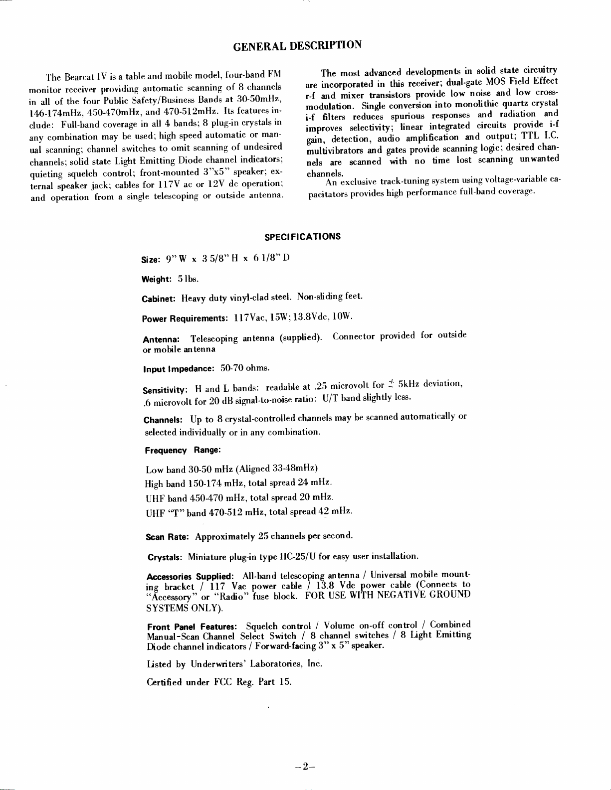
remove
To
tom rear
inet. The components
easily
of
corresponding to its channel.
the
band for each
a particular channel,
position.
position
the third or
mHz)
edge.
accessible.
Up
to
L, H,
or
radio)
The
of the
andooT"
POWER BEFORE
WHILE
OFF
cabinet, first
the
Push
eight crystals may
U/T
bands. Each crystal is installed
eight
three-position
crystal.
(Nearest the
switch selects
o'U/T"
(470-5l2mHz)
rear panel forward
the
and
To
place
the corresponding
front
position
INSTALLATION
REMOVING
INSTALLING
remove
crystal
installed
be
(Channel I is nearest
slide
select
of the radio).
"Hi"
used for
is
bands.
the screw at the bot-
through
sockets are in
in any combination
switches select the desired
"Lo"
Band
(30-50mHz)
switch
The
Band (150-l74mHz) and
both
CABINET
CRYSTALS
cab-
the
full
in the sockets
center
"U"
and
view
the side
in the
"H"
or
(450-470
for
"L"
,,UIT"
Received
frequency - 10.80 mHz =cr1 stal
frequency
I
Example: 453.250
mHz - 10.80 mHz = {9.16llI
mHz
9
USER
man-made
lines, fluorescent
of
etc.
such
of
this
conditions
prevents
channel
HINTS
Radio
equipment
electro-magnetic
lights, motors, appliances,
Modern radios
sources
unusually
Distant
weak,
receiver because of
interrupt
reception
may
are
but
operation
noise.
strong
".hp"
be bypassed
usually
noise which
designed
may be affected
noise
or
high
its
scanning
of other
by
environment
operates
in an
radiates from power
ignition systems,
to minimize
interference
under conditions
may be
signals
sensitiuity.
whenever a
or
Whenever
very
desired signals, the
means
its individual
of
from
received by
such
channel
busy
affected
panel
of
switch.
00 0000 00
t23.1
5878
[il[[[[00
Remove
by
stal
aligning the pins with
down. DO NOT BEND
TURE
WILL
crystals
CRYSTAL FORMULAS
SOCKETS
BREAK OFF
NOTE: Do not
Rigid
by Electra Company
warranty does
from
The
"H"
150mHz to
frequencies
New
'(L'r
"H"
-
crystal by a
the
ARE N,IADE
IF
BENT
install
two crystals
qualiry'
"U/T"
Received
Example:
Received frequency
Example:
standards are applied to crystals furnished
to assure full performance.
not include
other
sources.
alignment
l7[mHz,
may be
frequency
35.80
155.01 mHz
mHz
pull
gentle
the
upward.
sockets and pushing
THE SOCKETS.
OF SPRING
EXCESSIVELY.
of the
correcting
spread is 450mHz
and the
added within
+
10.80
-
3
poor operation caused
"L"
these
mHz = crystal frequency
+
f0.80 mHz
10.80 mHz
-
10.80 mHz
=
=
crystal
3
Insert
the cry-
straight
THESE \'IINIA-
BRONZE
same
therefore our
to ll2mH.z,
33m[z
spreads.
46.600fi) mHz
frequency
=
48.07000
AND
frequency.
to ABmHz.
by
the
ln cases of strong
desirable to
pickup
medium
reduce
below a
and
strong signal
-Single-channel operation
under Operating
with
ing
will
"\IANUAL-SCAN"
the
all but
out
alwavs be
the
on that channel
Continuous-carrier
interfering noise
length of the antenna to
the
critical level.
This
or signals
may be very
areas.
may
be obtained as
Instructions. It may
in either
switch
also
be
position
desired channel. This assures that the
signals
even when
as
such
turned
ESSA weather broad-
the
casls on 162.55mH2, which are available in many areas,
be received when desired by use of
swi
tches.
In mobile
tion conditions
systems,
setting of the
Shen
power
squelch
moring
service the
are signal
lines
or shipping
antenna to avoid damage
commonly encountered
fading, nearhy faulty ignition
proximity
and
control
will minimize these conditions.
the radio, remove
it or to the internal circuit assem-
to
individual channel
the
to strong signals.
the
blies.
RADIO
Locd Govemment
Highway Maintenance
Forestry-Conserration
Motion
Special
Telephone Maintenance
Automotile Emergency Power
Public
Mobile Telephones Forest Products
SERVICES
Pictures
Indusbial
Mobile
Radio
Emergency Police
Specid
-Hospitds
-Ambulances
-Physicians
-Disaster
-School
Peholeum
Relief
Busses Taxicab
Fire
Press
Business
Railroad
Marine
Manufachrers
Motor
Rural Radio
-4-
it may be
noise
reduce
effective
in
described
accomplished
lock-
by
radio
OFF and ON.
may
poor recep-
Careful
telescoping
Carrier
Page 5

ALIGNMENT
I-F
SECTION
Nignment
and balancing
of
the detector
by quartz crystal
tivity.
Field
alignment
l. Connect
2.
3.
4. Detune
5.
I-F
the
filters
and
should not be
Connect
Maintain
prevent
to
T5
Adjust
T3
Adjust T5
for
and
best
system
output. The
"peaking"
consists
necessary
EOUIPMENT
Sweep
generator with 10.79,
and l0.BlmHz
generator
sweep
oscilloscope
output of
distortion
for
for
so
linearity.
lo.
10.B0mHz
from
maximum
maximum output,
that 10.80
8
of
optimizing the input
bandpass and center frequency
the coils can
but the procedure
result
in bandpass ripple or
is
NEEDED
Oscilloscope
10.80
markers
to TP-l through a lpf capacitator.
to TP-3.
generator
sweep
overloading.
IF output display.
mHz is in
Figure 3.
See
and T4
center
at a low level
See
for
minimum ripple.
of discriminator
and output networks
for
given
Figure
general information.
2.
curve
established
are
poor
sensi-
ALTERNATE
Model 800
+
25kc. Markers
The R-F
disturbed.
Factory
test modules,
unique
The
maximum
performance
DESTROYED
Figure 2
METIIOD:
Generator
D() NC)T
are
or
not
essential
ATTEMFT
alignment points
alignment involves
output
indicators
R-F
system inclurles
over a
BY
AN
ATTEMPT TO
to.8l
I-F
alignment may be checked
equivalent
since center frequency
R-F
ALIGNMENT
are adjusted
and training
electronic
wide range
"PEAK
tuned
to an operating frequency
SECTION
"PEAKNG''
OR
and
sealed at the
multi-frequency
beyond
the scope of normal
tracking
frequencies.
of
UP''
"TWEAK''
OR
Figure 3
using a Measurements
and swept
is determined
OF R-F
SECTTON.
factory
by the filter.
and
should
not
be
signal generation systems, add-on
service
of R-F
and oscillator
THIS PERFORMANCE
"OPTIMIZE'"
OR
activities.
circuits for
CAN BE
ETC.
-5-
Page 6

l'4A
33o
49
R
470
c42
.ool
c4/
.ol
a
.|
c2
3.3
Rt6
loK
Rls
33K
D4
ct8
;.;
Rzz
O
R3
33K
*re(c)
"l
t
loo
R5
Z.ZK
R19 5
27Kf
.'i-44
f
R24
loK
+t2 (c)
RzO
56K
DGT
t
f
T
\?.,
ci3
Lrot
czs
.ol
,x,,h^vvc3
=
I
331
Ln +
f
c24 t
47O
vvcs
V22 tll-3
'.'ru
L
R27
22K
I
+tZ
3
c4
.o0
{
O
R56
R57
loK
R55
47K
(C)
+12
RESTSTOR
CAPACITOR
U1{LE33
CRYSTALS
ll-18
sw
VALUES
Y
OTIIERUI9E
Y-I TO Y-8
OHng
ft{
LIIESBELOU
^bvE-
ABovE
SPECIFIED
vll
H
L
I Iil
I lN
R4l
330
c36
.ool
TFD
pl
c
R42
22K
+12
+12
(c)
Ll4
c32
470
R38
33K
R37
loo
| css
* ro
DB
+ toK
C59
.oot
c37
.ool
BEARCAT
rT\
+
T'
€
*
,1u
R54
47K
N
c40
1-
J-
=
R50
K
6.8
R53
4.7 K
SCH
R48
6.8K
R52
loK
|
I
I
!
Page 7

c55
R74
IM
sw3
R65
loK
c56
ool
c 45
.oo 5
Ll5
ll-l-Ilr
-E--=:-:r
. OOI
470K
R75
IM
R88
470
FLI
R66
'oo
FLz
.otuot
FL3
S
Ll6
139
+
c
Dlo
47l
.l
R78
820
c54
.l
+12
c48
.l
R76
IK
*lz
I
c57
.o47
9
tc-
t35
R77
loK
+12
cso
0l
.05
f
?
R79
47K
Ll7
c52
c49
470
cs3
.l
c5l
3.3
T
*
ttu
R80
toK
VOL.
c58
z.zut
.oo33
+
R8l
33K
R,69
loK
c60
l2
toK
c59^
.ol
82
+
13
c6l
IOO MF
6V
Io
+
R86
to
R97
470
R96
22
I
R72
39n_
+
c62
IOOMF
K
R7l
+12
33
c64
too
c
65
.01
R99
56
+12
R84
K
1.5
SQUELCH
R87
5K
K
x'93*
R98
47K
ilo2
t?o
RtoT
2.2M
I
I
4l
t70
Yl AT IC
T6
c69
.05
RtoS
47
0 l/2w
R
tlo
3.3
20h
Rill
5.3
2"h
K
K
+12
A.C.
PLUG
R
to4
47K
RloS
150
l/ 2
+12
V,l
D.C.
sw2
PLUG
Page 8

-8-
=
IJ] F
>a
a.7
OX
F>
s)
Page 9

VOTTAGE CHARI
The Voltage
You
should be
IC
No. I
PIN
Channel
1
2
3
4
5
6
7
8
9
10
1l
t2
l3
t4
No.
I selected.
Chart
familiar
1.4
GND
r.45
GND
11.6
t2
t2
GND
x
x
x
x
x
x
may
used as an approximate
be
with the entire manual before attempting measurements.
INTEGRATED
2 3 4 5 6
1.4
GND
r.45
0
10.5
ll
10.2
0
x
x
x
x
x
x
5.6
3.4
0
1.4
t.4
1.4
GND
GND
.15
1.5
NC
3.4
t2
6.2
guide
in following circuit operation or locating a defective stag
CIRCUIT VOLTAGES
0
6
6
GND
NC
6
t2
NC
x
x
x
x
x
x
8
NC
GND
NC
GND
.6
0
1.3
NC
6.4
NC
t5.2
NC
15.6
NC
5.2
5
NC
.2
5.2
GND
5
.l
t.6
6
5
6
6.2
7
NC
5
.t
NC
.l
5
GND
5
.l
NC
5
5
NC
6.2
8 9
.1
.l
t2
.1
5
t2
GND
.2
5
5
t2
5
.l
5.2
5
5
t2
5
.t
t2
GND
t2
.l
.l
t2
.l
5
.2
logic
The
"
"l
and
movement,
I.
over 4v. I.C.-6
No. PIN
C.
6
7
9
8
LOGIC CHART
sequence for counting is shown
(*)
9
COI.JNT
up or
5
6
8*,
9*
5
6
8
9
8
ll
6
3
3
6
ll
8
pins
8 and
"Manual-Scan"
of
down,
the
I
2 3 4 5 6
0000lltl
llrr0000
rlllllll
00000000
01010101
10101010
r1001100
00ll00tl
0lltllll
l0ltllll
rr0lllll
lllOtttl
llll0lll
lllll0ll
llllll0l
lllllll0
by
change
Switch.
"0"
under .5v
state on each
7
8
TRANSISTOR
TEST CONDITION
L(HUr)
LH/ur
NO XTAL/XTAL..
LH/UT
LUT/H
SQLJELCH,CWCCW
SQUELCH
SQIJELCH CW/CCW
MAN/SCAN
MAN/SCAN
CW/CCW
LHi{n
LUT/H
Q
Ql
2
3
4
5
8
9
l0
ll
l2
t3
t4
t5
r6
t7
l8
l9
20
2l
22
QO
Q7
No.
VOLTAGES
E
2.3
.8
GND
GND
t2.o
t2.0
3.4
.2s
lr.2
t2
lt.7
t2
GND
GND
.007/.0003
GND
014
t2
5.4
5.4
15.6
D
11.8/0
tl
B
3
1.5
.7
0lo7
12.0
I1.0
6.0
t2:0
rt.4
rr.3lrr.6
3.8
.9
rr.9lrr.3
r2lrr.3
.41.7
.7
l.M
.081.7
0
6
t2
6
6
l5
r2.ol0
t2
r2lrr.8
0lt2
0l12
.7
.08/10.s
GND
.0s/4.0
t2
l5
t2
s Gt G2
GND
GND
0
0
c
l.M
6
0
4
01.7
*Tuning
-9-
Voltage - varies
crystal frequency.
with
Page 10

SERVICING
GENERAL
It is recommended that servicing of this
factory
by the
maintained at the
products.
of our
all
When
retuming radio
include
antenna.
include a trrief. detailed description of the difficulty
having.
feafures
conventional
transistors
attempted by anyone
facturer's recommendations and
these
since they
damage semicon duc tors.
tuning
tuning
as
in the
ing
tion
modulation as
tone
decrease to approximatel,v
inteEated circuit from
power
l.6v at 20ma.
polarized
When
the
lampi if not, check
refer
crystals,
Disconnect cables
The receiver circuitry is designed to
four
of
bi-polar
and
devices. The
can deliver voltages and currents
Unusual
channels are scanned.
"L"
antenna
Audio output power
or by measuring
is received. the output
for
The LED indicators have a forward
a
lamp
to the
circuitry
system.
voltages to
band,
circuit.
voice communications.
and
channel lamp
or the switching
losic chart.
center. Special equipment and skills are
service
factory
ac
types of semiconductors:
integrated circuits. Servicing
I.C.
track the
loading coil L-l
shorn
The current
may
to give
receivers
and dc power
transistors, insulated-gate field-effect
who
use of
ohmmeters
in
this
No.1 and
Also, when the receiver is operating
is
the
on an oscilloscope.
overload.
be damaged by a high reverse voltage.
does not light,
I.C. If
I.C. [hen
the
fast
to the
antenna, pack carefully and
and
is not familiar
cautions
is particularly hazardous
receiver
associated
the
antenna, r-f and oscillator
is
switched
measured
maxirnum excursion on
rrill
start
half power
It rrill
not
should
channel n'orks, check
the
groups
receiver be done
efficient service on
and
factory
cables
and telescoping
utilize
rectifier diodes,
should
with the
relating to
large enough
includes
with
at
to
voltage drop
exceed 50ma. They
the
the automatic
circuits
into the
bursls of modula-
S'hen
a
full porver
protect
retum
then
failure
may
lamps are out.
of
for
service,
you
are
the best
not be
manu-
each
generate
circuits
telescop-
voice
continuous
and then
the output
full
to
about
of
are
be either
the
TRACKED TUNING
All tuned
variable
individually
ing is
all
applied
frequencv
justed
volves
to
eren the
should
of
capacitators which
done automatically
parts of
Tracked
to
br Tl.
Facton-
highlv specialized
nornral
Because
onlv
BANDSWITCHING
to
Switches SWll-lB
each channel.
7.8.9) and
three l2\' bandswitch
the
select
ductors
selected
Band Selected
in
channel. the logic diagram is as
H
t-/T
(Qtt)
l. Switches DB on
2. Switches
3.
{. Switches Dl on
5.
(QB)
U
(Ql3) on
l. Switches DB
2.
3.
4. Switches
SYSTEM
in
circuits
regardless of
band without
any
tuning is accomplished
YVCI
and
senice
most highlr- trained
2.3,4,5.6.
.
higher
is
Rl7 and
T2.
alignment
activities.
unique
this
made bv
be
These sn'itches,
hansistor
proper RF
VHF
the
section
I
I
0
BA\DS\\'ITCHI\G FUNCTIONS
for
L/T band only
on
QB
Switches
Q{
-supplies bias roltages to
(UHF Section)
for
on
[,
Supplies drain voltage to
for
Supplies
Gate 2 bias
Switches D5 and D6 on
L9
and Ll
RF sections
the
optimize the
falls
it
where
allows the
and
compromise.
This
for higher
R52.
RF and
of the
equipment
feature is out-side
technicians.
Electra.
used to select
are
the
switches
signals-
section
(VHF or
to select
in any
by
voltage
frequency
tracked
and
channel scanning
Qll,
QB,
U, U,
L or H band.
follows:
0 = OVDC
0
0
I
0
0
I
(Grounds
off
on (Shifts
(Shorts
H band
or
H band only
(Grounds
on
l)
on (Shifts tuning voltage
Q4
I = 12VDCL
Tripler Tank)
tuning voltage upward)
antenna
Ql, Q2, Q3
to
Q7
(Shorts
are tuned
radio
Bearcat
means of a
training
the
and
UHF)
by voltage-
for each
band. This tun-
IV to tune
DC
with
varies
crystals.
tuning
not
experience of
the
adjustments
these
proper
and
Q13
H.
These
and switch in-
loading coil)
(VHF
Q6
Tripler Tank)
(UHF \lixer)
out low
crystal
voltage
crystal
It is ad-
system
in-
available
for
band
logic (IC6,
generate
signals
For
any
amplifier)
coils
band
upward)
-10-
Page 11

Resistors,
...........
33k
............
330
2.2k..........
..........
6.8k
22k...........
..........
3.3k
1k
47k...........
l0K, Var.
.........
8.2k
27k ..........
..........
56k
10.............
68k ..........
4.7k...
15k ..........
470 .........
5.6k
r00 ..........
82
1.8k.........
270 ...........
33............
39 .............
470k .......
Meg.
1
820
10k Vol. w/sw ................
2.2Meg.
l.5k
..........
82k
Var./Squelch
5k
22.............
150 ..........
2.2Meg.
.........
470
3.3k,2Vo
Capacitors
.001mf 20%Disc.
3.3pt
2.2pt 2O% Disc.
ISpt t0%
33pt
20%
27pt l0%
68pf l07o
l0pf
l0%
22pf t0%
!
lpf
6.8pf 5%
100pf
470pt
.Olmf
.02mf
82pf 10%
.005mt 20% Disc.
.05mf
GMV
.lmf
.lmf
l0%
.001mf
.047mf
2.2mf
.0033mf
100mf Lytic 15V
500mf Lytic 10V
2000mf Lytic 20V
lO%
YN
. .......::::::::
.
Contol .
Cer.
Disc.
20%
.25Vo Disc.
l0Vo
2O%Disc.
20%
20% 50V Disc.
50V
Solid Al.
Cer. .......
Cer.
Disc.
Cer. .......
Disc.
Cer. .......
Disc.
Cer.
Disc.
Cer. .......
Disc.
Cer.
Disc.
Cer. .......
Cer.
Disc.
Cer.
Disc.
Cer. ......
Cer.
Disc.
50V
Disc.
Cer. .......
Cer.
Disc.
Cer. .....
10V Disc.
Mylar ......
33V
l0%33V Mylar...
l07o 33Y Mylar...
20% 6V ..
l0%33V
....
.......
.......
.......
.....
......
Cer.
Cer.
.....
Cer.
SERVICE
Price
List
.2s
$
.25
.25
.25
.25
.25
.25
.25
.25
.75
.25
.25
.25
.25
.25
.25
.25
.25
.25
.25
.25
.25
.25
.25
.25
.25
.25
t{
2.00
.25
.25
.25
1.50
.25
.25
.25
.25
.25
.50
.50
.50
.50
.50
.50
.50
.50
.50
.50
.50
.50
.50
.50
.50
.50
.50
.50
.50
.75
.75
.75
.75
.50
1.00
1.00
1.50
PARTS
LIST
rc3
IC4
L-8,
L-9,ll
SP-1
Price
Semi{onductors
2N5179
traps:riq: ...............::::::::
2N4t26
3N201
2N3563
MPS-3640
TIP-30
MPN-3401
1N914
1N34A
6V
lN400l
BB-105A
BB-209
LM-703LN
MC-I357P
'uA74l
UA7O6
sN7474
sN7426
Inductors
A-219-l Loading Coil
A-218-l Choke
A-509 Ctroke
4-508-1 Coil
,{-508-2
l0
A-2184 Choke
B-501-2 Coil
B-5ll
A-218-3 Choke
B-501-1 Coil...........
A-205
A-218-2 Choke
9-502-2
B-502-l Coil
9-217-2 Coil
8-507 Power Transformer
Miscellaneous
A-135 Ctystal
A-226-l
A-226-2 Crystal
P.
B-254-l Man-Scan
GF-124 C.
A-503-l
4-504-1 Contact, SW......
A-505-l
1207 Antenna Connector
1200
3512A
P3304AB
S-3304-FHT-M
DC
AC Cord
Mobile Mounting
8-248-2
A-1 38-2
8-228
C-233Trim........
C-203
A-237 Antenna
RB-155-840
t.l
Zener
(Matched)
(Matched)
.........
Coil
.........
Coil ..........
Choke
(tracking)
Coil
(tracking)
(I.F.)
Crystal
C. Board.
Cord
tenna 1.50
L.E.D. ........ .75
W.
Switch.......
Frame,
Handle,
Antenna
Wrap Assembly ....
Plug .75
Ext.
Speaker
Power
Socket.... 1.00
Assembly 1.50
Assembly 1.50
Speaker 3x5
Telescoping An-
Front Panel
Bushing .
Knob
List
.......
....
..
..
Filter
Filter
Switch
........
SW
..... .25
SW
Jack
Conn. ...
Kit ......
.......... $ 1.75
2.50
.75
.75
2.50
.75
.75
1.50
1.00
.50
.50
1.00
.50
2.00
2.OO
1.50
3.s0
3.50
5.00
2.00
1.50
1.00
.50
.50
.s0
.50
.50
.50
.50
.50
.50
.50
.50
1.50
r.50
2.00
3.50
5.00
10.00
10.00
2.00
.75
1.00
.25
.75
1.00
1.00
2.00
3.00
3.00
7.50
.75
.75
Electra
C.o. - P.
Replacement
O. Box
29243,- 300
order for
Cash
parts
may be ordered directly
S. County Une
parts
will be shipped
-11-
Rd.
-
prepaid.
from:
Cumberland,
Ind.
46229
Page 12

RETURN WARRANTY
NOT
DO
ABUSE
OR MODIFY
CARD WITHIN
RADIO
IO
DAYS
This receiver
We
aEee
to remedy
under
normal installation,
is
delivered
to our factory,
provided
This
accidents, incorrect
instructions
factory.
our
to us,
such
examination
warranty
furnished
within
NEVER
is
guaranteed
such
intact,
one year from
does not
wiring
by us, nor
REMOVE
to be
defect
or to
use
and
for
our examination.
discloses,
not
apply if
our
to receivers
in
own;improper
A SERIAL NUMBER
WARRANTY
free
from
defects
furnish
service,
our
the
a new part
discloses
rrith
the date
judgment,
receiver has
that
of sale
have
in
material
in exchange
such defect, provided
alt transportation
to
the original purchaser,
that it
is thus
been
subjected
installation,
been
repaired
for
defective.
or
to
and workmanship.
any part which,
the receiver
charges prepaid
and
to misuse, neglect,
use
in
violation
or
altered
outside
of
This
warranty
shall in
the purchase
no
TO PT,ACE
MTHrN
IM-501-l
TEN
excludes
event
be
liable for
price
of the
WARRANTY
(10)
DAYS
all oral
damages
alleged
defective
IN FORCE
OF PURCHASE.
ELECTRA
()F'
[)l\'1.\l(
)\
300 East
Cumberland.
or other
for
a breach
equipment.
FILL
\l
\S(.( )
County
Indiana,16229
implied
warranhes,
warranty
of
OUT AND
CO}IPANY
(.(iRP(
)tt
Lint
Rd..
South
and the manufacfurer
in
RETURN
)\
\'l'l(
an amount exceeding
WARRANTY
CARD
-t2-
 Loading...