

Electra Bearcat BC3-L, Bearcat BC3-H, Bearcat BC3-L/U, Bearcat BC3-H/U, Bearcat BC3-U Operating Instructions Manual
...Page 1

Page 2
GENERAT
DESCRIPTION
The
FM monitor
band
channels
Bearcat
III is a table
rectiver
in one or
Bands at 30-50mHz,
features
Its
modules;
r-f
high
used;
switches
Emitting Dode
Iight
sensitivity
arrd
external
speaker
include:
plug-in
B
speed
to omit scanning
control;
jack;
motile
and
providing
of the three
two
L4,6L74mHz
and
provisions
crystals
automatic
channel
in any
or manual
undesired
of
indicators;
front-mounted
for ll7Yac
cables
Size: 9"W
Weight:
Cabinet:
Power Requirements:
Audio
tones).
Output:
External
model, single
automatic
scanning
Public Safety/Business
450-47OmHzfor
one or
two
combination
scanning;
channels; solid
comtination
x 5" speaker;
3"
or l2Vdc
x
35/B"H
operation;
x
5lbs.
Heavy duty
vinyl-clad
ll7
W rms, voice
3
speaker
connector
Vac, l2
dual
or
of B
plug-in
be
may
channel
state
squelch
SPECI
61iB"D
steel.
and
The
incorporated
are
and
r-f
modulation.
filters
i-f
improves
gri;,
multivibrators
nels
channels.
FICATIONS
Non-sliding
l3.B
Vdc,6
protected
W;
(Power
provided.
operation
detection,
are scanned
from
most advanced
mixer transistors
Single conversisr
reduces
selectivity;
and gates
feet.
W-
at
a
in this
spurious
audio
with
W on
1.5
tele*oflng
singfe
developments
receiver;
provide
into
responses
inteEated
linear
amplification
provide
time
no
continuous
in
dud-gate
ncise
low
monolithic
and
scanning
lost
oqtjde
c
state
solid
\lOS
and
guartz
radiation
and
circuits
output;
desired
logic;
scanning
antenna.
circuitry
Field
low
provide
TTL
unwanted
Effect
cro$s-
crystal
and
i-f
I'C'
chan-
Antenna:
mobile antenna
or
Input
Sensitivity:
deviation,
Channels:
be scanned
Frequency
f,ow band
High band
UHF band
Telescoping
lmpedance:
H and
microvolt
.7
Up to
iutomatically
Range:
*30-50
xl46-L74
450-470
50-;0
B
(*Factory-supplied
supplied'with'
special
Scan
request.)
Rate:
Crystals:
150-f74
Approximately
Miniature
Accessories Supplied:
bracket
ing
"ficcessorv"
SYSTEMS
Panel
Front
Manual-Scan
channel
Dode
by Underwriters'
Usted
Certified
I
or
ONLY).
Features:
Channel
indicators
under
iI7
"Radio"
FCC Reg.
antenna
(supplied).
ohrn-..
L bands:
for 20
crystal-controlled
mHz, total
mHz,
dB
or selected
spread
total
mtJLz, total
alignment
f9t [,ott band
mHz alignment.
channels
25
plug-in
All-band
Vac
type
power
HC-25/U
telescoping
cable
?use block.
Squelch
Select
/
control
Switch
Forward-facing
Laboratories,
Part
15.
Connector
readable
at
signal-to-noise
channels
individually
mHz.
15
mHz.
spread
spread
24
20
mHz-
is
Other
per
second.
easy user installation.
for
antenna
Vdg
t3.g
/
USE
FOR
Volume
/
channel
B
/
3"
x
5"
Inc.
for
for
t
slightly
band
bands)
two
combination.
High
available
are
mo^bile
microvolt
.25
ratio:
(in
one or
or
3348
alignments
Universal
/
provided
U
in any
mFrz.
pgwe_t_9ahl_e-(Connects
B
/
Light
GROUND
Combined
Emitting
WITH
on-off
switches
NEGATIVE
corrtrol
/
speaker.
outside
kHz
5
less'
-aY
band is
on
mount-
to
-2-
Page 3
INSTALLATION
This
receiver
accessories for
in
areas
of
whip
antenna
If
an
outside antenna
you
may
use
antenna for
U models
the
using
only. External
receiver
the
supplied
antennas are
MOBI
LE INSTALLATI
is shipped
mobile
fair-to-good
supplied, may
a l55mHz
L and
by
50 ohm coaxial
available
INSTRUCTIONS
complete
or
table use.
rip"l strength,
be used
is necessary
antenna
L/H
models
antennas
automotive
at most radio
ON
cable,
type connector.
fu a fixed receiver
on all bands.
for
on
all bands.
or a 4.6&nHz
should be coupled
zuch
dealers.
with
the
the
telescoping
fringe
antenna
as RG-58 A/U,
necessary
reception.
a 40mHz
on
to
Suitable
noise
The
other
areas
is
too
parts
of low
lengthy
generated by the
car is
of the
signal strength.
deal with adequately
to
It is recommended for
with the
book" or
subject to
"The
purchase
Mobile
Radio Relay [,eague and
further
It is
vice center
communications
OPE RATI
recommended that
which
specializes
equipment for correction
ON
auto electrical
sometimes
a problem, particularly
The subject of noise elimination
in
instruction book.
this
who wish
those
"The
Manual" published
by most
sold
the
in VHF-UHF
to become
Radio Amateur's
by the
electronic
vehicle be
parts
taken to a ser-
two
noise problem.
of a
system and
in
familiar
Hand-
American
stores.
way radio
This
receiver
having
In
receive police
of this radio
ization
be responsible
l.
2.
3. Insert
4. Attach
5. External
\-OLT
a l2
some areas it
is responsible
throuch
Plaee
hold
\lark
:H:
inrt-ard,
secure the receiver
and
two
"accessory"
above.
extended
duced
mav
be installed
\EG
{TI\E
is
illegal for
communications
for
local
agent-ie5
for
anv
illrgal
the motile
the receiver in
and drill
the bracket with
the
in
U4"
the DC power
mobile
The
for
to approximately
mounting
two holes
plastic
two
the desired pair
in place
ID
x
9116" OD flat
"radio"
or
antennas
automotive
L,
H
in anv car.
GROU\D
unauthorized
on
a mobile
obtaining
ap6l Electra
installation
bracket under
the
desired position.
using
the
two
"T"
washers,
of mounting
with
cable
terminal
may
antenna
or L/H
models.
18" for
truck.
SY-ITE\I.
receiver.
any necessary
Conrpanr
usage.
or
a 7164
the
washers.
and connect
be used
U models.
No.
6
flanges
two ll4-20
on
the
may
be
It
drill
self-tapping
fuse
as described
should be re-
boat.
etc..
persons
The
user
author-
cannot
the dash
bit
and
turned
holes
and
bolts
it
to
block.
used
fully
the
\\ith
l.
to
2.
to
the porter
turn
the receiver
conrol
Place
Set
clockwise.
the B channel
the
Adjust
rushing
control
cable and antenna properly
O\ by rotating
switches in
"\IA\UAL-SCA\"
"SQUELCH"
the
noise
heard.
is
counterclockwise
control
Then
until
connected,
"VOLUME"
the
the up (ON) position.
switch
adjust
"MANUAL".
on
clockwise until
"SQUELCH"
the
the rushing noise
the
dis-
apPears.
Press
continue
should
the
to quiet
TWEEN
The
6.
to
7.
To
UAL-SCAN"
be
switch
select
sample
omitted
"MANUAL-SCAN"
the
to step
"break
squelch
through all channels.
the
squelch"
control counterclockwise
the receiver.
STATION
TRANSMISSIONS.
"MANUAL-SCAN"
and monitor
channels
all
any desired
switch to
desired
as
by moving
downward (offl.
switch
on any channel,
THIS MUST
switch
may now
channel.
automatically,
"SCAN".
Any
the individual
downward
If
again
BE DONE
return
the
channel may
and
noise
the
adjust
slightly
BE-
be used
"MAN-
channel
-3-
Page 4
CRYSTAL
INSTALLATION
DISCONNECT POWER
LEAVE
To
bottom
cabinet.
view and
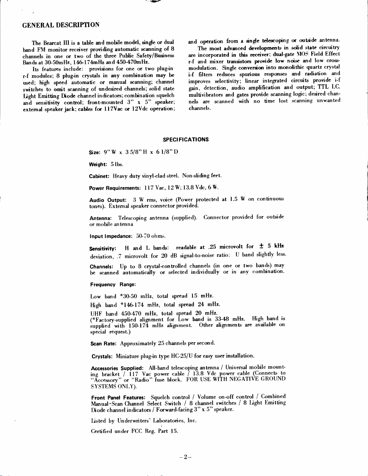
Ihe three
No.
crystal
outside row.
nearest
one outside
used.
inetalled
be
crystal frequency
which it
POWER
remove
rear
edge. Push
The
easily
l. The
will be
them
row
A
total
in
is connected.
OFF WHILE INSTALLING
the catinet,
components
accessible.
crystal
second
$n
row
inetdled
Ihe
outdde rows
on the
will bc-used
eight
of
ary order and in
is proper for
BEFORE
first remove
the rear panel
and
crystal
sockets
betrpen
oppodte
crystals
at the
of 3 ie
connect
dde of
wheNr only
may
either burd
the
REMOVING
the
forward
sockets
front
are
for
channel
the centcr
to
the
the boerd. only
one r-f
be used.
as long
particular
CABINET
CRYSTALS
screw at the
through the
in full
are
for
channel
2 etc.
row
Each
and sre
r-f
module
module
They may
as each
module
is
to
6'L:'
USER
man-made
lines, fluorescent
etc.
such
of unusuallv
this receiver because
conditions
prevents
channel
switch.
Reecived frequ€ncv
Example:
453.250
HINTS
Radio
equipment usually operates
electro-magnetic noise which
lights,
Modern.
sources but
Dstant
radios
are designed to
operation
noise.
strong
"rhp''
weah
intemrpt
reception
ma,v
be bypassed by means
-
10.80 mHz = crystd
9
-
mllz
10.80 mHz = 49.16111 mHz
9
motors,
or
its high
of
scanning or
of other desired
appliances, ignition
minimize interference
may
be affected
noise
siErals
sensitiuity.
whenever
frequency.
in an environment of
under
be
Whenever
very
busy
from
power
systems,
from
conditions
received by
such
channel
affected
panel
radiates
may
a
signals, the
its individual
of
I
I
l(on
L,
H
or U modules may
Remove
crystal
the
straight
down.
MINIATURE
WILL
AND
NOTE:
by
our
Do not install
Rigid
quality
Electra
warranty
caused by crystals
Unless
450mHz
the
within
"L"
to
33mHz
these
crystal
the
by
aligning the
DO NOT
SOCKETS
BREAK
standards
Company
does not
from
ordered
470mHz,
to
spreads.
OFF
otherwise
4BmHz. New
CRYSTAL FORMULAS
'6H"
"L))
Received frequency
Example:
155.01
Received frequency
Example:
35.80
CRY
STA L S
tll
E
TODUL
RF loDuLE'B'
eorror
trDE
Figure
by
a gentle pull upward.
pins
with
BEND
ARE MADE
IF
BENT EXCESSIVELY.
two crystals
are
applied
to assure full
include
other
sources.
the
6'H)'
the
-
10.80
3
mHz - 10.80
*
fdgO -H,
mHz + f0.80
cn vsrrue
roDuLE
\
nF toouLE
be in
I
the sockets
THE
SOCKETS.
OF SPRING
of
the
to crystals
performance,
correcting poor
"U"
150mHz
frequencies
mHz = crystal frequency.
mHz
mHz
position.
either
and
BRONZE
frequency.
same
furnished
therefore
operation
alignment
spread
to l7$mHz,
may
be added
=
48.07000 mHz
=
crystal frequency.
=
46.60000
I
I
't'
Insert
pushing
THESE
is
and
mHz
The
squelch control
in addition,
comes a
weak
strong
channel
desirable
pickup
medium
under
with
ing
will
Continuous-carrier
casts
be received
switches.
tion conditions
systems, power
setting of
antenna
blies.
RADIO
Local Govemment
Highway Maintenance
Foresty-Consenation
Motion
Special Industrial
TelephoneMaintenance
Automobile Emergency
Public
Mobile
sensitivity control.
signals or
signals.
may
In
cases
to reduce
below
and
Single-channel
Operating Instructions.
"MANUAL-SCAN"
the
out all
but
always
be
on 162.55mH2,
ln
mobile
the
When
moving
to
avoid
SERVICES
Pictures
Mobile
Telephones
-4-
functions
it
as
is rotated counterclockwise
By careful
can
be adjusted to receive only medium or
Interference
be reduced
of strong interfering
the
critical
a
strong
riprl ane:rs.
operation may
desired
the
on that channel even
signals
which
when
desired
service the commonly
are
signal
lines
and
squelch control
or
shipping the radio, remove
damage
Radio Petroleum
from
in
this manner.
length
of the antenna
lerel.
switch in
channel.
such as the
are available in
by use
fading,
proximity
will minimize
it
to
or
Emergency
Special
-Hospitals
-Ambulances
-Physicians
-Disaster
-SchoolBusses
Power
Forest
Products
in
normal manner and,
the
setting,
weak
signals on the
noise
or
signals
This
mar tr
be
obtained
It
may
also be
position
either
This
assures
when
turned
ESSA
many
of the individual
encountered poor
nearby
to
shong signals. Careful
these conditions.
to the internal
Relief
farther,
to reduce noise
ven- effective
accomplished
that the radio
OFF
weather
faulty
the telescoping
circuit
Police
Fire
Press
Business
Railroad
Taxicab
Marine
Manufachrrcrs
Motor
Rurd Radio
it
can
it
accept
same
it may
as described
by lock-
and ON.
broad-
areas, may
channel
recep-
ignition
assem-
Carrier
be-
be
in
Page 5

ALIGNMENT
I-F
SECTION
Alignment
and balancing
by quartz
tivity. Field
crystal
alignment
l.
2. Connect
3.
4.
of
the I-F
the detector
filters
and
should
Connect
Maintain
prevent
to
Adjust
ripple.
system
rot be
Sweep generator
sweep
oscilloscope
output of
Tf and
See Figure
consists
output.
"peaki.g"
necesqan-
EOUIPMENT
and
generator
distortion
T2
The
Oscilloscope
l0.BlmHz
tO.BmHz
for
2.
lo.8
t o.8l
of optimizing
bandpass and
the coils can result
but the procedure
NEEDED
with
10.79,
10.80
markers
to TP-l through
to
TP-2.
sweep generator
from
overloading.
maximum output,
the input
center frequency
in
bandpass
is
lpf
a
at a
and minimum
and output networls
ripple
for
given
general
capacitor.
low
level
are established
poor
or
information.
sensi-
-{LTER\ATE
\lodel
+
25kc. \larkers
disturbed.
test modules,
maximum
DESTROYED
800 Generator
DO
NOT
The R-F
The unique
performance
Connect
is in center
See ligure
METHOD:
are not essential
ATTEMPT
alignment
Factory
alignment
output
indicators
R-F
system inclurles
BY
AN
over
ATTEMPT
Figure
2
scope
to
;in
of discriminator
3.
I-F
alignment
or equivalent
since
R_F
ALIGNMENT
points
are adjusted
involves
and
training
electronic
a wide range
TO
"PEAK
TP-2
and adjust T3
curve
and
may
be
tuned
multi-frequency
to an operating
eenter frequency
SECTION
"PEAKING''
OR
and
sealed
beyond
of frequencies.
the
tracking
UP'' OR
Figure
3
so that l0.BmHz
for
best linearitv.
checked
at the factory
signal
scope
of R-F
THIS PERFORMANCE
"TWEAK''
using
a Measurements
frequency
is determined
OF R-F
generation
of normal
and oscillator circuits
MODULES.
and
systems, add-on
service activities.
"OPTIMIZE'.
OR
and
swept
by
the filter.
should not
CAN
ETC.
be
for
BE
-D-
Page 6

J3
Rf
,r3
@t
,12
ctol
220
1D
cloz
-
+ lvvc
ctoS
Llol
C
lO.l
.ool
66
Tj;X"l
LzOffd
R
toz
loo K
R
to6
tooK
illo;o,:b"T
{'.+
T
=
Rao6
looK
-oaot
lr,n t
22O
BOARD 30-50
n
cros-
=
ct09
'.ool
L
tOZ
llol
Rill
33K
O
t02
l=ll I llx
Rros:.Gf-
toof.ol
BOARD
H
-Tceoa I
caoz
+i
9i-ot
MHz
J5
l-F
il
146-
Lzg
ff
o3
=t
Lt
-rlt.tH
crrs
r
+6oR!43
MHZ
174
R2l4
toox
J7
Rt22
t50
FCll'
l.ool
ldrg
DZOI
r^TrLz?l
L
lo6
c2t9
I
ANT.
J6
+to
t
A
t-8
c201
.ool
R302
J3
l6K
o-+?:3,
,12
R-F
35x
*
.I
206
oo
c306
.oot
t:*l
VALUE
RESISTOR
cAPAcrroR
UNLE
t....t
CHA}IOE
TAY
VALUES
VALUEr
SS OTHERUISE
B OARD
L3O3
IX OHII'
itr.r?? i
45O
0{3
0302
R306
4rx,.
T
cslo
to
*:;1.
il
ilt
SPECIFIED
I
c2t6 T I
56
-
47O
J5 I-F
R
lo8
too
R3ll
53K
xTALS:J4
J
I-
{
HZ
M
R309
33K
c3lz-T-csr
R
3t3
t6K
_
*:tI
azzz
RSlO
l.5l(
s
Rzla
L207
L
30G
L507
toK
+lo
c320
t.7-6
J6
rf6
+to
i Y---T= -
1 ) lsos
LL_18
A.C. PLUO
R32
2.21
ll2v
317
R
too
R43
2.2K
D.C. PLU(
43
t: n
lsozu
--J€
2
4
I
;-]
4:
c5n
PL-I
[
I
3
[
[
-
SCHEil
Page 7

P=A
-ttt+1
P4f6q
-l
i
\rl.Bto,
TI
:I
t=
fro
.O.+?
)F-l
C6=
.o47
7F
*-^a1
SOUELCH
Rll
5K
L4
h
.4P
RI
6'2K
Rlo
56K
L5
.4r h
c9
T.l
FL2
c36
MFD
2
+to
+lO
i|
=
R46
22
ctz
.ool
RIz
loK
Rl7
33X
+to
toTq
v
13)t
g
Rl9
l.6K
cts
.l
14;
L6
ct6
g
c33
.o
c2l
.o2
2rTK
.o2
ol
+
+!o
c.1
3
f
-:-
too
lr+
-J
c'|7
.o+z
4.7K
Rt8
YO
K
L.
c22
25TFD
l5v
,4
2K
c3l
.oot
D9
p__
1t
t---.-J
Dto
3
c30
2000
20v
c35
IOOTFD
t5v
6I
lrco
UFD
D8
llv
t2
I
l-
,14 llt
o9
+lo
,?.
C 34
.or
*
+
6l2l
--ll'[l- -l
I
I
'lr -*r Ll,
t4
+to
lrcrl
19
l;?
8lt2
I
1u 1,.
R22
4.7
lo.,'
R27
1TK
K
R26
33K
R.t7
toK
c26
300
R2t
E.ZK6o/c
+t4
3V
xFD
R21
too
C25
CZ+
47O.oo5
'83,h
gc
AN
I
su2
IA}IUAL
ATIC BC
Itr
Page 8

c30
20oo
roor;r{
!
i@,tl
ffi
*^.{'.f"
#
A
t!
Y
x€
cu3
ftft-rL
ue
;rnnnn1ffp;
+i-tu +
-ffi*.
ffi,r,
-e$i'f.
&{e*il,
;#4tryl:
\:'r'A:u*.r"-6
}r:'.lif
lfr,,g,,'"
i
J"''"'
#'#
.d:i
&*
MFD
rs
t'
I
+;
I
.gA
l
sig
I
I
lg,h
lrl lri
VY
(#5
RF
@
paa
#m6i
ul
€'
db
t;
, ',,
,
I
,
_r #til,-
-€):y$?i
-.uTghsffie-iqtl+^
*ri,fi#
&Do*t\9H-
ff_sfp't.
H
l:',,"
*.6nu'*'
"A
***".
ri
F"
o
-E;
;,$u
ggry-$;,a*T
"ifli
-PsA
"ifif.
Itll
w,"*'
Main Board
View
Top
ffi
ffiLih*F
,:g,:ft
\
ono
*3
!,g.P;
lu.
.P
q..'1
a:l_.P
*um*fuu
,g;H
F'
s
ift ^
o
x
n
LO BAND
3 L MODULE
Top
View
HI BAND
MODULE
H
3
Top
-8-
@
View
805
c
[t
"tEtaaot[stCFA
1--zZ
F.F
i.,[*€H
UHF BAND
MODULE
U
3
View
Top
Page 9

'l'he
\'oltage
delet:tive
stage.
Ohart
You
may
[rt' usetl
shoultl
VOLTAGE
as an approximate
familiar
be
with
the
CHART
guide
t:ntire
in followingcircuit
manual bel'ore
attempting
operation orl<xratinga
measuremt:nLs.
+l
*2
+iJ
+4
t5
t6
;
tI
9
103
t0-1.
203
20,1
303
30+
;JO;
306
|0l
r02
201
202
;t()
|
.Jt)l
GND
G\I)
GND
GNT)
0
r0.2
4.01.9
(;NI)
l r.0
:i.0
7.-1,
1.9
.(r
9.6
1.9
6.9
.15
rf.2
r0.2
r0.2
|0.2
10.:J
().b
.2lO
01.2
.41.6
7lo
l0.l
5.8
.ir
l 1.5
,f
.(r
r0.0
.J.6
9.9
10.3
3.+
5.5
.i5
o/:t.2
I
3.2/0
|
|
|
|
I
I
|
I
|
I
.7lo
.tll/tt
+.tt7.,1
.;
;.tt
16.0
lO..l
e.6
to.z
| 9.6
|
I
|
|
tO.:l
ltt.:l
I o.z
t).0
0
0
0
0
o
o
PI\
\0.
I
l
r.6
T]NT)
2
;l
1.4
rt
NC
l0
lt
NC
6
t.6
7
N(l
tI
()
t0
ll
tl
tiJ
l4
Voltages
ntanual position.
".itluelt'
2 l
:1.(r
3.5
NC
I
.-1
I
.:1,
1.4
GNT)
CNI)
.l:1.
I
.rt
NC
3.5
l0
;..J
are
lt'' cou ntercloc k n'ise
\
t.C.
GNT)
GNT)
measured
"\'olunre
ti\ilJl
l3
\(l
9.1
.7
.5
NC
0
N(l
.ir
7.9
0
lIr
It
4
N(l
4.-1
5.0
1.5
.l
4.4
GNt)
4.4
.l
1.4
6.2
,1:4
5.5
6.2
rvith
"
t'ontr<ll courttert'lockw-ise
e\cept:
I-r 6
NC
5.0
.l
NC
.l
5.t)
GND
s.0
.l
NC
5.0
5.0
NC
6.2
"\lanual-Scan"
ir.0
5.0
9.0
ir.0
9.0
(;\t)
9.0
9.0
ir.0
.l
.l
.l
.l
.l
switch in
a
.l
.l
9.0
.l
5.0
9.0
GNT)
.2
5.0
5.0
9.0
5.0
.l
4.1
anrl
l.(l.
\o.
PI\ l 2 3 {
,lr
0000tttl
6
{
;)
(
(t
lllt0000
{f*
ltlttttl
()*
00000000
;)
0l0t0l0l
6
t0101010
tf
lt00lt00
00ll00lr
9
t|
0ttlttll
rOttlttl
n
6
rl0lltll
j]
ttl0llll
;t
tlllOtll
6
tlllt0ll
l r
tl
{l
rlrllll0
COUNT
;)
I | |
(l
I 0. l
#
Stluelch
Scanning/\lanual
t
Crystal operating
*
tl
logic
The
.5v and
each
mov€ment,
"l"
sequence
over 4v.
up or down, of the
con
LOGIC CHART
for counting
I.C.-4, pins
trol
C\\'/CC\l'
A/B
on
B &
side
is
shown
(*) change state on
9
"Manual-Scan"
by
"0"
Switch.
under
Page 10

SERVICING
It is recommended that servicing of this
factory
by the
maintained at the
all of our
include
antenna.
include a brief.
having.
features
conventional
transistors
attempted
facfurer's recommendations
these
since
damage semicon
products.
When
returning
crystals,
Disconnect cables and
The receiver
four
of
bi-polar transistors,
and
by anyone
devices. The
can deliver
they
SERVICE
center. Special
service
factory
to give
fast
radio receivers to the
ac
and dc
power cables and telescoping
antenna,
detailed description of the
circuitry
types
integrated
is designed
of semiconductors:
circuits. Servicing should
is not
who
and cautions
use of ohmmeters
voltages and currents
duc tors.
PARTS LIST
receiver be
equipment
efficient
and
factory
pack carefully
difficulty
utilize
to
rectifier
insulated-gate
familiar
is particularly
with the
relating to
large enough to
done
and skills
service
for
service,
)'ou
the
diodes,
field-effect
not
manu-
each
hazardous
are
on
and
are
best
be
of
Unusual
tuning system
circuitry
in the
I.C.-201 and the
to
scanned.
manner.
loading
coil
"U"
The
Also, when the
[,-1 is switched
the antenna,
track
circui t.
output
Audio
measuring
by
or
tion
modulation
tone
decrease
integrated
po$-er
The
l.6v
polarized
as shown
is received,
approximately
to
circuit
voice communications.
for
indicators
LED
and
The
may
at
20ma.
When a channel
lamp or
the
lamp;
refer to the
the switching
not, check the
if
logic chart.
in this
o'f,"
associated
r-f
and
is broadbanded
"Ll'
is measured
power
the
an oscilloscope.
on
the output
half power
from overload.
have a
current should
be damaged
not light, the
does
lamp
I.C.
I.C.
receiver includes
"H"
and
modules.
circuits generate
oscillator
module
circuits
in
is
into the
more conventional
a
operating,
telescoping
with bursts
maximum
excursion
When a
full power
will start
at
to
protect
It will then
forward
voltage
not exceed
high
by a
failure
If
channel
the
When groups
the
tuning
as channels
the
of
continuous
the
return
drop
50ma.
reverse
may be
works,
lamps
of
automatic
I.C.-101,
voltages
are
antenna
antenna
modula-
voice
on
and then
output
full
to
of about
They are
voltage.
either
the
check
are out,
Ref. No.
(pRrcES
SUBJECT'l'O CHANGE
MAIN
BOARD
Resistors,
Capacitors
mf.
.001
mf.
.01
.O47mf
mf. GMV
.l
3.3pt
.02mf. 20%
.22mf
l50pf 20%
.l0V
25mf
I 00pf 20%
l00mf. 3V
500mf.
.047mf.
2000mf.20V
l00mf.
35V
2mf.
WTTTTOUT
t/+W
lOTo
Disc. Cer. ............
20%
Disc Cer. ................
20%
Disc. Cer. ...........
GMV
.
Disc. Cer.
Disc. Cer.
lO%
Disc. Cer. ...............
Mylar.
.10%
10V
l5V Lytic..
Cer.
Disc.
Lytic..
Cer.
Disc.
Lytic....
Lytic..
Mylar.........
Lytic..
Lvtic.........
NOTICE)
List
................
................
Price
.50
.50
.50
.50
.50
.50
.50
.50
1.00
.50
1.00
1.00
.50
1.50
1.00
.15
Semi-Conductors
F.
.........
2N3563
MPS3393
C.
Mot.
.........
List
2N3640.....
T.I. ...........
TrP-29
I\+ I +8......
rN3+A.......
5%.............
IN524lB
llV
rN400l
LM703LN
SN76643N
T,4.-61lC
Nat. ..........
ULN2I
or
S.G.S.
I I A......... 4.00
sN-7474....
sN-7426....
Emitting
Light
A-259
Inductors
A-219-1
A-218-l
A-205-l
A-261
B'-217-2I.F.
B-2O2PowerTransformer..........
Miscellaneous
A-135
(Frequenciesasrequired)...........
Slide
Antenna Connector
Antenna
PowerConnectorP3304AB.......
LoadingCoiI.......,.........
RF
Choke..
RF Choke..
RF
A-218-2
A-226
8-254"Manual-Scan"Switch.....
Ext.
Power Socket
Cord Assembly...
DC
AC Cord
\Iobile
8-248 Speaker
A-138-2TelescopingAntenna....
8-228
C-233
C-203WrapAssembly.....'..........
A-237AntennaBushing.............
Knob RB-I55-840.......
Choke..
Coil.....
Crystal
Crystal
Switch,
Plug
Speaker
Jack
Assemblv...
\lounting
Pane1.........
Front
Trim..........
Diode.......
Fi1ter.........
SPDT.....
No.
1200..............
No.
No. 351
FHTM...... 1.00
5-3304
Kit.................
x
5" 3.2
3"
1207....
2A.....
ohm.
Price
.75
.75
.7
1.50
.50
.50
1.00
.50
1.50
5.00
2.00
1.00
1.50
1.00
.50
.50
.50
.50
2.00
3.00
5.00
10.00
2.00
.7b
.7b
.7
1.00
1.00
1.50
1.50
2.00
3.00
1.50
l '7
3.00
7.50
.75
.75
5
b
5
Page 11

SERVICE PARTS
(Continued)
LIST
Resistors.
V+W
l0%
List
Price
Price
List
mf.
I
.00
I mf.
.0
6.8pf
56pf l0% Disc. Cer.
Semi-Conductors
3N201 r.r.
2N3563
2N3640.....
I N34A.......
LM703LN
Disc.
2OTo
2OTo
l0% Disc. Cer.
Ccr..............
Disc. Cer.
..............
................
.................
........... ..
F.C.
.......... .75
Nat........... 1.50
.50
.50
.50
.50
2.50
.7
.50
Inductors
ts-208-3AntennaCoi1...............
4'-218-3 RF
8-208-4
,\-218-2 RF
B-22O-l Osc.
Choke..
RF
CoiI...... 1.00
Choke..
Coil 1.00
B-209-lTrackingCoil..............
A-218-l
Resistors,
RF
Choke..
V+W. lO%
1.00
.50
.50
1.00
.50
3.3k........... .25
15k............
.25
22k............ .25
{.7k ..........
68k............
.25
.25
100............ .25
33k............
330............
1.5k...........
10k............
k..............
I
.25
.25
.25
.25
.25
5
C;rpacitors
3.3pf l0%
I .7-6pf
l5pf l0% Disc.
22opt 20%
.00lmf.
.0lmf.
l0pf l0% Disc.
5pt 5% Disc.
68pf 5% Disc. Cer.
27pf
I 5pf l0% Disc.
l00pf
47Opf
5pf
Semi-Conductors
3N201 T.r............
2N3563
MPS-3393..
Inductors
A-221-lAntcnnaCoil...............
4.-218-4 RF
A-221-2 RF
A-218-2 RF
8-220-2 RF
A-218-l
A-218-3 RF Choke..
Disc.
variable......
Disc.
2O%Disc.
20% Disc.
Cer.
lO% Disc.
l0% Disc. Cer.
Disc. Ccr.
20%
Disc.
l0%
Cer.
F.C.
..........
Choke..
Coil.....
Chokc..
Coil......
RF Chokc..
Cer.
...............
Cer.
................ .50
Cer.
..............
Cer.
..............
Cer.
................
Cer.
..........
Cer.
Cer.
.................
................. .50
.50
.7 5
.50
.50
.50
.50
.50
.50
.50
.50
.50
2.50
.75
.75
.75
.50
.7 5
.50
.75
.50
.50
Electra
co.
Replacement
-
P.
o. Box
29243 - 300
order for parts
Cash
parts
may
be
s. count-v Line Rd.
rvill
orrlere<l
be
shipped
dire ctll'
-
cumberlancl,
prepaicl.
from:
Inrl.
46229
Page 12

RETURN
WARRANTY
CARD
WITHIN TO
DAYS
NOT ABUSE
DO
NBVER REMOVE
This receiver is guaranteed to be
We agree to remedy
under normal installation,
is
delivered to us, intact,
to our
provided
accidents, incorrect wiring not
instructions furnished
our
factory, within
such examination discloses, in
This warranty
factory.
does
defect
such
use and
for
one year
not
by us, nor
apply if the receiver has been
MODIFY
OR
A SERIAL
WARRANTY
free
from defects in material
fumish a new
or to
service,
examination,
our
from
our own;improper
receivers
to
discloses
the date of sale to the original
judgment,
our
RADIO
NUMBER
part
in exchange for
defect,
such
with all transportation
it
that
is thus defective.
subjected to
installation,
have
that
been repaired or altered
or to
workmanship.
and
part
any
provided
the
charges
purchaser,
misuse,
use in violation of
which,
receiver
prepaid
and
neglect,
outside
This warranty excludes
in no event
shall
purchase price
the
PLACE WARRANTY IN FORCE FILI,
TO
MTHrN
TEN
be
of
(10)
tNI-201-2
all oral
liable for
the alleged
DAYS OF
VISIO\
DI
300
or
other implied
damages
defective equipment.
for
a breach of warranty in an amount
PURCHASE.
ELECTRA
OF
East
Cumberland,
\,IASCO
County
Indiana
COMPANY
Line Rd., South
warranhes,
AND RETURN
OUT
CORPOR
16229
\1'I0\
ild the
manufacturer
exceeding
WARRANTY CARD
-r2-
 Loading...