

Electia CS185, VT30CT, VR50E, UR81SCT User Manual
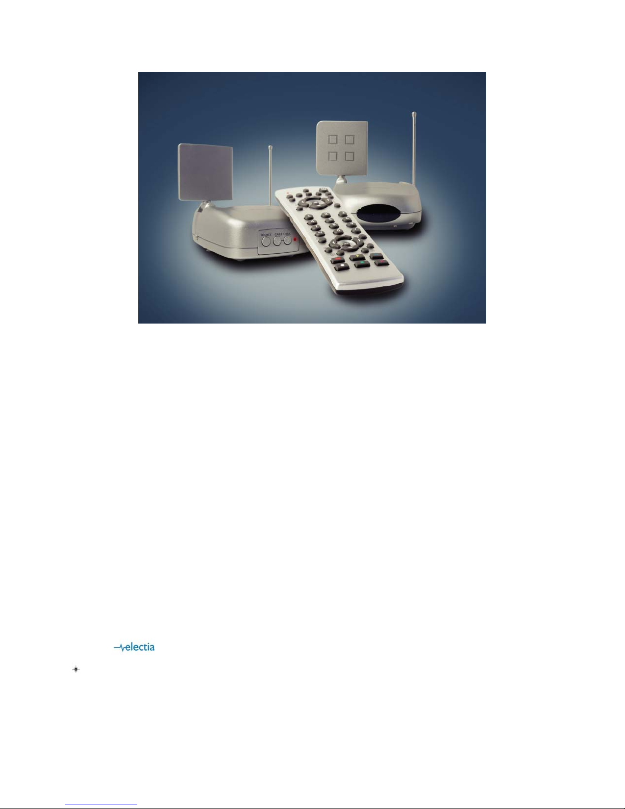
Cable sender CS185
Transmitter VT30CT and Reciver VR50E
5 in 1 remote UR81SCT
UK User guide
SE Användarmanual
FI Manuaali
Modell/Malli: CS185
Art: 38.1655

ENGLISH
Thank you very much!
You have acquired an electronic system with a very high technical standard. With the VT30CT Video Transmitter you can transmit
colour images with stereo sound through walls and ceilings.
Please take care to read the installation and operating instructions before starting.
Please read this manual even if a third party has already installed the system because it contains important information and basic
principles of operation.
We would not expect any problems to arise with the system but if any should occur please inform the dealer from whom you bought
this device.
Please keep these instructions ready to hand whenever you may need to consult them.
Contents
1. Safety Instructions ........................................................................................................................................
2. General description.......................................................................................................................................
3. General functions .........................................................................................................................................
4. The VT30CT Video Transmitter ....................................................................................................................
5. The VR50E Video Receiver ............................................................................................................................
6. The 6in1 IR control for the CableLink ...........................................................................................................
7. Programming the CableLink .........................................................................................................................
8. Starting up remote control - for TV only ........................................................................................................
9. Installation with extra A/V equipment............................................................................................................
10. Operating possibilities...................................................................................................................................
11. Changing the coding of the remote control...................................................................................................
12. Rectifying a malfunction................................................................................................................................
13. Technical data ..............................................................................................................................................
1. Safety Instructions
IMPORTANT
If the system is handled incorrectly there is a risk of injury from electric shock. The following instructions must be followed, in order to
avoid any risk of injury or damage and the operating instructions must also be adhered to.
. It is not permitted to open the plug’s mains adapter
. Only a properly qualified technician is allowed to check and inspect the system.
. The system is only to be operated in dry indoor rooms.
. Avoid high atmospheric humidity and extreme ambient temperatures.
. Should any fault occur in the power supply the system should be taken out of operation at once. Never replace defective
. If there is any danger of a thunderstorm, it is a good precaution to unplug the power supply from the mains network in
. Power must be supplied at the correct rating at all times. This applies in particular to the operating voltage in the system
. If there is ever any malfunction, the dealer from whom the system was bought must be asked to send it back to the
2. General description
Correct and proper use:
. The VT30CT Video Transmitter is designed for use in dry indoor rooms. The electrical power is provided by the mains
. Please only ever use this mains adapter. It is not permitted to alter or modify any part of the system.
. The unit is registered as a device that does not cause or suffer from radio-frequency interference. It is CE approved and it
. The safety and installation instructions must be observed.
. There shall be no guarantee cover against damage resulting from any failure to observe these operating instructions and
3. General functions
This kit includes an A/V sender and receiver. It transmits any audio video signal anywhere in the house, without any extra cable.
Cable transmission
Thanks to the cable turner integrated in the transmitter, you can watch one cable channel on your main TV, and another cable
channel on a second TV.
Multi-source
With this kit, you can also transmit an audio / video signal from any A/V source: Cable, SAT, DVD player, VCR, TV... to another
appliance such as TV, VCR... You can select and manage the source remotely by the supplied remote control
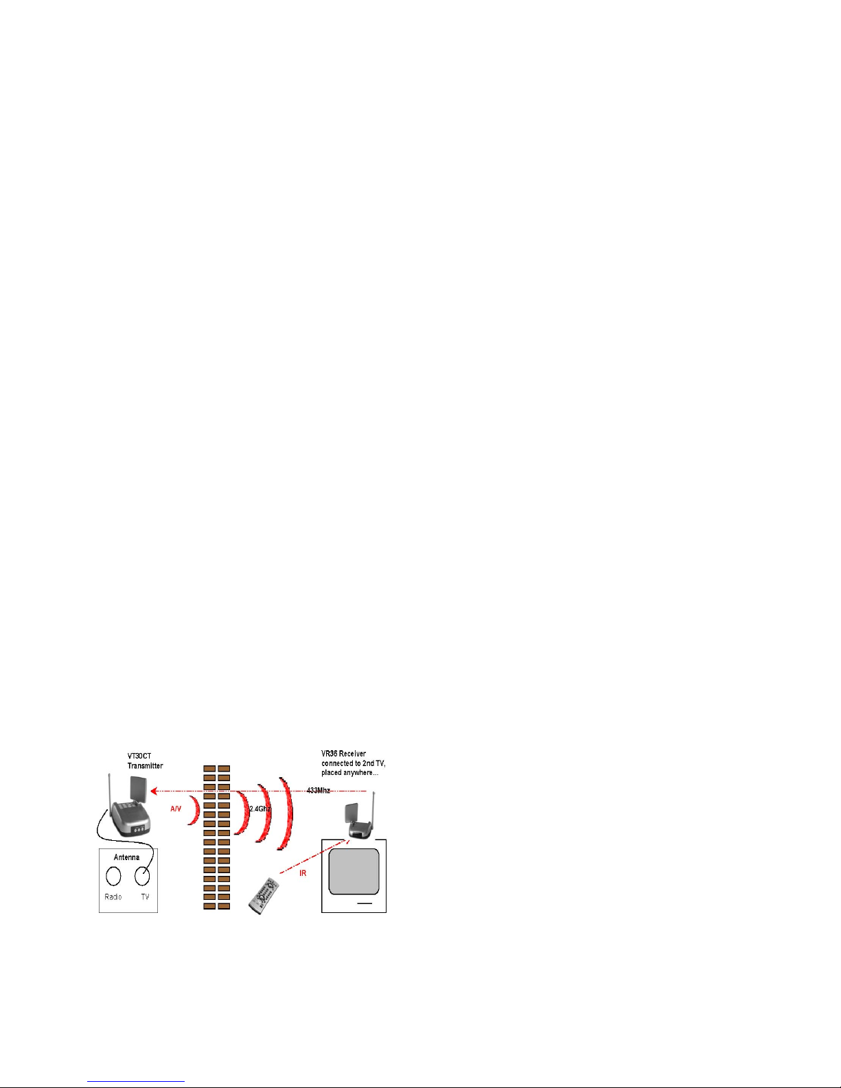
How does this work ?
The audio and video signals are transmitted at 2.4 GHz by the VT30CT Video Transmitter to the VR50E Video Receiver. The
maximum line-of-sight range is 100 metres. The signals of the 6in1 remote control (included) are transmitted by radio at 433 MHz
between the VR50E receiver and the VT30CT transmitter.
parts with anything other than original spare parts.
order to protect it from lightning. The same applies if the system is to be out of action for any length of time.
and the mains adapter.
manufacturer for inspection.
adapter included with the transmitter.
conforms with the Low Voltage Directory.
no legal liability for any resultant consequential damage.
4. The VT30CT Video Transmitter
Items included:
1x CableLink Video Sender VT30CT 1x 12Volts adapter 1x infrared extender cable with 3 LED’s
RCA cable 1x SCART / RCA adapter labelled sender
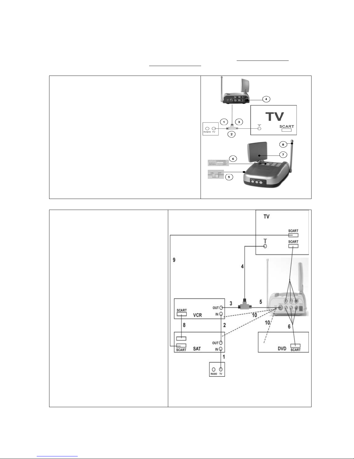
Installation of the transmitter without extra A/V equipment: Direct
transmission of cable channel from the antenna wall socket only
1.Insert the T plug into the antenna wall socket.
2.Connect the original antenna cable to the T plug on one end, and to
the TV antenna output on the other end.
3.Connect the coaxial cable (provided) to the cable input of the
VT30CT.
4.Insert the power supply into this input. Plug the adapter into a
standard 230 volts socket.
5.Switch on the VT30CT. The LED will also light up.
6.Channel switch: 4 channels (A,B,C or D) are available. It allows to
connect up to 4 independent systems.
Select the same channel on the transmitter as the receiver.
7.2.4 GHz transmitting antenna: Point the transmitter antenna towards
the receiver
8. 433MHz antenna: Lift the antenna up to vertical position.
The video transmitter can also send pictures from several A/V
appliances linked into series. Please read section 9.
Installing the transmitter with extra equipment
(such as a satellite receiver, VCR or DVD player)
This setup allows you to watch all sources both in the
main room and the second room.
1. Connect the antenna splitter to the aerial connection
of your TV (4)
2. Connect the supplied coaxial cable to one side of the
antenna splitter (5)
3. Connect the other end of the coaxial cable (5) to the
antenna input of the transmitter.
4. Connect the existing coaxial cable from your satellite
receiver or VCR to the other end of the splitter (3)
5. Connect the audio/video output (6) from your DVD
player to the audio/video input of the transmitter. An
RCA/RCA cable is supplied.
6. Connect the audio/video output of the transmitter to
the audio/video input(scart) of your TV. To make this
connection, you can use the cable you originally used
for connecting your DVD to your TV.
7. Insert the plug of the infrared extender cable to the
output (10) on the transmitter. Locate the small IR
LED’s on the IR sensors of the equipment connected.
The IR emitters have a piece of adhesive tape on the
back. Remove the protective label and press the emitter
lightly to the front of your equipment. You may have to
make some adjustments to find the right location
8. Select a channel using the Channel Selector slide
switch (a-d) use same channel to the receiver.
9. Connect the larger power adapter (12V) to the
transmitter. Attention: The power adapters for the
transmitter and receiver are different!
10. Switch on the unit with the ON/OF switch.
11. Make sure the transmitter is placed some distance
away from others items. Do not place the transmitter on
top of you audio and/or video equipment. Direct the flat
2,4 GHz antenna at the receiver.
(to be used in section 9) 1x co-axial T-plug 1x co-axial cable
(to be used in section 9) 1x double
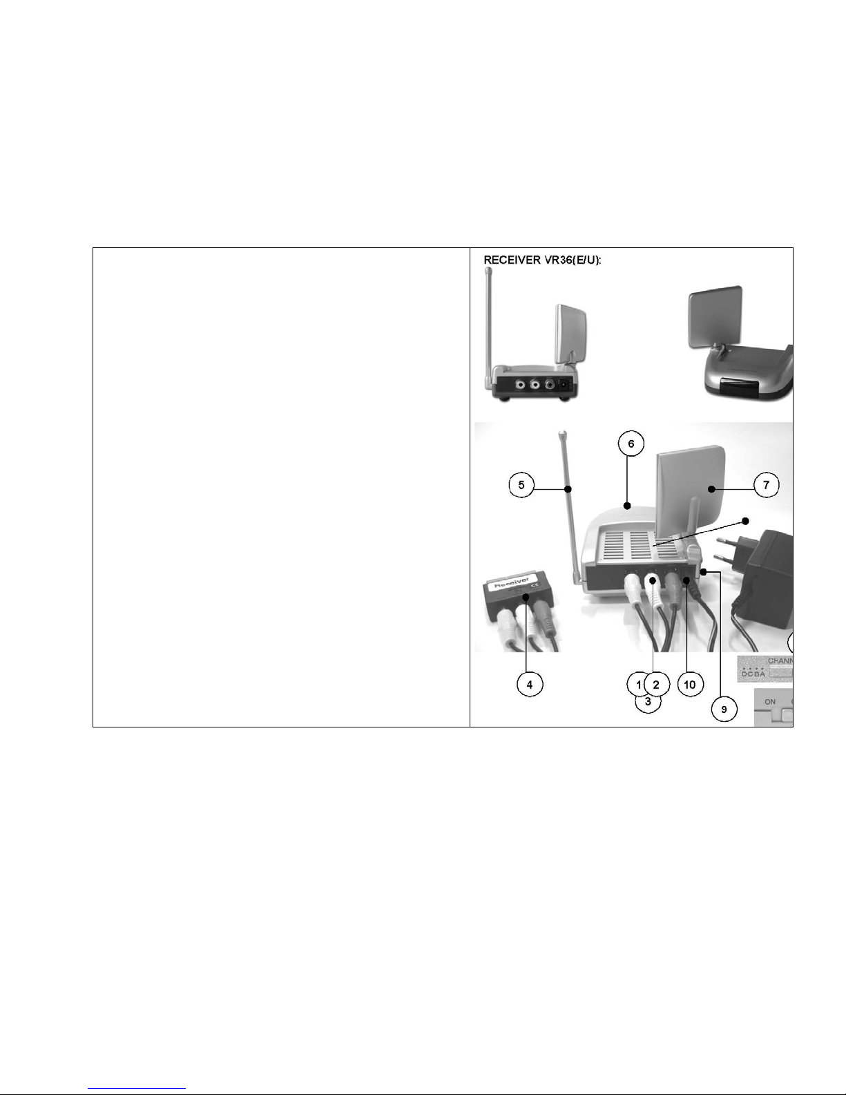
5. VR50E Video Receiver
Items included:
1x VR50E Video Receiver
1x 6V plug-in mains adapter
1x RCA cable
1x SCART adaptor labelled “receiver”
Installation of the receiver:
1.2.3. Plug in the RCA cable: Insert one end of the RCA cable into the
respecting to match the colours.
4. Connection to the TV: Insert the other end of the
RCA cable into the SCART adaptor.
5. 433 MHz antenna: Lift the antenna up to vertical position.
6. IR lens: When pointing the 6in1 remote control toward the IR
7. Receiving antenna: Point the receiver antenna towards the
transmitter.
8. Channel switch (under the receiver): 4 channels (A, B, C or
D) are available. It allows you to connect up to 4 independent systems.
Select the same channel on the receiver as the transmitter you wish to
link.
9. Power switch: To switch on / off the video receiver.
10. 6V input: Insert the receiver power supply cable into this
input.
input connectors of the receiver,
Plug the whole into your TV.
lens, the receiver will convert the signal info into 433 MHz,
transmit it to the sender, through its 433 MHz antenna. (refer to
section 7) The sender will receive the message via its 433 MHz
antenna, transfer it as an IR order to the IR emitter eye, and then
the right appliance will operate (refer to section 9).
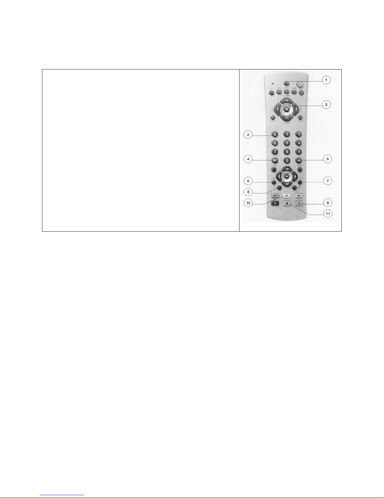
6. Infrared remote control unit for the CableLink
General: You need the 6in1 remote control to control the CableLink.
Control Elements:
[1] CBL: selects the CableLink
[2] 0 -9 : direct TV channel selection
[3] Channel +/-: for paging up and down through the cable TV Channels
[4] Prev. CH: for switching back to the channel last selected
[5] CATV/AV: for switching Video signal (SAT or VCR) and cable TV channels
[6] PASTE (TEXT ON): Adds the TV Channel from the “clipboard” to the current
position in the list after first pushing up the current channel and those above it. The
TV Channel on the “clipboard” is then removed from it’s old position in the list . The
TV screen shows the new channel with “ADDED” superimposed on the picture.
[7] COPY (TEXT OFF): Copies the current TV Channel Number to the internal
“clipboard” so that it can be moved to another position in the list. The screen will
display “COPIED. READY TO MOVE”
[8] DISP: Displays the selected mode : Channel number or “A/V” mode depending of
the selected source (integrated tuner or other external appliance)
[9] SCAN: automatic search tuning for TV and cable TV transmitters (to start the
automatic search tuning press “SCAN” twice)
[10] CH DEL (PLAY) : Delete cable TV channels. To delete a channel, select the one
you want to delete, such as No. 30 and press “CH DEL“. “TV30 DELETED” will
appear in the screen. Next time you page through the channels, No. 30 will no
longer appear.
[11] SET: To change the security code of your
remote control. Use this function if you
have several Cable links at home (see
section 12).
7. Programming the cable tuner
The Cable Tuner is like your TV. It needs to scan and find the available channels. You program the CableLink using the infrared
remote control unit (via the VR36).
1. Switch on the television set to which the VR50E is connected and select the video input (AV) (5) .
2. Switch on the VT30CT Video Transmitter and the VR50E Video Receiver.
3. The television set will display either a blank screen if it’s a fresh VT30CT , or the current channel if it’s previously been set
4. Channel Search: press “Scan” (9) display shows “press again to confirm” press “Scan” again within 4 seconds
5. Display shows “ scanning pls wait” and a barchart to show the progress of the scan.
6. Automatic scan is conducted , approx. 6 minutes
7. Display will then show “ scan complete” – “found XYZ channels”, then TV will switch to the first of the found channels
8. With the channel + and the channel – (3) button you can browse the found channels
9. To delete channels, press the “CH DEL“ button (10)
10. You might be able to improve the quality of a ‘weak’ channel by pressing the FINE TUNE + or -buttons to manually adjust
Rearranging the Channel List
CHAN+ and CHAN- can be used to move through the Channel List. This can also be done by keying the Channel directly using the
0-9 Keys on the handset .
Whenever a channel is found who’s quality is poor or is not a real video channel and needs to be removed from the list, the CHAN
DEL (PLAY) key can be used to do this. After pressing CHAN DEL the screen displays the channel number and ‘DELETED’ is
superimposed on the picture. The old channel is then erased from the list and the list rearranged to fill the gap. Initially the tuner still
shows the old channel, but after 4 seconds it re-tunes to the next channel up and this becomes the new Current Channel.
It’s not necessary to wait the 4 seconds before pressing another key however. The unit will respond instantly to any subsequent key
press, so if you use CHAN DEL and then follow it immediately with CHAN + you need to be aware that although the screen still
shows the channel you have just deleted, internally the unit has already replaced it with the next channel in the list , so an immediate
CHAN + will appear to move up two channels from the one you had just deleted after the 4 sec. has elapsed .
You can alter the order of channels in the Channel List using the COPY (TEXT OFF) and PASTE (TEXT ON) keys.
COPY copies the Current Channel to an internal Clipboard and marks the channel on the list for deletion once the contents of the
clipboard have been pasted into the selected position. Subsequent COPY operations just put the new channel onto the clipboard,
mark it for deletion after use and ‘un-mark’ the previous channel.
up.
the setting. Step through to the channel using the Channel + or - keys and press Fine Tune + or-until you get the best
picture. If you want to save this setting for future use just press COPY then PASTE . The ‘old’ setting will be replacd in the
list by the new one .
PASTE adds the channel on the clipboard to the Channel List at the current position, pushes up the channels above and deletes the
selected channel from it’s previous position on the list. It then remembers that the clipboard has already been used so that the
channel on the clipboard is only erased from the list the first time it is used.
8. Starting up the remote control – for control of TV - VCR - SAT -DVD
8.1 Introduction
The remote control will control your various appliances (TV -VCR- SAT - DVD) and the integrated CableLink (CBL). It is preprogrammed in the factory for most brands and models. Simply enter the code for your equipment and your remote is ready to use
8.2 How to install the batteries
1. Push the tab of the battery compartment on the back site of your remote, and lift the cover.
2. Install two fresh AAA batteries, taking care to match the + and -marks in the battery compartment.
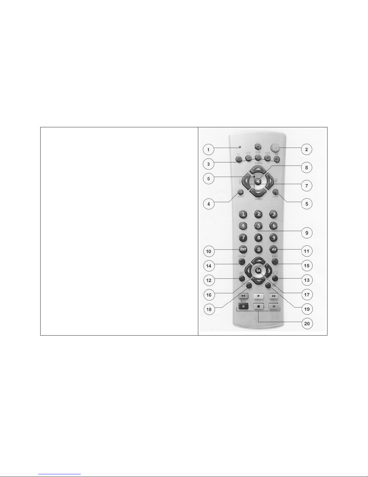
8.3 Button Descriptions:
[1] Indicator light (LED): The indicator light flashes when the remote is
operating.
[2] Power: Works in the same way as your original remote
[3] TV, VCR, SAT, DVD: Used to select the device to control.
[4] SET UP: Used for entering code numbers matching your audio/video
appliances
[5] Shift: To access to secondary functions of your A/V equipment
[6] Channel+/-: Selects the next or the previous channel. Works like
your original remote.
[7] Volume: To adjust the volume. Works like your original remote.
[8] Mute: Turns ON and OFF the volume. Works the same way as your
original remote.
[9] 0 - 9: Used as your original remote and to enter device codes.
[10] Ent (Enter): Used in conjunction with the numeric keys for direct
channel tuning. In set-up mode used to confirm.
[11] A/V: To select the SCART input.
[12] Teletext ON. = PASTE
[13] Teletext OFF. = COPY
[14] Menu: Displays the Menu for the adjustment of colour and sound
[15] Exit : Menu OFF
[16] Navigation keys: To navigate the Menu
[17] OK: to confirm a choice in the Teletext
[18] Info: Displays the channel number. Works in the same way as your
original remote.
[19] Teletext HOLD. Holds the current page.
[20] Play (=CHAN DEL), FF, Stop, Rew, Pause, Record: Works the
same as on your original remote.
8.4 Setting up to control your A/V appliances : TV, VCR, SAT, DVD
1. Turn on the device you wish to control.
2. Press and hold SETUP (4) key until the LED indicator lights steadily. Release the SETUP button.
3. Press and release the mode button that matches the device you want to control : TV, VCR, SAT, DVD (3)
4. Enter the 4 digit code from the Library code tables. The LED turns off after the last digit entered.
5. Point the remote at the device and press the POWER button (2). Your device should turn off.
6. Turn your device on and press CHANNEL+ (6) . If the device responds, set-up is complete. If some buttons do not operate
your equipment, perhaps there is another code for your brand. Please use “CODE SEARCH” (8.5) Note: If the device does not
respond, try the other codes for your brand. If it still doesn’t respond, try the Code Search method. If the LED blinks rapidly when you
enter the code, you may have entered an invalid code. Recheck the code in the code list and try again.

8.5 Manual code search:
When your device cannot be found in the code list, or your device doesn’t respond to any of the codes you entered, you can try to
find the code you need by using the ‘searching for codes’ method:
1. Turn on the device you want to control.
2. Press and hold SETUP (4) until the LED indicator lights steadily. Release SETUP button.
3. Press the mode button (3) that matches the equipment you wish to control. The LED blinks once.
4. Press CHANNEL+ (6) repeatedly until the device to be controlled changes channel. If you go past the code accidentally
5. Press and release the ENTER button (10) to complete the set-up.
Note: You may have to press CHANNEL+ many times (50+). If the device does not have a Channel Up function, use the PLAY
button (VCR or VCR only) or the POWER button.
8.6 Automatic code search:
When searching an unknown code, you can step through the library automatically (AutoSearch). When your equipment responds,
you can stop the searching process and store the code you found.
1. Turn on the device you want to control.
2. Press and hold SETUP (4) until the LED indicator lights steadily. Release SETUP button.
3. Press the mode button that matches the equipment you wish to control. The LED blinks once.
4. Press CHANNEL+ (6) once. After a few seconds the remote starts stepping through the code library (fast search). When
the device responds, you press CHANNEL- to switch to slow search. You can step back by pressing CHANNEL- (you can step
forward by pressing CHANNEL+ in case you went too far back). As soon as the device responds again, press ENTER to store the
code you found.
8.7 Identifying codes found using the search procedure:
1. Press and hold SETUP (4) until the LED indicator lights steadily. Release the Set-up button.
2. Press the mode button (3) that matches the equipment you wish to identify. The LED blinks once.
3. To find the first digit, press each number button from 0 to 9 until the LED blinks (9) . The number you pressed is the first
digit of the code.
4. Press each number button from 0 to 9 as above to find the second digit.
5. Press each number to find the four digit. When the four digit has been found, the LED will go out. Write down the found
code on the label of the battery compartment.
8.8 Trouble shooting
The remote won’t control your equipment, or doesn’t work at all
• Use manual controls or the original remote control to confirm the equipment is working properly.
• Be sure you pressed the device key (TV, VCR, SAT or DVD) for the device you want to control.
• Try finding the code for your equipment using manual or automatic code search methods.
• Check that the batteries have the correct polarity position.
• Replace the batteries.
9. Installation of the Transmitter with extra A/V equipment (e.g. Satellite, DVD, etc.)
1. Connect the antenna box to the Sat antenna input
2. Link the SAT antenna output to the VCR input using a co-axial cable
3. Link the VCR antenna output to the T plug with a co-axial cable
4. Link the T plug to the TV antenna input
5. Link the T plug to the antenna input of the transmitter
6. Connect the audio/video output of your DVD player, with the RCA / SCART adapter (included), to the audio/video input of
the Transmitter - lower row of sockets
7. Connect the audio/video output of your Transmitter to one of the audio/video input of TV
8. Connect one of the audio/video output of SAT to one audio/video input of the VCR
9. Connect one of the audio/video output of SAT to one audio/video input of the TV
10. Insert the infrared extender into the input of the Transmitter. Stick the LEDs on the IR receiver of each A/V appliance you
10. Operating possibilities (page 10)
The VT30CT Video transmitter is able to transmit AV signals over a distance of up to 100 metres (line-of-sight). Any wall or concrete
ceiling will represent a slight obstacle and thus will reduce the transmission range of the system.
Parallel operation of a number of VT30CT Video transmitters (page 10)
• A VT30CT Video Transmitter can be extended with a number of VR36 Video Receivers.
• The various different channel settings (1 to 4) enable up to four Video transmitters to operate in the immediate vicinity of
one another.
Extension possibilities with the VT30CT Video transmitter (page 10)
press CHANNEL -(6) to step back (for first step push button twice).
wish to control To finish the installation of the Transmitter, refer to section 4.

11. Changing the coding of the remote control unit
The basic setting for the code is “0636”. To operate the VT30CT Video Transmitter you need the 6in1 infrared remote control unit
included within the system. NOTE: it is only necessary to change the code of the 6in1 remote control unit if another VT30CT Video
Transmitter is being operated in your immediate neighbourhood (within about 100 metres). To avoid switching your neighbour’s
Video Transmitter TV on and off, you can set a code on the 6in1 remote control unit and at the VT30CT Video Transmitter.
Please proceed as follows:
• Connect the VR50E Video Receiver to the television set to which the cable signal is to be sent (chapter 5).
• Press “SETUP” (located on the left top corner) until the LED stays on.
• Press “CBL” (1)
• Enter the four-digit code (there are only four possible codes: 0636 –0639)
• Turn on the TV (AV channel) and the power supply in the VT30CT Video Sender. You now have 30 seconds to press and
hold down the SOURCE and CHAN^ keys on the front of the VT30CT .
• After around 3 seconds the following on-screen shot will appear:
HANDSET CODE ABC
PRESS “SET” TO CHANGE OR
ANY OTHER KEY TO CONTINUE
• Press “SET” (9). The following screen shot appears:
PRESS AGAIN TO CONFIRM
• The screen shows the following screen shot: CODE XXXX ACCEPTED (e.g. code0636 is accepted)
• Test the connection by pressing “CHANNEL” + or “CHANNEL -” (3).
12. Rectifying a malfunction
Problem Remedy
Poor transmission 1. Reflections of the signal can sometimes affect the
quality Move the Video Transmitter or Receiver away just
2. Change the channel settings (A to D) set on the
Video Receiver.
No transmission 1. Is the same transmission channel (A to D) set on
2.
3.
Remote control channel 1. If you operate wireless headphones or a similar
2. Is the RX cable inserted into the VT30CT and
Infrared remote control
does not
control the VT30CT
transmission quality.
a few inches and this should solve the problem.
Video Transmitter and the
the Video Transmitter and on the Video Receiver?
Is the transmission distance too great? Reduce the
distance between the Video Transmitter and the
Video Receiver. The range is up to 100 metres
line-of-sight, but walls and ceilings reduce it.
Have you used the right cable?
wireless transmitter on the same frequency as
your 433 MHz system, this can severely reduce its
range.
glued over the infrared eye of the unit that is being
controlled?
1. Wrong code set. Reset the code as described in
section 11.
 Loading...