

Electia CTC-909B User Manual
x
C-Fence Home
- with image verification

Table of Contents
1. Application Overview __________________________________________________________ 1
1.1. Identifying the parts _______________________________________________________________ 1
1.2. Insert GSM/GPRS SIM Card _______________________________________________________ 2
1.3. The Power Supply ________________________________________________________________ 2
1.4. How to Install the Control Panel_____________________________________________________ 2
1.5.Two – Level Passwords _____________________________________________________________ 2
1.6. Getting Started ___________________________________________________________________ 3
2.Configuring Your System _______________________________________________________ 4
2.1. Gen Settings (General Settings) _____________________________________________________ 4
2.1.1 Code Settings __________________________________________________________________________ 4
2.1.2 Master code ________________________________________________________________ ___________ 6
2.1.3 Panel Setting ___________________________________________________________________________ 7
2.1.4 SMS Header __________________________________________________________________________ 11
2.1.5 SMS Keyword ________________________________________________________________________ 11
2.1.6 Devices +/- ___________________________________________________________________________ 11
2.1.7. Walk Test ____________________________________________________________________________ 22
2.2. Spc. Settings ____________________________________________________________________ 22
2.2.1. Supervision __________________________________________________________________________ 22
2.2.2. Latch Selection _______________________________________________________________________ 23
2.2.3. Remote Controller Entry Enable Select (RC Ent E) ___________________________________________ 23
2.2.4. GSM Band Select _____________________________________________________________________ 23
2.3. Reporting ______________________________________________________________________ 24
2.3.1 Tel. Settings __________________________________________________________________________ 24
2.3.2 MMS TEL/E-MAIL/FTP ________________________________________________________________ 24
2.3.3. MMS Setting _________________________________________________________________________ 25
2.3.4 GPRS Settings ________________________________________________________________________ 26
2.4. GSM ___________________________________________________________________________ 27
2.4.1 GSM Signal __________________________________________________________________________ 27
2.4.2 GSM Reset ___________________________________________________________________________ 27
3 Operation ___________________________________________________________________ 28
3.1 Entering User Menu ______________________________________________________________ 28
3.2. Away Arm Mode (Alarm ON) _____________________________________________________ 28

3.2.1 Away Arming the System ________________________________________________________________ 28
3.2.2. Stopping the Exit Delay _________________________________________________________________ 29
3.2.3. Extend the Exit Delay __________________________________________________________________ 29
3.3. Home Arm ______________________________________________________________________ 29
3.3.1. Home Arming the System _______________________________________________________________ 29
3.4. Timer __________________________________________________________________________ 29
3.4.1. Time ________________________________________________________________________________ 29
3.4.2. Date ________________________________________________________________________________ 30
3.4.3. Year ________________________________________________________________________________ 30
3.4.4. Daylight _____________________________________________________________________________ 30
3.5. Bypass _________________________________________________________________________ 30
3.6. Forced Arming __________________________________________________________________ 31
3.6.1. Arming the System via Control Panel ______________________________________________________ 31
3.6.2. Arming the System via Remote Controller __________________________________________________ 32
3.6.3. Arming with Door Opened ______________________________________________________________ 32
3.6.4. Arming with IR Triggered _______________________________________________________________ 32
3.6.5. Arming with Supervisory Fault ___________________________________________________________ 32
3.6.6. Arming with MMS Transmission _________________________________________________________ 32
3.7. Alarm Off Mode _________________________________________________________________ 33
3.8. Event Log ______________________________________________________________________ 33
3.9. Interaction Between C-FENCCE HOME and CTC-852 ________________________________ 33
3.10. Alarm Activation _______________________________________________________________ 35
3.11. Stop the Alarm and Alarm Display ________________________________________________ 36
3.11.1. Stopping the Alarm ___________________________________________________________________ 36
3.11.2. Alarm Memory ______________________________________________________________________ 36
3.12. False Alarm Management ________________________________________________________ 37
3.12.1. Dual-Ply Entry Warning _______________________________________________________________ 37
3.12.2. Mis Operation Reporting _______________________________________________________________ 37
3.12.3. Sequential Verification Reporting ________________________________________________________ 37
3.13. Faulty Situations ________________________________________________________________ 37
3.13.1. Fault Message Display _________________________________________________________________ 38
3.13.2. Clearing Fault Message Display _________________________________________________________ 38
3.13.3. Viewing/Clearing the Fault Message ______________________________________________________ 39
3.13.4. Fault Event Response _________________________________________________________________ 39
3.13.5. Fault Message Nomenclature ___________________________________________________________ 41
3.14. Remote Commanding ___________________________________________________________ 41

4. Appendix ___________________________________________________________________ 50
4.1. Device Naming __________________________________________________________________ 50
4.2. Reset Procedure _________________________________________________________________ 50

1
3
1. Application Overview
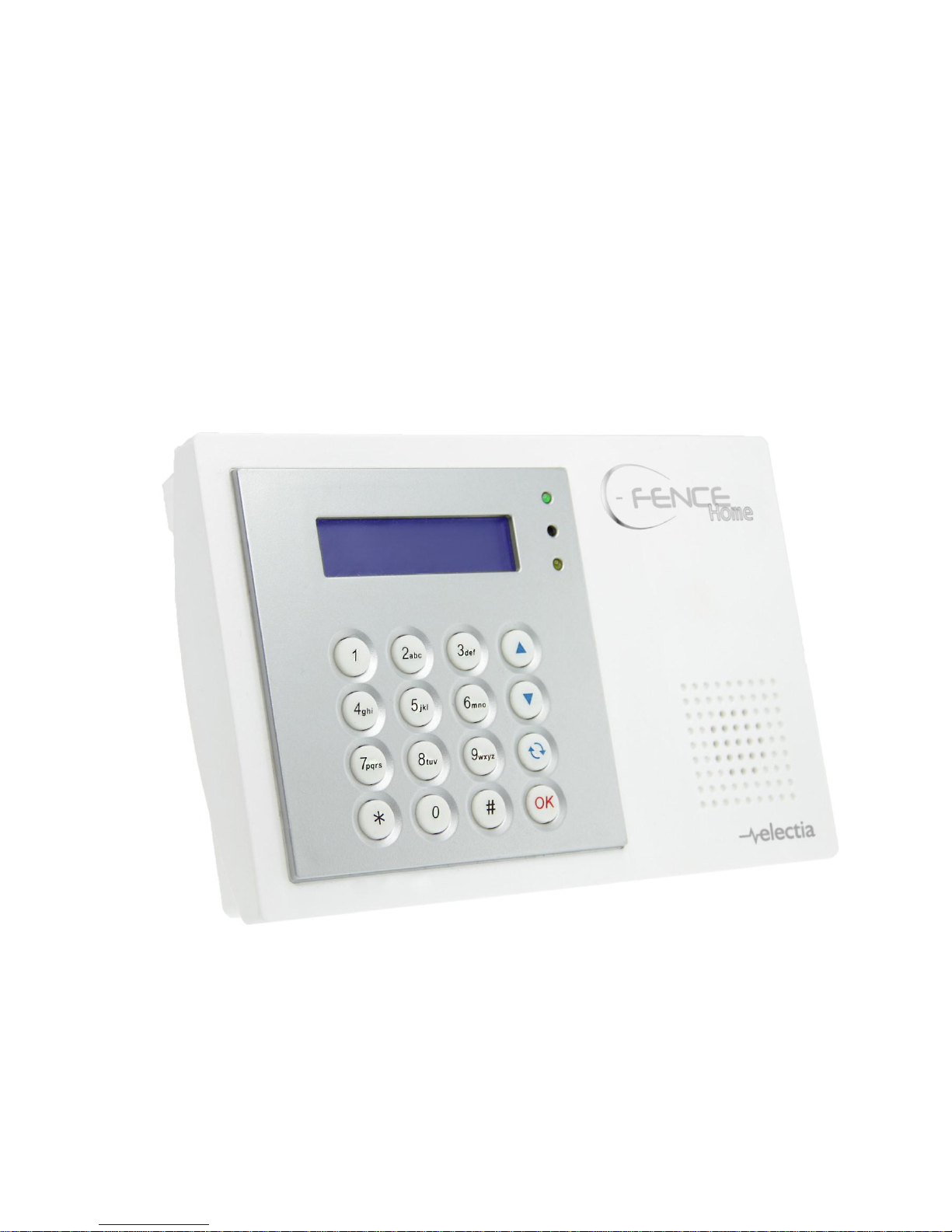
1.1. Identifying the parts
1. Backlit LCD Display
2. Green LED (Power Indicator)
Green LED ON – AC Power is supplied.
3. Yellow LED (Fault Indicator)
FAULT LED ON – Indicate that there is
fault situation in the current Operating
Area (Home/Alarm off modes only, LED
dims in Arm mode even if fault is
detected).
FAULT LED OFF – Indicate that there all
fault conditions are restored.
4. Numeric Keys
5. Key
— In Programming mode, press this key
to move the cursor and scroll the
display upwards.
6. Key
— In Programming mode, press this key
to move the cursor and scroll the
display downwards.
7. Key
In Programming mode, use this key for
deleting a digit, canceling the selection,
aborting the current screen and returning
to the previous screen etc.
8. OK Key
To confirm the keyed-in data or confirm
the selection.
9. # Key
— Press & hold for 2 sec to enter the
Programming menu.
10. key
11. Buzzer
12. Power Supply Compartment Cover
13. GPRS/GSM LED Indicator
14. GPRS/GSM SIM Card Base
This slot is for inserting SIM card.
15. Factory Use Only
16. Factory Use Only
17. Factory Use
18. Battery Switch
19. DC Jack
20. Wall Mounting Holes with Tamper
Switch Inside
21. Wall Mounting Bracket

2
1.2. Insert GSM/GPRS SIM
Card
C-FENCCE HOME Panel features built-in
GSM/GPRS communication facility to report to
the Monitoring Station.
To Insert your GSM/GPRS SIM card:
<<NNOOTTEE>>
It is recommended to disable the SIM
card PIN code before inserting into the
Control Panel.
<< IIMMPPOORRTTAANNTT NNOOTTEE>>
Please make sure the inserted SIM card
has GPRS and MMS funcitons. Otherwise, the
Control Panel can’t work properly.
The GSM SIM Card Base is situated
inside the Power Supply compartment:
Unlock the SIM card base by sliding the
cover toward OPEN direction.
Spring open the SIM card slot and insert
your new SIM card.
Replace the SIM slot onto the base lightly.
Remember to lock the SIM card base by
sliding the cover toward LOCK direction.
1.3. The Power Supply
An AC power adaptor is required to connect to
a wall outlet. Be sure only to use an adaptor
with the appropriate AC voltage rating to
prevent component damage.
A DC 12V output and 1A switching power is
generally used to power the Control Panel.
For all other battery status, please
refer to section 3.13.
1.4. How to Install the Control
Panel
The easiest way to get to know the system
and get it up and running quickly is to get
all the devices and accessories
programmed on a tabletop before locating
and mounting them.
The Control Panel can be mounted on the wall
or wherever desired. Ensure the Control Panel
is fitted at approximately chest height where
the display can be easily seen and the keypad
convenient to operate.
Using the 2 holes of the Wall Mounting
Bracket as a template, mark off the holes’
positions.
Drill 2 holes and fix the screws & plugs
provided.
Hook the C-FENCCE HOME unit onto the
Wall Mounting Bracket (holding the unit
with the front facing you).
1.5.Two – Level Passwords
In order to provide highest security when
operating the system, C-FENCCE HOME
offers 4 levels of authorization.
User PIN Code
PIN Code is the 1st level of
passwords.
The Control Panel consists of 6 user
PIN codes. Same User PIN code may
not be repeated.
<< IIMMPPOORRTTAANNTT NNOOTTEE>>
No 2 codes can be the same, if so, the
message, Code in use will be
displayed to prompt the user to
choose differently.
User 1 PIN code can be changed, but
cannot be deleted in any way.
Whenever panel asks to key in Enter
Code or P-Code, please enter your User
PIN Code.
User Pin Code:
Factory default: 1234
User 2~6 PIN codes are deactivated by
factory default.

3
Master Code
The Master Code has the authorization to
enter Programming Mode. When the
display panel asks you to key in M-Code,
please enter your Master Code.
Master Code:
Factory default: 1111
1.6. Getting Started
<<IIMMPPOORRTTAANNTT NNOOTTEE>>
The Control Panel has Screen Saver
feature. The Alarm on / off message
will be displayed for 180 secs. Then,
only the current date & time will be
displayed.
While entering PIN code, if incorrect
codes have been inputed for 4 times
or over 20 incorrect numeric numbers
have been entered, it will inhibit
further key presses for 1 minute.
Press key will clear the code field,
or return to the previous screen.
After any changes are made in
settings, you must return to Alarm off
mode in order to save the changes. If
not returned to Alarm off mode or if AC
power & battery are both off, then the
changes will not be saved.
Step 1. Find a suitable location for the Control
Panel to be installed.
Step 2. Apply the AC Power. You will hear
one long beep. Alarm On will be
displayed on the first line and 00:01
01 Jan displayed on the second line
of the screen indicating the system is
in Away mode (factory default).
Step 3. Key-in your 4 digits User 1 PIN Code
within 30 sec.
Step 4. Press OK. You will hear 2 short beeps
and the display will show.
A l a r m O f f
0 0 : 0 1 J a n 0 1
The system is now in Alarm off mode.
<<NNOOTTEE>>
Whenever the Control Panel is
powered on again, it will resume the
mode before the power is
off/disconnected.
OK key confirming the entered PIN
code should be pressed within 30 sec.
Otherwise, the display will go back to
Alarm On and the system remains
armed, the display will go back to the
previous mode.
In Step3, if you press a key other than
numeric keys, the display will remain
the same requesting you to key in
1234 (default PIN code) and then
press OK.

4
2.Configuring Your
System
<<IIMMPPOORRTTAANNTT NNOOTTEE>>
While entering any PIN codes, if
incorrect codes have been input for 4
times; or over 20 numeric numbers
have been entered, it will inhibit
further key presses for 1 minute.
I. Entering Programming mode
If the system is in Alarm off mode, to enter the
Programming mode, follow the steps below.
Step 1. Press and hold # key for 2 seconds.
The screen will prompt you to enter
the User1 PIN code.
P - M o d e E n t e r
P - C o d e . . . .
Step 2. Key-in your 4 digits User PIN Code
within 30 sec.
Deafult user 1 PIN code:
Factory Default: 1234
The screen will then prompt you to
enter the Master PIN code.
P - M o d e E n t e r
M - C o d e . . . .
Step 3. Key-in 1111 (default Master Code)
within 30 sec.
Step 4. Press OK
The following message is displayed
for 2 sec.
W e l c o m e t o P r o g r a m m e n u
Step 5. Then the available selections pf the
Programming Main menu will be
displayed.
o G e n . S e t t i n g s
S p c . S e t t i n g s R e p o r t i n g
G S M
Step 6. Move the cursor to the desired item,
and press OK to confirm the selection.
The display will show you the
individual programming screen
accordingly.
<<NNOOTTEE>>
If a down-arrow symbol V appears on
the last column of the screen, it
indicates the selection list can be
downwards scrolled. If the lowest
position is reached, the down-arrow
symbol disappears.
If an up-arrow symbol Λ appears on
the last column of the screen, it
indicates the selection list can be
upwards scrolled. If the upper
position is reached, the up-arrow
symbol disappears.
In Programming mode, if no key is
pressed within 2 minutes, the Control
Panel will automatically exit
Programming mode to Alarm off mode.
2.1. Gen Settings (General
Settings)
o W a l k T e s t
C o d e S e t t i n g s
M a s t e r C o d e
G e n S e t t i n g s
S M S H e a d e r S M S k e y w o r d
D e v i c e s + / -
2.1.1 Code Settings
In Code Settings menu, the following
parameters can be programmed at your
discretion.
o P i n C o d e
D u r e s s C o d e T e m p . c o d e
<<IIMMPPOORRTTAANNTT NNOOTTEE>>
For Naming the User Name, pleas
refer to section Appendix, Naming
section for more information.
if the code is not correct, a Code

5
incorrect prompt message will be
displayed 2 sec., and you are
requested to repeat Step 2 to enter
again.
The code cannot be duplicated. If the
code has been used, the screen will
display code in use and require you
re-enter a new code.
2.1.1.1 Pin Code
All User Pin Codes are used to regularly
arm/disarm the system and are allowed to
access the Programming mode
accompanied with the Master Code.
User PIN code #2~#6 are deactivated by
factory default.
User Pin Code:
Factory default: 1234
To set PIN code
Step 1. Move the cursor to the Pin Code then
press OK selection.
* 1 )
2 ) . . . .
to
6 ) . . . .
Step 2. Move the cursor to the desired User
Pin Code then press OK.
E n t e r N e w C o d e
. . . .
Step 3. You are then required to enter your
preferred 4-digit code and then press
OK.
Step 4. Repeat the new code again and then
press OK.
R e p e a t N e w C o d e
. . . .
Step 5. A latch report on/off option is required
to choose:
o L a t c h r p t O n
L a t c h r p t O f f
v
<<NNOOTTEE>>
The Latch rpt On/Off section display
for your programming only when the
Latch selection function is enabled
(See section 2.2.2 under Configuring
your system)
The latch reporting function can be set
respectively for each Pin code.
Latch Report ON = Whenever the
system is armed, home armed or
disarmed, the Panel will transmit SMS
Contact ID code / SMS message /
GPRS reporting (according to presetting) to notify the Central
Monitoring Station.
Latch Reprot OFF = Whenever the
system is armed, home armed or
disarmed, the Panel will NOT transmitt
reporting(s) to notify the Central
Monitoring Station.
Step 6. Choose whether you wish to enable or
disable the latch report option and
press OK.
Step 7. You are then requested to give a name
for this new PIN code.
U s e r N a m e _
<<NNOOTTEE>>
A max of 10 digits for user name.
Step 8. Press OK to confirm the new name. If
no name is wished, press OK directly.
* 1 ) M R . S M I T H
2 ) M R S . S M I T H 3
)
4 ) . . . .
<<NNOOTTEE>>
2) MRS. SMITH representing the User
#2 PIN code is set up and user name
specified.
3) representing this User #3
code is programmed without user
name specified.
4) ●●●● representing the User #4
code is not yet set up for activation.
Step 9. Proceed to set additional User PIN
Codes as instructed from Step 1 ~
Step 8. Setting the PIN code is
completed.
6
<<IIMMPPOORRTTAANNTT NNOOTTEE>>
For Naming the User Name, please
refer to section 5. Appendix, Naming
section for more information.
if the code is not correct, a Code
incorrect prompt message will be
displayed 2 sec., and you are
requested to repeat Step 2 to enter
again.
The code cannot be duplicated. If the
code has been used, the screen will
display code in use and require you
re-enter a new code.
To Edit Pin Code
After the Pin Code is programmed, it can be
edited by following the steps below:
Step 1. Move the cursor to the Pin Code
selection then press OK.
D e l e t e p i n - c o d e
( O K ? )
Step 2. Press key, the next screen will ask
you to enter your new PIN code and
repeat it for double confirmation.
Step 3. Make your selection whether to have
the Latch Key Reporting ON or OFF,
and then press OK. The screen
returns to Code Setting menu, editing
the user PIN code is now completed.
To Delete User PIN code
Except User #1 which is activated by factory
default and can’t be deleted in any way,
User(#2~6) PIN code can be deleted by
following the steps below:
Step 1. Move the cursor to the PIN Code
selection then press OK the following
screen will show the status of each
User PIN code:
* 1 ) M R . S M I T H
2 ) M R S . S M I T H
3
)
4 ) . . . . . .
Step 2. Move the cursor to the desired # (2~6)
of programmed user PIN code to be
deleted, then press OK the following
screen is displayed.
D e l e t e p i n - c o d e
( O K ? )
Step 3. Press OK and the screen returns to
previous one with the deleted User
PIN code marked with ●●●●
2.1.1.2 Duress Code
The Duress Code is designed for
transmitting a secret & silence alarm.
When Duress Code is used for accessing
the system, the Control Panel will report a
secret alarm message without sounding
the siren to the Central Monitoring Station
to indicate of a Duress Situation in
Progress. The LCD will display in the
same manner as if operating with a User
PIN Code. There will be no Alarm! Alarm!
warning message, nor any siren sound.
The Duress Code consists of 4 digits and
is not activated as default by the factory.
To set/change the Duress Code, follow
the same steps as those to set
/change/delete the user PIN code
described in previous section.
2.1.1.3. Temporary Code
The temporary Code is also used to
arm/disarm the system for a temporary
user. It is ONLY valid for one-access per
arming and disarming. Afterwards, the
Temporary Code will be automatically
erased and needs to be reset for a new
Temporary user.
The Temp. Code consists of 4 digits and is
not activated as default by the factory.
Latch Selection must set as Optional
Latch (please refer to section 2.4.4 for
details), so that a Latch Report On/Off
selection will appear.
To set/change the temporary Code,
follow the same steps as those to set
/change/delete the user PIN code
described in previous section.
2.1.2 Master code
Master Code is used for accessing the

7
Programming mode.
Factory default: 1111
To set/change the Master Code, follow
the same steps as those to set
/change/delete the user PIN code
described in previous section.
2.1.3 Panel Setting
A . E n t r y t i m e r
A . E x i t t i m e r
H . E n t r y t i m e r
H . E x i t t i m e r A . E n t r y s o u n d
A . E x i t s o u n d
H . E n t r y s o u n d
H . E x i t s o u n d
D o o r c h i m e W a r n i n g b e e p M o b i l i t y L o c a l s i r e n
I n t e r f e r e n c e
T a m p e r a l a r m
A l a r m l e n g t h
S i r e n d e l a y F i n a l d o o r
V e r i f i c a t i o n
2.1.3.1 A. Entry Timer (Away Entry
Timer)
When Door Contact (DC) or PIR Detector (IR)
is set as Entry / Away Entry attribute, the
system gets into counting down period (Away
entry timer) while the DC or IR is triggered
under Away arm mode.
During the counting down period, it is allowed
to use correct PIN code to disarm the alarm
and the alarm reporting will not be sent. On the
other hand, if the correct PIN code has not
been entered within the period, Control Panel
raises an alarm and sends an alarm report.
Options available are disable (alarm
immediately) , 10 sec., 20 sec., up to 70
sec. in 10-sec increments.
Press OK on A. Entry Timer and the
following screen will be displayed:
D i s a b l e
1 0 s e c o 2 0 s e c
3 0 s e c
4 0 s e c
5 0 s e c
6 0 s e c
7 0 s e c
20 sec. is set as factory default.
2.1.3.2 A. Exit Timer (Away Exit Timer)
While the system gets into Away arm mode by
Control Panel, Remote Controller (RC) or
Remote Keypad (KP), an Away exit timer starts
counting down.
During the counting down period, pressing the
Arm Button of the RC can restart the counting.
In addition, it is allowed to use correct PIN
code or press Disarm Button of the RC to stop
the counting and return to Alarm off mode.
Options available are Disable (exit timer
prohibited), 10 sec., 20 sec. up to 70 sec.
in 10-sec increments.
30 sec. is set as factory default.
2.1.3.3 H. Entry Timer (Home Entry
Timer)
When Door Contact (DC) or PIR Detector (IR)
is set as Entry / Home Access attribute, the
system gets into counting down period (Home
entry timer) while the DC or IR is triggered
under Home arm mode.
During the counting down period, it is allowed
to use correct PIN code to disarm the alarm
and the alarm reporting will not be sent. On the
other hand, if the correct PIN code has not
been entered within the period, Control Panel
raises an alarm and sends an alarm report.
Options available are disable (alarm
immediately) , 10 sec., 20 sec., up to 70
sec. in 10-sec increments.
20 sec. is set as factory default.
2.1.3.4 H. Exit Timer (Home Exit Timer)
While the system gets into Home arm mode by
Control Panel, Remote Controller (RC) or
Remote Keypad (KP) or Night Switch(NS), an
Away exit timer starts counting down.
During the counting down period, pressing the
Home Button of the RC can restart the
counting. In addition, it is allowed to use

8
correct PIN code or press Disarm Button of the
RC to stop the counting and return to Alarm off
mode.
Options available are Disable (exit timer
prohibited), 10 sec., 20 sec. up to 70 sec.
in 10-sec increments.
30 sec. is set as factory default.
2.1.3.5 A. Entry Sound (Away Entry
Sound)
This is for you to decide whether the Control
Panel sounds count-down beeps and volume
of beep during the Away entry timer (see
section 2.3.3.1).
Options available are High (high volume of
beep), Low (low volume of beep) and Off
(no beep):
H i g h
o L o w
O f f
Low is set as factory default.
2.1.3.6 A. Exit Sound (Away Exit Sound)
This is for you to decide whether the Control
Panel sounds count-down beeps and volume
of beep during the Away exit timer (see section
2.3.3.2).
Options available are High (high volume of
beep), Low (low volume of beep) and Off
(no beep):
Low is set as factory default.
2.1.3.7 H. Entry Sound (Home Entry
Sound)
This is for you to decide whether the Control
Panel sounds count-down beeps and volume
of beep during the Home entry timer (see
section 2.3.3.3).
Options available are High (high volume of
beep), Low (low volume of beep) and Off
(no beep):
Low is set as factory default.
2.1.3.8 H. Exit Sound (Home Exit Sound)
This is for you to decide whether the Control
Panel sounds count-down beeps and volume
of beep during the Home exit timer (see
section 2.3.3.4).
Options available are High (high volume of
beep), Low (low volume of beep) and Off
(no beep):
Low is set as factory default.
2.1.3.9 Door Chime
This function is available only when the
attribute of Door Contact (DC) and/or PIR
detector (IR) is set as Entry or Away Entry.
The Control Panel sounds a Door Chime
(Ding-Dong Sound) while the DC and/or IR is
activated in Alarm off mode.
Options available are High (high volume of
sound), Low (low volume of sound) and
Off (no sound):
H i g h
o L o w
O f f
Low is set as factory default.
<<NNOOTTEE>>
IR Camera(CTC-852) doesn’t support the Door
Chime function.
2.1.3.10 Warning Beep
This is for you to decide whether the Control
Panel will sound a warning beep whenever a
fault condition has been detected and
displayed. The warning beep will be silenced
after the Fault message has been read by the
user. When a new fault condition is detected, it
will then again emit a warning beep every 30
sec.
Options available are High (high volume of
warning beep), Low (low volume of
warning beep) and Off (no beep):
H i g h
o L o w
O f f
Low is set as factory default.
9
2.1.3.11 Mobility
This function is design to avoid an accident
happening (e.g. swoon or lost consciousness)
to the user without anyone notices. Under all
modes except Away arm mode, when the
system does not detect any user movement
within the pre-set mobility period, an inactivity
(alarm) report will be sent to the monitoring
center. The display will show Alarm! Alarm! and
the siren will sound.
Options available are Disable (no mobility
detecting), 4 hours, 8 hours and 12
hours.
o D i s a b l e
4 H o u r s 8 H o u r s
1 2 H o u r s
Disable is set as factory default.
<<NNOOTTEE>>
The mobility time re-calcutelates once one
of the following actions occurrs:
In Home mode: whenever any key of
Control Panel is pressed, or whenever
any Home Omit DC or IR is triggered
within the pre-set Mobility time period.
In Alarm off mode: whenever any of
the DC or IR (except 24 Hr, Fire,
Medical Emergency and Water) is
triggered, or whenever any keys of the
Control Panel / RC / KP is pressed
within the pre-set Mobility time period.
The mobility function is disabled
automatically when the system is set to
Away Arm.
IR Camera (CTC-852) doesn’t support the
Mobility funciton.
2.1.3.12 Local Siren
This is used to program whether the Control
Panel raises local alarm while sensor is
triggered.
o O n
O f f
On (Local Siren On) is set as factory
default. When the Control Panel receives
an effectual triggered signal, its siren
raises alarm.
Off (Local Siren Off) means when the
Control Panel receives an effectual
triggered signal, its siren will not raise
alarm.
<<NNOOTTEE>>
Whe Local Siren is set is OFF, the Bell Box
(BX) and Indoor Siren (SR) are not
affected and will emit an alarm sound.
2.1.3.13 Interference
This is for you to decide whether the Control
Panel should detect signal jamming or not.
D e t e c t i o n O n
o D e t e c t i o n O f f
Detection Off is set as factory default.
<<NNOOTTEE>>
When the Detection On is selected,
whenever the signal jamming period
lasted longer than 30 seconds, this
fault event will be logged, reported to
the Central Monitoring Station and
displayed on the LCD to warn the user.
When the Dectection Off is selected,
Control Panel will not check
interference status.
2.1.3.14 Tamper Alarm
This is for you to choose whether the siren
should sound alarm when the tamper is
triggered.
O A w a y A r m O n l y N o r m a l
V
Away Arm Only is set as factory default.
Away Arm Only means, when tamper
is triggered under Away arm mode,
Control Panel raises a local alarm and
sends report to the monitoring center.
While under others modes (Home/
Alarm off modes, etc.), the siren does
not sound nor any report will be sent,
Normal means, Control Panel raises
a local alarm for tamper-trigger in all
mode.
Either Away arm only or normal is
10
selected, the system sends tampertriggered report to Central Monitoring
Station in all modes while tamper is
triggered.
<<NNOOTTEE>>
After the status of IR Camera
Tamper or Tilt Switch is restored,
IR camera won’t detect the status
of Tamper and Tilt Switch for 5
minutes. After 5 minutes, IR
camera will continue reporting
tamper status to the Control Panel.
2.3.3.15 Alarm Length
This is for you to select the built-in siren
duration when an alarm is activated. Options
are disable (no siren alarm) and 1-min to 15min in 1- min increments.
D i s a b l e
1 M i n
2 M i n
o 3 M i n
4 M i n 5 M i n
to
1 5 M i n
3 minutes is set as factory default.
If Disable is selected, when the Control
Panel receives alarm signal, the panel
siren, Bell Box (BX) will not raise an alarm
sounding.
If 1~15 min is selected and the local siren
function is disabled (see section 2.3.3.12
above), the panel siren will not raise an
alarm when alarm is triggered. However,
the BX will raise siren based on your
programming (see the operation manual of
BX).
If BX’s alarm length is longer than the
Control Panel’s, the system gives priority
to the Control Panel. (e.g. when the BX’s
alarm length is set as 3 mins, and the
panel’s alarm length is set as 1 min, both
alarm siren stop at 1 min when alarm is
triggered; however, the BX’s LED keeps
flashing until 3 mins is expired.
2.3.3.16 Siren Delay
This is for you to decide how long should the
Control Panel suppress the audible alarms
after a Burglar or Entry alarm is reported.
Options are disable and 1-min delay to 10-min
delay in increments of 1 minute
o D i s a b l e
1 M i n
.
.
.
1 0 M i n
Disable is set as factory default.
<<NNOOTTEE>>
Some audible alarm will not be
delayed (disregard its siren delay
setting) when the following cindition
detected:
Fire alarm
Water alarm
Personal panic alarm
Medical emergency
Tamper alarm
GSM/GPRS failure
The alarm reporting will be sent
immedicately, even if the audible
alarm is delayed.
2.3.3.17 Final Door
When the system is under away arming (see
section 4.2.1) with Final Door set to On and a
Door Contact set as Entry device, then, the
system will automatically full arm the system
once this Door Contact is detected as closed,
event if the count-down period is not yet
complete.
o F i n a l d o o r O n
F i n a l d o o r O f f
v
Final Door On (Final Door Set Option On)
is set as factory default.
2.3.3.18 Verification
This is use to set the Sequential Verification
Reporting.
11
o O n
O f f
Off (Verification Off) is set as factory
default.
<<NNOOTTEE>>
If there are more than one PIR motion
sensor or door contact, whose
attribute is set as Burglar, with
Verification On, when the first sensor
is triggered, the panel will report a
Burglar alarm (event code 130) to the
central monitoring station.
If a second sensor is triggered again
within 30 minutes, the panel will report
another Alarm confirm (event code
139) to the central monitoring station.
If Verification Off is selected instead,
the panel will only send the first
Burglar alarm (event code 130) to the
central monitoring station.
2.1.4 SMS Header
This feature allows you to set a SMS header
with every SMS alarm message reported to
your mobile phone for easy recognition.
E d i t S c r e e n
A maximum of 64 characters is allowed.
<<IIMMPPOORRTTAANNTT NNOOTTEE>>
For Key-in the SMS header & SMS
keyword, the keypad can be used to
enter text, similar to the texting
method being utilized for the mobile
phones
The keys have the following functions:
1
1 , ! ? - 【 】 @ /
2
2 A B C a b c
3
3 D E F d e f
4
4 G H I g h i
5
5 J K L j k l
6
6 M N O m n o
7
7 P Q R S p q r s
8
8 T U V t u v
9
9 W X Y Z w x y z
0
0 <space> / - & ’ . “+:
Delete character and backspace
Set SMS Header
Key-in your desired SMS header for a
maximum of 64 characters.
When the message is completed, press OK
and then to choose Save to save the newly
edited SMS header.
<<NNOOTTEE>>
When Save is chosen, the saved SMS
header will be sent along with the
SMS status message to mobile phone.
If no SMS header is programmed,
only the SMS alarm message will be
send to mobile phone.
To change/delete the SMS Header,
please follow the same step described
above.
2.1.5 SMS Keyword
For sending remote commands to system via
SMS message, a personalized password is
required for C-FENCCE HOME to recognize
your authority.
E d i t s c r e e n
_
Set SMS keyword
Key-in your desired SMS keyword for
maximum of 10 characters. Press OK to
confirm.
<<NNOOTTEE>>
If no SMS keyword is saved, the
remote commanding feature will NOT
be available.
To change/delete the SMS keyword,
please follow the same step described
above.
Once an SMS keyword is set, you
may use SMS text messages to
change the Control Panel’s mode.
2.1.6 Devices +/-
Devices +/- menu allows you to
 Loading...