

868MHz
Home Prosafe 1132 GSM
CTC 1132
GB User manual
SE Användarmanual
FI Manuaali
Art 36.2868

Table of Contents
Application Overview…………………………………………1
I. Identifying the parts……………………………..…………………………..……………………………………1
II. Insert GSM SIM Card………………………………..…………………………………………………………..2
III. The power supply……………………………………..………………………………………………………...2
IV. How to install the Control Panel……………………………………………………………………………….2
V. 2-level passwords……………………………………..…………………………………………………..3
VI. Getting Started……………………………………………..……………..………………………………….…3
Configuring Your System……………………………………………4
I. Entering programming mode………………………..………………………………………………………….4
II. Telephone Settings…………………………..…………………….……………………………………………5
III. General Settings………………………………..……………………..………………………………………8
IV. Special Settings……………………………………………………………………………………………13
V. ADD/Delete Device.…………………………..……………………………………………………………….16
VI. SMS Editor………….. ……………………..……………………………………………………………..…23
VII. SMS Keyword..……………. ……………………..………………………………………………………...24
VIII. Country Code………….. ……………………..…………………………………………………………..…24
IX. GSM Signal..……………. ……………………..………………………………………………………...25
X. Walk Test…………………………………………………………………………………………………25
XI. Reset GSM……………………………………………………………………………………………………..25
Operation……………………………………………………………26
I. Entering User Menu…………………………..…………………………………………………………….…..26
II. Away (Alarm On) Mode….………………………..………………………………………………………….26
III. Forced Arming ……..……. ……………………..…………………………………………………………..27
IV. Disarm (Alarm off) Mode……………………………..………………………………………………………28
V. Home Arm Mode…..……….……………………………..……………………………..……………………38
VI. Partial (By-pass) Arm mode…………………………………..……………………………………………..29
VII. Alarm Activation…………………………………..…………………………………………………………..30
VIII. Stop the Alarm and Alarm Display……. ……………………..……………………………………………31
IX. Event Log….……………………………..………………………………………………………………..32
X.Power Switch “Home Matic”………………………………………………………………………………….32
XI. False Alarm Management…………………………..………………………………………………………33
XII. Remote Commanding………………………..……………………………..………………………..…33
XIII. Dialling & Call Acknowledgment………………………..…………………………..……………………38
Appendix………………………………………………………40
I. Reset Procedure…………….………………..……………..……………………………………………….….40
CTC-1132 868AM 2007.07.18
1
3
Application Overview
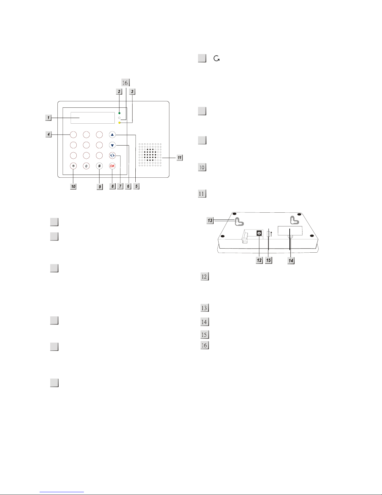
I. Identifying the parts
Backlit LCD Display
Green Power LED
— ON: AC Power is On.
— OFF: AC Power failure.
Yellow Fault LED
— On: when any fault situation Fault is
detected.
— Off: when all fault conditions are
restored. (The Unit is in Normal
Mode)
Numeric Keys
S Key
— Programming mode: press this key
to move the cursor and scroll the
display upwards.
T Key
— Programming mode: press this key to
move the cursor and scroll the
display downwards.
Key
— Programming mode: use this key to
delete a digit, cancel the selection,
abort the current screen, return to the
previous screen, etc.
OK Key
— To confirm the keyed-in data or
confirm the selection.
# Key
— Enter Programming menu
¿ Key
— Enter Installer menu.
Buzzer
DC jack
— DC 9V 500mA power adapter
connection.
2 Mounting Holes & Tamper.
SIM card holder cover
Battery Switch.
Microphone.
1
2
7
8
5
9
6
4
ON
1
23
45
6
78
9
abc
def
ghi jkl mno
pqrs
tuv wxyz
CTC-1132 868AM 2007.07.18
2
II. Insert GSM SIM Card
CTC-1132 Control Panel features built-in GSM
communication facility to make message
reporting to the phone numbers preprogrammed within the system.
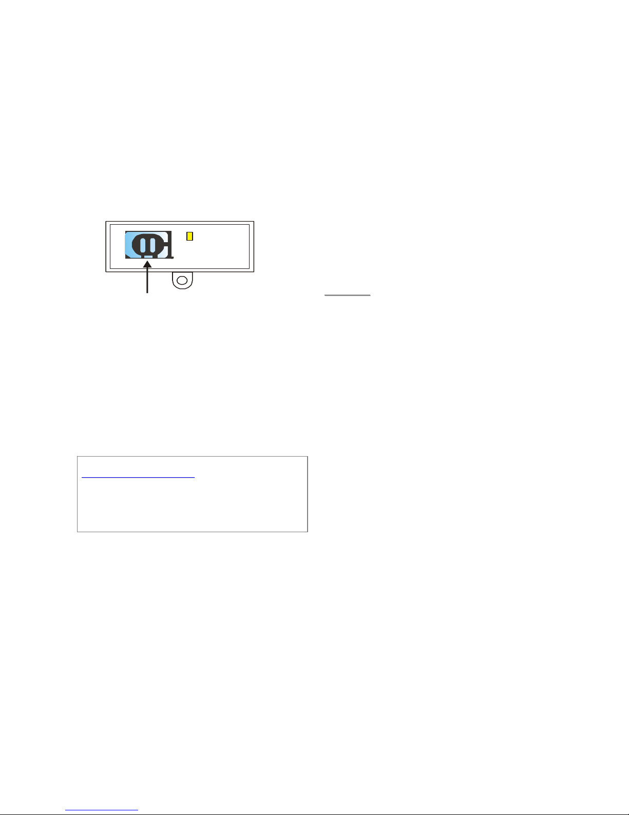
z To Insert your SIM card:
The GSM component is situated inside the
Power Supply compartment as pointed out
by the arrow below:
SIM CARD
z Unlock the SIM card base by sliding the
cover toward “OPEN-backward” direction.
z Spring open the SIM card slot and insert
your new SIM card.
z Replace the SIM slot onto the base lightly.
z Remember to lock the SIM card base by
sliding the cover toward “LOCK-forward”
direction.
<<IIMMPPOORRTTAANNTT NNOOTTEE>>
Be aware to only insert or remove SIM card
when the Control Panel is completely
depleted of any power residual.
III. The Power Supply
An AC power adapter is required to connect to
a wall outlet. Be sure only to use an adapter
with the appropriate AC voltage rating to
prevent component damage. A DC 9V output
and 500mA adapter is generally used to power
the Control Panel.
z Rechargeable Battery
z
In addition to the adapter, there is a
rechargeable battery inside the Control
Panel, which serves as a back up in case
of a power failure.
z The battery used is a Ni-MH 600mAH
7.2V rechargeable battery.
z During normal operation, the AC power
adapter is used to supply power to the
Control Panel and at the same time
recharge the battery.
z When the battery is fully charged, it can
provide back-up power for a period of
about 8 hours. It takes approximately 48
hours to fully charge the battery.
<<NNOOTTEE>>
" If the AC power is missing and the
battery is near exhaustion, a low
battery message will be displayed and
the internal siren and Backlit feature
will be disabled to conserve power.
IV. How to install the Control
Panel
The easiest way to get to know the system
and get it up and running quickly is to get
all the devices and accessories
programmed on a tabletop before locating
and mounting them.
The Control Panel can be mounted on the wall
or wherever desired. Ensure the Control Panel
is fitted at approximately chest height where
the display can be easily seen and the keypad
convenient to operate.
z Using the 2 holes of the Wall Mounting
Cross Bracket as a template, mark off the
holes’ positions.
z Drill 2 holes and fix the screws & plugs
provided.
z Hook the CTC-1132 unit onto the Wall
Mounting Cross Bracket (holding the unit
with the front facing you).

CTC-1132 868AM 2007.07.18
3
V. 2 – level passwords
In order to provide highest security in operating
the system, CTC-1132 offers 2 levels of
authorization. That is
9 Personal PIN Code
9 Master Code
A. PIN Code
z There are a total of 4 User PIN Codes
per each system. The PIN Code is
the 1st level of password. It has the
authorization for daily operation, such
as
9 Arm the system
9 Disarm the system
9 Enter the Home mode
9 Partially arm the system (By-pass
mode)
9 Display Fault events
9 View the Event log
9 Power Switch (Home Matic)
z “1234” is set as default User #1 PIN
Code by the factory.
z User PIN code #2~#4 are deactivated
by factory default
B. Master Code
z The Master Code has the
authorization to enter Programming
mode. In Programming mode, the
following options can be programmed.
9 Add the device in
9 Edit the devices
9 Remove a device
9 Program the External Siren
9 Edit Power Switch “HomeMatic”
9 Set Pin Code
9 Set Temporary Code
9 Set Duress Code
9 Set Master Code
9 Set Telephone Numbers
9 Set Messages
9 Set SMS related Features
9 Select Walk Test mode
9 GSM signal
9 SMS Keyword
z “1111” is set as default Master Code
by the factory.
<<NNOOTTEE>>
) No any two codes can be the same, if
so, the message, “Code in use,
Select another” will be displayed to
prompt the user to choose differently .
VI. Getting Started
Step 1. Find a suitable location for the Control
Panel to be installed.
Step 2. Apply the AC Power. You will hear a
long beep. “Alarm On” will be
displayed on the first line and “00:01
01 Jan” displayed on the second line
of the screen indicating the system is
in Away mode (this is the default
mode)
Step 3. Press “ 1 “ key on the keypad, the
display will show.
E n t e r C o d e
¿. . .
Step 4. Key in the remaining “234” (default
User1PIN code, 1234) within 30 sec.
Step 5. Press “OK”. You will hear 2 short
beeps and the display will show.
A l a r m O f f
0 0 : 0 1 0 1 J a n
The system is now in Disarmed mode.
<<NNOOTTEE>>
) In Step 4, press “ “ (cancel) key will
clear one previously entered code.
) “OK” key confirming the entered PIN
code should be pressed within 30 sec.
Otherwise, the display will go back to
“Alarm On” and the system remains
armed.
) During entering PIN code, if more than
20 keys (including “OK” & “
“ key)
were pressed without a valid PIN code
CTC-1132 868AM 2007.07.18
4
strings, it will inhibit further key
presses for 1 minute.
) In Step3, if you press a key other than
numeric keys, the display will remain
the same requesting you to key in
“1234” (default PIN code) and then
press “OK”.
) The Control Panel has “Screen Save”
function. The “Alarm off” message
will be displayed for 160 sec. only.
Afterwards only current date & time is
displayed on the second row line.
Step 6. Please wait for 2 to 3 minutes for the
system to read it status. Then, if the
yellow LED turns on, it indicates that
there is a fault. Press “1234” to enter
the user menu within 30 sec.
Step 7. Press “OK” and the display will show.
F a u l t D s p
A w a y A r m
H o m e A r m
B y p a s s
L o g
P o w e r S w i t c h
Step 8. Choose “Fault Dsp” and press “OK”
The following possible Fault will
display:
Configuring your system
I. Entering Programming mode
If the system is in Disarmed (Alarm off) mode,
to enter the Programming mode, follow the
steps below.
Step 1. Press “#” key.
The screen will prompt you to enter
the User1 PIN code.
P - M o d e E n t e r
P - C o d e . . . .
Step 2. Key in “1234” (default “User1” PIN
code) within 30 sec. Then, press “OK”
The screen will prompt you to enter
the Master PIN code.
P - M o d e E n t e r
M - C o d e . . . .
<<NNOOTTEE>>
) During keying in the PIN code, press
“
“ will clear one previously entered
code. If the code field is empty, press
“
“, the screen will exit and return to
“Alarm Off” screen.
Step 3. Key in “1111” (default “Master” Code)
within 30 sec.
Step 4. Press “OK”
The following message is displayed
for 2 sec.
P r o g r a m M e n u
M a k e a S e l e c t i o n
Step 5. Then the Programming Main menu will
be displayed.
O
W
a l k T e s t
Tel.S e t t i n g v
<<NNOOTTEE>>
) The cursor is indicated by a flashing dot
on the left upper corner. It can be
move up & down by pressing “S” &
“T” key respectively.
Step 6. Press “S” “T” keys to move the cursor
downward or upward. The screen is
also scrolled down or up respectively.
The following items can be selected.
9 Walk Test
9 Tel. Setting
9 Gen. Settings.
9 Spc. Settings
9 Devices +/-
9 SMS Editor
9 SMS Keyword
9 Country Code
9 GSM Signal
9 Reset GSM
Step 7. After making a selection by moving the
cursor to the desired item, press “OK”
to confirm the selection. The display
will show you the individual
programming screen accordingly.
<<NNOOTTEE>>
) If a down-arrow symbol “V” appears on
CTC-1132 868AM 2007.07.18
5
the last column of the screen, it
indicates the selection list can be
downwards scrolled. If the lowest
position is reached, the down-arrow
symbol disappears.
) If an up-arrow symbol “Λ” appears on
the last column of the screen, it
indicates the selection list can be
upwards scrolled. If the upper
position is reached, the up-arrow
symbol disappears.
) Pressing “ “, the screen will also
return to “Alarm Off” screen.
) After User1, 2, 3 & 4 PIN codes and
Master code are programmed with
new numbers, remember to enter the
newly programmed codes when
accessing Programming mode
afterwards.
) In Programming mode, if no key is
pressed within 5 minutes, the Control
Panel will automatically exit
Programming mode to Alarm Off
mode.
II. Telephone Settings
In “Telephone Settings” menu, the following
parameters can be programmed at your
discretion.
*
T e l . N u m b e r s
R e c o r d M s g
T e s t R e p o r t
1. Telephone Numbers
z In “Tel.Setting” menu, select “Tel Numbers”,
the screen allows you to set/change/delete
the emergency telephone numbers.
z A maximum of six numbers can be stored
in priority order (in the order of A. B. … to
F).
<<NNOOTTEE>>
) A, B,… to F represent the priority
number of the six tel. numbers
respectively.
) If the tel. number for a particular priority
number has not been stored, three
dots are displayed indicating the
memory spot is empty.
) Only 11 digits can be displayed on the
tel. Numbers list. Non fitting numbers
are indicated with after the incomplete
number.
z Store Tel. Numbers
Step 1. Move the curser to the “Tel. Number”
submenu and press “OK”.
The display will show the following
screen when no tel. number has been
entered:
* A)...
B)...
C)...
D)...
E)...
F)...
Step 2. Choose from “A” to “F” sets to store
your phone number. Then press “OK”.
<<NNOOTTEE>>
) The phone number “A” must be
entered, or the Panel will not dial
out at the Alarm situation.
The following screen will be shown for
you to enter the phone number.
E n t e r n e w N o . + O K
....... . . . . . . ...
Step 3. Key in your phone number.
Step 4. Press “OK”
The screen will then prompt you to
choose:
* V o i c e R e p o r t
S M S r e p o r t
<<NNOOTTEE>>
Voice Reporting: For an alarm event,
the reporitng is done via playing voice
messages. Available ones are: Burglar,
Medical Emergency, Fire and Panic to
the phone numbers programmed at
this step.
SMS Reporting: For an alarm event,
the reporting is done via sending preedited SMS messages to the mobile
phone numbers programmed at this
step.
Step 5. Select a preferred reporting style and
press “OK”, The screen will return to
CTC-1132 868AM 2007.07.18
6
the “Tel. Number” screen to show you
the stored phone number with a letter
V indicting it’s a Voice report style and
a letter S for SMS report style.
* A ) 2 2 1 8 0 5 5 1 V
B ) 2 6 9 4 0 6 3 3 S
<<NNOOTTEE>>
) The maximum length of a number is 20
digits including “¿” & “#”. If this length
is reached, the Control Panel will
sound 5 beeps and no key can be
keyed in except “ “ key and “OK”
key.
) During entering the number, the “ “ key
is used as backspace. However, if the
number field is empty, pressing the
“ “ key, the screen will return to
“Tel. Numbers” screen.
) During entering the number, when the
15th position is reached, non-fitting
numbers will scroll sideward to the left.
z Change Tel. Numbers
Step 1. On the “Tel. Number” screen. Press
“OK”.
Step 2. The following screen will be displayed
for you to confirm if you really want to
change.
C h a n g e N u mb e r
2 2 1 8 0 5 5 1 ? ( O k )
Step 3. Press “OK” to confirm. The following
screen will be displayed for you to
enter the new number.
E n t e r n e w N o . + O k
. . . . . . . . . . . . . . . .
<<NNOOTTEE>>
) Press “ “ to abort and the screen
returns to “Tel. Number” screen.
Step 4. Key in the new number and choose a
preferred reporting method.
Step 5. Press “OK”
The new number will then override the
previous one. The screen returns to
“Tel. Number” screen.
z Delete Tel. Numbers
To delete a telephone number, follow the Step
1 to Step 3 of “Changing Tel. Number”
described above, and when “Enter new No.”
prompt screen is displayed.
E n t e r n e w N o . + O k
....... . . . . . . ...
Step 4. Press “OK”, then the previous stored
number will be deleted.
2. Message Menu
z This menu is for you to record and play the
emergency messages.
R e c o r d M s g
T e s t r e p o r t
z With a total capacity of 20 sec, you are
allowed to record the emergency
messages in 5 parts.
Address message – 8 sec.
Burglar message – 3 sec.
Fire message - 3 sec.
Panic message - 3 sec.
Emergency message - 3 sec.
<<IIMMPPOORRTTAANNTT NNOOTTEE>>
) The “Address message” must be
recorded, or the Panel will not dial
out at the Alarm situation.
z In an emergency, the Control Panel will
dial the emergency phone numbers
according to the priority order, then first
play the Address message and then play
the specific part message (Burglar, Fire,
Panic and Emergency) according to the
nature of the alarm raised.
z Recording the messages
When the “Record Msg.” is selected, the
following “Recording Selection” menu is
displayed for you to select which part of the
message is to be recorded.
R e c . A d d r e s s
R e c . S p e c i f I c
Stop
CTC-1132 868AM 2007.07.18
7
z Recording Address message
Step 1. Move the cursor to select “Rec.
Address” and then press “OK”, the
screen will ask you to confirm.
C h a n g e
A d d r e s s M s g + O k
Step 2. Press “ “ to abort. Or press “OK”
to confirm. A prompt Message will be
displayed for 2 sec.
S t a r t R e c o r d i n g
A f t e r t h e B e e p
Step 3. After 2 sec, the Control Panel will
sound a long beep, the following
prompt message will be displayed,
and recording can be started.
* N o w R e c o r d i n g *
E n d w i t h O k
Step 4. Press “OK” to end the message; the
screen will go to “Specific Part
Selection” menu to allow you to
select a specific part to be recorded.
<<NNOOTTEE>>
) To end recoridng at any time, press “
“ and the message will be saved as it is.
The screen returns to “Recording
Selection” menu.
) The maximum length of Address
message is 8 sec. When the 8 sec
duration is over, recording will be
stopped automatically. The message
being recorded will be saved.
) When recording, make sure you are
facing the microphone and are within 30
cm infront of it.
z Recording Specific Alarm messages
If “Rec. Specific” is chosen, the
specific alarm message selection
menu is displayed for you to select
the desired one.
B u r g l a r M s g
F i r e M s g
P A M sg
E m e r g e n . M s g
S t o p
Selection a specific message and
follow the same procedure as those
for recording Address message to
record each specific message
respectively.
<<NNOOTTEE>>
) The message length for each specific
message is 3 sec only.
z Changing a message
If for any reason, you want to change any part
of the recorded message, just follow the same
procedure to record a new message for that
part. The new message will override the
previous one.
z Test Report
Control unit allows you to test whether
telephone function is working properly or not
with the pre-set telephone numbers.
Step 1: Using “V” or ”Λ” cursors to select the
test-call number to test dial. Press
“OK” to confirm.
Step 2: Following screen will appear:
D i a l i n g . . . . . . . . .
. . . . . . . . . . . . . . . .
Step 3: Panel will show what messages are
being played. The word prompt will
shows the following:
“Now Playing:
Address Msg
Emergen. Msg
PA . Msg
Fire Msg.
Burglar Msg
The “Address Message” will be
played first. Followed by “Emergency
Message” and “Burglar Message”.
PA . Message The last “” will be
played to the recipient and to confirm
their reception & end the call by
pressing DTMF “#9”
<<NNOOTTEE>>
) Messages will be played in the following
order: Address, Emergency Panic ,Fire
& Burglar message.
) Until the recipient acknowledges and
confirms acknowledgement on his or her
phone, the control unit will play the

CTC-1132 868AM 2007.07.18
8
message for 85 sec. before returning to
selection menu.
) Pressing “ ” will return you to the menu
with the list of numbers.
) If the Burglar message, Emergency
Message, Panic message or Fire
message has not been recorded, when
you do the Test Report, it will be ignored.
z Changing a message
If for any reason, you want to change any part
of the recorded message, just follow the same
procedure to record a new message for that
part. The new message will override the
previous one.
III. General Settings
In “General Settings” menu, the following
parameters can be programmed at your
discretion.
*
P i n C o d e
T e m p . C o d e
D u r e s s C o d e
M a s t e r C o d e
A . E n t r y T i me
A . E x i t T i m e
H . E n t r y T i me
H . E x i t T i m e
D o o r C h i me
T i me
D a t e
P a n e l S i r e n
L a n g u a g e
1. Pin Code
z There are 4 User Pin Code in total, and
each consists of 4 digits. User PIN code
#1 is activated with “1234” as factory
default. Before you set your own User PIN
Code #1, “1234” has to be keyed in every
time “Entering Code” is required.
z User PIN code #2~#4 are deactivated by
factory default.
z All 4 User Pin Codes are used to
regularly arm/disarm the system and are
allowed to access the Programming mode
accompanied with the Master Code.
z To set your own PIN code
Step 1. Move the cursor to the item “Pin Code”
then press “OK” the following screen
is displayed.
*
1)
¿¿¿¿
2)... .
3)... .
4)... .
Step 2. Move the cursor to the desired # of
User Pin Code” then press “OK” the
following screen is displayed.
E n t e r N e w C o d e
. . . .
Step 3. You can key in your preferred 4-digit
number then press “OK”.
Step 4. The following screen will be displayed.
Repeat N e w C ode
. . . .
You are requested to enter the same
code again (as the one entered in Step
3)
Step 5. Key in the same code again, then
press “OK”. If the code is correct, the
following screen will ask you to enter
the user’s name for reference:
E n t e r N e w N a m e
....... . . . +Ok
Step 6. You are now invited to give a name for
this User who will be using this newly
programmed code to help better
understand system events. You can
enter up to 10 letters as you want for
the name followed by press “OK” or
just press “OK” for no name. Please
see section “User Naming” for details.
Then, the screen returns to the “PIN
Code” menu showing postprogrammed status of each User PIN
code:
*
1 ) M R . S M I T H
2 ) M R S . S M I T H
3)
¿¿¿¿¿¿
4)... .
<<NNOOTTEE>>
) 2) “MRS. SMITH” representing the
CTC-1132 868AM 2007.07.18
9
1 1
2 2ABCabc
3 3DEFdef
4 4GHIghi
5 5JKLjkl
6 6MNOmno
7 7PQRSpqrs
8 8TUVtuv
9 9WXYZwxyz
0 0<space>/-&’.”+
¿ ¿
# #
4
Delete character
and backspace
User #2 PIN code is set up and user
name specified.
) 3) “¿¿¿¿” representing this User #3
code is programmed without user
name specified.
) 4) “●●●●” representing the User #4
code is not yet set up for activation.
Step 8. Proceed to set additional User PIN
Codes as instructed from Step 2 ~
Step 7. When done, press “ ” and
the screen returns to “General
settings” menu, setting the PIN code
is completed.
<<NNOOTTEE>>
) In Step 5, if the code is not correct, a
“Code is not correct” prompt message
will be displayed 2 sec., and you are
requested to repeat Step 3 to enter
again.
User Naming
Each individual User can be given a name for
easy recogniztion when understanding system
events. User Names can be named in the firsttime setting or by resetting. The procedure is
similar for both situations.
z When the “Enter New Name” screen is
displayed, the keypad can be used to
enter text. Simply locate the
corresponding numeric keys to the desired
alphabets/symbols and press repeatedly
until the wanted alphabets/symbols appear.
Release the key and the flashing cursor
automatically jumps to the next position for
you to continue with the next letter by the
same method.
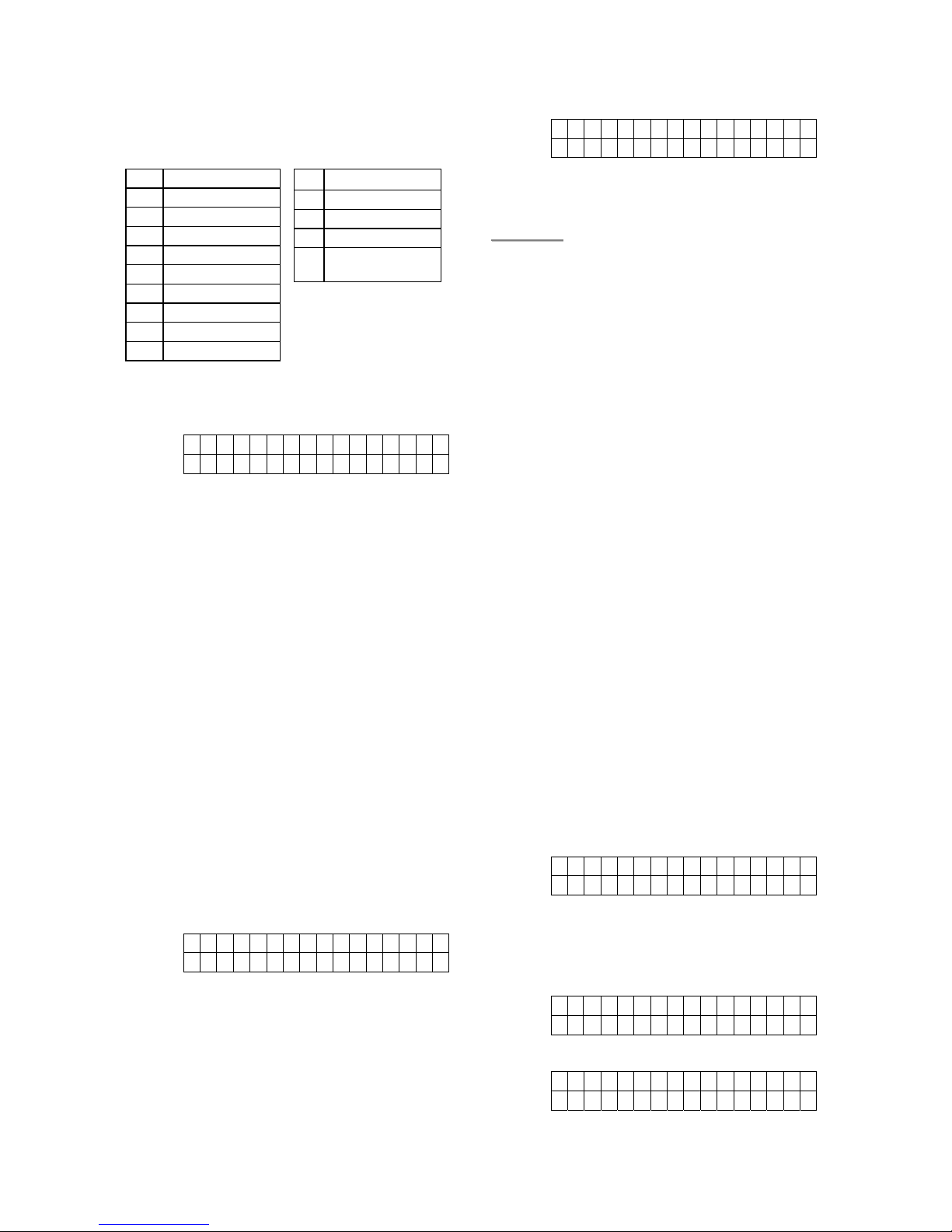
z The keys have the following functions:
z When the name is complete, press “OK”
to confirm and return to the previous or
main menu.
<<NNOOTTEE>>
) The name can be erased or clearing
the display by entering backward
spaces “
” and pressing “OK”.
z To Delete User PIN code
Except User #1 which is activated by factory
default and can’t be deleted in any way,
User#2, 3 and 4 PIN code can be deleted by
following the steps below:
Step 1. Move the cursor to the item “Pin Code”
then press “OK”, the following screen
will show the status of each User PIN
code:
*
1 ) M R . S M I T H
2 ) M R S . S M I T H
3)
¿¿¿¿¿¿
4)... . . .
Step 2. Move the cursor to the desired # (2~4)
of programmed user PIN code to be
deleted, then press “OK” the following
screen is displayed.
Delet e
P i n - C o d e ( + O k ) ?
Step 3. Press “OK” and the screen returns to
previous one with the deleted User
PIN code marked with “●●●●”.
z To Edit User PIN code
All 4 User PIN code can be edited freely by the
following steps:
Step 1. Move the cursor to the item “Pin Code”
then press “OK” the following screen
will show the status of each User PIN
code:
*
1 ) M R . S M I T H
2 ) M R S . S M I T H
3)
¿¿¿¿¿¿
4)... . . .
Step 2. Move the cursor to the desired # (2~4)
of programmed user PIN code to be
deactivated/deleted, then press “OK”
the following screen is displayed.
Delet e
P i n - C o d e ( + O k )
CTC-1132 868AM 2007.07.18
10
Step 3. Press “ “ key, the next screen will
ask you to enter your new PIN code
and repeat it for double confirmation.
Step 4. Follow the same steps as described in
“Set your own pin code” to edit.
2. Temporary Code
z The Temporary Code is used to
arm/disarm the system for a temporary
user and is valid only once per Arming and
once per Disarming. Afterwards, the
Temporary Code is automatically erased
and needs to be reset for a new Temporary
user .
z The Temp. Code consists of 4 digits and is
not activated as default by the factory.
z To Set Temporary Code
Step 1. Use the arrow keys to select “Temp.
Code” and press “OK”
E n t e r N e w C o d e
. . ..
Step 2. You can key in your preferred 4-digit
number and then press “OK”
R e p e a t N e w C o d e
. . ..
Step 3. You are prompted to re-enter the same
code again and press “OK”
If the code is correct, the screen
changes to the following:
*
L a t c h . R p t . O f f
L a t c h . R p t . O n
You are requested to choose to have
all arm/disarm actions of the user to be
reported to the Central Monitoring
Station or not.
Step 4. Press “S” “T” keys to select your
option and press “OK”. The screen
returns to “General Setting” menu,
setting the Temporary code is
completed.
<<NNOOTTEE>>
) There is no User Naming feature for
Temp. Code.
)
z To Delete Temp. Code
After the Temp. Code is programmed, it can be
deleted by following the steps below:
Step 1. Move the cursor to the item “Temp .
Code” then press “OK”.
Delet e
P i n - C o d e ( + O k )
Step 2. Press “OK” and the screen returns to
“Gen. Settings Menu”
z To Edit Temp. Code
After the Temp. Code is programmed, it can be
edited by following the steps below:
Step 1. Move the cursor to the item “Temp .
Code” then press “OK”.
Delet e
P i n - C o d e ( + O k )
Step 2. Press “ “ key, the next screen will
ask you to enter your new Temp. code
and repeat it for double confirmation.
Step 3. Press “OK”. The screen returns to
“General Setting” menu, editing the
Temporary code is now completed.
3. Duress Code
z Duress Code can arm/disarm the system.
When this code is used for accessing the
system, the Control Panel will report a
secret alarm message without sounding
the siren to the Call recipient to indicate of
a “Duress Situation in Progress”.
z The Duress Code consists of 4 digits and
is not activated as default by the factory.
z To Set Duress Code
Step 1. Use the arrow keys to select “Duress
Code” and press “OK”
E n t e r N e w C o d e
. . . .
Step 2. You can key in your preferred 4-digit
number and then press “OK”
Repeat N e w C ode
. . . .
Step 3. You are prompted to re-enter the same
code again and press “OK”
CTC-1132 868AM 2007.07.18
11
<<IIMMPPOORRTTAANNTT NNOOTTEE>>
When entering the following individual
setting screens, the value displayed on the
screen is the current setting of each item.
If it is not necessary to change the current
setting, just press “ “ to escape.
If the code is correct, the screen
returns to “General Setting” menu,
setting the Duress code is completed.
z To Delete Duress Code
After the DuressCode is programmed, it can be
deactivated/deleted by following the steps
below:
Step 1. To delete programmed Duress code,
select the “Duress Code” from the
“Gen. Setting Menu”, then, the
screen will show:
D e l e t e
P i n - C o d e ( + O k ) ?
Step 2. Press “OK” to confirm.
z To Edit Duress Code
After the DuressCode is programmed, it can be
edited by following the steps below:
Step 1. To edit programmed Duress code,
select the “Duress Code” from the
“Gen. Setting Menu”, then, the
screen will show:
D e l e t e
P i n - C o d e ( + O k ) ?
Step 2. Press “ “ key, the next screen will
ask you to enter your new Duress
code and repeat it for double
confirmation.
Step 3. Press “OK” and editing the Duress
code is completed.
4. Master Code
z Master Code is used for accessing the
Programming mode and it is set to “1111”
as factory default. Before you set your
own Master PIN code, “1111” has to be
keyed in every time it is required.
z To set your Master Code, follow the same
steps as in setting the “Duress Code”
described above.
z To Edit Master Code
After the Master Code is programmed, it can
be edited by following the same steps as in
editing the Duress Code described above.
<<NNOOTTEE>>
) The Master code can not be
deactivated (same as the User #1 PIN
Code).
) The Master Code is used only when
you enter the Programming mode.
In
other cases, only PIN Code should be
entered.
5. A. Entry Time
This is for you to select the Entry Delay time
when Away Arming. Options available are 0
sec., 10 sec., 20 sec., up to 70 sec. in 10-sec
increments.
A.Ent r y T i me
2 0 s e c . ( ΛVOK)
z Use “S”,“T” keys to switch between
options.
z Press “OK” to confirm.
z 20 sec. is set as factory default.
<<NNOOTTEE>>
) Full Arm Entry time applies only to the
zone that a Door Contact or PIR
Detector is installed and is set to
“Entry”.
) If incorrect PIN code is entered and/or
the entry delay time has expired, then
the system will trigger the Burglar
alarm.
6. A. Exit Time
This is for you to select the Exit Delay time
when Full Arming. Options available are 0 sec.,
10 sec., 20 sec. up to 70 sec. in 10-sec
increments.
A . E x i t T i m e
3 0 s e c . ( ΛVOK)

CTC-1132 868AM 2007.07.18
12
z Use “S”,”T” keys to switch between
options.
z Press “OK” to confirm.
z 30 sec. is set as factory default.
<<NNOOTTEE>>
) Full Arm Exit time applies only to the
zone that a Door Contact or PIR
Detector is installed and is set to
“Entry”.
) If incorrect PIN code is entered and/or
the Exit delay time has expired, then
the system will trigger the Burglar
alarm
7. H. Entry Time
This is for you to select the Entry Delay time
when Home Arming. Options available are 0
sec., 10 sec., 20 sec., up to 70 sec. in 10-sec
increments.
H . E n t r y T i m e
2 0 s e c . ( ΛV O K )
z Use “S”,“T” keys to switch between
options.
z Press “OK” to confirm.
z 20 sec. is set as factory default.
<<NNOOTTEE>>
) Home Arm Entry Delay time applies
only to the zone that a Door Contact
or PIR Detector is installed and is set
to “Entry”.
) If incorrect PIN code is entered and/or
the entry delay time has expired, then
the system will trigger the Burglar
alarm
8. H. Exit Time
This is for you to select the Exit Delay time
when Home Arming. Options available are 0
sec., 10 sec., 20 sec. up to 70 sec. in 10-sec
increments.
H . E x i t T i m e
3 0 s e c . ( ΛV O K )
z Use “S”,”T” keys to switch between
options.
z Press “OK” to confirm.
z 30 sec. is set as factory default.
<<NNOOTTEE>>
) Home Arm Exit Delay time applies only
to the zone that a Door Contact or PIR
Detector is installed and is set to
“Entry”.
) If incorrect PIN code is entered and/or
the Exit delay time is expired, then the
system will trigger the Burglar alarm.
9. Door Chime
This is for you to decide whether the Control
Panel will sound a Door Chime if the Door
Contact or PIR Detector is activated at the
Entry Point while the system is in Disarmed
mode.
Door C h i me On
Door C h i me Of f
z Press “S”,”T” keys to select the option
followed by “¿” appearing next to the
selected option.
z Press “OK” to confirm
z “Door Chime Off” is set as factory default.
<<NNOOTTEE>>
) When Door Chime is disabled, there
will be no door chime when Entry
point DC or PIR is triggered at
Disarmed mode.
) When Door Chime is enabled, the
system will make a “Ding-Dong”
sound to inform user that a DC or PIR
at Entry Point is triggered at Disarmed
mode.
10. Time
This is for you to program the current time to
be displayed. (hour & minute)
T i me S e t t i n g
00: 00 (
S
T
OK)
z Hour flashes first, use “S”,”T” keys to
choose a correct number for the current
hour. Hours are indicated by “00 ~ 23”.
z Press “OK” to confirm. Next, the screen

CTC-1132 868AM 2007.07.18
13
will be displayed for you to set the correct
minute.
z Minutes are then flashing.
z Use “S”,”T” keys to choose a correct
number.
z Press “OK” to confirm.
11. Date
This is for you to set the current date.
D a t e S e t t i n g
1 5 J a n (
S
T
OK)
z Months flash first, use “S”,”T” keys to
choose the current Month.
z Press “OK” to confirm. Next, the screen
will be displayed for you to set the current
day.
z Days are then flashing.
z Use “S”,”T” keys to choose the correct
day.
z Press “OK” to confirm.
12. Panel Siren
This is for you to decide to enable or disable
the Control Panel built-in Siren when there is
an alarm event.
S i r e n O n
S i r e n O f f
z Press “S” & “T” keys to select the option.
z Press “OK” to confirm
z “Siren On” is set as factory default
13. Language
This function is for setting the display language.
You can select English or Swedish. The screen
will show:
E n g l i s h
S w e d i s h
z Use “S”,”T” keys to choose the language.
z Press “OK” to confirm.
z Default: English
IV. Special Settings.
This menu is for the user to store the
specialized features for CTC-1132 system.
Step 1. Select Spc. Settings option..
Step 2. Press “OK”, then the Special Settings
Menu will be displayed.
A
larm L e n g t h
A
. E x i t S o u n d
A
.Ent r y S o u n d
H . E x i t S o u n d
H. Ent r y S o u n d
Sire n D e l a
y
Verif
i c a t i o n
Fi nal D o o r
Inter f e r e n c e
RC En t E
M o b i l i t y C H K .
Tampe r A l a r m
Super v i s i o n
Se t S I M - C o de
St o
p
<<NNOOTTEE>>
) Interference function is used in 868
Mhz frequency band Control Panel
only.
) Use “S” & “T” to move the cursor to
select the item, press “OK” to confirm
the selection.
) “¿” displayed in front of an option
indicates the current setting.
) In “Spc. Settings”, if no key is pressed
within 10 minutes, the Control Panel
will automatically exit this menu and
return to “Alarm Off” display.
1. Alarm length
This is for you to select the period of time that
the built-in siren will sound when an alarm is
activated. You can choose from 1 min. to 15
min. in 1-min increments.
A l a r m L e n g t h
3 mi n . ( ΛVOK)
z Use “ S “ & “ T “ keys to switch between
options.
z Press “OK” to confirm.
z 3 minutes is set as factory default.

CTC-1132 868AM 2007.07.18
14
2. A. Exit Sound
This is for you to decide whether the Control
Panel will sound short beeps during the Exit
Delay period when in Away Arming.
E x i t S n d O n
E x i t S n d O f f
z Press “ S “ & “ T “ keys to select the
option. Options available are “On” for Exit
Sound and “Off” for no entry sound
z Press “OK” to confirm
z “Exit Snd On” (Exit sound On) is set as
factory default.
3. A. Entry Sound
This is for you to decide whether the Control
Panel will sound short beeps during the Entry
Delay Period when Away Arming.
E n t r y S n d O n
E n t r y S n d O f f
z Press “ S “ & “ T “ keys to select the
option.
z Press “OK” to confirm.
z “Entry Snd On” (Entry Sound On) is set as
factory default.
4. H. Exit Sound
This is for you to decide whether the Control
Panel will sound short beeps during the Exit
Delay period when Home Arming.
E x i t S n d O n
E x i t S n d O f f
z Press “ S “ & “ T “ keys to select the
option.
z Press “OK” to confirm
z “Exit Snd On” (Exit sound On) is set as
factory default.
5. H. Entry Sound
This is for you to decide whether the Control
Panel will sound short beeps during the Entry
Delay Period when Home Arming.
E n t r y S n d O n
E n t r y S n d O f f
z Press “ S “ & “ T “ keys to select the
option.
z Press “OK” to confirm.
z “Entry Snd On” (Entry Sound On) is set as
factory default.
6. Siren Delay
This is for you to decide how long should the
Control Panel suppress all audible alarms after
an Burglar alarm is reported. Options are
“OFF” and 1-min delay to 10-min delay in
increments of 1 minute
Off
1 Min .
2 Min .
3 Min .
4 Min .
to
10 Mi n .
z Press “ S “ & “ T “ keys to select the
option.
z Press “OK” to confirm.
z “Off” is set as factory default.
7. Verification
Turn on and off the Sequential Verification
Reporting.
S e q . V e r i f . O f f
S e q . V e r i f . O n
z Press “S” & “T” keys to select the option.
z Press “OK” to confirm.
z “Seq.Verif.Off” (Sequential Verification Off)
is set as factory default.
<<NNOOTTEE>>
) For detailed description of this feature,
please refer to Sec. X, “False Alarm
Management” of “Configuring your
system”
8. Final Door
Turn on and off the Final Door Set Option.

CTC-1132 868AM 2007.07.18
15
F i n a l D o o r O f f
F i n a l D o o r O n
z Press “S” & “T” keys to select the option.
z Press “OK” to confirm.
z “FinalDoor On” (Final Door Set Option On)
is set as factory default.
<<NNOOTTEE>>
When “Final Door Arming” is programmed,
the Control Panel will arm after the entry door
is closed. For more description of this feature,
please refer to Sec. II “Away (Alarm On)
Mode” of “Operation”
9. Interference
Turn on and off the detection feature of
interference.
D e t e c t i o n O f f
D e t e c t i o n O n
z Press “S” & “T” keys to select the option.
z Press “OK” to confirm.
z “Detection Off” is set as factory default.
<<NNOOTTEE>>
) When the “Detection On” is selected,
whenever the signal jamming period
lasted longer than 30 seconds, this
fault event will be logged, and
displayed on the LCD to warn the user.
) When the “Dectection Off” is selected,
CTC-1132 will not check interference
status.
10. Remote Controller Entry Enable
Turn on and off the Remote Controller disarm
function.
R C E n t E O f f
R C E n t E O n
z Press “S” & “T” keys to select the option.
z Press “OK” to confirm.
z “Remote Controller Entry Enable off” is
set as factory default.
<<NNOOTTEE>>
) When the “Remote Controller Entry
Enable” is set to “Off” it will not be
possible to disarm the Control Panel
when the system is fully armed unless
an entry point device is activated first.
This feature is used to ensure that the
system cannot be disarmed with a
stolen Remote Control without
unlocking a door first.
) When the “Remote Controller Entry
Enable” is set to “On”, the Remote
Controller can Arm and Disarm the
Control Panel as normal without
activating an entry point first.
11. Mobility
This is to disable or enable the Mobility Timer
with selected countdown period. Options
available are Disable, 4 hours, 8 hours and
12 hours.
If the Mobility Timer is enabled, it will count
down the pre-programmed time length. When
the timer times out without being reset, a report
will be made to the Programmed phone
numbers.
Disab l e
4 Hrs
8 Hrs
12 Hr s
z Use “T” & “S” keys to select the options.
z Press “OK” to confirm.
z “Disable” is set as factory default.
<<NNOOTTEE>>
) When the “Mobility” is set with a
specified timer, the Control Panel will
report to the Programmed phone numbers
when the timer runs out unless one of the
following actions occurred in advance to
reset the timer:
In “Home” mode: whenever any
“Home Omit” DC, IR is triggered, or
whenever any of the keys of the
Control Panel is pressed
In “Disarm” mode: whenever any of
the DC or IR (except 24 Hr, Fire,
Medical Emergency and Water) is
triggered, or whenever any of the keys
of the Control Panel is pressed
) When the system is set to “Away Arm”,
the timer automatically stops. When the

CTC-1132 868AM 2007.07.18
16
system enters “Home Arm” or “Disarm”
mode, the timer automatically starts again.
12. Tamper Alarm
This extra option is to choose for Tamper Alarm
of unauthorized sabotage to the devices only
when the system is “Away Armed” in addition
to the normal operational directive of Tamper
Alarm.
A w a y A r m O n l y
N o r ma l V
z Use “T” & “S” keys to select the options.
z Press “OK” to confirm.
z “Away Arm Only” is set as factory default.
13. Supervision
This extra option is used to enable system
supervision function. When this option is
chosen “ON”, CTC-1132 will be able to receive
the check-in signals from its system devices to
indicate their proper functioning.
D i s a b l e
4 H o u rs
6 H o u rs
8 H o u rs
1 2 H o u r s
z Use “T” & “S” keys to select the options.
z Press “OK” to confirm.
z “Disable” is set as factory default.
14. Set SIM-Code
Before proceeding with this step, the SIM Card
must be inserted and the Control Panel must
have already been powered on for longer than
3 minutes. After above mentioned condition is
met, this step is for you to set the PIN code of
the GSM SIM card.
Move the cursor to the “Set G.P-Code”, and
then press “OK”. The display will prompt you
to enter the PIN code of your SIM card:
E n t e r N e w ( + 0 K )
P - C o d e . . . .
z Enter your new GSM PIN Code and
confirm by pressing “OK”.
z The screen will then display a message
prompt saying, “Wait for a minute. Please”
z Afterward, another message prompt will
confirm, “Pin-Code has been changed”
and the display automatically return to the
“Special Setting Menu”.
<<NNOOTTEE>>
) Press “ “ to escape and the screen
returns to “Special Setting Menu”
z Change GSM Pin Code
GSM Pin Code can be changed at user’s
discretion.
z When Old Pin Code is requested, enter
Old Pin Code followed by OK.
z Proceed to “Set G.P-Code” as instructed
in this section.
15. Stop
Press “OK” to return to the previous menu.
V. Add / Delete Device
If “Devices +/-“ is selected in Programming
Main menu, the “Device +/-“ menu is displayed.
From here you can edit all the devices
previously learnt-in, add or delete devices
including the external sirens.
A d d D e v i c e
E d i t D e v i c e s
R e mo v e D e v i c e
P r o g r a m S i r e n
Power S w i t c h
1. Adding Devices
Step 1. To learn in a sensor, move the cursor
to the position “Add Device”, then
press “OK”, a prompting message is
displayed.
*
P u s h B u t t o n O n
*
Devi ce t o A dd!
Step 2. Press the test button on the sensor or
any button on the Remote Controller.
Step 3. If a signal is detected, the screen will
show you the type of the device on the
second line.
D e t e c t e d ( O k ? )
D o o r C o n t a c t

CTC-1132 868AM 2007.07.18
17
<<NNOOTTEE>>
) The categories of devices are listed as
followings:
9 Door Contact ---- DC
9 Panic Button-PB
9 PIR Sensor ----- IR
9 Remote Controller --- RC
9 Remote Keypad ---KP
9 Smoke Detector --- SD
9 Water Sensor --- WS
9 Outdoor Siren --- BX
9 Universal Receiver – UR
9 Wireless Siren ---SR
Step 4. Press “OK” to confirm the device type.
A prompting message will be
displayed for 2 sec. to prompt you to
select the zone number for the device.
S e L e c t D e v i c e
Z o n e
Step 5. Then all the available unused zones
(zones which have no device added in)
out of a total 20 zones will be
displayed on the screen.
Z o n e 0 1
Z o n e 0 2
Z o n e 0 3
-
-
-
-
Z o n e 1 9
Z o n e 2 0
S T O P
Step 6. Use “S” & “T” keys to move the
cursor to the desired zone number
then press “OK”.
<<NNOOTTEE>>
) When a sensor is added to the system
for the second time (without removing
first). An error message will be
displayed.
A l r e a d y E x i s t
i n s y s t e m
The message will be displayed for 2
sec. then the screen return to Step 1.
screen to wait for the signal from
another device.
) Pressing “ “ key will abort the
procedure and will not learn-in the
device.
) Depending the type of the device,
different screens will then be
displayed accordingly for further
configuration purpose.
Door Contact
StepA7. After a zone number for the Door
Contact is assigned, you can futher
specify how it will work in different
modes. You are requested to make a
selection among “Burglar”, “ Home
Omit”, “Home Access”, “Delay”,
“Entry”, “Away Only”, “24 Hour”,
“Fire”, “Medical Emg” and “Water”
device.:
Burgl a r
H o me O mi t
H o me A c c e s s
DelaY
EntrY
24 Ho u r
Fire
M e d i c a l E mg
Wat er
<<NNOOTTEE>>
) “B” for Burglar Door Contact
z When the system is in Arm mode, if a
“Burglar” Door Contact is triggered, a
“Burglar Alarm” will be activated
immediately and be reported.
z When the system is in Armed mode,
and the Control Panel is counting
down the Entry Delay, if a “Burglar”
Door Contact is triggered, the Control
Panel will not respond.
z During the Exit Delay period, if a
“Burglar” Door Contact is triggered,
the Control Panel will not respond .
) “O” for Home Omit Door Contact
z When the system is in Home mode, if
a “Home Omit” Door Contact is
triggered, the Control Panel will not

CTC-1132 868AM 2007.07.18
18
respond.
z When the system is in Full Arm mode,
if a “Home Omit” Door Contact is
triggered, the Control Panel will
respond in the same way as if a
“Burglar” Door Contact is triggered.
) “A” for Home Access Door Contact
z When the Door Contact has been set
to “Home Access” and triggered
when the system is in Arm mode, the
Control Panel will start a Burglar
Alarm and be reported.
z When the system is in Home mode, if
a “Home Access” Door Contact is
triggered, the Control Panel will start
an Entry Delay period to give enough
time to disarm the system
z However, during the Entry Delay or
Exit Delay period, if a “Home Access”
Door Contact is triggered, the Control
Panel will not respond.
) “D” for Delay Door Contact
z When the system is in Arm mode, if a
“Delay” Door Contact is triggered first,
a “Burglar Alarm” will be generated
immediately.
z However, during the Entry Delay or
Exit Delay period, if a “Delay” Door
Contact is triggered, the Control Panel
does not respond.
) “E” for Entry Door Contact
z If the Door Contact has been set to
“Entry” and triggered when the
system is in Arm mode, the Control
Panel will start an entry period to give
enough time to disarm the system.
z After the delay period has expired and
no correct PIN code entered, the
Control Panel will respond with a
“Burglar Alarm” and be reported.
z If the Door Contact has been set to
“Entry” and triggered when the
system is in Disarmed mode, the
Control Panel will make a “ding-dong”
Door Chime sound (if programmed).
) “H” for 24 Hour Door Contact
z The“24 Hour” Door Contact is active
all the time and does not have to be
armed or disarmed.
) “F” for Fire Door Contact
z The “Fire” Door Contact is active all
the time and does not have to be
armed or disarmed.
) “M” for Medical Emgenercy Door
Contact
z A “Medical Emg” Door Contact is
active all the time and does not have
to be armed or disarmed.
) “W” for Water Door Contact
z “Water” Door Contact acts as an
Universal Transmitter and have a
Water leakage sensor connected to it.
z The “Water” Door Contact is active all
the time and does not have to be
armed or disarmed.
StepA8.Use the “T”,”S” to make your
selection and confirm by pressing
“OK”. You are now invited to give a
name or location description to the
device to help understand system
events. You can enter up to 10 letters
as you want for the name followed by
“OK” or just press “OK” for no name.
Please see section “Device Naming”
for details.
Ent e r N a me + Ok
....... . . . . .
StepA9. Press “OK” when zone name entering
is completed. The display will show
the new zone name with the attribute
next to the device and prompt you to
confirm your programming:
I nst al l e d : ( OK?)
D C B a c k d o o r B
StepA10. Press “OK”, adding a Door Contact
is now completed, screen returns to
the “Device +/-“ menu.
<<NNOOTTEE>>
) Press “ “, all the learning/setting
processes having done will be ignored,
the screen returns to “Device +/-
“ menu.
CTC-1132 868AM 2007.07.18
19
PIR Detector
StepB7.After a zone number for the PIR is
assigned the following choice screen
is displayed.
B u r g l a r
H o me O mi t
H o me A c c e s s
D e l a y
E n t r y
<<NNOOTTEE>>
) For a PIR Detector, you may choose
between “Burglar”, “Home Omit”,
“Home Access”, “Delay” and “Entry” .
) For detailed functional description of
PIR Detector in these 4 different
device modes, please refer to the
Note section following Step A7 for
adding Door Contact.
) “B” for Burglar PIR Detector
) “O” for Home Omit PIR Detector.
) “A” for Home Access PIR Detector.
) “D” for Delay PIR Detector.
) “E” for Entry PIR Detector.
StepB8. Use the “T”,”S” to make your
selection and confirm by pressing
“OK”. You are now invited to give a
name or location description to the
device to help understand system
events. You can enter up to 10
letters as you please for the name
followed by “OK” or just press “OK”
for no name. Please see section
“Device Naming” for details.
E n t e r N a m e + O k
. . . . . . . . . .
StepB9. Press “OK” when finished and the
display will show The display will
show the newl zone name and the
attribute next to the device:
I n s t a l l e d : ( O K ? )
I R H a l l w a y E
StepB10. Press “OK”, adding a PIR is now
completed, screen returns to the
“Device +/-“ menu.
<<NNOOTTEE>>
) Press “ “, all the learning/setting
processes having done will be ignored,
the screen returns to “Device +/-
“ menu.
Remote Controller
StepC7. After a zone number for the RC is
assigned the following choice screen
is displayed.
P e r s o n a l A t t
M e d i c a l E m g
<<NNOOTTEE>>
) For a Remote Controller, you may
choose between “Personal Attack”,
and “Medical Emergency” device
mode.
) “P” for Personal Attack Remote
Controller
Control Panel will give a “Personal
Attack” alarm when the panic button
is pressed for 3 seconds long or twice
within 3 seconds.
) “M” for Medical Emergency Remote
Controller
Control Panel will give a “Medical
Emergency” alarm when the panic
button is pressed for 3 seconds long
or twice within 3 seconds.
StepC8. Use the “T”,”S” to make your
selection and confirm by pressing
“OK”. The next display will prompt
you to give a name or location
description to the device to help
understand system events. You can
enter up to 10 letters as you please
for the name.
StepC9. Or simply press “OK” for no name.
Please see section “Device
Naming” for details.
Ent e r N a me + Ok
....... . . .
StepC10. Press “OK” when finished and the
display will show the new zone
name next to the device:
I nst al l e d : ( OK?)
RC MR.S M I T H
CTC-1132 868AM 2007.07.18
20
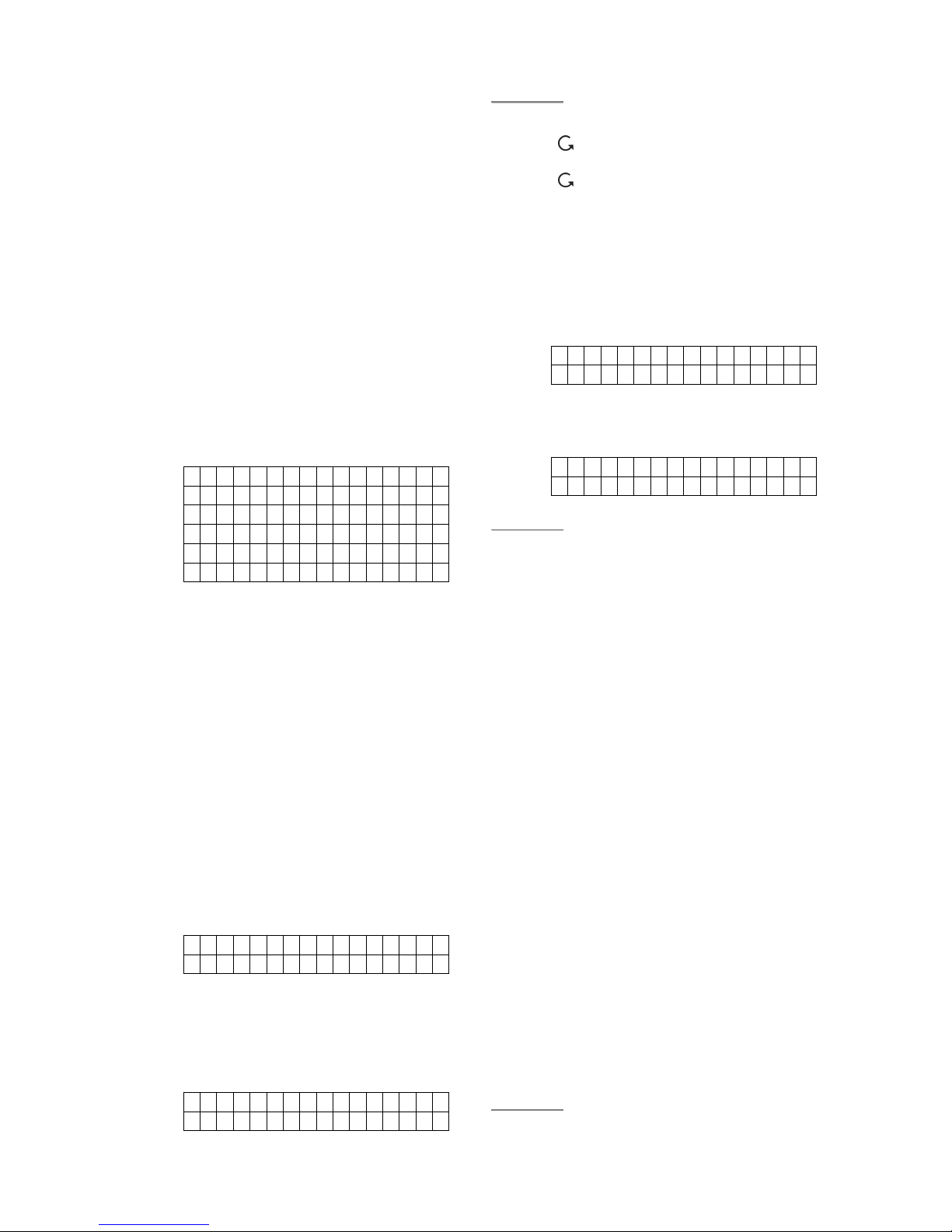
1 1
2 2ABCabc
3 3DEFdef
4 4GHIghi
5 5JKLjkl
6 6MNOmno
7 7PQRSpqrs
8 8TUVtuv
9 9WXYZwxyz
0 0<space>/-&’.”+
¿ ¿
# #
4
Delete character
and backspace
StepC11. Press “OK”, adding a RC is now
completed, screen returns to the
“Device +/-“ menu.
<<NNOOTTEE>>
) After a Remote Controller is added in,
you can use the Remote Controller to
arm/disarm the system. In addition,
pressing the “Panic” button for 3
seconds or twice within 3 seconds, the
Control Panel will generate a Panic
alarm.
) The “Panic“ alarm generated from the
Remote Controller will have to be
silenced at the Control Panel only.
See section “Stop the Alarm”.
) Press “ “, all the learning/setting
processes having done will be ignored,
the screen returns to “Device +/-
“ menu.
Other Devices
For Smoke Detector, Remote Keypad, Water
Sensor and Night Switch, no further option
needs to be specified, hence after it is detected,
a zone is assigned, and the zone name
entered, the following screen is displayed.
I n s t a l l e d : ( O K ? )
S D L i v i n g r o o m
Press “OK” to confirm, adding a smoke
detector, or a Remote Keypad or a Water
Sensor or a Night Switch is now completed.
Device Naming
Detectors can be given names and location
descriptions to help understand system events.
The devices can be named when first installing
them or by editing them afterwards, the
procedure is similar for both situations.
z When the “Enter zone Name” screen is
displayed, the keypad can be used to
enter text. Simply locate the
corresponding numeric keys to the desired
alphabets/symbols and press repeatedly
until the wanted alphabets/symbols appear.
Release the key and the flashing cursor
automatically jumps to the next position for
you to continue with the next letter by the
same method.
z The keys have the following functions:
z When the name is complete, press “OK”
to confirm and return to the previous or
main menu.
<<NNOOTTEE>>
) The name can be erased or clearing
the display by entering backward
spaces and pressing “OK”.
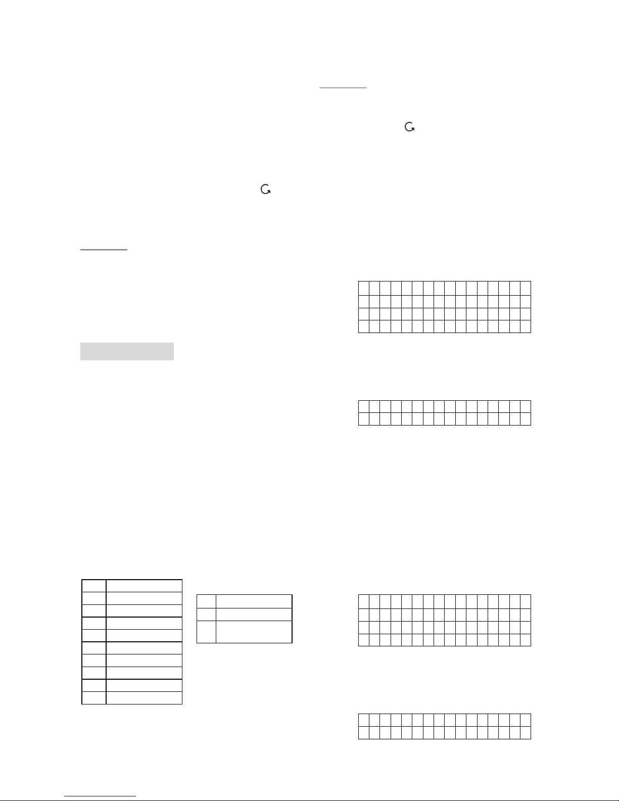
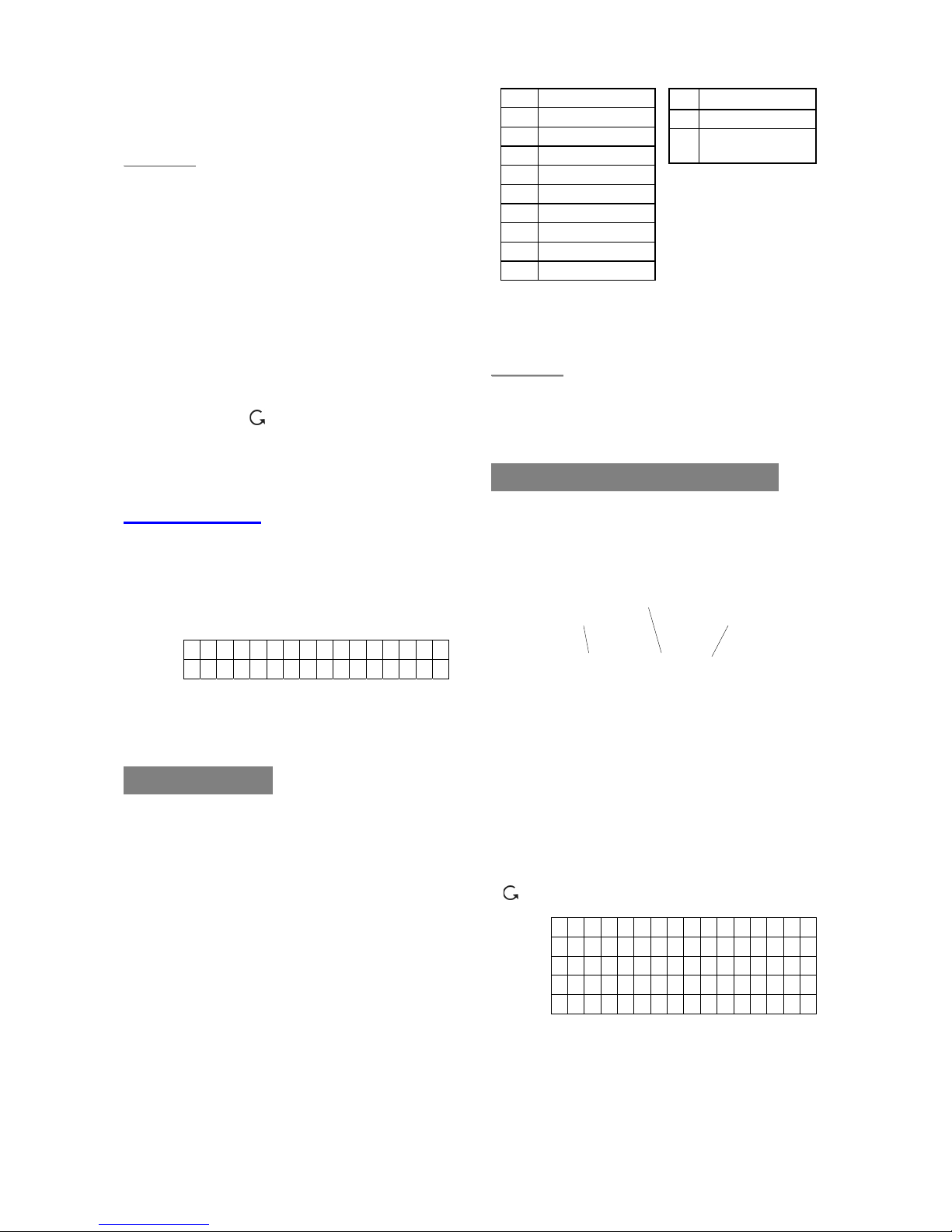
Device Display Nomenclature
The devices are displayed throughout the
menus and especially where there are zone
lists. The meanings of the display components
are shown in an example below:
The PIR detector is in zone 03, programmed
for burglar mode.
2. Edit Devices
To edit all the devices that have already been
installed, choose “Edit Devices” in the “Device
+/-“ menu, all the devices being included in the
system will be displayed. You may Press
“ “ to exit.
D C B a c k d o o r
IR Ha l l w a y
RC MR . S M I T H
S D K i t c h e n
Stop
Step1A. Use “S”,“T” keys to scroll the display
and choose the desired device for
editing. For DC, IR and RC, when
selected by pressing “OK”, the first
screen will ask if you want to change
the device attribute:
PIR Zone 03 B
Zone attribute
Zone number
Device type
CTC-1132 868AM 2007.07.18
21
B u r g l a r
H o me O mi t
H o me A c c e s s
E n t r Y
2 4 H o u r
F i r e
M e d i c a l E m g
Wa t e r
If no changes is wished here, press
“
“ to skip to Step 3A.
Step2A. Use “S”,“T” keys to scroll the display
and choose the desired device
attribute by pressing “OK”. The
screen will show:
Z o n e T y p e ? ( O k ? )
D C B a c k d o o r E
Step3A. Press “OK” to confirm. The next
screen will ask if you want to change
the name
P r o g r a m N a m e ?
B a c k d o o r
Step4A. Press “
“, if re-naming is not
required to exit to the previous device
list or press “OK” if you wish to edit
the zone name:
E n t e r N a m e + O k
. . . . . . . . . . .
Step5A. Edit the zone name and press “OK”
when completed to return to the
previous device list.
Step6A. Proceed to edit other devices or Press
“ ” to return to “Add/Delete Device”
menu.
To Edit Other Devices (SD/ KP/ WS/NS)
Step1B. Use “S”,“T” keys to scroll the display
and choose the desired device for
editing. When selected by pressing
“OK”, the first screen will ask if you
want to change the zone name. To
confirm, press “OK” or press “ “ to
exit.
P r o g r a m N a m e ?
B a c k d o o r
Step2B. Press “OK” if you wish to edit the
zone name:
Ent e r N a me + Ok
....... . . .
or press “ “ to exit to the previous
device list.
Step3B. Edit the zone name and press “OK”
when completed and return to the
previous device list.
Step4B. Proceed to edit other devices or Press
“ ” to return to “Add/Delete
Device” menu.
3. Remove Devices
Adding a device a second time is prohibited
unless it is removed from the system first. To
delete a device, choose “Remove Device” in
the “Device +/-“ menu
Step 1. Use “S”,“T” keys to scroll the display.
All the used zones with the device
names are listed in order of the zone
numbers.
D C B a c k d o o r
IR Ha l l w a y
RC MR . S M I T H
S D K i t c h e n
Step 2. Press “OK” when the required device
is chosen. The following prompt
message will be displayed for you to
reconfirm.
R e m o v e : ( O k ? )
RC MR.S M I T H
Step 3. Press “OK”. Deleting a device is now
completed. The screen returns to
previous device list.
<<NNOOTTEE>>
) If the selected sensor/zone is not what
you want to delete, press “ “ to exit,
the device list is again displayed for
you to make another selection.
) If “Remove Device” menu is chosen
while no device has been installed,
the display will show “No device
found in system” for 2 sec. and
return to the “Device +/- “ menu.
Step4. Proceed to remove other devices or
Press “ ” to return to “Add/Delete
Device” menu.
CTC-1132 868AM 2007.07.18
22
4. Program Siren
If an outdoor Bell Box, Indoor Bell Box or
Universal Receiver etc. is to be included in the
system, it should be programmed first by the
Control Panel, so that the Control Panel can
communicate with these auxiliary devices.
To program these auxiliary devices, select
“Program Siren” in the “Device +/-“ menu.
L e a r n S i r e n
S i r e n T a m p . O n
S i r e n T a m p . O f
C o n f i r m O n
C o n f i r m O f f
E n t r y S n d O n
E n t r y S n d O f f
R e c e i v e r 1
R e c e i v e r 2
z Learn Siren
z If there is any detector or Remote
Controller has been added already,
Step 1. Put all the desired Auxiliary devices
into learn mode (Refer to their
individual Operational Manual).
Step 2. Move the cursor to the position
“Learn Siren”.
Step 3. Press “OK”.
Step 4. The Control Panel will then sound a
long beep and transmit Learning code
to all devices simultaneously. The Out
Door Bell Box (BX-8) should respond
by activating its siren & strobe light
momentarily while the UR-7 status
LED lights up for 3 seconds.
Step 5. Place these auxiliary devices out of
Learn mode. Adding them into the
system is completed.
<<NNOOTTEE>>
) If any of these devices does not
respond, make sure that the device is
in learn mode and repeat the steps
again.
) After they are added in, every time
pressing a PIN code & followed by
“OK” key will result in the Control
Panel transmitting signal to all of them
) If there is no other detector or Remote
Controller being added first, the
following message will be displayed in
Step 3.
P l e a s e a d d
o n e d e v i c e
The message will be displayed for 2
sec. then the screen returns to
“Device +/-“ menu. You are
requested to add a detector or
Remote Controller first then you can
try programming these auxiliary
devices again.
<<IIMMPPOORRTTAANNTT NNOOTTEE>>
For the following options, whichever option
is selected, when the Control Panel
transmits the signal, all added sirens will
simultaneously received the signal and all
will acted accordingly
z Siren Tamp.On, Siren Tamp.Off
The Outdoor Siren BX-8tamper switch can
be enabled and disabled remotely. This is
used especially when replacing siren
battery.
z Disable the Siren tamper switch by
selecting “Siren Tamp.Off” and press
“OK”. All added sirens will
temporarity lose their Tamper
Protection simultanously
z Enable the Siren tamper switch by
selecting “Siren Tamp.On” and press
“OK”. All added sirens will be enabled
with the Tamper protection
simultanously.
<<NNOOTTEE>>
) The Siren tamper disable will
automatically revert to “On” after
about an hour if not switched back.
z Confirm On, Confirm Off
Both the Outdoor Siren BX-8 can be
enabled for arming and disarming
confirmation where beeps are emitted
from the Siren to validate that the system
has been armed and disarmed.
z Disable the Siren Confirmation by
selecting “Confirmation Off” and
press “OK”.
z Enable the Siren Confirmation by
selecting “Confirmation On” and

CTC-1132 868AM 2007.07.18
23
press “OK”.
z Entry Snd On, Entry Snd Off
The Outdoor Siren BX-8 can be enabled
or disabled from sounding the Entry Delay
warning beeps.
z Disable the Siren Entry Sound by
selecting “Entry Snd Off” and press
“OK”.
z Enable the Siren Entry Sound by
selecting “Entry Snd On” and press
“OK”.
z Receiver 1, Receiver 2
2 additional Universal Receivers can be
added to the system.
Step 1. Put Universal Receivers into learn
mode (Refer to their individual
Operational Manual).
Step 2. Move the cursor to the position
“Receiver 1”
Step 3. Press “OK”.
Step 4. The Control Panel will then sound a
long beep and transmit Learning code
to UR#1 simultaneously. The UR
status LED lights up for 3 seconds.
<<NNOOTTEE>>
) If Receiver 2 is also to be added to the
system, proceed to the following steps:
Step 5. Move the cursor to the position
“Receiver 2”.
Step 6. Press “OK”.
Step 7. The Control Panel will then sound a
long beep and transmit Learning code
to UR#2 simultaneously. The UR
status LED lights up for 3 seconds.
Step 8. Remember to put these Universal
Receivers out of Learn mode. Adding
them into the system is completed.
5. Edit Power Switch “Home Matic”
The controlpanel and powerswitch
communicate with each other by
following steps:
Step 1. Put the Power Switch “Home Matic” in
learning mode.
Step2. Put the Control Panel into
programming menu.
Step 3. Select Device +/- and then “Power
Switch” then the following screen will
be displayed.
Step 4. Select the disired channel number and
press OK.
Step 5. The control panel will sound one beep
and send a signal to the Power
Switch.
Step 6. Repeat Step 4 to learn other channels.
<<NNOOTTEE>>
) When the first (Channel 1) Power
Switch “HomeMatic” has been set,
and alarm is triggered, the LED of the
first Power Switch will flash (2-sec On
& 2-sec Off) automatically until the
Control Panel is disarmed.
) If the AC Fault exists in the Control
Panel and the alarm is trigger, the
LED of first (Channel 1) Power Switch
will flash slowly (2-sec On & 6-sec Off)
) Only the first (Channel 1) Power
Switch can flash during the panel
alarm.
VI. SMS Editor
For sending a SMS alarm reporting to your
mobile phone, edit your SMS message by
selecting “SMS Editor“ in Programming Main
menu.
E d i t S c r e e n
1. Editing SMS message
Step 1. During this display, compose your own
SMS message of up to 14x4=56
characters maximum. Press “OK” to
confirm.
The keypad can be used to enter text, similar
Channe l 1
Channe l 2
Channe l 3
Channe l 4
Channe l 5
Channe l 6
Channe l 7
Channe l 8
CTC-1132 868AM 2007.07.18
24
to the “testing” method being utilized for the
mobile phones
The keys have the following functions:
‘When the message is completed, press “OK”
to see the next display:
S a v e
Q u i t
Press “Save” to save the newly edited SMS or
exit this section back to Programming Menu by
press “Quit”.
Step 2. Press “OK” when the cursor is moved
to the choice of your decision.
When “Save” is chosen, the saved
SMS message will be sent when any
alarm is triggered and displayed again
on the LCD when the “SMS Editor” is
selected again.
VII. SMS Keyword
For sending remote commands to control the
operation of the Receiver 1 & 2 and Outputs
using SMS message, a personalized password
is required for CTC-1132 to recognize your
authority. To set a personalized keyword
different from “Pin Code” (factory default),
select “SMS Keyword“ in Programming Main
menu.
C h a n g e K e y w o r d ?
P i n c o d e + O K
1. Keyword Editor
Step 1. Press “OK” to confirm.
Step 2. The next display will prompt you to
enter your preferred “keyword” from
minimum of 1 character to a maximum
of 10-character and press “OK” when
done. .
K e y w o r d e d i t o r
....... . . . +OK
Step 3. The system returns to Main
Programing Menu automatically.
<<NNOOTTEE>>
) If there is no character entered, there
is no “Keyword” set up in the system.
) Without “Keyword” programmed in the
system, Remote Commanding of
CTC-1132’s Receivers and Outputs
via SMS will also be disabled..
VIII. Country Code
If the user send a SMS message ended by “00”,
CTC-1132 will study the telephone number
from the received message ,then, send a
confirmation message back.
However, each service provider may add
different pre-fix code in front of the telephone
number, which mostly is the country code.
Therefore, when CTC-1132 is sending the
confirmation message, the pre-fixed country
code may need to be delected in some cases.
So, if the confirmation message can be send
successfully, you can escape this section.
But, if the message sending is unsuccessful,
you will need to delect the pre-fixed country
code first.
Step 1. To enter the country code, press “OK”
for select Country Code menu then
press “OK” and the following screen
will appear. Key in user’s country
code then press “OK”.
Count r y C o de
....... . . . . . . ...
For example:
Norway’s country code is 47, so you
then type 47 under the country code.
It becomes as the following.
Count r y C o de
47..... . . . . . . ...
Step 2. Press “OK”. The next screen displays.
R e p l a c e m e n t
....... . . . . . . ...
Under most of the conditions, you will
1 1
2 2ABC(abc)
3 3DEF(def)
4 4GHI(ghi)
5 5JKL(jkl)
6 6MNO(mno)
7 7PQRS(pqrs)
8 8TUV(tuv)
9 9WXYZ(wxyz)
0 0<space>/-&’.”+:
* *
# #
S Backward space
T Forward space
4
Delete character
and backspace
CTC-1132 868AM 2007.07.18
25
not need to do the setting up for
Replacement. Just press “OK” and the
screen will automatically return to the
main Program selection list.
You can try to see if the confirmation
message has been successfully send
to you or not. If yes, escape this
section.
Step 3. If the message sending process is still
unsuccessful, please try to add an “0”
or “00” or any digits depeding on how
you normally dial your mobile phone
number in the replacement.
For Example:
R e p l a c e m e n t
0 . . . . . . . . . . . . . . .
Step 4. Press “OK” and the screen will
automatically return to the main
Program selection list.
Please try again to see if the
confirmation message has been send
successfully or not. If not, please go
back to Step 1 and change your
country code.
For example, for Norway, you can try
to type 047 instead of 47 in this case.
IX. GSM Signal
CTC-1132 utilizes GSM as its telephone
interface for communication purpose. The
GSM signal can be monitored by selecting
“GSM Signal” in the Programming Main Menu.
G S M S i g n a l
P l e a s e Wa i t
The current GSM signal strength in RSSI scale
( “0” ~ “9” with 9 being the highest strength
value) will be displayed on LCD and may
change due to change of environment.
G S M S i g n a l
G S M R S S I = 7
X. Walk Test
z When “Walk Test” is selected, the Green
& Yellow LED’s will flash 3 times with 3
beeps, and the following two test patterns
are displayed for 2 sec. each.
z Then the following message is displayed:
* Wa l k T e s t *
z Pressing the test button on the sensor or
any button on the Remote Controller or
triggering the sensor, if the Control Panel
received the signal, it will sound 2 short
beeps and the display will show you which
sensor with its zone number is reacting
and the RSSI strength.
I R Z o n e 0 2 D
Hallway R=09
z The message will be displayed for 30 sec.
or being replaced by another test signal.
z Pressing “ “ key, the screen will return
to “Walk Test” banner.
<<NNOOTTEE>>
) The function of showing its RSSI
strength (e.g. “R=09”) is only avaliabe
in 868 MHZ Control Panels.
z Exit “Walk Test”
z To e xi t “Walk Test” mode,
press ” “ key.
z If no test signals are received for 5
minutes, the Control Panel will exit
“Walk Test” mode and return to
“Alarm Off”. Press “OK” key to add
another 5 minutes.
XI. Reset GSM
GSM module will be reset once you have press
“OK”. Please wait for 1 minute for the reset
process to be activated.
CTC-1132 868AM 2007.07.18
26
Operation
I. Entering User Menu
When the system is in Disarmed mode (Alarm
off), entering a valid user code can access the
user menu, the system can then be Away
armed or Bypass armed via this menu.
When the first numberic key is pressed, the
display will show:
E n t e r C o d e
¿. . .
when the complete PIN code is keyed in
followed by “OK”, within 10 sec., the first two
lines of the user menu is shown:
A w a y A r m
H o me A r m
A flashing dot will appear next to “Away Arm”,
the complete menu list consists of:
A w a y A r m
H o me A r m
B y p a s s
L o g
Wa v e m a n
These items can be scrolled through by using
the “T”, “S” keys.
<<NNOOTTEE>>
) If there is any fault event occurred, no
matter if the fault condition has been
rectified or not, when you enter the
PIN Code followed by “OK”, the
following screen will be displayed.
F a u l t D s p
A w a y A r m
H o me A r m
B y p a s s
L o g
P o w e r S w i t c h
And the cursor stays at “Fault Dsp”
position. To arm the system, please
see the section “Forced Arming”
below.
) If there is any SMS message saved, the
screen will display SMS for SMS
message reading
) If you press “ ” while the “Alarm off”
is displayed, a “Enter Code” promp
screen will be displayed. After you
enter your pin Code, the above screen
will also be displayed.
) After 30 seconds of key-inactivity, the
system will automatically exit User
Menu and return to “Alarm off” mode.
II. Away (Alarm ON) Mode
1. Arming the system
If the system is in Disarmed mode (Alarm off),
to arm the system.
Step 1. Enter your PIN code and press “OK”.
The display will show:
Away A r m
Home A r m
Bypas s
Log
Wavema n
and the cursor stays at “Away Arm”
Step 2. Press “OK” and the screen will display.
T i me T o E x i t
3 0 s e c
The defined EXIT Delay is displayed on the
second line, and is counting down. During the
EXIT Delay period, the exit sound plays, unless
it has been chosen to switch off.
Step 3. When the Exit Delay time is up, or the
“Entry” Door Contact (Final Door Set
Function programmed to be “On”) is
closed, the Control Panel will sound a
long beep. The “Alarm On” will
display on the screen and the system
is in Arm mode.
Alarm O N
07: 25 1 6 D ec
<<NNOOTTEE>>
) When “Final Door Set Option” is set to
“Off”, the Control Panel enters “Alarm
On” mode only when the Exit Delay
time is up.
) The Control Panel has “Screen Save”
function. The “Alarm on” message
will be displayed for 160 sec. only.
Afterwards only current date & time is
displayed on the second line.

CTC-1132 868AM 2007.07.18
27
) The system can also be armed by using
the Remote controller (Optional).
2. Stopping the Exit Delay
The Exit Delay can be stopped by disarming
the system.
Step 1. Press “ “
Step 2. The screen will ask you to enter the
PIN code. In addition, the counting
down Exit Delay is displayed on the
left side of the 2
nd
line.
Step 3. Enter your PIN code and then press
“OK”. “Alarm Off” will be displayed
on the screen and the system returns
to Disarmed mode.
<<NNOOTTEE>>
) The Exit Delay can also be stopped by
pressing the “Disarm” button on the
Remote Controller (Optional).
) If the Exit Delay period times out before
the code can be entered, the system
will be armed.
3. Extend the Exit Delay
During the Exit Delay period, the delay time
can be extended by pressing the “ARM” button
on the Remote Controller (Optional). Each
time the “ARM” button is pressed, the delay
time starts counting from the beginning. ( To do
this, press and hold th ARM button for 1
second and you will hear a long beep to
confirm the extention of Exit time).
<<NNOOTTEE>>
) While you arm the system, if a Door
Contact or PIR sensor has been
triggered (eg. Door is open), arming is
also prohibited. To arm the system,
please see the section “Forced
Arming” below.
III. Forced Arming
z While you try to arm the system by
entering the PIN Code, if there is any fault
situation has occurred before, the display
will show.
F a u l t D s p
A w a y A r m
z If you move the cursor to “Away Arm”
position and then press “OK”, the Control
Panel will sound a ding-done warning
sound to indicate arming is prohibited, and
the message “Fault DSP” is displayed in
the middle of the top display row and
alternates at 2-second intervals with
individual fault events.
<<NNOOTTEE>>
) In the same situation, if you arm the
system by pressing the “Arm” button
on the Remote Controller, the Control
Panel will response in the manner as
described above and the arming is
also prohibited.
z You will need to press “ “ to return back
to Alarm Off Screen.
z At this moment, you can first rectify all of
the problems and then clear the “Fault
display” (Please see section XI “In a
Fault Situation”), and then afterwards you
can arm the system.
z However, if you want to put the system
into Arm mode with the fault situation
persisting, it is still possible by following
the steps below to execute “Forced
Arming”.
Step 1. Enter your PIN Code and press “OK”,
a prompt message will be displayed.
For ce A r m
( O k ? )
Step 2. Press “OK” to double confirm.
Step 3. The Exit Delay counting down screen
is displayed as in above section.
Step 4. When the Exit Delay time is up, the
Control Panel will sound a long beep.
The “Alarm On” will display on the
screen and the system is in Arm mode.
<<NNOOTTEE>>
) Any time pressing “ “ followed by “PIN
Code” and “OK”, the screen returns to
“Alarm Off”
) The “Fault DSP” screen has a time-out
for 5 minutes. It will automatically exit
and return to “Alarm Off” screen after
5 minutes.
) If a sensor is by-passed (Please see
section “Partial Arm mode”, the fault

CTC-1132 868AM 2007.07.18
28
condition of that sensor will not be
checked.
) If a sensor tampered or out-of-order
occurs, you can temporarily by-pass it
or permanently remove it.
Arming with Door Opened
z
While you arm the system, if any door was
detected to be open, the Control Panel will
also sound a ding-dong warning sound to
indicate arming is prohibited. The
message “Fault DSP” is displayed in the
middle of the top display row and
alternates at 2-second intervals with the
sensor name that is being triggered.
z At this moment, you can close the opened
door, after which the fault display will be
cleared automatically and the screen
returns to “Alarm off”. You then can arm
the system again.
z However, if you want to put the system
into Arm mode with the opened door, it is
still possible by following the Steps
described above to execute ”Forced
Arming”.
IV. Disarm (Alarm off) mode
Disarming the system
To disarm the system
If the system is in either the Away Arm mode or
Home Arm mode (Alarm ON), enter your pin
Code and press “OK”. If the PIN code is
correct, the Control Panel will sound 2 short
beeps and return to Disarmed mode. The
screen will show.
A l a r m O f f
0 6 : 4 3 0 1 J a n
<<NNOOTTEE>>
) When the system is Home Armed,
pressing the “DISARM” button on the
Remote Controller will disarm the
system.
) When the system is Away Armed,
pressing the “DISARM” button on the
Remote Controller can disarm the
sytem when either an “Entry” device
has been triggered, or when the
“Remote Controller Entry Enable”
has been set to “ON”.
V. Home Arm Mode
The Home mode allows the home to be Armed
so that no one can get inside without first
Disarming the system, yet the person already
inside the house can move freely without self
triggering the alarm.
<<NNOOTTEE>>
) You can enter the HOME mode only
when the system is in DISARMED
mode.
1. Entering Home Mode:
Step 1. When the system is in Disarmed mode,
key in your Pin Code then press “OK”.
Step 2. Press “ T “ to move the cursor down to
select “Home Arm”.
Step 3. Press “OK” and the screen will display.
T i me T o E x i t
3 0 s e c
The defined EXIT Delay is displayed on the
second line, and is counting down. During the
EXIT Delay period, the exit sound plays, unless
it has been chosen to switch off.
Step 4. When the Exit Delay time is up, the
Control Panel will sound a long beep.
The “Home” will display on the screen
and the system is in Home Arm mode.
<<NNOOTTEE>>
) The system can also be armed by using
the Remote controller (Optional).
Step 5. Press “OK” and the screen will display.
Home
08: 00 1 6 D ec
2. Stopping the Exit Delay
The Exit Delay can be stopped following the
steps described in “Stopping the Exit Delay”
in section II, “Away Mode”
3. Extend the Exit Delay
The Exit Delay can be extended following the
steps described in “Extend the Exit Delay” in

CTC-1132 868AM 2007.07.18
29
section II, “Away Mode”
4. Forced Arming
z
If there is any fault condition has occurred
or a door was found opened before or any
sensor is triggered, when you press “OK”
in step 3 above or when you press
“Home” button on the Remote Controller,
the Control Panel will sound a ding-dong
warning sound to indicate entering the
Home mode is prohibited. You rectify the
problem first, then clear the fault display,
and then try again. Or you can do forced
arming to enter Home mode compulsorily.
Please follow the instructions described in
“Forced Arming” in Section III.
VI. Partial (By-pass) Arm Mode
The Partial (By-pass) Arm mode allows the
user to de-activate (by-pass) any sensors at
their discretion. This feature allows your home
to be armed; yet the person inside the house
can move freely in the area where the sensor
is by-passed.
To put the system into the Partial (Bypass) Arm mode:
Step 1. Enter your PIN code and press “OK”
within 10 seconds. The display will
show:
A w a y A r m
H o me A r m
B y p a s s
Step 2. Press “T “ to move the cursor down to
select “Bypass”.
Step 3. Press “OK”
Step 4. All the zones are listed in zone number
order.
D C B a c k d o o r
I R H a l l w a y
D C F r o n t d o o r
I R L i v i n g r o om
RC MR . S MI T H
Stop
Step 5. Press “T”, “S” keys to select the zone
to be by-passed.
B y - p a s s : ( O k ? )
D C B a c k d o o r
Step 6. Press “OK” to confirm the selection.
The selected zone will be marked with
a “¿” character in front of it to indicate
that device is to be by-passed.
<<NNOOTTEE>>
) The zones can be toggled between by-
passed and not by-passed by
pressing the “OK” key repeatedly
followed by the “¿” character
appearing for By-pass setting and “¿”
character disappearing for By-pass
unsetting.
Step 7. You can repeat Step 5 ~ Step 6 to
continue selecting the device to be bypassed.
Step 8. After all the sensors to be by-passed
have been selected, press “ “ to
return to user menu and the cursor
stays at “Arm”.
Step 9. Press “OK” to select “Arm” and to arm
the system.
<<NNOOTTEE>>
) If a sensor is by-passed, then the
Contorl Panel will not respond to its
triggering in Arm mode.
) The by-pass setting is effective for only
one time, once the system is disarmed,
the by-pass setting is cleared
automatically.
) When a sensor is by-passed, the
system can be armed directly
regardless of its fault situation (if any).
However, its fault situation is still being
monitored and will be logged and
displayed when you access the “Log”
submenu.

CTC-1132 868AM 2007.07.18
30
VII. Alarm Activation
For Alarm Activation by Events and Control Panel Responses, please refer to the following table:
Control Panel Mode & Response Table
Type of
Alarm
Alarm
Abbr
Disarmed Away Arm Home Arm Exit
Away Arm
Entry
Home Arm
Entry
Burglar “B”
No
Response
Instant
Burglar
Alarm
Instant
Burglar
Alarm
No
Response
No
Response
No
Response
Home
Omit
“O”
No
Response
Instant
Burglar
Alarm
No
Response
No
Response
No
Response
No
Response
Home
Access
“A”
No
Response
Instant
Burglar
Alarm
Start Entry
Timer
No
Response
No
Response
No
Response
Entry “E”
No
Response
Start Entry
Timer
Start Entry
Timer
No
Response
No
Response
No
Response
Delay “D”
No
Response
Instant
Burglar
Alarm
Instant
Burglar
Alarm
No
Response
No
Response
No
Response
24 HR. “H”
Burglar
Alarm
Burglar
Alarm
Burglar
Alarm
Burglar
Alarm
Burglar
Alarm
Burglar
Alarm
Medical “M”
Emergency
Alarm
Emergency
Alarm
Emergency
Alarm
Emergency
Alarm
Emergency
Alarm
Emergency
Alarm
Fire “F”
Fire Alarm Fire Alarm Fire Alarm Fire Alarm Fire Alarm Fire Alarm
Water “W”
Water Alarm Water Alarm Water Alarm Water Alarm Water Alarm Water Alarm

CTC-1132 868AM 2007.07.18
31
VIII. Stop the Alarm and Alarm
Display
During any alarm, the Control Panel wil sound
its siren and report to the Phone number
programmed previously. The display will show
as below:
A L A R M ! A L A R M !
A L A R M ! A L A R M !
1. Stopping the Alarm
During an alarm, to stop the siren and clear
display:
Step 1. Key in your PIN code, followed by
“OK”.
<<NNOOTTEE>>
) if you press any key other than the first
digit of your PIN code, the screen will
prompt you to enter your PIN code.
Step 2. If the PIN code is correct, then the
alarm sounding will be stopped.
If the alarm is stopped before reporting
process begins:
Step 3A. The screen will show you which
device that triggered the alarm with
its zone number displayed:
A l a r m S t a r t e d B y
0 1 ). I R H a l l w a y
Step 4A. Press “OK”
Step 5A. If there are more than one alarm
events have been raised, the
Control Panel continues displaying
the 2nd alarm event with “02).”
Stating at the beginning of the 2nd
line.
Step 6A. Repeat pressing further keys until all
the alarm events are displayed
thoroughly then the display will show:
S y s t e m r e a c h e d
N o n e
Step 7A. Press “OK”, the display returns to
“Alarm off”.
<<NNOOTTEE>>
) Press “ “ or no key is pressed within
5 sec. the screen returns to 1
st
device
display. You can repeat from the
beginning to view the alarm event one
more time.
) No alarm reporting will be made.
However one “OPEN” report by the
user will be reported.
If the alarm is stopped before reporting
is finished:
Step 3B. The screen will show you which
device triggered the alarm with its
zone number displayed:
A l a r m S t a r t e d B y
0 1 ). I R H a l l w a y
Step 4B. Press “OK”
Step 5B. If there are more than one alarm
events have been raised, the
Control Panel continues displaying
the 2nd alarm event with “02).”
Starting at the beginning of the 2nd
line.
Step 6B. Repeat pressing further keys until all
the alarm events are displayed
thoroughly then the display will show:
S y s t e m r e a c h e d
None
Step 7B. Press “OK”, the display returns to
“Alarm off”.
If the alarm is stopped after reporting
has been finished,
Step 3C. The device that triggered the alarm
with its zone number is displayed.
A l a r m S t a r t e d b y
0 1 ). I R H a l l w a y
z Proceed to display the alarms and clear
the alarm displays as specified in Step 4A
~ Step 6A in previous section.
Step 4C. After all the alarm events are cleared,
then the display will show:
S y s t e m r e a c h e d
269406 6 7

CTC-1132 868AM 2007.07.18
32
Step 5C. Press “OK”, the display returns to
“Alarm off”.
<<NNOOTTEE>>
) When an alarm (other than Panic Alarm)
is raised, press the “Disarm” button
on the Remote Controller will also
stop the alarm (Optional).
) Panic Alarm must be silenced at the
Control Panel. This is to prevent the
Remote Controller from being
snatched from the user and silence
the alarm using the Disarm button.
2. Alarm memory
If an alarm was raised without being silenced
during your absence, and the alarm reporting
has been carried out; the screen will stay on
the ”Alarm warning” display.
A L A R M ! A L A R M !
A L A R M ! A L A R M !
z When you come back and disarm the
system by pressing the DISARM button on
the Remote controller, the “Alarm
warning” display still remains unchanged.
z To clear the display, follow the same steps
as “Stopping the Alarm“ described above,
you can see the source of the alarm.
z If more than one alarm events including
“Device Tampered” have occurred,
repeated pressing further keys, the alarm
events will be displayed one by one
sequentially until all events have been
displayed, then the screen returns to
“Alarm off”.
IX. Event Log
The alarm log memorises the last 20 system
events including
9 All Alarm Events with Device ID
9 All Fault Warning Events
9 All Arming And Disarming Events
9 Remote Control Event
z The logged events are displayed in
reversed chorological order, (most recent
event first).
z The log is marked with a “Start” label
before the most recent entry and “End”
after the oldest entry.
z To View Log:
Step 1. Key in the user code and press “OK”
while in Disarm mode to access
User’s Menu.
Step 2. Press the “T” key repeatedly to select
“Log” and then press “OK” and the
start of the log will be displayed.
S T A R T
0 8 : 0 2 1 6 D e c
Step 3. The log can now be scrolled up and
down and viewed with the “S”, “T”
keys; the most recent event will be at
the start.
Step 4. An example of logged event is given
below; where the first line tells the
time and date of the event, the second
line tells the type of event and the
third line either states the User or the
device that caused the event.
Abbreviation as “DC” stands for Door
Contact, “LB” is short for low battery,
“Tamp” means Tamper where “Rest”.
is short for restore.
0 2 : 3 8 0 1 J a n
Di sar m
User 1
0 2 : 4 0 0 2 J a n
Pa n i c
D A V I D R C
X. Power Switch “Home Matic”
Step 1. Select the funtion of “Power switch”
then the following screen will be
displayed.
Cha n ne l 1
Cha n ne l 2
Cha n ne l 3
Cha n ne l 4
Cha n ne l 5
Cha n ne l 6
Cha n ne l 7
Cha n ne l 8
Step 2. Select the desired Power Switch
(Channel number) and then press
“OK” .

CTC-1132 868AM 2007.07.18
33
T u r n O n
T u r n O f F
If the user choose to Turn On the
power switch, then, power switch will
automatically power on and activated.
On the other hand, if the user choose
Turn off, then power switch will be
power off and deactivated.
The user can set any of those eight
power switch freely according to their
own need.
<<NNOOTTEE>>
) When the user is turning the power
switch “Home Matic” modules
ON/OFF from CTC-1132 panel, they
should wait for at least 4 seconds
between each operation.
XI. False Alarm Management
CTC-1132 has a regulatory false alarm
management facility built-in:
9 Dual-Ply Entry Wanring
9 Sequential Verification Alarm
Reporting
1. Dual-Ply Entry Warning
z This is to warn the user that an alarm
report to the Emergency Phone Numbers
is about to be made
z When a zone that is not programmed for
delay is violated during the Entry Delay, or
the correct PIN code was not entered
within the programmed Delay period, a 30sec internal alarm is given before an alarm
report is made.
z If a valid user PIN code is entered within
the 30 seconds, the alarm will be aborted
and the system returns to normal status.
z If no valid user PIN code is entered, a
burglar alarm will be sent.
2. Sequential Verification Reporting
z A sequential verification alarm report is
generated when a second alarm from a
different Burglar Door Contact or Burglar
PIR is registered within a 30-min period.
z This Sequential Verification Report will be
sent in addition to the alarm report.
z Alarms cannot be verified after the Entry
Delay has been initiated.
XII. Faulty Situations
z The Control Panel is capable of detecting
following fault events:
9 Control Panel Low Battery
9 AC Power Fail
9 Sensor Out-of-order
9 Sensor Low Battery
9 Device and Control Panel
Tamper
9 Interference Detection
9 GSM isn’t ready
9 GSM PUK
9 GSM PIN Code
z In case any fault condition is detected, the
Control Panel will respond with a “Fault”
display and/or “Fault” alarm respectively
according to the nature of the faulty event.
z Device Sabotaged
The Control panel, Door Contact,
Remote Keypad & PIR sensors are
“Tamper” protected.
Control Panel
A Tamper switch protects CTC-1132
from any removal attempts away
from its cross mounting bracket
Another Tamper switch protects the
Power Supply Lid from being opened
or removed.
PIR Sensor
z For IR-7 & 8
A Tamper switch protects the
enclosure from being opened.
z For IR-9
A Tamper switch protects the
enclosure from being opened.
A Back-Tamper protects the unit from
being removed from its mounting site
Door Contact
A Tamper switch protects the

CTC-1132 868AM 2007.07.18
34
enclosure from either being opened
or being removed from the mounting
surface.
z Sensor Low battery
If the battery voltage of PIR sensor, Door
Contact, Remote Keypad, Water Sensor,
Remote Controller or Smoke Sensor is
low, a “Sensor Low Battery” message will
be detected.
z Sensor out-of-order
After installation of the PIR sensor, Door
Contact, Water Sensor or Smoke Sensor,
a periodic supervision signal will be
transmitted at intervals between 60 min.
to 100 min.
If the Control Panel did not receive the
signals transmitted from any individual
sensor for a period of preset supervision
timer Hours Hours, a “sensor out-of-
order” fault event will be detected and
displayed.
z Interference
CTC-1132 can detect interference on both
433 Mhz and 868 Mhz frequency band.
After a continuous interference signal is
present for more than 30 seconds, an
interference event can be logged,
reported and displayed on the LCD (if
Fault Display submenu is chosen).
z GSM isn’t ready
If the SIM card is found missing, a
warning message will be generated.
Panel SIM Card?
This indicates that you need to insert
the GSM SIM Card. Please refer to
Page 16, IV Special Settings,
Section 14.
Panel GSM PIN Code
You will need to set up your own
PIN code.
Panel GSM Signal?
Please change the position of CTC1132 control panel to get better
GSM signal.
Panel GSM Fault
Please re-start your CTC-1132
control panel
Panel GSM PUK?
SIM Card has been locked, please
call your service provider for help.
1. Fault Message Display
z When any fault situation persists, the
Control Panel will respond as below when
it is in Disarmed mode:
The Yellow LED will light to indicated
the fault condition
The LCD will display the type of fault
and the source of the fault in the
“Fault Display” section of the User
Menu.
A warning beep will sound at every
30 seconds.
If a fault condition is detected while
the system is in full arm mode, the
fault event display will not be
generated until the system is
disarmed.
2. Clearing Fault Message Display
z The Yellow LED will turn off automatically
once all of faulty conditions are restored, or
any faulty devices are removed. It cannot
be cleared manually.
z On the contrary, the fault message display
retains even if the faulty conditions have
been restored.
z The fault message can only be cleared
manually after the fault condition has been
rectified.
3. Viewing/Clearing the Fault
Message
To check what the fault condition is,
Step 1. When the system is in Disarmed mode.
Enter your PIN Code followed by “OK”.
Step 2. The screen will display
F a u l t D s p
Arm
and the cursor stays at “Fault Dsp”
Step 3. Press “OK” to select “Fault Dsp”
Step 4. All the fault events are listed. Use
“S” ,”T” key to move the cursor
downwards or upwards. The screen

CTC-1132 868AM 2007.07.18
35
is also scrolled down or up
respectively.
Step 5. After viewing all the fault events, press
“ ” key, a prompt message is
displayed.
C l e a r F a u l t
D s p : ( O K ? )
Step 6. After the fault condition has been
rectified, press “OK” and the fault
event will be cleared and the screen
returns to “Alarm off”.
<<NNOOTTEE>>
) In Step 6, if “ “ key is pressed, the
screen returns to “Alarm off”, and the
Yellow LED stays on, the Control
Panel keeps sounding a short beep
every 30 seconds, and the fault event
display retains.
) If the fault condition has not been
rectified, the fault event display will not
be cleared. It will come on again
while you try to arm the system and
the faulty condition inhibits the system
from being armed, the fault message
will be displayed again. The fault
event display can be cleared only after
the fault condition has been rectified.
) Even when the fault messgae is cleared,
the fault event will still retained in the
“Log”.
4. Fault Event Response
z When a fault condition is detected, in
addition to the fault display, the Control
Panel will also respond separately
according to the nature of the fault event.
AC Power Fail
Only the yellow LED will light and
the fault message will be displayed,
no further action will be taken.
Control Panel Low Battery
Any time the Panel battery Low is
detected, yellow LED will light while
this fault message can be viewed
on LCD under “Fault Display”.
Panel Sabotaged
If the Tamper switch on the Control
Panel is triggered while the system
is in Armed and/or Home mode, the
Control Panel will sound an audible
alarm and report “Burglary” alarm.
While if the system is in Disarm
mode, no alarm will be generated.
Sensor Low Battery
If the low battery is detected on any
sensor, yellow LED will light up at
any time while its fault message
can be viewed on LCD under
“Fault Display”.
Sensor Sabotaged
If the Tamper switch on the PIR
Sensor or Door Contact is triggered
while the system is in Arm & Home
mode, the Control Panel will sound
an audible alarm and report
“Burglary” alarm .
While if the system is in Disarm
mode, no alarm will be generated.
Sensor out-of-order
The PIR Sensor, Door Contact,
Water Sensor and Smoke Detector
will send supervised-signal to the
Panel at intervals between 60~100
min. The system will according to
the setting of the supervision send
report.
When the Control Panel cannot
receive the supervised signal from
the device for preset supervisory
period, the Control Panel will
sound an audible alarm and yellow
LED will light while this fault
message can be viewed on LCD
under “Fault Display”.
<<NNOOTTEE>>
) The supervision function activates in
Arm/Home/Disarm Mode.
) For Setting Supervision, please refer to
IV. Special Setting 13. Supervision.
While the system is in Disarmed
mode, no alarm event will be
generated.
Interference
When the system is programmed
with Interference Detection On, and
when there is an interference

CTC-1132 868AM 2007.07.18
36
detected for 30 seconds, the yellow
LED will light up and the fault
message can be viewed under the
“Fault Display”..
5. Fault Message Nomenclature
z The fault event message is displayed in
short form as below:
Fault Condition
―
Message displayed
Interference
―
“Interference”
AC Power Fail
―
“AC failure”
Control Panel low
battery
―
“Panel L.B.”
Control Panel
sabotaged
―
“Panel Tamper”
Sensor Low Battery
―
(Sensor w/ Zone
Name) + “L.B.”
Sensor Sabotaged
―
(Sensor w/ Zone
Name) + “Tam per ”
Sensor out-of-order
―
(Sensor w/ Zone
Name) + “out”
GSM out of Signal
―
“GSM Signal”
GSM module missing
―
“GSM Missed”
GSM Pin Code,
Incorrect/missing
―
“GSM Pin Code”
GSM locked by PUK
―
“GSM PUK”
SIM Card missing
―
“GSM isn’t Ready”
<<EEXXAAMMPPLLEE>>
If “DC Z 01 L.B.” is displayed, it means
Zone 1 Door Contact is low battery.
<<NNOOTTEE>>
) While you arm the system, if any of
Door Contact or PIR is triggered,,
arming is also prohibited and the
sensor triggered will be displayed as
fault message.
Sensor triggered Message displayed
Door Contact
triggered
(DC w/ Zone Name) +
“open”
PIR triggered
(IR w/ Zone Name) +
“Active”
6. Remote Control Command
The Unit can be controlled by Remote Control
Commands sent via SMS messages.
A. From Regular Phone Lines
Step 1. Dial the GSM phone number of your
Control Panel and hang up on the first
ring.
Step 2. Dial the Control Panel again after
8~20seconds.
Step 3. You will hear 2 beeps from the Control
Panel via phone set.
Step 4. Enter the user pin code (user 1 ~ user
4).
Step 5. If the pin code is correct, you will hear
2 beeps from the Control Panel via
phone set.
<<NNOOTTEE>>
) In Step 5, the first digit of pin code
should be entered within 3 sec.
) In Step 5, a valid pin code should be
entered with 20 sec. otherwise the
Panel will hang up automatically.
Step 6. Enter the 2-digit DTMF Control
Command. When the Command is correct,
you will hear 2 beeps; if the Command is
uncorrect, you will hear 1 beep.

CTC-1132 868AM 2007.07.18
37
z DTMF Remote Control Command Table
Control Command Result
00
Hang up the phone
10
Disarm
11
Arm
20
UR#1 deactivate
21
UR#1 activate
30
UR#2 deactivate
31
UR#2 activate
B. Via SMS message
Remember to change the Language
setting of your mobile phone to English
before proceeding.
z SMS Remote Control Command Table
Control
Command
Result
00
Hang up with Confirmation
10
Disarm
11
Arm
20
UR#1 deactivate
21
UR#1 activate
30
UR#2 deactivate
31
UR#2 activate
510
1
st
Power Switch Close
520
2
nd
Power Switch Close
530
3
rd
Power Switch Close
540
4
th
Power Switch Close
550
5
th
Power Switch Close
560
6
th
Power Switch Close
570
7
th
Power Switch Close
580
8
th
Power Switch Close
51101~51199
1
st
Power Switch Open for 1
Hour to 99 Hours
52101~51199
2nd Power Switch Open for 1
Hour to 99 Hours
53101~51199
3
rd
Power Switch Open for 1
Hour to 99 Hours
54101~51199
4
th
Power Switch Open for 1
Hour to 99 Hours
55101~51199
5th Power Switch Open for 1
Hour to 99 Hours
56101~51109
6
th
Power Switch Open for 1
Hour to 99 Hours
57101~51109
7
th
Power Switch Open for 1
Hour to 99 Hours
58101~51199
8
th
Power Switch Open for 1
Hour to 99 Hours
<<NNOOTTEE>>
) 5-digit Control Command Format:
C C C D D
The Number of
the Power switch
Open-period
for hour
CCC = The Number of the Power switch. E.g.
(511) is the 1
st
Power switch, (521) is the 2nd
Power switch
DD= Open-period for hour, (01) is Power switch
open for one hour, (99) is Power switch open for
99 hours.
NOTE! Enter a space between each command.
) If you set the open-period for 2 hours, it
means when the Panel receives the
command, the power switch will turn on
for 2 hours and turn off after 2 hours.
<<EEXXAAMMPPLLEE::>>
A. For 2-digit Remote Control Command
z Send the SMS message to command
the Unit to enter Arm Mode and send a
confirmation SMS back to your mobile
phone. The format is:
M I C H A E L *
1 2 3 4
1 1 0 0
The
programmed
SMS keyword
User
PIN
Code
Remote
Control
Command

CTC-1132 868AM 2007.07.18
38
<<NNOOTTEE>>
) A confirmation SMS message will read
on your mobile phone as:
“Confirmation, MICHAEL* 1234 11 00”
z Send the SMS message to command
the Unit to enter Arm Mode without a
confirmation SMS back to your mobile
phone. The format is
M I C H A E L *
1 2 3 4
1 1
The
programmed
SMS keyword
User
PIN
Code
Remote
Control
Command
B. For 3-digit Remote Control Command
The 3-digit Remote Control Command is
used for turning off the Power switch.
z Send the SMS message to command
the Unit to turn off the Power switch #
1, and send a confirmation SMS back
to your mobile phone. The format is:
J O E 1 2 3 4 5 1 0 0 0
The programmed
SMS keyword
User PIN
Code
Power
switch
Number
<<NNOOTTEE>>
) A confirmation SMS message will read
on your mobile phone as:
“Confirmation, Joy 1234 510 00”
z Send the SMS message to command
the Unit to turn off the Power switch #
1 without a confirmation SMS back to
your mobile phone. The format is
J O E 1 2 3 4 5 1 0
The programmed
SMS keyword
User PIN
Code
Power switch
Number
C. For 5-digit Remote Control Command
z Send the SMS message to command
the Unit to turn on the Power switch #
1 for 1 Hour and than turn off, and
send a confirmation SMS back to your
mobile phone. The format is:
J O E 1 2 3 4 5 1 1 0 1 0 0
The
programmed
SMS keyword
User
PIN
Code
Power
switch
Number
Time
<<NNOOTTEE>>
) A confirmation SMS message will read
on your mobile phone as:
“Confirmed, Joy 1234 51101 00”
z Send the SMS message to command
the Unit to turn on the Power switch #
1 for 1 Hour and than turn off without a
confirmation SMS back to your mobile
phone. The format is:
J O E 1 2 3 4 5 1 1 0 1
The programmed
SMS keyword
User PIN
Code
Power
switch
Number
Time
XIII. Dialing & Call
Acknowledgment
1. Auto Dialing
z If the system is in Arm mode, when an
alarm occurs, the Control Panel will
immediately dial the phone numbers you
preset and play the recorded messages.
z If the system is in Home mode or
Disarmed mode, when an audible alarm is
initiated, the Control Panel will wait 15
seconds and then dial the phone numbers.
z After dialing, the Control Panel will delay 5
seconds then starts to play the message.
It firstly played the general part of the
recorded message (address) then plays
the specific alarm message (Burglar, Fire,
Medical or Panic) depending on the nature
of the alarm.
z To ensure the call is successfully received
by the recipient, the recipient should
acknowledge the message by pressing the
appropriate button on his telephone set.
z The Control Panel, while playing the
message, will check if there is any

CTC-1132 868AM 2007.07.18
39
acknowledgement signal being received. If
the recipient does not acknowledge the
call, the message will be repeated for a
period of 80 seconds; the Control Panel
will then consider the call as unsuccessful
and will try to dial the next phone number
in priority.
z If more than one number is programmed
the Control Panel will continue to dial the
number(s) until two emergency calls are
successfully answered with either keys or
“0”, or closed down with a key “9”
acknowledgement.
<<NNOOTTEE>>
) CTC-1132 Auto-Dialling features only
operate under Tone-Dialling method.
2. Call Acknowledgment
z If the recipient successfully receives the
call, the recipient should acknowledge it by
pressing the DTMF "0" or "9" button on
the telephone set..
Acknowledging with signal 0
If the recipient presses "0" on the phone
set as the acknowledging signal. The
Control Panel will take the following
actions.
9 The Control Panel will go back
on-hook.
9 The Control Panel will continue
alarming.
9 The Control Panel will try to dial
the phone numbers of the next
priorities until two recipients
have acknowledged the call.
Acknowledging with signal 9
If the recipient presses "9" on the phone
set as the acknowledging signal, the
following will happen:
9 The Control Panel will go back
on-hook.
9 The Control Panel will stop
alarming and stop dialing.
3.Auto Redial
z When only one Emergency phone number
is stored and that number is engaged, the
Control Panel will automatically redial that
number up to maximum of 5 times with an
interval of 62 sec. between dialing
attempts.
z When more than one telephone numbers
are stored, the Control Panel will dial in
accordance to the set priority order. If the
number being dialed is engaged, it will try
the next number. Each number will be
tried a maximum of 5 times and the redial
interval between each number is 5 sec.
z The maximum number of times the Control
Panel will retry is 15 times.
<<NNOOTTEE>>
) If no phone Number is programmed,
the Control Panel will not dial.
)
When dialing a pager number, the
Control Panel will only send the
identity code, it will not play the
message and the call is not
considered to be successful.
) The same pager number will be dialed
only once.
FCC Statement
This device complies with Part 15 of the FCC Rules. Operation
is subject to the following two conditions:
(1) This device may not cause harmful interference, and
(2) This device must accept any interference received, including
interference that may cause undesired operation.
FCC Caution :
To assure continued compliance, any changes or modifications
not expressly approved by the party responsible for
compliance could void the user's authority to operate this
equipment. (Example - use only shielded interface cables
when connecting to computer or peripheral devices).

CTC-1132 868AM 2007.07.18
40
Appendix
I. Reset Procedure
Reset to Factory Default
Setting
The Control Panel can clear all programmed
parameters by the following sequence:
1. Power down Control Panel and remove the
battery
2. Apply power while holding down the “S”
key.
3. Release the “S” key when a tone is heard,
“Enter Code” will be displayed.
4. Enter the following keys sequence:
“STSTSTST”, “OK”
5. Press the “ ” key
6. All programmed parameters are reset to
factory default setting.
7. If more than 17 incorrect keys entered,
then the unit will revert to normal “Alarm
On” mode.
<<NNOOTTEE>>
) Once the “System Reset” is executed,
all the programmed data are returned
to its default value and all the devices
having been learnt-in are removed.
You have to do the programming and
learn in the device one by one again.

Home Prosafe 1132 GSM
CTC 1132
SE
Användarmanual

Innehållsförteckning
Introduktion………………….........…………......…………………1
I. Larmets olika delar …………………………..…………………………..……………………………………1
II. Installera GSM kort………………………………..…………………………………………………………..2
III. Strömförsörjning……………………………………..………………………………………………………...2
IV. Installation av kontrollpanelen……………………………………………………………………………….2
V. Säkerhetskoder………………………………..…………………………………………………..2
VI. Kom igång instruktion…………………………………..……………..………………………………….…3
Konfigurera larmets olika delar..........…….………….………………4
I. Programmeringsläge ………………………..………………………………………………………….4
II Programmera telefonnummer …………..…………………….……………………………………………5
III. Allmänna inställningar ………………………..……………………..………………………………………7
IV. Special inställningar…………………………………………………………………………………………13
V. Lägg till/Ta bort sensorer…………………..……………………………………………………………….16
VI. SMS redigering ………………………………………………………………………………..………………24
VII. SMS säkerhetskod / Keyword …………………………………………………………….……………….24
VIII. Land kod………….. ……………………..…………………………………………………………..…24
IX. GSM Signal..……………. ……………………..………………………………………………………...25
X. Testa Sensorer………………………………………………………………………………………………25
XI. Återställl GSM ………………………………………………………………………………………………..25
Användning………………………………....……………..…………26
I. Användarmenyn …………………………..…………………………………………………………….…..26
II. Larma på (Alarm On) läge………………………..………………………………………………………….26
III. Snabblarm (Forced Arming) . ……………………..………………………………………………………..27
IV. Larma av (Alarm off) läge………………………..………………………………………………………28
V. Skalskydds (Home Arm) läge ….…………………..……………………………..……………………28
VI. Periodvis förbikoppling av sensorer (by-pass) läge………..……………………………………………..28
VII. Tabell över larmets olika inställningar……..…………………………………………………………..30
VIII. Stäng av larmet ……………………. ……………………..……………………………………………31
IX. Händelse logg...............……………………..………………………………………………………………..32
X. Styrning Apparatmodul......……………............…..…………………………………………………………33
XI. Felmeddelanden.....…………………………………………………………………………………………. 33
XII. Telefon, meddelandehantering och fjärrstyrning ………..…………...............…………….……………35
Appendix………………………………………………………38
I Återställ larmet till fabriksinställning………………………..……………………………………………….….38

CTC-1132 868AM 2007.07.18
1
3
Översikt larmkonsol
I. Larmets olika delar
LCD panel
Grön LED lampa
— Spännings lampa. Lampan lyser när
220V AC / 9V DC transformatorn är
tillkopplad.
Gul LED lampa.
— Fel signal. Den gula lampan tänds när
något är fel med sensorer etc. När
felet är åtgärdat slocknar lampan.
Knappsats
5
S Upp pil
— I programeringsläge, tryck på
piltangenten för att bläddra uppåt I
menyn.
T Ned pil
— I programeringsläge, tryck på
piltangenten för att bläddra nedåt I
menyn.
— I programmeringsläge, tar bort senast
inslagna bokstav/siffra, tar bort
inslaget bildläge och återgår till
tidigare bildläge.
OK
Bekräftar inknappat data eller
lägesval.
#
— Val av programmerings meny.
¿
— Val av installationsmeny.
Siren
DC anslutning
— För anslutning av 220V AC / 9V DC
500 mA transformator.
2 Monteringshål samt
Intrång/sabotagekontakt om larmet
flyttas.
SIM kort hållare
Batteri brytare på/av.
1
2
7
8
9
6
4
1
23
45
6
78
9
abc
def
ghi jkl mno
pqrs
tuv wxyz
ON

CTC-1132 868AM 2007.07.18
2
II. Montera GSM SIM Kortet
Kontrollpanelen har en inbyggd mobiltelefon
som ringer upp 6st förprogrammerade
telefonnummer vid larm,
z Att montera SIM kortet:
SIM korthållaren är placerad bakom
batteriluckan. Se pil nedan:
SIM CARD
z Lösgör SIM korthållaren genom att föra
“sliden” bakåt.
z Sätt försiktigt I det nya SIM kortet.
z Lås därefter SIM kortet genom att föra
“sliden” framåt.
z För att aktivera SIM kortet måste PIN
koden skrivas in. Se
specialinställningar ”Skriv SIM Kod”
<<VVIIKKTTIIGGTT>>
All spänning skall vara bortkopplad vid byte
utav SIM kortet (även batteriet).
III. Spänningsförsörjning
Larmet skall spänningsförsörjas utav en 220V
AC / 9V DC 500ma adapter.
z Laddningsbara batterier
z Larmet spänningsförsörjs via en 220V
AC / 9V DC adapter och inbyggda
batterier vid spänningsbortfall.
z Inbyggda batterier är
uppladdningsbara och av typ 7.2V
600mAH Ni-mH .
z I normalt driftsläge spänningsförsörjs
larmet och de inbyggda batterierna
laddas kontinuerligt av 220V AC / 9V
DC adaptern.
z Då de inbyggda batterierna är
fulladdade klarar de att
spänningsförsörja larmet i minst 8
timmar. Vid urladdning tar det minst
48 timmar att ladda batterierna fullt.
<<NNOOTTEERRAA>>
) När den externa
spänningsförsörjningen försvinner
släcks LCD panelen ned för att spara
energi. Den interna batteridriften
räcker då längre.
IV. Installera/Montera
kontrollpanelen.
Vi rekommenderar att kontrollpanelen och
alla sensorer installeras/programmeras på
ett bord innan montering på väggar etc.
Detta tillvägagångssätt kommer att spara
mycket tid för Er då funktioner behöver
testas.
Montera inte kontrollpanelen I direkt solljus.
Montera panelen i hakhöjd så att LCD panelen
blir lättläst och manöverpanelen lättillgänglig.
z Använd monteringsplattan som mall då
fästhålen skall markeras.
z Borra två hål och använd de medföljande
skruvarna och pluggarna.
z Haka fast larmpanelen med LCD panelen
framåtvänd.
V. 2 – Lösenord
För nå högsta säkerhet för användning av
detta system, Erbjuder CTC-1132 två
säkerhets nivåer. Dessa är:
9 Personlig PIN kod
9 Huvud Kod
z PIN Kod
z Det finns totalt 4 användare Pin koder
för varje system. Pin koden är den
första nivån för lösenord. Den är för
daglig användning, så som
9 Felmeddelande
9 Larma på system
9 Larma av systemet
9 Skalskydds läge
9 Periodvis förbikoppling av
sensorer (By-pass mode)

CTC-1132 868AM 2007.07.18
3
9 Visar händelse logg
9 Styrning av apparatmodul
z “1234” används som standard
inställning
z Användare PIN kod #2~#4 är av -
aktiverade som standard från fabriken.
z Huvud Kod
z Huvud koden ger access till
programmerings menyn. I
programmerings läget, kan följande
val bli programmerade.
9 Lägg till enhet/sensor
9 Redigera enhet/sensor
9 Ta bort enhet/sensor
9 Programmera extern sirenen
9 Progr. Apparatmodul
9 Programmera Pin Kod
9 Programmera Tillfällig Kod
9 Programmera Meddelande Kod
9 Programmera Huvud koden
9 Programmera Telefon nummer
9 Programmera Meddelande
9 Programmera SMS Val
9 Välj Känslighetstest Sensorer
9 GSM signal
9 GSM säkerhetskod
z “1111” är programmerad som
standard kod från fabriken.
<<NNOOTTEERRAA>>
) Om koden redan används visas.
“Kod i användning, välj annan” , välj
annan kod.
VI. Kom igång
Steg 1. Hitta en lämplig plats för att installera
kontroll panelen.
Steg 2. Koppla in adaptern 220V . Du kommer
att höra ett lång signal. “Alarm På”
kommer att synas på displayen och
“00:01 01 Jan” vilket anger att
systemet är larmat. (Detta är standard
läge)
Steg 3. Tryck“ 1 “, displayen visar.
S k r i v i n K o d
¿. . .
Steg 4. Tryck in de återstående “234”
(standard Användar PIN koden, 1234)
inom 30 sek.
Steg 5. Tryck “OK”. Du kommer att höra 2
korta signaler och displayen visar.
L a r m a v
0 0 : 0 1 0 1 J a n
Systemet är nu av larmat.
<<NNOOTTEERRAA>>
) I Steg 4, tryck “ “ (avbryt)
tangenten. denna kommer att rensa
kodfältet (gör alla ¿ till punkter igen).
) “OK” tangenten bekräftar att PIN
koden ska slås in inom 30 sek. Annars
kommer displayen gå tillbaka till
“Larm På” och systemet förblir på
larmat.
) Vid felaktig PIN kod (20
tangentnedslag) kommer vidare
intryckningar att stoppas för 1 minut.
) I steg 3, om du trycker in annan
tangent än siffertangenter kommer att
displayen be dig att slå in “1234”
(standard PIN koden) och sen tryck
“OK”.
) Kontroll Panelen har “Screen Save”
funktion. Ett meddelande “Larm av”
kommer att visas på displayen I 160
sek. Efteråt visas endast datum & tid.
Steg 6. Var god och vänta I 2 till 3 minuter för
att systemet skall kunna läsa av status.
Om gul LED lyser, betyder det att ett
felmeddelande uppstått. Tryck ”1234”
inom 30 sek för att komma till
användare menyn.
Steg 7. Tryck “OK” och displayen visar
F e l R a p p o r t
L a r m A k t i v e r a t
L a r m S k a l s k y d d
F ö r b i k o p p l . Z o n
V i s a L o g g
Appar a t mo d ul

CTC-1132 868AM 2007.07.18
4
Steg 8. Välj “Fel Rapport” och tryck “OK”
Följande möjliga felmeddelande
kommer att synas på displayen
(menyn felrapport visas endast vid fel).
Panel SIM Kort?
Detta indikerar att du behöver sätta
in GSM SIM kort. Hänvisning till
sidan 16, IV speciella inställningar,
Sektion 14.
Panel GSM PIN Kod
Du behöver programmera din egen
PIN kod.
Panel GSM Signal?
Var god att ändra position på CTC-
1132 för att få bättre GSM signal.
Panel GSM Fel
Var god att starta om din CTC-1132
kontroll panel
Panel GSM PUK?
SIM kortet har blivit låst, var god och
ring din mobil operatör för hjälp.
Konfigurera ditt system
I. Programmerings läge
Om systemet är i läge larm av –Gå in i
programmeringsläge genom att följa
nedanstående steg.
Steg 1. Tryck “#”.
Skärmen kommer att omgående be
dig att knappa in PIN koden
användare 1.
P - L ä g e E n t e r
P - K o d . . . .
Steg 2. Slå in “1234” (standard “Användare1”
PIN kod) inom 30 sek. tryck sedan
“OK”
Skärmen kommer omgående be dig
att trycka in Huvud PIN koden.
P - L ä g e E n t e r
M - K o d . . . .
<<NNOOTTEERRAA>>
) Under tiden som PIN coden matas in,
tryck “
“ denna kommer att rensa
kodfältet (gör alla ¿ till punkter igen).
Om kodfältet är tomt, tryck “
“,
skärmen kommer då att stängas ned
och återvända till ” Larm Av”
Steg 3. Tryck in “1111” (standard “Huvud” Kod)
inom 30 sek.
Steg 4. Tryck “OK”
Följande meddelande visas I 2 sek
P r o g r a m M e n y
G ö r e t t v a l
Steg 5. Därefter visas valmöjligheterna att
visas på displayen.
T e s t a s e n s o r e r
Tele o I n s pel
<<NNOOTTEERRAA>>
) Markören indikeras av en blinkande
punkt högst upp I vänstra hörnet. Den
kan flyttas upp & ner genom att trycka
in “S” & “T” tangenterna .
Steg 6. Tryck“S” “T” för att flytta markören
nedåt eller uppåt. Skärmen kan
skrollas ned eller upp. Du kan välja
mellan följande ämnen
9 Testa Sensorer
9 Telefon o Inspelningar
9 Allmänna. Inställningar.
9 Special. Inställningar
9 Sensorer +/-
9 Redigera SMS
9 SMS Säk.Kod / Keyword
9 Lands Kod
9 GSM Signal
9 Återställ GSM
Steg 7. Efter att ha gjort ett val genom att flytta
markören till önskat ämne, tryck “OK”
för att bekräfta valet. Displayen
kommer att visa för dig den
individuella programmerings skärmen.
<<NNOOTTEERRAA>>
) Om en nedåt-pil symbol “V”
förekommer på den sista kolumnen på
skärmen, indikerar det att listan kan

CTC-1132 868AM 2007.07.18
5
skrollas nedåt. Om den lägsta
positionen är nådd, kommer nedåtpilen att försvinna.
) Om en uppåt-pil “Λ” förekommer på
den sista kolumnen på skärmen,
indikerar det att listan kan skrollas
uppåt. Om den högsta positionen är
nådd, kommer uppåt-pilen att
försvinna.
) Genom att trycka “ “, kommer
skärmen att återgå till “Larm Av” .
) Efter Användare1, 2, 3 & 4 PIN koder
och Huvud koder är programmerade
med nya nummer, kom ihåg att
använd de nya koderna för att komma
åt programmerings läget.
) I programmerings läget: Om ingen
tangent trycks ned inom 5 minuter,
kommer kontroll panelen automatiskt
att gå ur programmerings läget till
Larm av.
II. Telefon inställningar
I “Telefon inställnings” menyn, kan följande
parametrar bli programmerade.
*
T e l . N u m m e r
S p e l a i n m e d d
T e s t R a p p o r t
1. Telefonnummer
z I “Tel.Inställnings” menyn välj ”Tel
Nummer”, skärmen tillåter dig till att
programmera/ändra/ta bort nödsituations
telefonnummer.
z En gräns på sex nummer kan lagras I
prioriterbar ordning (i följande ordning A.
B. … till F).
<<NNOOTTEERRAA>>
) A, B,… till F representerar de sex
prioriterade tel. numren.
) Om telefonnummret för ett särskilt
prioreterat nummer inte har blivit
lagrat kommer tre punkter att visas på
displayen och indikerar att minnet är
tomt.
) Telefonnummret får högst vara 11
siffror långt inkl. eventuellt
landsnummer.
z Lagra Tel. Nummer
Steg 1. Flytta markören till undermenyn “Tel.
Nummer” och tryck “OK”.
Displayen visar följande skärmbild när
inget telefon nummer är registrerat.
* A)...
B)...
C)...
D)...
E)...
F)...
Steg 2. Välj från “A” till “F” för att lagra ditt
telefonnummer. Tryck sedan “OK”.
Följande skärm visas och ber dig att
trycka in telefonnummer..
S k r i v i n N r . + O K
....... . . . . . . ...
Steg 3. Slå in ditt telefon nummer.
Steg 4. Tryck “OK”
Skärmen ber dig omgående att välja:
* R ö s t R a p p o r t
S M S R a p p o r t
<<NNOOTTEERRAA>>
Röst Rapportering: För en
larmhändelse görs rapporteringen via
ett röstmeddelande. Befintliga
meddelande är: Inbrott, Sjuk, Brand
och Överfalls larm för telefonnummer
som programmeras i detta steg.
SMS Rapportering: För en
larmhändelse sker rapporteringen
genom att skicka ett för-editerat SMS
meddelande till förprogrammerade
mobil telefonnummer.+
Steg 5. Välj önskad rapporterings typ och tryck
“OK”, Skärmen återgår till “Tel.
Nummer” och visar det lagrade
numret med en bokstav, V som
indikerar att det är en röst rapportering
och bokstaven S som indikerar att det
är en SMS rapport.
* A ) 2 2 1 8 0 5 5 1 V
B ) 2 6 9 4 0 6 3 3 S

CTC-1132 868AM 2007.07.18
6
<<NNOOTTEERRAA>>
) Maxlängden är 20 siffror inkluderat
“¿” & “#”. Om denna längd blir nådd,
kommer kontroll panelen att göra
5 ”pip” och ingen tangent kan tryckas
in förutom “
“ tangenten och
“OK” tangenten.
) Medan du slår in nummer, används
“
“ förr att backa. Om nummerfältet
är tomt, tryck “
“ skärmen vill då
återvända till Tel. Nummer”
) När den 15:e positionen är nådd
kommer menyn att skrollas till vänster
och hela numret syns ej.
z Ändra Tel. Nummer
Steg 1. Gå till “Tel. Nummer” menyn. Tryck
“OK”.
Steg 2. Följande bild kommer att synas på
displayen. Bekräfta om du vill
genomföra ändringen.
Ä n d r a N u m m e r
2 2 1 8 0 5 5 1 ? ( O k )
Steg 3. Tryck “OK” för att bekräfta. Följande
skärm kommer att synas på displayen,
den ber dig att trycka in det nya
nummret.
S k r i v n y t t N r + O k
. . . . . . . . . . . . . . . .
<<NNOOTTEERRAA>>
) Tryck “ “ för att avbryta och
skärmen återgår till “Tel. Nummer”.
Steg 4. Slå in det nya numret och välj den
önskade rapporterings metoden.
Steg 5. Tryck “OK”
Det nya numret åsidosätter det förra.
Skärmen återvänder till. “Tel.
Nummer”
z Ta bort Tel. Nummer
För att ta bort telefonnummer följ steg 1 till steg
3 i ovanstående beskrivning “Ändra Tel.
Nummer”. och skriv nytt nr när “Skriv nytt
Nummer” visas på skärmen.
S k r i v n y t t N r + O k
....... . . . . . . ...
Steg 4. Tryck “OK”, då tas föregående lagrade
nummer bort.
2. Meddelande Meny
z Denna meny går igenom hur man spelar in
och spelar upp ett nödsituations
meddelande.
S p e l a i n M e d d e l .
T e s t r a p p o r t
z Med en total kapacitet på 20 sek, kan du
spela in nödsituations meddelandet I 5
delar.
Adress meddelande – 8 sek.
Inbrotts meddelande – 3 sek.
Brandlarms meddelande - 3 sek.
Överfalls meddelande - 3 sek.
Nödsituations meddelande - 3 sek.
z När en nödsituation uppstår, kommer
Kontroll Panelen att slå nummer i
prioriterad ordning, först spelar den upp
adress meddelandet och sedan specifikt
del- meddelanden ( Inbrott, Brand, Överfall
och Nödsituation)
z Spela in Meddelande
När “Spela in meddelande.” är valt, kommer
följande “Inspelnings val” att visas på
displayen, välj vilken del av meddelandet som
ska spelas in
S p e l a i n A d r e s s
S p e l a i n S p e c i f
St opp
z Spela in Adress meddelande
Steg 1. Flytta markören och välj “Spela in.
Adress” tryck sedan “OK”, skärmen
kommer att be dig att bekräfta.
Änd r a
A d r e s s M e d d e l + O k
Steg 2. Tryck “ “ för avböj. Eller tryck “OK”
för att bekräfta. Ett meddelande
kommer omgående att synas på
displayen I 2 sek.

CTC-1132 868AM 2007.07.18
7
S t a r t a I n s p e l .
E f t e r p i p e t
Steg 3. Efter 2 sek, ger Kontroll Panelen ifrån
sig en lång signal, följande
meddelande kommer att omgående
visas på displayen och du kan nu
starta in spelningen.
* I n s p e l n i n g p å *
A v s l u t a m e d O K
Steg 4. Tryck “OK” för att avsluta meddelandet;
skärmen växlar nu till “Special
meddelanden”, menyn som ger dig
tillåtelse att välja specifik del som ska
spelas in .
<<VVIIKKTTIIGG NNOOTTEERRIINNGG>>
Adress meddelandet måste spelas in för att
Kontroll Panelen skall kunna sända ut en
alarmhändelse.
<<NNOOTTEERRAA>>
) För att avsluta inspelning, tryck “
“ och meddelande kommer att bli
sparat som det är. Skärmen kommer
att återvända till menyn “Inspelnings
menyn”.
) Maxgränsen för längden på adress
meddelande är 8 sek. När 8 sek har
passerat, kommer inspelningen att
stoppas automatiskt. Det inspelade
meddelande kommer att sparas.
) När du spelar in, se till att mikrofonen
är 30 cm framför dig.
z Spela in Specifikt Alarm meddelande
Om “Spela in Specifikt” är valt,
kommer menyn för specifika larm
meddelanden upp på displayen. Välj
specifikt meddelande.
I n b r o t t s l a r m
B r a n d l a r m
Ö v e r f a l l s l a r m
S j u k l a r m
S t o p p
Välj ett specifikt meddelande och följ
samma procedur som för att spela in
adress meddelande till att spela in
varje specifikt meddelande.
<<NNOOTTEERRAA>>
) Längden för varje specifikt
meddelande är bara 3 sek.
z Test rapport
Testa att telefonnummer och larmmeddelande
funktionen fungerar.
Steg1. Använd Upp och nedpil för att välja
telefonnummer som skall test ringas. Tryck OK
för att bekräfta val.
Steg2.
R i n g e r . . . . . . . . .
. . . . . . . . . . . . . . . .
Steg3. Displayen visar vilket meddelande som
spelas upp.
”Nu spelas”:Adressmeddelande, Nödmeddel.
Överfallsmeddel.,Brand,inbrott.
Adressmeddelandet spelas upp först följt av
nödsituationsmeddel. Etc. För att avsluta
samtalet tryck på telefonen ”fyrkant och 9”
Meddelandena spelas i 85sek om inge
z Ändra ett meddelande
Om du av någon anledning skulle vilja ändra
någon del av ett inspelat meddelande, följ
samma procedur för att spela in ett nytt
meddelande. Det nya meddelande kommer att
spela över det gamla meddelandet.
III. Allmänna inställningar
I menyn “Allm. inställn.” kan följande
parametrar bli programmerade.
*
Pin K o d
Tillf ä l l i g kod
M e d d e l a n d e k o d
H u v u d k o d
A . I n g å n g s t i d
A . U t g å n g s t i d
H . I n g å n g s t i d
H . U t g å n g s t i d
K l o c k s p e l
Tid

CTC-1132 868AM 2007.07.18
8
D a t u m
P a n e l S i r e n
S p r å k
1. Pin Kod
z Det finns totalt 4 användare Pin Koder, och
varje kod består av 4 siffror. Användare
PIN Kod #1 är aktiverad när ” 1234 ” som
är grundinställt av fabriken slås in. Innan
du programmerar din egna Användare PIN
Kod #1, måste du slå in ” 1234 ” varje
gång ” Slå in Kod” är begärd
z Användare PIN koden #2~#4 är
avaktiverade i fabrikens grundinställningar.
z Alla 4 Användare Pin Koder används för
regelmässig på/avsättning av systemet och
är tillåtna för att komma in i
programmerings läge I samläge med
Huvud koden
z Programmera din egna PIN kod
Steg 1. Flytta markören till raden “Pin Kod”
tryck sedan “OK” följande skärm
kommer synas på displayen.
*
1 )
¿¿¿¿
2 ) . . . .
3 ) . . . .
4 ) . . . .
Steg 2. Flytta markören till önskat val # av
Användare Pin Kod” tryck sedan
“OK” följande skärm kommer att visas
på displayen.
S k r i v N y K o d
. . . .
Steg 3. Du kan nu slå in ditt önskade 4-siffriga
nummer och tryck sedan “OK”.
Steg 4. Följande skärm kommer att visas på
displayen.
R e p e t e r a n y k o d
. . . .
Du blir nu ombedd att slå in samma
kod igen (koden som du slog in i steg
3)
Steg 5. Slå nu in samma kod igen tryck
därefter “OK”. Om koden är korrekt ,
följande skärm kommer att be dig att
slå in användare namn som referens.
S k r i v n y t t n a m n
....... . . . +Ok
Steg 6. Skriv ett namn för användaren som
kommer att använda den nya
inprogrammerade koden som hjälp för
att förstå systemhändelserna. Du kan
slå in upp till 10 bokstäver för det
valda namnet tryck sedan “OK” eller
tryck “OK” för inget namn. Vänligen
se sektionen “Användare Namn ” för
detaljer. Sedan, kommer skärmen
återgå till “PIN Kod” menyn som visar
post-programmerad status av varje
användare PIN kod:
*
1 ) M R . S M I T H
2 ) M R S . S M I T H
3)
¿¿¿¿¿¿
4)... .
<<NNOOTTEERRAA>>
) 2) “MRS. SMITH” representerar
användare #2 PIN kod vilken är
programmerad och användare namnet
är specificerat
) 3) “¿¿¿¿” representerar Användare
#3 kod, denna är programmerad utan
att specificera användare namnet
) 4) “●●●●” representerar Användare #4
kod och är ännu inte aktiverad.
Steg 8. Börja med att programmera ny
användare PIN Kod som beskrivs i
Steg 2 ~ Steg 7. När det är klart, tryck
“
” och skärmen återvänder till
menyn “Allmänna Inställnings”, och
programmeringen av PIN koden är
fullföljd.
<<NNOOTTEERRAA>>
) I Steg 5, om koden inte är korrekt
kommer ett meddelande “Kod är inte
korrekt” att visas på displayen I 2 sek,
du blir nu ombedd att repetera Steg 3.
Användare Namn
Varje individuell Användare kan tilldelas ett
namn för att spåra larmets händelser.
Användare namn kan namnges första gången

CTC-1132 868AM 2007.07.18
9
du gör inställningar eller ta bort inställnignar.
Proceduren är likartad för båda situationerna.
z När “Skriv nytt namn” visas på displayen,
kan knapp satsen användas för att slå in
text. Lokalisera de motsvarande
siffertangenterna till de önskade
symbolerna och tryck upprepande gånger
tills de önskade symbolerna framträder.
Släpp tangenten och den blinkande
markören hoppar automatiskt till nästa
position, så att du kan fortsätta med nästa
bokstav av samma metod.
z Knapparna har fölande funktioner:
z När namnet är helt intryckt, tryck “OK” för
att bekräfta och återvända till föregående
eller till huvud menyn.
<<NNOOTTEERRAA>>
) Namnet kan bli ersatt eller rensa
displayen genom att trycka bakåt eller
genom att trycka ned “
” och efter
det trycka in “OK”.
z Ta bort Användare PIN kod
Förutom Användare #1 vilken aktiveras av
fabkrikens grundinställningar kan denna inte
tas bort i något läge, Användare #2, 3 och 4
PIN koder kan tas bort genom att föja
nedanstående steg :
Steg 1. Flytta markören till läge “Pin Kod”
tryck sedan “OK”, följande skärm
kommer att visa status på varje
Användare PIN kod:
*
1 ) M R . S M I T H
2 ) M R S . S M I T H
3 )
¿¿¿¿¿¿
4 ) . . . . . .
Steg 2. Flytta markören till den önskade
Användare PIN kod #(2-4) som du vill
ta bort tryck sedan “OK” följande
skärm kommer att visas.
Ta bo r t
P i n - K o d ( + O k ) ?
Steg 3. Tryck “OK” Och skärmen kommer att
återvända till dess tidigare läge, som
där visar den borttagna Användare
PIN koden med “●●●●”.
z Redigera Användare PIN kod
Alla 4 Användare PIN koder kan bli redigerade
genom följande steg:
Steg 1. Flytta markören till ämnet “Pin Kod”
tryck sedan “OK” följande skärm
kommer att visa status av varje
Användare PIN kod
*
1 ) M R . S M I T H
2 ) M R S . S M I T H
3)
¿¿¿¿¿¿
4)... . . .
Steg 2. Flytta markören till de önskade # (2~4)
användare PIN koder för att avaktivera/ ta bort, tryck sedan “OK”
följande skärm kommer att visas.
Ta bo r t
P i n - K o d ( + O k )
Steg 3. Tryck “ “ nästa skärm kommer att
be dig att slå in din nya PIN kod och
repetera för dubbel bekräftelse.
Steg 4. Följ samma steg som finns beskrivna I
“Programmera din egen pin kod”
2. Tillfällig Kod
z Den tillfälliga koden används till att larma
på/larma av systemet av en tillfällig
användare och den är giltig en gång för att
larma på och en gång för att larma av.
Efteråt blir den tillfälliga koden automatiskt
ersatt och behöver ställas om för en ny
Tillfällig användare.
z Den tillfälliga koden består av 4 siffror.
z Programmera tillfällig Kod
1 1
2 2ABCabc
3 3DEFdef
4 4GHIghi
5 5JKLjkl
6 6MNOmno
7 7PQRSpqrs
8 8TUVtuv
9 9WXYZwxyz
0 0<space>/-&’.”+
¿ ¿
# #
4
Delete character
and backspace

CTC-1132 868AM 2007.07.18
10
Steg 1. Använd pil tangenterna för att välja
“Tillf. Kod” tryck sedan “OK”
S k r i v n y k o d
. . ..
Steg 2. Du kan slå in ditt önskade 4-siffriga
nummer och tryck sedan “OK”
R e p e t e r a n y k o d
. . ..
Steg 3. Du meddelas nu att omgående slå in
samma kod igen och tryck “OK”
Skärmen återvänder till menyn
“Allmänna Inställningar”,
Programmering av tillfällig kod är nu
fullföljd.
<<NNOOTTEERRAA>>
) Det finns ingen möjlighet att välja
Användare namn för den tillfälliga
koden.
z Ta bort Temp. Kod
Efter det att Tillfällig kod är programmerad, kan
den tas bort genom att följa nedanstående steg:
Steg 1. Flytta markören “Tillfällig. Kod” tryck
sedan “OK”.
R a d e r a
P i n - K o d ( + O k )
Steg 2. Tryck “OK” och skärmen återvänder till
Menyn “Allmänna Inställningar”
z Redigera TIllfällig. Kod
Efter att Tillfällig. kod är programmerad, kan
den redigeras genom följande steg.
Steg 1. Flytta markören till läge “Tillfällig.
Kod” tryck sedan “OK”.
R a d e r a
P i n - k o d ( + O k )
Steg 2. Tryck “ “ skärmen kommer att be
dig att slå in ny Tillfällig kod och
repetera för dubbel bekräftelse.
Steg 3. Tryck “OK”. Skärmen återvänder till
“Allmänna Inställningar” meny,
Redigering av den tillfälliga koden är
nu fullföljd.
3. Meddelande Kod (Duress Code)
z Meddelande koden kan larma av/larma på
systemet. När denna kod används för att
aktivera systemet, kommer larmet att
sända ett SMS meddelande.
z Meddelande koden består av 4 siffror och
är inte aktiverad som grundinställningar av
fabriken.
z Att programmera Meddelandekoden
Steg 1. Använd pil tangenterna för att välja
“Meddelande kod” och tryck “OK”
S k r i v n y k o d
. . . .
Steg 2. Skriv in ditt önskade 4 siffriga nummer
och tryck sedan “OK”
R e p e t e r a n y k o d
. . . .
Steg 3. Skriv in samma kod igen och tryck
“OK”
Om koden är korrekt, åter till menyn,
“Allmänna Inställningar”
programmering av meddelandekoden
är komplett.
z Ta bort Meddelandekoden
Efter det att meddelandekoden är
programmerad, kan den bli bortagen genom att
följa nedanstående steg:
Steg 1. Välj “Meddelande kod” från “ Menyn
Allmänna. Inställningar”, skärmen
visar:
Rader a
P i n - k o d ( + O k ) ?
Steg 2. Tryck “OK” för att bekräfta.
z Redigera Meddelande kod
Efter det att meddelandekoden är
programmerad, kan du redigera den enligt
nedanstående steg:
Steg 1. Välj “Meddelande kod” från
“Allmänna. Inställnings Meny”,
skärmen kommer att visa:
Rader a
P i n - k o d ( + O k ) ?

CTC-1132 868AM 2007.07.18
11
<<VVIIKKTTIIGG NNOOTTEERRIINNGG>>
Om inte några aktuella värden skall ändras
i nedanstående menyer tryck då bara “
“ för att avsluta och gå vidare.
Steg 2. Tryck “ “ tangenten, skärmen
kommer be dig att slå in din nya
Meddelande kod och repetera den för
dubbel bekräftelse.
Steg 3. Tryck “OK” och redigeringen av
Duress koden är fullföljd.
4. Huvud Kod
z Huvud Koden används för att ge access
till programmerings läget och denna kod är
programmerad till “1111” som är fabrikens
standardinställning. Innan du
programmerar din egna Huvud PIN kod ,
måste “1111” slås in varje gång det är
begärt.
z För att programmera din Huvud Kod följ
samma steg som beskrivs I “Meddelande
kod” här ovan.
z Redigera Huvud Kod
Efter att ha programmerat Huvud Kod, kan den
bli redigerad genom att följa samma steg som
beskrivs I att editera Meddelandekoden här
ovan.
<<NNOOTTEERRAA>>
) Huvudkoden kan inte bli avaktiverad
(samma som användare #1 PIN Kod).
) Huvud Koden används bara när du
ska in till programmerings läget. I
andra lägen, ska bara PIN koderna
slås in.
5. A. Ingångs Tid
A. Ingångstid gäller då larmet är i läge aktiverat.
Välj Ingångs tiden när du ska larma av. Val
som är tillgängliga är 0 sek., 10 sek., 20 sek.,
upp till 70 sek. i 10-sek ökning.
A . I n g å n g s t i d
2 0 s e c . ( ΛV O K )
z Använd “S”,“T” tangenterna för att
bläddra genom valen.
z Tryck “OK” för att bekräfta.
z 20 sek. Är programmerat som standard
inställning av fabriken.
<<NNOOTTEERRAA>>
) A. Ingångstid: Tillämpas bara till
zonen då larmet är aktiverat och
Dörrkontakt eller PIR Detector är
installard och programmerad till
“Ingång”.
) Om fel PIN kod slås in och/eller
ingångstiden har utgått, kommer
systemet att utlösa ett Inbrotts larm.
6. A. Utgångstid
A. Utgångstid gäller då larmet är i läge
aktiverat. Välj utgångstiden när du ska larma
på. Val som är möjliga är 0 sek., 10 sek., 20
sek. up to 70 sek. i 10-sek ökning.
A . U t g å n g s t i d
3 0 s e c . ( ΛVOK)
z Använd “S”,”T” tangenterna för att
bläddra mellan valen.
z Tryck “OK” för att bekräfta.
z 30 sek. Är programmerad som standard
inställning av fabriken.
<<NNOOTTEERRAA>>
) A. Utgångstid: Tillämpas bara till
zonen om larmet är i aktiverat läge
och Dörrkontakt eller PIR Detector är
installard och programmerad till
“Ingång”.
) Om ej godkänd PIN kod slås in
och/eller ingångstiden har utgått, då
kommer systemet att utlösa ett
Inbrotts larm.
7. H. Ingångs tid
H. Ingångstid gäller då larmet är i läge
skalskydd. Val som är möjliga är: 0 sek., 10
sek., 20 sek., up to 70 sek. i 10-sek ökning.
H . I n g å n g s t i d
2 0 s e c . ( ΛVOK)

CTC-1132 868AM 2007.07.18
12
z Använd “S”,“T” tangenterna för att
bläddra mellan valen.
z Tryck “OK” för att bekräfta.
z 20 sek. Är programmerad som standard
inställning av fabriken.
<<NNOOTTEERRAA>>
) H. Ingångstid tillämpas bara om
larmet är i läge skalskydd och zonen
som dörrkontakten eller PIR Detektorn
är installerad och programmerad till är
“Skalskydd ingång”.
) Om felaktig PIN kod slås in och/eller
the entry delay tid har utgått, då
kommer systemet att utlösa
inbrottslarmet.
8. H. Utgångstid
H. Utgångstid gäller då larmet är i läge
skalskydd. Tillgängliga val är 0 sek., 10 sek.,
20 sek. upp till 70 sek. i 10-sek ökning.
H . U t g å n g s t i d
3 0 s e c . ( ΛV O K )
z Använd “S”,”T” tangenterna för att
bläddra mellan valen.
z Tryck “OK” för att bekräfta.
z 30 sek. Är programmerad som standard
inställning av fabriken.
<<NNOOTTEERRAA>>
) H. Utgångstid: Tillämpas bara till
zonen om larmet är i skalskyddat läge
och dörrkontakten eller PIR Detector
är installerad och programmerad till
“Skalskydd ingång”.
) Om felaktig PIN kod slås in och/eller
the H. Utgångstid tid har utgått, då
kommer systemet att utlösa ett
inbrottslarm.
9. Klockspel (Door Chime)
Detta gör det möjligt att bestämma om Kontroll
Panelen ska ge ifrån sig ett ljud i form av
ett ”klockspel” om Dörrkontakten eller PIR
detektorn aktiveras i ingångs läge medan
systemet är av larmat .
K l o c k s p e l P Å
K l o c k s p e l A V
z Tryck “S”,”T” tangenterna för att göra ditt
val följt med “ ¿”.
z Tryck “OK” för att bekräfta
z “Klockspel AV” är programmerat som
standard inställning av fabriken.
<<NNOOTTEERRAA>>
) När funktionen ”klockspel” är
frånkopplad, kommer det inte att vara
något ljud när dörrkontakt(DC) eller
PIR sensor registrera en rörelse i
avlarmat läge
) När ”klockspel” är ansluten, kommer
systemet att ge ifrån sig ett “DingDong” ljud för att informera
användaren om det är en DC eller PIR
sensor som aktiveras I avlarmat läge.
10. Tid
Programmera aktuell tid som visas på
displayen. (timmar & minuter)
S k r i v i n t i d
00: 00 (
S
T
OK)
z Timmar kommer att blinka först, använd
“S”,”T” tangenterna för att välja korrekt
nummer för aktuell timma. Timmar anges
som “00 ~ 23”.
z Tryck “OK” för att bekräfta. Nästa steg är
att ställa in rätt siffra för minuter.
z Därefter kommer minuterna att blinka.
z Använd “S”,”T” tangenterna för att välja
rätt nummer.
z Tryck “OK” för att bekräfta.
11. Datum
Programmera aktuellt datum.
S k r i v i n d a t u m
15 Ja n (
S
T
OK)
z Månad kommer att blinka först, använd
“S”,”T” tangenterna för att välja aktuell
Månad.
z Tryck “OK” för bekräftelse. Nästa steg, är

CTC-1132 868AM 2007.07.18
13
att trycka in aktuell dag.
z Dag blinkar nu.
z Använd “S”,”T” tangenterna för att välja
aktuell dag
z Tryck “OK” för att bekräfta.
12. Panel Siren
Välj om kontroll panelens inbyggda Siren ska
sättas på eller stängas av vid larm händelse.
S i r e n P å
S i r e n A v
z Tryck “S” & “T” tangenterna för att göra
ditt val.
z Tryck “OK” för bekräftelse
z “Siren På” är programmerad som
fabrikens grundinställningar.
13. Språk
Engelska och Svenska finns som språkval.
E n g l i s h
S w e d i s h
Använd upp eller nedåtpil för att välja språk.
Tryck OK för att bekräfta val.
Engelska är satt som förval.
IV. Special Inställningar.
Denna meny är till för att programmera
specifika inställningar för CTC-1132 systemet.
Steg 1. Välj Spec.Inställn.
Steg 2. Tryck “OK”, då kommer Spec Inställn.
menyn att visas på displayen.
A l a r m L ä n g d
A . U t g å n g s l j ud
A . I n g å n g s l j ud
H . U t g å n g s l j ud
H . I n g å n g s l j ud
F ö r d r ö j .S i r en
V e r i f ie r a
U t g å n g s d ö r r
H ä n d e l s er
F j ä r r k o n t r o l l
I n a k t i v . k o n tr.
I n t
r
å n g s l a r m
Ö v e
r
v a k n i n
g
S k
r
i v S I M k o d
S t o
p p
<<NNOOTTEERRAA>>
) Gränssnitts funktionen på kontroll
panelen änvänds bara inom 868 Mhz
frekvens bredd..
) Använd “S” & “T” för att flytta
markören till valt ämne , tryck “OK för
att bekräfta valet.
) “¿” som visas på displayen anger att
det är det aktuella valet.
) I “Special Inställningar”, om ingen
tangent är nedtryck inom 10 minuter,
kommer Kontroll panelen automatiskt
stänga ner denna meny och
återvända till “Larm Av”.
1. Larm längd
Välj den tidsperiod som den inbyggda sirenen
kommer att ljuda när larmet är aktiverat. Du
kan välja mellan 1 min. till 15 min. i 1-min
ökning.
L a r m L ä n g d
3 mi n . ( ΛVOK)
z Använd “ S “ & “ T “ tangenten för att
bläddra mellan de olika valen.
z Tryck “OK” för att bekräfta.
z 3 minuter är programmerad som
grundinställning av fabriken.
2. A. Utgångsljud
Välj om kontroll panelen ska ge ifrån sig korta
signaler under utgångsperioden när larmet är
aktiverat.
U t g å n g s l j u d P å
U t g å n g s l j u d A v
z Tryck “ S “ & “ T “ tangenterna för att
göra ditt val. Val som finns tillgängliga är
“På” och “Av” för inget utgångsljud.
z Tryck “OK” för bekräftelse.
z “Exit Snd On” (Utgångsljud på) är
programmerad som grundinställning av
fabriken.
3. A. Ingångsljud
Välj om kontroll panelen ska ge ifrån sig korta

CTC-1132 868AM 2007.07.18
14
signaler under ingångsperioden när larmet är
aktiverat.
I n g å n g s l j u d P å
I n g å n g s l j u d A v
z Tryck “ S “ & “ T “ tangenterna för att göra
ditt val.
z Tryck “OK” för att bekräfta.
z “Entry Snd On” (Ingångsljud på) är
programmerad som standard inställning av
fabriken.
4. H. Utgångsljud
Välj om kontroll panelen ska ge ifrån sig korta
signaler under utgångsperioden när larmet är i
läge skalskydd.
U t g å n g s l j u d P å
U t g å n g s l j u d A V
z Tryck “ S “ & “ T “ tangenterna för att göra
ditt val.
z Tryck “OK” för att bekräfta
z “Exit Snd On” (Utgångsljud På) är
programmerad som grundinställning av
fabriken.
5. H. Ingångsljud
Välj om kontroll panelen ska ge ifrån sig ett
kort ljud under ingångsperioden när larmet är i
läge skalskydd.
I n g å n g s l j u d P å
I n g å n g s l j u d A v
z Tryck “ S “ & “ T “ tangenterna för att göra
ditt val.
z Tryck “OK” för att bekräfta.
z “Entry Snd On” (Ingångsljud på) är
programmerad som grundinställning av
fabriken.
6. Tidsfördröjning Siren
Välj hur länge (panelens + ext siren) skall
vara tysta vid ett inbrottslarm. Alternativ är
“Av” och 1-min fördröjning till 10-min
fördröjning på en ökning av 1 minut.
Av
1 Min .
2 Min .
3 Min .
4 Min .
till
10 Mi n .
z Tryck “ S “ & “ T “ tangenterna för att göra
ditt val.
z Tryck “OK” för att bekräfta.
z “AV” är programmerad som
grundinställning av fabriken.
7. Verifiera
Turn on and off the Sequential Verification
Reporting.
Sekv. V e r i f i k. Av
Sekv. V e r i f i k. På
z Tryck “S” & “T” tangenterna för att göra
ditt val..
z Tryck “OK” för att bekräfta.
z “Sekv.Verifik.Av” (Sekventiell verifikation
av) är programmerad som grundinställning
av fabriken.
<<NNOOTTEERRAA>>
) För detjaljerad beskrivning av denna
egenskap, gå till avsnitt Användning
Sektion X, “Falsklarmshantering”
8. Utgångsdörr
Välj att slå på eller av läge “utgångsdörr”.
U t g å n g s d ö r r A v
U t g å n g s d ö r r P å
z Tryck “S” & “T” för att göra ditt val.
z Tryck “OK” för att bekräfta.
z “FinalDoor On” (Utgångsdörr på) är
programmerad som grundinställning av
fabriken. .
<<NNOOTTEERRAA>>
När “Utgångsdörr larm aktiverad” är
programmerad, kommer kontrollpanelen sättas
på efter det att utgångsdörren har stängts. För
mer beskrivning av denna egenskap,

CTC-1132 868AM 2007.07.18
15
hänvisning till Sek. II “Larma på (Alarm On)
läge”.
9. Störning
Känner av om radiokommunikationen störs
mellan panel och sensorer. Välj av eller på.
A v k ä n n i n g A v
A v k ä n n i n g P å
z Tryck “S” & “T” tangenterna för att göra
ditt val.
z Tryck “OK” för att bekräfta.
z “Avkänning Av” är programmerad som
grundinställning av fabriken.
<<NNOOTTEERRAA>>
) När du valt “Avkänning På”, närhelst
om signalen fortsätter i längre än 30
sekunder, kommer felhändelsen att
loggas, och visas på LCD skärmen för
att varna användaren .
) När du valt “Avkänning Av”,
kommer CTC-1132 inte att kontrollera
gränssnitts status.
10. Fjärrkontroll
Sätter på och stänger av fjärrkontrollens
avstängnings funktion.
F j ä r r k o n t r o l l A v
F j ä r r k o n t r o l l P å
z Tryck “S” & “T” tangenterna för att göra
ditt val.
z Tryck “OK” för att bekräfta.
z “Fjärrkontroll av” är programmerad som
grundinställning av fabriken.
<<NNOOTTEERRAA>>
) När “Fjärrkontroll” är programmerad
till “Av” finns det inte möjlighet att
larma av kontroll panelen när
systemet är aktiverat om inte
en ”ingångs sensor ex. ytterdörr” blir
aktiverad först. Denna egenskap
används för att försäkra sig om att
systemet inte kan stängas av med en
stulen fjärrkontroll utan att låsa upp
dörren.
) När “Fjärrkontroll ” är programmerad
till “På”, Kan fjärrkontrollen sätta på
och stänga av kontroll panelen utan
att först aktivera en ”ingångs sensor
ex ytterdörrpunkt”.
11. Inaktivitet
Anslut Inaktivitet med vald nedräknings period.
Valmöjligheter som är tillgängliga är
Frånkoppla, 4 timmar, 8 timmar och 12
timmar.
Om Inaktivitets klockan är ansluten, kommer
den att räkna ned den för-programmerade tids
längden.
När timern har räknat ner utan att ha blivit
återställd, skickas en rapport till de
programmerade telefonnumrena.
Disab l e
4 Hrs
8 Hrs
12 Hr s
z Använd “T” & “S” tangenterna för att
göra ditt val.
z Tryck “OK” för att bekräfta.
z “Frånkopplad” är programmerad som
grundinställning av fabriken.
<<NNOOTTEERRAA>>
) När “Inaktivitet” är programmerad med
en specifierad tid, kommer Kontroll
Panelen att rapportera till de
programmerade telefonnumrena när
klockans tid tar slut, om inte kommer en
av följande händelser att uppstå för att
starta om klockan:
I “Skalskyddsläge” läge : varhelst
någon av “Skalskydds sensor” DC,
IR utlöses, eller varhelst någon av
tangenterna på kontroll panelen blir
nedtryckta.
I “Avlarmat” läge: varhelst någon av
DC eller IR (utom 24 h, Brand, Sjuk
larm och Vatten) utlöses, eller om
inte någon av tangenterna på kontroll
panelen blir nedtryckta.
) När systemet är programmerat till “Larm
aktiverat”, kommer timern automatiskt att
stoppas. När systemet återgår till
“Skalskydd” eller “Avlarmat” läge,
kommer timern att automatisk startas igen.

CTC-1132 868AM 2007.07.18
16
12. Intrång/Sabotage Larm
Aktiverar larmhändelse om kontrollpanel eller
sensorer utsätts för fysisk åverkan. Funktionen
är enbart igång då larmet är i aktivt läge.
E n b . l a r m a k t i v t
N o r ma l V
z Använd “T” & “S” tangenterna för att
göra ditt val.
z Tryck “OK” för att bekräfta.
z “Normal” är programmerad som standard
inställning av fabriken.
13. Övervakning
När denna funktion är på kommer systemet att
kontrollera att alla sensorer kommunicerar med
larmkonsolen. Välj tidsintervall för övervakning:
B o r t k o p p l a
4 h
6 h
8 h
1 2 h
z Använd “T” & “S” tangenterna för att
göra ditt val.
z Tryck “OK” för att bekräfta.
z “12 Timmar” är programmerad som
grundinställning av fabriken.
14. Programmera SIM kod
Innan du går vidare måste först SIM kortet vara
isatt och kontroll panelen måste ha varit på i
längre än 3 minuter. Nästa steg är att
programmera PIN koden av GSM SIM kort.
Flytta markören till “Skriv SIM kod”, tryck
sedan “OK”. Displayen kommer be dig att
omgående trycka in PIN koden på ditt SIM kort.
S k r i v i n n y + O K
P - C o d e . . . .
z Slå in den nya GSM PIN Koden och
bekräfta genom att trycka “OK”.
z På displayen kommer det att visas ett
meddelande: “Var snäll och vänta i någon
minut”
z Efteråt, kommer ett annat meddelande att
bekräfta att, ” Pin- koden har blivit ändrad”
och displayen återvänder automatiskt till
Menyn ”Special Inställningar ”.
<<NNOOTTEERRAA>>
) Tryck “ “för att avsluta och skärmen
återvänder till Menyn
“Specialinställningar”
z Ändring av GSM Pin kod
GSM Pin Koden ändras enligt följande:
Skriv först in den gamla PIN koden och tryck
OK.
z Följ därefter instruktionen för “Skriv SIM
kod”.
z 15. Stopp
Tryck “OK” för att återgå till tidigare meny.
V. Lägg till / Ta bort sensor
Om “Sensor +/-“ är vald I Huvudmenyn för
programmering kommer “Sensor +/-“ visas på
displayen. Nu kan du redigera alla enheter
samt lägga till och ta bort sensorer och extern
siren.
I n f o g a S e n s o r
R e d i g e r a S e n s o r
Ta bor t S e n sor
Pr ogramm S i r en
A p p a r a t mo d u l
1. Infoga/lägg till Sensor
Steg 1. För att lägga till en sensor, flytta
markören till positionen “Infoga
sensor”, tryck sedan “OK”, ett
meddelande kommer omgående att
synas på displayen.
*
Tryck i n k n app
*
P å S e n s o r
Steg 2. Tryck in test knappen på sensorn eller
annan knapp på fjärrkontrollen.
Steg 3. När signalen registrerats kommer
skärmen att visa dig vilken typ av
sensor det gäller.
I g e n k ä n d ( O k ? )
D ö r r K o n t a k t
<<NNOOTTEERRAA>>
) Följande sensor kategorier kan
registreras:

CTC-1132 868AM 2007.07.18
17
9 Dörr Kontakt ---- DC
9 Panik knapp------PB
9 PIR Sensor ----- IR
9 Fjärrkontroll --- RC
9 Extern Knappsats ---KP
9 Rökdetektor --- SD
9 Vatten Sensor --- WS
9 Utomhus Siren --- BX
9 Universal mottagare – UR
9 Trådlös Siren-----------SR
Steg 4. Tryck “OK” för att bekräfta typ av
sensor . Följande meddelande visas
på displayen i 2 sek. Välj Zon
nummer för sensor.
V ä l j z o n f ö r
S e n s o r
Steg 5. Tillgängliga Zoner (Zoner som inte har
någon enhet inlagd) kommer att synas
på skärmen, totalt finns det 20 zoner.
Z o n e 0 1
Z o n e 0 2
Z o n e 0 3
Z o n e 0 4
Z o n e 0 5
Z o n e 0 6
Z o n e 0 7
Z o n e 0 8
Z o n e 0 9
Z o n e 1 0
Steg 6. Använd “S” & “T” tangenterna för att
flytta markören till önskat zon nummer
tryck sedan “OK”.
<<NNOOTTEERRAA>>
) När en sensor läggs till I systemet för
andra gången (utan att först ha blivit
borttagen). Kommer följande
felmeddelande att visas på displayen.
F i n n s r e d a n
r e g i s t r e r a d
Meddelandet visas i 2 sek. Därefter
återvänder skärmen till Steg 1.
panelen väntar in signal från en annan
enhet.
) Genom att trycka in “ “tangenten
avbryts proceduren. Och sensorn
registreras ej
) Skärmen visar därefter olika
meddelanden beroende på vilken typ
av sensor man försökte registrera.
Dörr kontakt
StegA7. Efter det att ett zon nummer för
dörrkontakten är registrerat, kan du
specifiera hur den ska fungera I olika
lägen. Du ombeds att göra ett val
mellan “Inbrott”, “ Skalskydds
sensor”, “Skalskydd ingång”,
“Fördröjning”,“Ingång”,“24 timmar”,
“Brand”, “Sjuk larm” och “Vatten”
enhet.:
Inbrott
Skal sky d d
S k a l s k y d d i n g å n g
F ö r d r ö j n i n g
Ingång
24 Timma r
Brand
Sjuk La r m
Vattten
<<NNOOTTEERRAA>>
) “B for Burglar” Inbrott
z När systemet är larmat aktivt och om
Dörr kontakten utlöser ett ”Inbrott”,
kommer ett ”Inbrotts larm”
omedelbart att aktiveras och
rapporteras.
z När systemet är larmat aktivt och
Kontroll Panelen räknar ner
A.Ingångstid kommer inte larmet att
reagera även om en dörrkontakt som
registrarats som ”inbrott” utlöses.
z Inte heller under A.utgångstid kommer
larmet att reagera , om en dörrkontakt
som satts till “inbrott” utlöses.
“O for Home Omit”
Skalskydd
z När systemet är i Skalskyddsläge: Om
en dörrkontakt som har registrerats
som ” Skalskyddssensor”” utlöses,
kommer larmet inte att reagera på
detta.
z När systemet är i aktivt läge: Om en
“Skalskyddssensor”utlöses,kommer
Kontroll Panelen att svara på samma

CTC-1132 868AM 2007.07.18
18
sätt som då ett”Inbrott” utlöses.
) “A” for Home Access Skalskydd
ingång
z Då dörrkontakten programmeras till
“Skalskydd ingång” händer följande:
När systemet är läge larm aktivt
kommer Kontroll Panelen starta ett
inbrotts alarm och rapportera detta.
z Då dörrkontakten programmeras
till ”Skalskydd ingång” händer
följande: När systemet är i läge
skalskydd kommer kontroll Panelen
att starta en ”H.Ingångstid” för att
kunna ha tid att larma av kontroll
panelen.
z Under ”H.Utgångstid” eller ”H.
Ingångstid” kommer inte kontroll
panelen att reagera om en dörrkontakt
programmerad till ”skalskydd
ingång” utlöses.
) “D for Delay Door” Fördröjd
z När systemet är larmat aktivt och om
en dörrkontakt programmerad
till ”Fördröjning” utlöses, kommer
genast ett ”Inbrotts larm”att skapas .
z Under A.Ingångstid eller A.Utgångstid
och ett larm ”fördröjd” utlöses,
kommer Kontroll Panelen inte reagera.
) “E for Entry “ Ingång
z När systemet är i larmat aktivt läge:
Om en dörrkontakt som har
registrerats som ”ingång” utlöses,
kommer kontroll panelen att starta en
ingångsperiod för att ge tillräckligt
med tid för att larma av.
z Efter det att ingångstiden har utgått
eller fel PIN kod har blivit inslagen,
kommer Kontroll Panelen att svara
med ett ” Inbrotts larm” som
rapporteras.
z Om Dörr kontakten har blivit
programmerad till ” Ingång ” och
utlöses när systemet är avslaget,
kommer Kontroll Panelen att ge ifrån
sig ett ”ding-dong” ljud. (om detta är
programmerat)
) “H for 24 Hour” 24 h
z Dörr kontakt är aktiv i “24 Timmar”
(dygnet runt) i både larmat och
olarmat läge.
) “F for Fire “ Brand
z “Brand” Dörr kontakten är aktiverad
hela tiden och denna behövs inte
larmas på eller larmas av.
) “M for Medical Emgenercy“Sjuk
larm
z En “Sjuk larm” Dörr kontakt är
aktiverad hela tiden och behöver inte
larmas på eller larmas av.
) “W for Water” Vatten
z “Vatten” Dörr kontaken agerar som
en universal sändare och har en
vattenläckage sensor kopplad till sina
två ingångar för externt anslutna
sensorer.
z “Vatten” Dörr kontaken är aktiverad
hela tiden och behöver inte larmas på
eller av.
StegA8.Använd “T”,”S” tangetnerna för att
göra ditt val, tryck “OK”. Skapa ett
namn eller platsbeskrivning till
enheten som hjälper till att förstå de
olika systemhändelserna. Du kan slå
in upp till 10 bokstäver för det namn
du väljer, följt av “OK” eller tryck bara
“OK” för inget namn. Var god och se
sektionen för “Sensor
namngivning” för mer detaljer.
Skr i v N a mn + Ok
....... . . . . .
StegA9. Tryck “OK” när du fullföljt
inslagningen av zon namnet.
Displayen kommer att visa det nya
zon namnet med :
I nst al l e r a : ( OK?)
DC Ba k d ö r r B
StegA10. Tryck “OK”, Tillägg av Dörrkontakt är
nu fullföljd, skärmen kommer att
återvända till “Sensor +/-“ menyn.
<<NNOOTTEERRAA>>
) Tryck “ “ , och alla registrerade
värden ignoreras. Skärmen återgår till
meny sensor +/-.

CTC-1132 868AM 2007.07.18
19
PIR Sensor
StegB7.Efter det att ett zon nummer för PIR är
angett kommer följande alternativ att
visas på skärmen.
I n b r o t t
S k a l s k y d d
S k a l s k y d d i n g å n g
F ö r d r ö j n i n g
I n g å n g
<<NNOOTTEERRAA>>
) För en PIR Detektor, kan du välja
mellan “Inbrott”,
“Skalskyddsensor”, ”Skalskydd
ingång”, “Fördröjning” och
“Ingång”.
) För delaljerad beskrivning av PIR
Sensorn för dessa 5 olika larmtyper,
var god följ hur en dörrkontakt
registreras avsnitt A7.
) “B for Burglar” Inbrott
) “O for Home Omit “ Skalskydd
sensor.
) “A for Home Access” Skalsydd
ingång.
) “D for Delay” Fördröjd.
) “E” for Entry “ Ingång.
StegB8. Använd “T”,”S” för att göra ditt val
tryck “OK” för bekräftelse. Skriv ett
namn eller en plats beskrivning till
enheten som hjälp för att förstå
systemhändelser. Namnet får
innehålla upp till 10 bokstäver följt av
ett “OK” eller tryck bara “OK” för att
inte ange något namn. Var god se
över sektionen “Sensor
namngivning” för detaljer.
S k r i v N a m n + O k
. . . . . . . . . .
StegB9. Tryck “OK” när du skrivit klart och
displayen kommer att visa det nya
zon namnet och typ utav registrering.
I n s t a l l e r a : ( O K ? )
I R H a l l w a y E
StegB10. Tryck “OK”, tillägg av PIR är nu
fullföljt, skärmen återgår till menyn
“Sensor +/-“.
<<NNOOTTEERRAA>>
) Tryck in “ “ , och all registrerade
värden ignoreras. Skärmen återgår till
menyn “ Sensorer +/-“
Fjärrkontrollen
StegC7. Efter att ett zon nummer för RC är
angett kommer följande skärm att
visas på displayen.
Ö v e r f a l l s l a r m
Sjukl a r m
<<NNOOTTEERRAA>>
) För fjärr kontrollen, kan du välja
mellan “Överfalls larm”, och “Sjuk
Larm” i enhets läget.
) “P for Personal Attack”
Överfallslarm.
Kontroll Panelen kommer att
generera ett “Överfalls larm” när
panik knappen blir intryckt i 3
sekunder eller om den trycks in två
gånger inom 3 sekunder.
) “M” for Medical Emergency Sjuk
larm
Kontroll panelen kommer att utge
“Sjuk Larm” larm när panik knappen
blir intryckt i 3 sekunder eller om den
trycks in två gånger inom 3 sekunder
StegC8. Använd “T”,”S” tangenterna för ditt
val och för att bekräfta tryck “OK”.
Skriv därefeter in namn eller
platsbeskrivning som hjälp för att
förstå systemhändelser. Du kan
skriva in upp till 10 bokstäver.
StegC9. Eller tryck bara “OK” för inget namn.
Var god och se över “Sensor
namngivning” för detaljer.
Skr i v N a mn + Ok
....... . . .
StegC10. Tryck “OK” när du är klar med
inmatningen, displayen kommer nu
att visa det nya zon namnet:
I nst al l e r a : ( OK?)
RC MR.S M I T H

CTC-1132 868AM 2007.07.18
20
StepC11. Tryck “OK”, registreringen av
fjärrkontrollen (RC) är nu klar,
skärmen återvänder till “Sensorer
+/-“ menyn.
<<NNOOTTEERRAA>>
) Efter registrering av fjärrkontrollen,
kan du använda den för att larma
på/larma av systemet. Ett
överfallslarm genereras genom att
trycka in “Panik” knappen I 3
sekunder eller tryck in den två gånger
inom 3 sekunder.
) “Överfalls“ lamet som har genererats
från fjärrkontrollen kan bara stoppas
från kontroll panelen. “Stäng av larm”.
) OBS! För att Larmet ska kunna
stängas av från fjärrkontrollen måste
fabriksinställningen ändras under
menyn ”Spelcial inställningar,
fjärrkontroll”.
) Tryck “ “, och alla registrerade
värden ignoreras och skärmen går till
läge Sensorer +/-” menyn.
Andra Enheter
För Rök Detektor, Ext. Knappsats och Vatten –
sensor registreras på liknande sätt som PIR
sensorn. Skriv in zonens namn .
I n s t a l l e r a : ( O K ? )
S D L i v i n g r o o m
Tryck “OK” för att bekräfta. Registreringen är
nu komplett.
Namngivning av sensorer
Sensorer kan få egna namn och lokaliserings
beskrivningar som hjälp för att förstå
systemhändelser. Sensorer namnges när de
installeras eller redigeras, proceduren är enkel
åt båda hållen.
z När “Skriv zon namn” visas på displayen,
kan knapp satsen användas till att skriva
in text. På varje knapp står det ett antal
bokstaväver / symboler, tryck upprepade
gånger tills den önskade
bokstaven/symbolen visas. Släpp
tangenten och den blinkande markören
hoppar automatiskt till nästa position så att
du kan fortsätta med nästa bokstav genom
samma metod.
z Tangenterna har följande funktioner:
z När namnet är inslaget, tryck “OK” för att
bekräfta och återvända till tidigare meny.
<<NNOOTTEERRAA>>
) Namnet kan ersättas eller tas bort
genom att trycka ”cirkel pil” och “OK”.
Namn standard sensorer
Se nedan hur informationen som visas på
kontroll panelens skärm för en sensor ska
tolkas.
PIR sensorn finns I zon 03 och är
programmerad till inbrotts läge (B=Burglar).
2. Redigera Enheter
För att redigera en enhet som redan har blivit
installerad, välj “Redigera sensor” i
“Sensorer +/-“ menyn, alla enheter som är
inkluderade i systemet kommer att visas på
skärmen. Tryck “
“ för att avsluta.
D C B a c k d o o r
IR Ha l l w a y
RC MR . S M I T H
S D K i t c h e n
Stop
Steg1A. Använd “S”,“T” tangenterna för att
bläddra I menyn och välj den önskade
enheten. För DC, IR och RC, välj och
tryck därefter på “OK”, därefter
kommer frågan om du vill ändra
egenskap på enheten:
PIR Zone 03 B
Zone attribute
Zone number
Device type
1 1
2 2ABCabc
3 3DEFdef
4 4GHIghi
5 5JKLjkl
6 6MNOmno
7 7PQRSpqrs
8 8TUVtuv
9 9WXYZwxyz
0 0<space>/-&’.”+
¿ ¿
# #
4
Delete character
and backspace

CTC-1132 868AM 2007.07.18
21
I n b r o t t
S k a l s k y d d s e n s o r
S k a l s k y d d i n g å n g
I n g å n g
2 4 T i m m a r
B r a n d
S j u k l a r m
V a t t e n
Om du inte önskar att ändra någon
egenskap, tryck “
“ för att avsluta
och gå direkt till steg 3A.
Steg2A. Använd “S”,“T” tangenterna för att
bläddra I menyn och välj önskad
egenskap genom att trycka “OK”.
Skärmen kommer att visa:
Z o n T y p ? ( O k ? )
D C B a c k d o o r E
Steg3A. tryck “OK “ för att bekräfta. Skärmen
kommer därefter att fråga om du vill
ändra namnet.
N y t t n a m n ?
B a c k d o o r
Steg4A. Tryck “
“ för att ignorera
namnändring, eller tryck “OK” om du
önskar att redigera zon namnet.
S k r i v N a m n + O k
. . . . . . . . . . .
Steg5A. Redigera zon namnet och tryck
“OK”.Därefter åter till tidigare meny.
Steg6A. Fortsätt att redigera sensorerna eller
tryck “
“ för att återvända till menyn
Lägg till /Ta bort Sensorer”.
Redigera andra enheter (SD/ KP/ WS/NS)
Steg1B. Använd “S”,“T” tangenterna för att
bläddra I menyn och välj därefter
önsad enhet för redigering. Välj
genom att trycka “OK”, skärmen
kommer först att be dig att ändra zon
namet. För att bekräfta, tryck ”OK”
eller tryck “
“ för att avsluta.
N y t t N a mn ?
B a c k d o o r
Steg2B. Tryck “OK” om du önskar att redigera
zon namnet:
Skr i v N a mN + Ok
....... . . .
Eller tryck “ “ för att avsluta och –0,
Steg3B. Redigera zon namnet och tryck “OK”.
Återgår nu till tidigare meny.
Steg4B. Forsätt att redigera de andra
enheterna eller tryck “
” för att
återgå till menyn “Lägg till /ta bort
sensorer” .
3. Ta bort Sensorer
Registrering av sensor en andra gång går ej
utan måste först tas bort från systemet. För att
ta bort en enhet, valj “Ta bort Sensor” i menyn
“Sensor +/-“
Steg 1. Använd “S”,“T” tangenterna för att
bläddra på skärmen. Alla använda
zoner med enhetsnamn är listade I
ordning efter zon numret.
D C B a c k d o o r
IR Ha l l w a y
RC MR . S M I T H
S D K i t c h e n
Steg 2. Tryck “OK” när önskad enhet är vald.
Bekräfta följande meddelande.
T a b o r t : ( O k ? )
RC MR.S M I T H
Steg 3. Tryck “OK”. Sensorn är nu borttagen
och skärmen återgår till tidigare meny.
<<NNOOTTEERRAA>>
) Om den valda sensorn/zonen inte är
den som du vill ta bort, tryck “
“ för att avsluta och återgå till tidigare
meny för nytt val.
) Om du väljer “Ta bort Sensor” och
inte någon enhet har registrerats
kommer skärmen att visa Ingen
sensor registrerad” i 2 sek. och
återvänder däretfter till menyn.
“Sensorer +/- “
Steg4. Fortsätt att ta bort andra enheter eller
tryck “
” för att återvända till
“Lägga till /Ta bort Sensorer” i
menyn.

CTC-1132 868AM 2007.07.18
22
4. Programmera Siren
Om du ska inkludera en utomhussiren, siren på
insidan eller en universal sändare m m I
systemet, ska den först programmeras I
kontroll panelen, så att den kan kommunicera
med hjälp- enehterna.
För att programmera in dessa hjälp enheter,
välj “Programm. Siren” i “Sensor +/-“ menyn.
L ä r S i r e n
S i r e n s a b P å
S i r e n s a b A v
B e k r ä f t a P å
B e k r ä f t a A v
I n g å n g s l j u d P å
I n g å n g s l j u d A v
M o t t a g a r e 1
M o t t a g a r e 2
z Lär Siren
z När någon typ utav universalsensor är
registrerad i systemet gör följande för
att få den att kommunicera:
Steg 1. Sätt de önskade sensorererna
i inlärnings läge (Hänvisning till deras
resp. instruktionsmanual).
Steg 2. Flytta markören till positionen “Lär
Siren”.
Steg 3. Tryck “OK”.
Steg 4. Kontroll Panelen kommer nu att ge
ifrån sig ett långt ljud och skickar en
inlärnings kod till alla enheterna
samtidigt. Utomhussirenen (BX-8).
reagerar genom att aktivera dess
siren & i ett kort ögonblick sänder en
ljussignal medan UR-7 status LED
lyser upp i 3 sekunder.
Steg 5. Tryck bort inlärningsläget för resp
sensor (se resp. instruktionsmanual).
Registreringen av sensorerna är nu
klar.
<<NNOOTTEERRAA>>
) Om någon att dessa sensorer inte
skulle reagera, kontrollera så att
enheterna verkligen är I inlärnings
läget och repetera stegen igen.
) Varje gång en PIN kod slås in följt
med ”OK” kommer en kontrollsignal
att skickas ut till resp registrerad
ext .sensor.
) Om inte enheten är registrerad innan
programmeringen visas följande
meddelande i Steg 3.
L ä g g t i l l
e n e n h e t
Detta meddelande kommer att synas I
2 sek. . sedan återvänder skärmen till
menyn “Sensorer +/-“. Du blir nu
ombedd att först lägga till en detektor
eller fjärrkontroll och sedan kan du
försöka att programmera dessa hjälpenheter/sensorer igen.
<<VVIIKKTTIIGG NNOOTTEERRIINNGG>>
För nedanstående val: När Kontroll
Panelen sänder signalen, kommer alla
tillagda sirener ta emot signalen och alla
kommer att agera samtidigt,
z Siren Sabotage/ intrång.PÅ,
intrång AV
Utomhussirenens BX-8 intrångs brytare
kan in och bortkopplas på distans med
hjälp av kontrollpanelen. Denna funktion är
lämplig att användas då batterierna skall
bytas..
z Koppla bort intrångsbrytaren enligt
föjande: Välj “Siren Intrång Av” och
tryck “OK”. Alla registrerade sirener
kommer samtidigt att förlora sitt skydd
för intrång/sabotage.
z Koppla till Intrångsbrytaren att välja
“Siren Intrång På” och tryck “OK”.
Alla registrerade sirener kommer nu
samtidigt att få tillbaka sitt
intrångs/sabotage skydd.
<<NNOOTTEERRAA>>
) Sirenernas Intrångsskydd kommer
med automatik att återgå till “På”
läget inom en timma.
z Bekräfta På , Bekräfta Av
Även utomhussirenen BX-8 kan fås att
bekräfta av och på larmning av systemet
genom korta ljudsignaler.
z Frånkoppla Sirenens bekräftelse

CTC-1132 868AM 2007.07.18
23
signal genom att välja “Bekräftelse
Av” och tryck “OK”.
z Anslut Sirenens bekräftelsesignal
genom att välja “Bekräftelse På” och
tryck “OK”.
z
z Ingångsljud På, Ingångsljud Av
Utomhussirenen kan också fås att ge
varningsljud vid ingångsperioden vid
avlarmning.
z Frånkoppa Sirenens Ingångs ljud
genom att välja “Ingångsljud Av” och
tryck “OK”.
z Anslut Sirenes ingångsljud Sound
genom att välja “Ingångsljud På” och
tryck “OK”.
z Mottagare 1, Mottagare 2
2 ytterligare Universal Mottagare kan
läggas till I systemet.
Steg 1. Ställ Universal mottagaren I inlärnings
läge (Hänivsning till deras individuella
manualer).
Steg 2. Flytta markören till positionen
“Mottagare 1”
Steg 3. Tryck “OK”.
Steg 4. Kontroll Panelen kommer att ge ifrån
sig ett långt ljud och sänder inlärnings
koden till UR#1. UR
(universalmottagarens) status LED
lyser upp I 3 sekunder.
<<NNOOTTEERRAA>>
) Om ytterligare en mottagare
(mottagare 2) också skall läggas till I
systemet, fortsätt med följande steg:
Steg 5. Flytta markören till positionen
“Mottagare 2”.
Steg 6. Tryck “OK”.
Steg 7. Kontroll panelen kommer att ge ifrån
sig ett långt ljud och sänder inlärnings
koden till UR#2. UR status LED lyser
upp I 3 sekunder.
Steg 8. Gå ifrån Universal Mottagaren
inlärningsläge (se resp
instruktionsmanual). Registreringen är
nu komplett.
5. Redigera Apparatmodul ”Home
Matic”
Steg 1. Sätt Apparatmodulen I inlärningsläge
(se manual Apparatmodul ”Home
Matic”).
Steg2. Välj programmeringsmenyn i
kontrollpanelen.
Steg 3. Välj Sensor +/- och därefter
Apparatmodul och följande bild visas.
Kanal 1
Kanal 2
Kanal 3
Kanal 4
Kanal 5
Kanal 6
Kanal 7
Kanal 8
Step 4. Välj den önskat kanalnummer och
tryck “OK” .
Steg 5. Kontrollpanelen ljuder ett pip och
skickar en signal till Apparatmodulen.
Steg 6. För att registrera ytterligare
apparatmoduler: Sätt Apparatmodulen
i inlärningsläge och gå till steg 4.
<<NNOOTTEE>>
) Apparatmodulen I Kanal 1 kommer att
aktiveras vid ett larm. Enheten
kommer att slå på och av var 2:a
sekund till larmet larmas av. Sätt in en
stark strålkastare i
Apparatmodulen ”Home Matic” och en
mycket avskräckande effekt uppnås.
) Om kontrollpanelen skulle råka ut för
ett strömavbrott och larmet aktiveras
så kommer Apparatmodulen att vara
på i 2 sekunder och av i 6 sekunder.
Allt för att spara batterierna.
) Endast “Apparatmoduler” som är satta
till samma adress som
kontrollpanelsens kanal 1 kommer att
reagera vid larm.
) Apparatmoduler som styrs via
kontrollpanelen måste vara registreras
till resp. kanaladress som
kontrollpanelens position 1-8.

CTC-1132 868AM 2007.07.18
24
VI. SMS Redigering
Om du vill ha ett SMS meddelande vid ett larm,
aktivera funktionen SMS larm. Välj SMS
redigering i programmeringsmenyn.
R e d . S M S
1. Redigera SMS meddelande
Step 1. Skriv in ditt egna SMS meddelande.
Längden på meddelandet får max
vara 14x4=56 positioner. Tryck
därefter “OK”.
Använd kontrollpanelens knappsats för att
skriva in texten.
Knapparna har följande siffer
/ bokstavsuppsättning:
‘Tryck “OK” när meddelandet är klart. Följande
text syns på displayen.
S p a r a
A v s l u t a
Ställ Cursorn på “Spara” och tryck ”OK” för att
spara ditt nya SMS meddelande eller
“Avsluta” för att återgå till
programmeringsmenyn.
VII. SMS Keyword
För att inte obehöriga skall kunna styra
kontrollpanelen (larma av resp. på samt styra
olika mottagare) via SMS måste en SMS
säkerhetskod registreras. För att registrera en
personlig säkerhetskod som är olik ”PIN
koden” som är satt som fabriksinställning, välj
“SMS Säkerhetskod“ i Programmeringsmenyn.
Ä n d r a K e y w o r d ?
P i n k o d + O K
1. Säkerhetskod redigera.
Step 1. Tryck “OK” .
Step 2. Skriv in din nya säkerhetskod min 1
och max 10 positioner tryck
därefter ”OK”.
Redi g K e y w o r d
....... . . . +OK
Step 3. Systemet går automatiskt tillbaka till
programmeringsmenyn.
<<NNOOTTEE>>
) Säkerhetskod måste registreras
annars går det inte att fjärrstyra
kontrollpanelen.
VIII. Lands Kod
Efter det att en användare skickar ett SMS
meddelande som slutar på “00” kommer CTC1132 att studera telefonnumret från det
mottagna meddelandet, och därefter skicka
tillbaka ett bekräftelse meddelande.
Men mobiloperatörer kommer att lägga till olika
för-programmerade koder framför
telefonnummret, vilket i de flesta fall är
landskoden. När då CTC-1132 skickar
bekräftelse medelandet, kan den förprogrammerade koden i vissa fall ignoreras
Om bekräftelse meddelandet fungerar utan
problem, kan du avlsluta denna sektion.
Men , om meddelande inte skickas korrekt, kan
du först bli tvungen att ändra den förprogrammerade lands koden.
Steg 1. för att slå in landskoden, tryck “OK” för
att välja Landskods meny tryck sedan
“OK” och följande skärm visas.
Knappa in användarens lands kod
och tryck sedan “OK”.
L a n d s K o d
....... . . . . . . ...
För exempel:
Sveriges landskod är 46, slå då in 46
på den andra raden.
L a n d s K o d
46..... . . . . . . ...
Steg 2. Tryck “OK”. Nästa skärm visas.
Ersät t
....... . . . . . . ...
1 1
2 2ABC(abc)
3 3DEF(def)
4 4GHI(ghi)
5 5JKL(jkl)
6 6MNO(mno)
7 7PQRS(pqrs)
8 8TUV(tuv)
9 9WXYZ(wxyz)
0 0<space>/-&’.”+:
* *
# #
S Backward space
T Forward space
4
Delete character
and backspace

CTC-1132 868AM 2007.07.18
25
Oftast behöver du inte ersätta koden
utan tryck bara “OK” och skärmen
kommer då automatiskt att återvända
till Huvud menyn.
Kontrollera om meddelandet har
skickats rätt. Om så är fallet kan du
hoppa över denna sektion.
Steg 3. Om meddelandet inte skickas på rätt
sätt, var god och lägg till en “0” eller
“00” eller någon annan siffra,
beroende på hur du normalt slår in ditt
lands nummer .för mobil.
Exempel:
E r s ä t t
0 . . . . . . . . . . . . . . .
Steg 4. Tryck “OK” och skärmen kommer
automatiskt att återvända till Huvud
menyn.
Var god och försök igen för att se efter
om meddelandet har skickats på
korrekt sätt eller inte. Om inte; var god
gå tillbaka till Steg 1 och ändra din
landskod.
Ex. Sverige, försök att slå in 046
istället för 46 i detta fall.
IX. GSM Signal
CTC-1132 använder sig av GSM som sitt
telefon gränssnitt i kommunikations syfte. GSM
signalen kan analyseras genom att välja “GSM
Signal” i Huvud menyn.
G S M S i g n a l
V ä n t a
Styrkan på den aktuella GSM signalen I RSSI
skalan (“0” ~ “9” det högsta värdet på styrkan
börjar med 9) kommer att visas på LCD och
kan komma att ändras beroende på
omgivningen.
G S M S i g n a l
G S M R S S I = 7
X. Signalstyrka Sensorer
z När “Testa Sensor är valt, kommer de
gröna & gula LED lamporna blinka 3
gånger med 3 ljud, och följande två test
mönster kommer att synas på displayen I
2 sek.
z Följande meddelande kommer att visas:
* T e s t a S e n s o r *
z Tryck ner test knappen på sensorn eller
tryck ned valfri knapp på fjärrkontrollen
eller aktivera sensorn , när kontroll
Paneler tar emot signalen, kommer den att
ge ifrån sig 2 korta signaler och displayen
kommer att visa vilken sensor med dess
zon nummer som reagerar och styrkan på
RSSI.
IR Zon 0 2 D
Hallway R=09
z Meddelandet kommer att synas på
displayen I 30 sek eller under tiden bli
ersatt av en annan test signal.
z Tryck ner “ “ knappen, skärmen
kommer att återgå till “Testa sensor”.
<<NNOOTTEERRAA>>
) Funktionen av att visa sin RSSI styrka
(e.g. “R=09”) är bara möjligt med
kontrollpanelen 1132 med 868 MHz .
z Avsluta “Test sensorer”
z För att gå ur “Test sensorer” läget,
tryck ner ”
“ tangenten.
z Om ingen test signal mottages Inom
5 minuter, kommer Kontroll Panelen
avsluta “Testa sensorer” och
återgå till läge “larm Av”. Tryck ner
“OK” tangenten för att lägga till
ytterligare 5 minuter.
XI. Återställ GSM
GSM modulen kommer att återställas om du
tryckt “OK”. Var god vänta I 1 minut så att
återställnings processen kan aktiveras.

CTC-1132 868AM 2007.07.18
26
Hur larmet används.
I. Användarmenyn
I användarmenyn nås funktionerna larm aktivt
(larma av och på), skalskydd och förbikoppling
i avlarmat läge (larm av): Tryck cirkel pil och
skriv in din PIN kod.
S k r i v K o d
. . . .
När korrekt PIN kod är inslagen (inom 10 sek)
följt med ett “OK”,., visas följande meny:
L a r m A k t i v t
S k a l s k y d d
En blinkande punkt syns bredvid “Larm
aktivt”, Den kompletta meny listan består av:
L a r m A k t i v t
S k a l s k y d d
F ö r b i k o p p l i n g
L o g g
Gör val genom att ”skrolla” med dessa “T”,
“S” tangenter.
<<NNOOTTEERRAA>>
) Om det uppstått något fel kommer
även en Felrapport att visas på
skärmen när PIN koden slagits in följt
av ett “OK”.
F e l r a p p o r t
L a r m A k t i v t
S k a l s k y d d
F ö r b i k o p p l i n g
L o g g
A p p a r a t m o d u l
Markören kommer att stanna vid
“Felrapport”. För att larma på
systemet, var god och se
nedanstående sektionen “Forcerad
larmning” .
) Om det finns några sparade SMS
meddelande kommer skärmen visa
varje SMS för sig så att de kan läsas.
) Om ingen tangent har blivit nedtryckt
inom 30 sekunder kommer systemet
automatiskt att återvända till “Larm
Av” läget.
II. Larm aktivt (Larm på)
1. Larma systemet
För att larma på systemet:
Steg 1. Slå in din PIN kod och tryck “OK”.
Displayen kommer att visa:
L a r m A k t i v t
S k a l s k y d d
F ö r b i k o p p l i n g
Logg
Appa r a t mo d ul
Och markören stannar vid “Larm
aktivt”
Steg 2. Tryck “OK” och följande meddelande
visas på skärmen.
U t p a s s e r i n g s t i d
3 0 s e c
Den definierade A. utgångstid visas på andra
linjen. Under denna period kommer
Kontrollpanelen attt ge ifrån sig korta
ljudsignaler om du inte har valt bort denna
funktion.
Step 3. När A. Utgångstid är klar, eller när
Dörrkontakt “Ingång” (Funktionen
utgångsdörr är programmerad
till ”På” ) är stängd, kommer Kontroll
Panelen ge ifrån sig en lång signal.
“Larm På” kommer att visas på
displayen och systemet är nu
pålarmat.
Larm P å
07: 25 1 6 D ec
<<NNOOTTEERRAA>>
) När “Funktionen utgångsdörr” är
programmerad till “Av”, Slår Kontroll
Panelen till “Larm På” endast när
A.utgångstid är slut.
) Kontroll Panelen har inbyggd
“Skärmsläckare”. Meddelandet
“ Larm på” kommer bara att visas I
160 sek. Efteråt kommer enadst
aktuellt datum & tid att visas..
) Systemet kan också larmas på (Larm
aktivt) genom att använda
Fjärrkontrollen.

CTC-1132 868AM 2007.07.18
27
2. Avlarma under Utgångstiden
Larmet kan även larmas av under utgångstiden.
Steg 1. Tryck “ “
Steg 2. Skriv in PIN kod., kvarvarande
utgångstid visas på displayens 2
:a
linje
på vänster sida.
Steg 3. Slå in PIN koden och tryck “OK”.
“Larm av” kommer att visas på
skärmen och systemet återgår till av
larmat läge.
<<NNOOTTEERRAA>>
) Larmet kan även larmas av under
uygångstiden genom att trycka ner
“Disarm” knappen på Fjärrkontrollen.
) Larmet går automatiskt på om det
inte har larmats av innan
utgångstidens slut.
3. Förläng Utgångstiden
Förläng utgångstiden genom att trycka på
fjärrkontrollens ”ARM”. Varje gång som
“ARM” knappen trycks ned, kommer
utgångstiden att räkna om från början. ( Tryck
och håll in “ARM” knappen i 1 sekund och du
kommer att höra en lång signal som bekräftar
förlängning av Utgångstid).
<<NNOOTTEERRAA>>
) Det är inte möjligt att direkt aktivera
larmet om tex en Dörr kontakt eller
PIR sensor har blivit aktiverade (ex.
Dörren är öppen). För att kunna larma
på systemet var god se “Forcerat
larm” här nedan.
III. Snabb larma (Forcerad)
z Om du försöker larma på genom att skriva
in PIN koden och det är något fel som
kontrollpanelen känt av kommer följande
skärm bild upp:
F e l r a p p o
r t
L a r m a k t i
v e r a t
z Om du flyttar markören till “Larm
aktiverat” och sedan trycker “OK”,
Kommer Kontroll Panelen att ge ifrån sig
ett varnings ljud för att ange att det inte är
möjligt att aktivera larmet, och
meddelandet “Felrapport” visas.
<<NNOOTTEERRAA>>
) Om du larmar på systemet genom att
trycka ner ”Arm ” knappen på
fjärrkontrollen , kommer Kontroll
Panelen att reagera på samma sätt
som beskrivs här ovan.
z Tryck ner tangenten “ “ för att
återvända till Larm av.
z Korrigera därefter problemet genom att
läsa felrapporten. Rensa “Felrapport”
( Var god se sektion XI “Avhjälpa fel”),
därefter kan du larma på systemet.
z Om du ändå vill ställa in systemet
på ”larm aktivt” medan det fortfarande är
i avvikelse läget, är det fortfarande möjligt
genom utföra nedanstående steg
“Forcerad larmning”.
Steg 1. slå In din PIN kod och tryck sedan
“OK”, följande meddelande visas på
displayen.
F o r c e r a L a r
m
( O k ? )
Steg 2. Tryck “OK” för dubbel bekräftelse.
Steg 3. Utgångstiden visas på skärmen och
räknas ner enligt tidigare beskrivning.
Steg 4. När Utgångstiden är slut kommer
Kontroll Panelen att ge ifrån sig en
lång signal. Då kommer “Larm På” att
visas på skärmen och systemet är I
aktivt läge.
<<NNOOTTEERRAA>
>
) Varje gång som “ “ trycks in och
“PIN Code” skrivs in och “OK”,
kommer skärmen att återvända till
“Larm Av”
) “Felrapport” skärmen kommer
automatiskt att stängas av efter 5
minuter och därefter återvända till
“Larm Av”
) En ”förbikopplad” sensor kommer inte
att registreras i felrapporten. Se vidare
i sektion “Periodvis förbikoppling”,
) Om intrångsbrytaren i en sensor är

CTC-1132 868AM 2007.07.18
28
trasig går det att förbikoppla sensorn
eller avregistrera den för att kunna
göra larmet aktivt.
Larm aktivt då Dörr är öppen.
z
Om larmet görs aktivt medan en
dörrkontakt är öppen kommer Kontroll
Panelen svara med ett varnings ljud som
anger att det inte är möjligt att larma på
systemet. Meddelandet “Felrapport visas
på skärmen samt vilken sensor som har
utlöst larmet.
z Om dörren stängs kommer
felmeddelandet att försvinna och
kontrollpanelen går till läge ”Larm av”.
Nu kan systemet göras aktivt igen.
z Genom att välja ”Forcerat larm” går det
att göra larmet aktivt även om en dörr är
öppen (dörrkontakten är öppen).
IV. Larma av
Larma av systemet
För att larma av systemet
Oberoende om systemet är i ”Aktivt larm” läge
eller i ”skalskydds”läge larmas det av genom
att skriva in din PIN kod och tryck därefter “OK”.
Om PIN koden är korrekt kommer Kontroll
Panelen att ge ifrån sig 2 korta signaler och
återvända till ”Larm Av” läget. Skärmen visar.
L a r m A v
0 6 : 4 3 0 1 J a n
<<NNOOTTEERRAA>>
) Systemet kan även larmas av med
fjärrkontrollen genom att trycka på
knappen “DISARM” (gäller läge
skalskydd). För att kunna larma av
systemet med fjärrkontrollen när
larmet är i aktivt läge måste
fabriksinställningen ändras (se avsnitt
fjärrkontroll) till fjärrkontroll på.
V. Skalskydd
Skalskydd möjliggör att man kan röra sig fritt
inne i huset medan de yttre sensorerna är
larmade och varnar om någon försöker bryta
sig in i huset. De yttre sensorerna ska vara
programmerade till ”inbrott” och de inre
till ”skalskydd”.
1. Larm aktivivt I läge skalskydd:
Steg 1. När systemet är av larmat slå in din Pin
kod och tryck sedan “OK”.
Steg 2 Tryck “ T “ för att flytta ned markören
för att välja “Skalskydd”.
Steg 3. Tryck “OK” och detta kommer synas på
displayen.
U t g å n g S t i d
3 0 s e K
Den förprogrammerade H.utgångstid visas på
skärmen. När tiden räknas ner ljuder det även
en kort signal under förutsättning att denna ej
är avstängd.
Steg 4. När ”H. Utgångstid” är slut kommer
Kontroll Panelen att ge ifrån sig en
lång signal. “Hem” kommer att synas
på displayen och systemet är nu på
larmat
<<NNOOTTEERRAA>>
) Systemet kan även larmas på genom
att använda fjärrkontrollen ”knapp
Home”.
Steg 5. Tryck “OK” och skärmen visar följande
bild: .
Hem
08: 00 1 6 D ec
2. Avlarma under utgångstiden
Se avsnitt ll “ Larm aktivt”.
3. Förläng utgångstiden
Se avsnitt ll “ Larm aktivt”
4. Forced Arming
z
Se avsnitt lll ”Forcerat larm”.
VI. Tillfällig förbikoppling.
Det tillfälliga förbikopplingsläget innebär att
larmet kan vara fullt aktivt larmat men sensorer
kan ändå vara frånkopplade vilket gör det
möjligt att tillfälligt larma av ett rum för
tex.reparationsarbeten.

CTC-1132 868AM 2007.07.18
29
Förbikoppling:
Step 1. Skriv in din PIN kod och tyck “OK” .
Skärmen visar:
L a r m A k t i v t
S k a l s k y d d
F ö r b i k o p p l i n g
Steg 2. Tryck “T “ för att flytta markören neråt
för att välja “Förbikoppling”.
Step 3. Tryck “OK”
Step 4. Alla sensorer listas I zon
nummerordning enligt följande:
D C B a c k d o o r
I R H a l l w a y
D C F r o n t d o o r
I R L i v i n g r o om
R C MR . S MI T H
S t o p p
Steg 5. Tryck “T”, “S” tangenterna för att välja
vilken zon som ska kopplas förbi.
F ö r b i k o p p l a ( O k ? )
D C B a c k d o o r
Steg 6. Tryck “OK” för att bekräfta valet. Den
valda zonen kommer att bli markerad
med “¿” för att indikera att det är
denna enhet som är frånkopplad.
<<NNOOTTEERRAA>>
) Zonerna kan väljas mellan att vara
aktiverade och inte aktiverade genom
att trycka ner “OK” upprepade gånger.
Step7. Repetera Steg 5 ~ Steg 6 för att
fortsätta att välja eneheter som ska bli
förbikopplade.
Steg 8. Efter att alla sensorer har blivit valda,
tryck “
“ för att återvända till
användare menyn och markören
stannar vid ” Larma”.
Step 9. Tryck “OK” för att välja “Larma” för
att larma på systemet.
<<NNOOTTEERRAA>>
) Om en sensor är förbikopplad,
kommer Kontrol Panelen inte att
reagera på om den utlöses I detta
läge.
) Programmeringen för att
förbikoppla gäller endast en gång.
När du väl larmat av systemet,
kommer programmeringen rensas
automatiskt
) När en sensor är förbikopplad, kan
systemet larmas på direkt oberoende
av felmeddelanden. Eventuella fel
kommer att ”loggas” och visas på
skärmen i läge ”Log”

CTC-1132 868AM 2007.07.18
30
VII. Tabell över larmets olika
inställningar
Följ denna tabell för att lättare förstå vad
som händer i olika larmlägen mellan
kontrollpanel och sensorer.
Kontrollpanelens larmlägen samt sensor lägen
Sensor Larmpanel
Typ av
Sensor
Sensor
prefix
Larm av
Larm
aktivt
Skalskydd
Förbi-
kopplad
Inbrott “B”
Ingen
Respons
Inbrotts
larm
Inbrotts
larm
Ingen
Respons
Skal-
skydd
“O”
Ingen
Respons
Inbrotts
larm
Ingen
Respons
Ingen
Respons
Skal-
skydd
ingång
“A”
Ingen
Respons
Inbrotts
larm
Start
Ingångs tid
Ingen
Respons
Ingång “E”
Ingen
Respons
Start
Ingångs
tid
Start
Ingångstid
Ingen
Respons
Fördröjd “D”
Ingen
Respons
Inbrotts
larm
Inbrotts
larm
Ingen
Respons
24 h “H”
Inbrotts
larm
Inbrotts
larm
Inbrotts
larm
Inbrotts
larm
Sjuk larm “M”
Sjuk larm Sjuk larm Sjuk larm Sjuk larm
Brand “F”
Brand larm Brand larm Brand larm Brand larm
Vatten “W”
Vatten larm Vatten larm Vatten larm Vatten larm

CTC-1132 868AM 2007.07.18
31
VIII. Stäng av larmet
Vid larm börjar kontrollpanelens Siren samt ext
siren att ljuda och förprogrammerade
telefonnummer rings upp. Skärmen kommer att
få följande utsende som nedan :
A L A R M ! A L A R M !
A L A R M ! A L A R M !
1. Stänga av larmet
Under ett larm händelse: För att stänga av
sirenen och rensa displayen :
Steg 1. Slå in din PIN kod, följt av ett “OK”.
<<NNOOTTEERRAA>>
) Om du trycker ned någon annan
tangent än den första siffran I din PIN
kod, kommer skärmen att omgående
be dig att slå in PIN koden.
Steg 2. Om PIN koden är korrekt inslagen,
kommer ljudet på sirenen att stoppas.
Om larmet stängs av innan
rapporteringen börjat:
Steg 3A. Skärmen kommer att visa vilken
sensor som utlöste larmet och dess
zon nummer:
L a r m a k t i v e r a d A v
0 1 ). I R H a l l w a y
Steg 4A. Tryck “OK”
Steg 5A. Om det uppstått fler än en
larmhändelse kommer dessa att
visas efter varandra i
nummerordning.
Steg 6A. Skrolla nedåt och rensa larmen tills
följande meddelande visas på
skärmen :
I n g e t m e r
mo t t a g i t L a r m
Steg 7A. Tryck “OK”, för att återgå till “Larm
av”.
<<NNOOTTEERRAA>>
) För att återgå till larmhändelser Tryck
“
“ eller tryck inte ner någon
tangent inom 5 sek .
Om larmet stängs av innan
rapporteringen slutat:
Steg 3B. Skärmen kommer att visa vilken
sensor som utlöste larmet och dess
zon nummer:
L a r m A k t i v e r a d A v
0 1 ). I R H a l l w a y
Steg 4B. Tryck “OK”
Steg 5B. Om det uppstått fler än en
larmhändelse kommer dessa att
visas efter varandra i
nummerordning.
Steg 6B. Skrolla nedåt och rensa larmen tills
följande meddelande visas på
skärmen:
Inget me r
m o t t a g i t L a r m
Steg 7B. Tryck “OK”, för att återgå till “Larm
av”.
Om larmet stängs av efter det
rapporteringen är klar:
Steg 3C. Skärmen kommer att visa vilken
sensor som utlöste larmet och dess
zon nummer.
L a r m A k t i v e r a d A v
0 1 ). I R H a l l w a y
z Följ Steg 4A ~ Steg 6A i tidigare avsnitt.
Steg 4C. När larmhändelsen har blivit
rensade , kommer displayen att visa:
M o t t a g i t L a r m
269406 6 7
Steg 5C. Tryck “OK”, för att återgå till “Larm
av”.
<<NNOOTTEERRAA>>
) Vid Överfalls larm är alltid
kontrollpanelens siren tyst, detta för
att förhindra att förövaren inte ska ta
fjärrkontrollen och stänga av larmet.
2. Larm minne
Om ett larm inte blivit kvitterat kommer
skärmen att visa följande meddelande:

CTC-1132 868AM 2007.07.18
32
A L A R M ! A L A R M !
A L A R M ! A L A R M !
z Även efter det systemet är avlarmat
kommer Alarm meddelandet att finnas kvar.
z För att rensa skärmen, följ stegen i
ovanstånde avsnittet “Stäng av larmet.
z Om mer än en larm händelse inkluderat
“Sensor intrång/sabotage” har uppstått
rensas dessa genom att skrolla nedåt i
listan. Efter det att samtliga
felmeddelanden har blivit listade återgår
larmet till läge ”Larm av”.
IX. Logg händelse
Logg boken visar de senaste 20
systemhändelserna:
9 Alla larmhändelser med sensortyps ID
9 Alla fel händelser
9 Alla på och avlarmningar
z Logg händelserna visas på skärmen i
kronologisk ordning, (de senaste händelser
först).
z Logg händelserna är markerade med en
“Start” markering för de senaste ingångs
tiderna och “Slut” efter de äldsta ingångs
tiderna.
z För att visa logg händelse:
Steg 1. Tryck in användare koden och tryck
“OK”..
Steg 2. Tryck ned “T” tangenten för att välja
“Logg” och tryck sedan “OK” och
början av logg händelsen visas på
skärmen.
S T A R T
0 8 : 0 2 1 6 D e c
Steg 3. För att bläddra upp eller ned använd
dessa två “S”, “T” tangenter för att
visa loggade händelser . Den senaste
händelsen kommer att visas först.
Steg 4. Ett exempel på en logghändelse
visas här nedan: Den första raden
visar tid och datum för händelsen,
andra raden visar vilken typ av
händelse och den tredje raden visar
vilken användare eller vilken enhet
som orsakade händelsen,
Förkortningar som “DC” står för Dörr
kontakt , “LB” står för svagt batteri,
“Tamp” står för intrång/sabotage och
“Rest” står för återställ
.
0 2 : 3 8 0 1 J a n
A v l a r m n i n g
A n v ä n d a r e 1
0 2 : 4 0 0 2 J a n
Ö v e r f a l l
D A V I D R C
Larm registrering
1. Ingångs varning
z När en zon som inte är programmerad till
fördröjning aktiveras under ingångstiden
eller om inte en riktig PIN kod skrivs
kommer ett internt larm att registreras
(under ingångsperioden) därefter kommer
en larmrapport att genereras.
z Om en godkänd användare PIN kod slås in
inom 30 sekunder, kommer larmet att
avbrytas och systemet kommer att
återvända till dess normala status.
z Om ej godkänd användare PIN kod slås in,
kommer ett inbrotts larm att startas.
2. En andra verifikationsrapport
rapport
z Om ett larm har utlösts och det inte har
blivit kvitterat kommer larmet inom en 30
min period även registrera händelser där
sensorer satta till ”Inbrott” aktivers (gäller
om felmeddelanden valts i menyn).
z Rapport kommer att visas som tillägg till
larmrapporten.
X. Apparatmodul “Home Matic”
Step 1. Välj “Redig Apparatmodul” under
meny Sensorer +/- och följande
skärmbild visas.
Ka na l 1
Ka na l 2
Ka na l 3
Ka na l 4
Ka na l 5
Ka na l 6
Ka na l 7
Ka na l 8

CTC-1132 868AM 2007.07.18
33
<<NNOOTTEE>>
) 8 stycken adresser kan sättas i
systemet (position 1-8) . Kanal 1
aktiveras vid larm och skall endast
användas för lampor eller något annat
som påkallar uppmärksamhet vid
inbrott. Kanal 2 till 8 styrs via
larmpanelen eller SMS. Flera
Apparatmoduler kan sättas på samma
adress som tex. Kanal 2. Samtliga
enheter adresserade till Kanal 2 sätts
på då Kanal 2 aktiveras i
kontrollpanelen.
Step 2. Välj den Apparatmodul (Kanal) du vill
styra och tryck “OK” .
S l å P å
S l å A v
Välj att slå På/AV och tryck ”OK”
<<NNOOTTEE>>
Vid manövrering av enheterna skall man
minst vänta 4 sekunder mellan det man
slår På och Av. Enheterna går även att
styra via SMS (se avsnitt Fjärrstyrning)
XI. Felmeddelanden
z Kontroll Panelen kan visa följande fel:
9 Svagt batteri Kontroll Panelen
9 Ingen Spänning 220V
9 Sensor Ur Funktion
9 Svagt Batteri sensor
9 Intrång/sabotage Sensor eller
kontrollpanel
9 Störningar
9 GSM är inte redo
9 GSM PUK
9 GSM PIN Kod
z När ett fel har registrerats kommer
kontrollpanelen att vissa ett “Fel”
meddelande och/eller “Fel” larm beroende
på vilken fel händelse som uppstått.
z Enheter är saboterade
Kontrollpanelen och sensorerna är
utrustade med ett intrångs/sabotage
skydd.
Kontrollpanelen
Det finns två intrångs
/sabotagebrytare i kontrollpanelen.
En intrångs/sabotagebrytare
genererar ett larm om
kontrollpanelen flyttas från sin plats
där den är monterad och den andra
brytaren skyddar batteriluckan.
PIR Sensor
z For IR-7 & 8
En intrång/sabotagebrytare larmar
om sensorn öppnas..
Dörr kontakt
En intrång/sabotage brytare larmar
om sensorn öppnas eller flyttas från
där den är monterad.
z Sensor svagt batteri
Om batteriet är svagt i en PIR sensor,
Dörrkontakt, Fjärrkontroll, Vattensensor
eller Rökdetektor så kommer ett
meddelande svagt batteri att visas.
z Sensor ur funktion
Efter det att sensorerna är
registrerade/installerade kommer
funktionen att övervakas genom att en
testsignal skickas ut I intervaller mellan
30 - 50 min.
Om kontrollpanelen inte får någon
svarssignal från sensorerna inom
programmerad svarstid (se
felmeddelande sensor trasig) så kommer
meddelandet sensor trasig att visas.
z Störniningar
CTC-1132 kan känna av störningar på
frkvenserna 433 Mhz and 868 Mhz. Om
en störningssignal registreras för en
längre period än 30 sek så kommer ett
felmeddelande visas( Välj felmeddelande
i menyn)
z GSM kort fattas
Om inte GSM kortet monterats kommer
följande varningsmeddelande att visas
“GSM inte klar”.
1. Visning av felmeddelande
z När någon fel situation uppstår då
systemet är i avlarmat läge kommer
följande att hända:

CTC-1132 868AM 2007.07.18
34
Den gula LED kommer att lysa och
indikera att det är en felhändelse.
LCD kommer att visa vilket typ av fel
som har uppstått och källan till felet i
menyn “Felrapport”.
Ett varnings ljud kommer att ljuda
efter var 30 sekund.
Om ett fel uppstår då systemet är i
larmat läge visas först
felmeddelandet när systemet larmas
av.
2. Visa och återställ felmeddelanden
z Den gula LED lampan kommer endast att
slockna då felet åtgärdats eller sensorn har
kopplats bort.
z Felmeddelanden kan endast rensas
manuellt även om felet åtgärdats (gå till
menyn ”Felrapport”).
För att kontrollera fel tillståndet,
Steg 1. När systemet är av larmat skriv in din
PIN kod och tryck ett “OK”.
Steg 2. Följande meddelande visas.
F e l r a p p o r t
L a r ma
Steg 3. Tryck “OK” för att välja “Felrapport”
Steg 4. Alla fel händelser kommer listas upp.
Använd “S” ,”T” tangenterna för att
flytta markören neråt eller uppåt.
Steg 5. Efter att ha visat alla fel händelser,
tryck “
” tangenten, ett meddelande
kommer omgående att visas på
displayen.
B e k r ä f t a F e l -
m e d d e l a n d e ( O K ? )
Steg 6. Tryck “OK ” och fel händelsen
kommer att tas bort och skärmen
återvänder till “Larm av”.
<<NNOOTTEERRAA>>
) I Steg 6 om du trycker ner “ ”,
kommer skärmen att återgå till ”Larm
av”, och den gula LED fortsätter att
lysa. Kontroll Panelen fortsätter att ge
ifrån sig kort ljud efter varje 30 sekund,
och fel händelsen återstår/visas på
displayen.
) Om fel tillståndet inte blir
åtgärdat/kvitterat kommer fel
händelsen att stanna kvar i systemet.
Det kommer visas varje gång som du
försöker att larma på systemet och det
förhindrar dig att göra larmet aktivt
igen utan att använda ”forcerat larm.
) Även om fel meddelandet är borttaget,
kommer fel händelsen att vara
registreradi i “Logg”.
4. Felmeddelanden
z När ett fel uppstår tänds den gula LED
lampan och/eller ett felmeddelande
genereras/rapporteras och kan läsas och
bekräftas/kvitteras i menyn ”Felrapport”.
Kontrollenhet Ingen spänning 230V.
Endast den gula LED lampan är
tänd och ett felmeddelande visas
på skärmen.
Svagt batteri kontrollpanel
Den Gula LED lampan lyser och ett
meddelande visas på skärmen
samt en felrapport genereras.
Intrång/sabotage kontrollpanel
Om intrångs/sabotage brytaren
aktiveras när larmet är I läge aktivt
eller skalskydd så kommer ett
inbrottslarm att genereras. Sirenen
ljuder samt en felrapport genereras.
Om systemet är avlarmat, kommer
inget larm att genereras.
Lågt batteri sensor
Om någon sensor har svagt batteri
kommer den gula LED lampan att
tändas och ett felmeddelande visas
i menyn ”Felrapport”.
Intrång / Sabotage Sensor
Om någon intrångs/sabotage
brytare för en PIR eller dörrkontakt
aktiveras när larmet är iaktivt läge
kommer ett inbrottslarm att ljuda
samt ett felmeddelande att visas I
menyn ”Felrapport” .
Intrång/sabotage larm kommer inte
att genereras när systemet är
avlarmat.
Sensor ur funktion

CTC-1132 868AM 2007.07.18
35
Om inte kontrollpanelen kan ta
emot testsignalen från sensorerna
under ca 2 timmar kommer den
gula LED lampan att tändas ,en
ljudsignal från kontrollpanelen och
ett felmeddelande att genereras.
Se menyn ”Felrapport”
Sensor ur funktion larm kommer
inte att genereras när systemet är
avlarmat.
Störningar
Om störningar uppkommer i
radiotrafiken under minst 30sek
kommer den gula LED lampan att
tändas och ett felmeddelande att
genereras i menyn ”Felrapport”.
5. Tabell Felmeddelanden
Följande felmeddelanden visas på skärmen.
Typ av fel
―
Meddelande
Störning
―
“Störning”
Ingen spänning 220V
―
“Ingen spänning”
Svagt batteri
kontrollpanel
―
“Panel L.B.”
Intrång/Sabotage
Kontrollpanel
―
“Intrång panel”
Svagt batteri Sensor
―
(Sensor w/ Zone
Name) + “L.B.”
Sensor Saboterad
―
(Sensor w/ Zone
Name) + “Intrång)”
Sensor ur funktion
―
(Sensor w/ Zone
Name) + “Trasig”
GSM ingen signal
―
“GSM Signal”
GSM enhet fattas
―
“GSM fattas”
GSM Pin Kod,
Felaktig/fattas
―
“GSM Pin Kod”
GSM last av PUK
―
“GSM PUK”
SIM kort fattas
―
“GSM inte klar”
<<EEXXEEMMPPEELL>
>
Om “DC Z 01 L.B.” visas på displayen,
betyder det att dörrkontakten i Zon 1 har
låg batteri nivå.
<<NNOOTTEERRAA>>
) Om du försöker göra larmet aktivt och
någon av Dörr kontakterna eller PIR
sensorerna är aktiva kommer följande
meddelande att visas och larmet kan
endast aktiveras genom ”forcerat
larm” innan felet åtgärdats.
Sensor aktiverad Meddelande
Door Contact
aktiverad
(DC w/ Zon Namn) +
“öppen”
PIR aktiverad
(IR w/ Zon Nam) +
“Aktiv”
XII. Telefon och meddelande
hantering
1. Automatisk uppringning
z När systemet är i aktivt läge och ett larm
utlöses kommer omedelbart de
inprogrammerade telefonnumren att ringas
upp i kronologisk ordning och
larmmeddelandet att spelas upp.
z När systemet är i skalskyddsläge och ett
larm utlöses kommer de inprogrammerade
telefonnumren först att ringas upp efter 15
sek.
z Kontrollpanelen ringer upp de
inprogrammerade telefonnumren i
kronologisk ordning, varje nummer rings i
80 sek om ingen kvittering sker. Om fler än
ett nummer är inprogrammerat kommer
kontrollpanelen sluta att ringa upp först
efter det att två nummer har kvitterats.
Kvittering men fortsatt uppringning sker
med siffra ”1” eller ”0” och stänga av med
siffra”9”
<<NNOOTTEERRAA>>
) Kontrollpanelen kan styras via
mobiltelefon eller en tonvalstelefon.
2. Bekräfta uppringning
z Mottagaren bekräftar samtalet genom att
trycka ner "0", "9" eller "1" på sitt telefon.
z Bekräftelse/Kvittering med siffra 0
När mottagaren trycker "0" eller ”1” på
sitt telefon händer följande:

CTC-1132 868AM 2007.07.18
36
9 Kontroll Panelen går till läge
aktiv.
9 Kontroll Panelen fortsätter att
larma.
9 Kontroll Panelen kommer att
fortsätta att ringa upp nästa
telefonnummer tills två
mottagare har bekräftat samtalet.
Bekräftelse/Kvittering med siffra 9
När mottagaren trycker "9" på telefonen
händer följande:
9 Kontroll Panelen återgår till
aktivt läge.
9 Kontroll Panelen kommer stoppa
larmet och stoppa uppringning.
3.Återuppringning
z Om endast ett nödsituations nummer är
lagrat och det numret är upptaget, kommer
Kontroll Panelen automatiskt slå om
numret upp till max 5 gånger med ett
intervall på 62 sek.
z När mer än ett telefonnummer är lagrat,
kommer Kontroll Panelen att ringa upp
numren i kronologisk ordning. Om det
första numret som slås in är upptaget,
kommer den att försöka med nästa
nummer. Varje nummer kommer att ringas
upp max 5 gånger och med ett intervall på
5 sek tills det kvitteras.
<<NNOOTTEERRAA>>
) Om det inprogrammerade
telefonnummret går till en
personsökare så kommer endast ett
ID meddelande att skickas. Samtalet
kommer inte räknas som fullständigt
och nästa telefonnummer kommer att
ringas upp.
) Ett nummer till en personsökare rings
endast upp en gång.
)
3. Fjärrstyrning
Kontrollpanelen kan styras via en vanlig
telefon/mobil samt via mobiltelefon(SMS).
A. Från en telefon eller mobil.
Step 1. Ring kontrollpanelens GSM nummer.
Lägg på efter det att första signalen
gått fram.
Step 2. Ring upp kontrollpanelen igen efter ca
5~10sekunder.
Step 3. Du kommer att höra 2 pip från
kontrollpanelen.
Step 4. Slå in pin kod (användare 1 ~
användare 4).
Step 5. Om pinkoden är korrekt kommer
kontrollpanelen att svara med två bip.
<<NNOOTTEE>>
) I Steg 5, måste första siffran I pinkoden
slås in inom 3 sekunder och hela
numret inom 20 sekunder annars bryts
linjen.
Steg 6. Slå in det tvåställiga nummret (se
nedanstående tabell). Larmet kvitterar rätt kod
med två pip. Felaktig kod kvitteras med ett pip.
z Styrkommandon för fjärrstyrning via
telefon.
Styrkommandon Händelse
00
Koppla ned
10
Larma Av
11
Larma På
20
UR#1 Av
21
UR#1 På
30
UR#2 Av
31
UR#2 På
B. Styrning via SMS
Ändra språket till Engelska I din
mobiltelefon innan du skickar SMS
kommandon till kontrollpanelen.

CTC-1132 868AM 2007.07.18
37
z Styrkommandon för styrning via SMS
(mobiltelefon).
Styrkommandon Händelse
00
Bekräfta händelse
10
Larma Av
11
Larma På
20
UR#1 Av
21
UR#1 På
30
UR#2 Av
31
UR#2 På
510
1
st
Apparatmodul Av
520
2
nd
Apparatmodul Av
530
3
rd
Apparatmodul Av
540
4
th
Apparatmodul Av
550
5
th
Apparatmodul Av
560
6
th
Apparatmodul Av
570
7
th
Apparatmodul Av
580
8
th
Apparatmodul Av
51101~51199
1:a Apparatmodul. På i 1-99
timmar.
52101~51199
2:a Apparatmodul. På i 1-99
timmar.
53101~51199
3:e Apparatmodul. På i 1-99
timmar.
54101~51199
4:e Apparatmodul. På i 1-99
timmar.
55101~51199
5:e Apparatmodul. På i 1-99
timmar
56101~51109
6:e Apparatmodul. På i 1-99
timmar.
57101~51109
7:e Apparatmodul. På I 1-99
timmar.
58101~51199
8:e Apparatmodul. På I 1-99
timmar.
<<NNOOTTEE>>
) 5-siffrigt styr format:
C C C D D
Apparatmoduls
enhetens nummer
Antalet
timmar
enheten är
på
CCC = Apparatmodulenhetens nummer. E.x.
(511) är 1:a Apparatmodul, (521) är 2:a
Apparatmodul
DD= Antalet timmar enheten är på, (01) är
Apparatmodul på i 1 timma. (99) är
Apparatmodul på i 99 timmar.
) Ex. Om antalet timmar sätts till 2
kommer enheten att vara på i 2 timmar
och därefter automatiskt slås av.
<<EEXXAAMMPPLLEE::>>
A. 2-siffrigt styrformat
Formatet är följande när du skickar ett SMS
för att sätta på larmet samt att du vill att
larmet skall konfirmera ditt ommando.OBS !
OSERVERA! Alla koder måste vara
exakta och mellanrum/blankslag mellan
varje kodavsnitt.
M I C H A E L *
1
2 3 4 1 1 0 0
SMS
säkerhets-kod
Användar
PIN Kod
Styr Kod
<<NNOOTTEE>>
) Följande SMS meddelande skickas till
din mobiltelefon.:
“Confirmation, MICHAEL* 1234 11 00”
Formatet är följande när du skickar ett SMS
för att sätta på larmet utan att konfirmera
ditt kommando.
B. 3-siffrigt styrformat
Med det 3-siffriga styrformatet stänger du
av Apparatmodulenheten.
Formatet är följande när du skickar ett SMS
för att stänga av larmet samt att du vill att
larmet skall konfirmera ditt kommando.
M I C H A E L *
1 2 3 4 1 1
SMS säkerhets-
kod
Användar
PIN Kod
Styr
Kod

CTC-1132 868AM 2007.07.18
38
J O E 1 2 3 4 5 1 0 0 0
SMS
säkerhets
kod
Användar
PIN Kod
Apparatmodul
Nummer
<<NNOOTTEE>>
) Följande SMS meddelande skickas till
din mobiltelefon:
“Confirmation, Joy 1234 510 00”
Formatet är följande när du skickar ett SMS
för att stänga av larmet utan konfirmering.
J O E 1 2 3 4 5 1 0
SMS
säkerhetskod
Användar
PIN Kod
Apparatmodul
Nummer
C. 5-siffrigt styrformat
Formatet är följande när du skickar ett
SMS för att slå på Apparatmodul # 1 för
1 timma och att du vill att larmet skall
konfirmera ditt kommando.
J O E 1 2 3 4 5 1 1 0 1 0 0
SMS
säkerhets-kod
Använd
ar PIN
Kod
Apparatm
odul
Nummer
Tid
<<NNOOTTEE>>
) Följande SMS meddelande skickas till
din mobiltelefon:
“Confirmed, Joy 1234 51101 00”
Formatet är följande när du skickar ett
SMS för att slå på Apparatmodul # 1 för
1 timma och att du inte vill att larmet
skall konfirmera ditt kommando.
J O E 1 2 3 4 5 1 1 0 1
SMS
säkerhetskod
Användar
PIN Kod
Apparatmodul
Nummer
Tid
Appendix
I. Återställning
Fabriksåterställning
Kontroll Panelen äterställs genom följande steg:
1. Koppla bort spänningen och tag ur
batterierna.
2. Koppla till spänningen och håll ner denna
“S” tangent .
3. Släpp “S” tangenten när du hör en ton,
“Skriv Kod” kommer att visas på skärmen.
4. Slå in följande tangenter I ordningsföljd:
“STSTSTST”, “OK”
5. Tryck ”OK” igen .
6. Alla programmerade parametrar är nu
återställda till fabrikens standard
inställningar.
7. Om mer än 17 ofullständiga tangenter slås
in, kommer enheten att återgå till “Larm
på”.
<<NNOOTTEERRAA>>
) När “Återställ system” är utfört,
kommer all programmerad data återgå
till fabriksvärdet och samtliga enheter
måste registreras på nytt.

Home Prosafe 1132 GSM
CTC 1132
FI Manuaali

Sisällysluettelo
Järjestelmän yleiskatsaus ………………………………………1
I. Osien tunnistaminen …………………………..………………………..……………………………………1
II. Sim-kortin asennus ………………………………..…………………………………………………………..2
III. Virtalähde ……………………………………..………………………………………………………...2
IV. Ohjauspaneelin asennus ……………………………………………………………………………….2
V. 2- tason salasanat
……………………………………..…………………………………………………..2
VI. Alkuun pääseminen ……………………………………..……………..………………………………….…3
Järjestelmän asennus ja säätö ……………………………………4
I. Ohjelmointitilaan siirtyminen ………………………..………………………………………………………….4
II. Puhelimen asetukset ……………………..…………………….……………………………………………5
III. Yleiset asetukset .... ……………..……………………..………………………………………8
IV. Erikoisasetukset ……………………………………………………………………………………………14
V. Laitteen lisääminen/poistaminen …………..……………………………………………………………….17
VI. SMS Editori …….. ……………………..……………………………………………………………..…25
VII. SMS Tunnussana ………. ……………………..………………………………………………………...26
VIII. Maatunnus ……….. ……………………..…………………………………………………………..…26
IX. GSM-signaali ……………. ……………………..………………………………………………………...27
X. "Walk" testi (Kommunikointitesti)…………………………………………………………………………27
XI. GSM:n palauttaminen ………………………………………………………………………………………..27
Käyttö …………………………………….........………………………27
I. Käyttäjävalikko ……………………..…………………………………………………………….…..27
II. Poissa kotoa tila ”Away (Alarm on)”……………..………………………………………………………….28
III. Pakotettu aktivointi (Forced arming)…………..…………………………………………………………..29
IV. Hälytysjärjestelmän deaktivointi ”Disarm (Alarm Off)”
……………………………………………………30
V. Kotona tila ”Home Arm”
…………………………..……………………………..……………………30
VI. Osittainen aktivointi (”Partial (By-pass) Arm”………………..……………………………………………..31
VII. Hälytyksen aktivointi …………………..……………...……………………………………………..32
VIII. Hälytyksen keskeyttäminen ja hälyttimen näyttö …....…..……………………………………………34
IX. Tapahtumaloki ………………………..…..........……………………………………………………………..35
X. Power Switch ”Home Matic” ………………………………………………………………………………….35
XI. Virhehälytysten hallinta……………………..…………………..........……………………………………36
XII. Virhetilanteet
……………………..……………………...................………..………………………..…36
XIII. Soitto ja soiton kuittaus …………………..……………......................……………..……………….……41
Liite ………………………………………………...........………43
I. Palautusmenettely ….………………..……………..……………………………………………….….43

Järjestelmän yleiskatsaus
I. Osien tunnistaminen
1
abc
23
def
45
ghi jkl mno
pqrs
78
6
9
tuv wxyz
7
Näppäin
— Käytä ohjelmointitilassa syötetyn
numeron poistamista varten, valinnan
peruuttamiseksi, aktiivisen näytön
keskeyttämistä varten, edelliselle
näytölle siirtymiseksi jne.
8
OK Näppäin
— Syötettyjen arvojen sekä valintojen
hyväksyminen.
9
# Näppäin
— Siirry ohjelmointitilaan
¿ Näppäin
— Siirry asennustilaan
1
Taustavalaistu LCD-näyttö
2
Vihreä LED
— AC Virta-indikaattori; Vihreä LED-valo
palaa kun vaihtovirta on kytketty
Keltainen LED
3
— Vikaindikaattori; Keltainen LED palaa jos
vika on havaittu, ja sammuu kun kaikki
vikatilat on palautettu
4
Numeeriset näppäimet
5
S Näppäin
— Paina ohjelmointitilassa tätä näppäintä
siirtääksesi kursoria ja näyttöä ylöspäin.
6
T Näppäin
Summeri
ON
DC pistoke
— 9V tasavirtalähteen kytkemistä varten.
2 Kiinnitysreikää & Murtosuojakytkin
SIM-korttipidikkeen suoja
Paristokytkin
Mikrofoni
— Paina ohjelmointitilassa tätä näppäintä
siirtääksesi kursoria ja näyttöä alaspäin.
— Paina näppäintä soiton lopettamiseksi
ja puhelinlinjan vapauttamiseksi.
CTC-1132 868AM
2007.07.18
1

II. SIM-kortin asennus
CTC-1132 Ohjauspaneeli tukee GSMkommunikaatiotekniikaa jonka avulla voidaan
lähettää viestejä järjestelmän esiohjelmoituihin
puhelinnumeroihin
z SIM-kortin asennus
GSM-laite löytyy virtalähteen kotelosta, katso
kuvaa alla
• Paristona on 7,2V 600 mAh Ni-MH
uudelleen varattava akku.
• Kun paristo on täysin ladattu, tämä
toimii varateholähteenä vähintään
8 tuntia. Tyhjän akun lataaminen
kestää n. 48 tuntia.
<
TTIIEEDDOOTTUUS
<
CTC-1132 on varusteltu taustavalaistulla
)
LCD-näytöllä pimeässä
työskentelemisen helpottamiseksi. Kun
AC-virtalähde ei ole kytketty, taustavalo
kytkeytyy kuitenkin pois päältä
ladattavan pariston säästämisen vuoksi.
S
>>
IV. Ohjauspaneelin asennus
SIM CARD
• Avaa SIM-kortin lukko työntämällä
liukukelkka “OPEN-backward” suuntaan
• Asenna SIM-kortti kelkkaan
• Paina kelkka takaisin
• Muista lukita kelkka työntämällä tätä
“LOCK-forward” suuntaan.
<<TTÄÄRRKKEEÄÄ TTIIEEDDOOTTUUSS>>
Huomioi että Ohjauspaneelissa ei saa olla
jäännöstehoa SIM-kortin asentamisen ja
poistamisen aikana.
III. Virtalähde
Seinäkoskettimeen liittäminen vaatii ACvirtalähteen. Käytä vain virtalähdettä jonka
nimellisjännite on oikea komponenttien
suojaamista varten.
Ohjelmoimalla kaikki laitteet ja lisävarusteet
esim. pöydän päällä on helppo tapa tutustua
järjestelmään, sekä asettaa tämä
käyttövalmiiksi nopeasti. Tämän menetelmän
jälkeen on helppo sijoittaa ja kiinnittää kaikki
varusteet.
Ohjauspaneeli voidaan kiinnittää seinään tai
muuhun haluttuun paikkaan. Kiinnittämällä
paneeli rinnan korkeudelle, laitteen näyttö ja
näppäimistö ovat helposti ulottuvilla.
z Käytä kiinnitystukea mallina ja merkkaa
kiinnitysreikien paikat.
z Poraa kaksi reikää ja kiinnitä tuki mukana
seuraavilla ruuveilla ja tulpilla.
z Kiinnitä CTC-1132 yksikkö kiinnitystukeen
V. 2- tason salasanat
Turvallisuussyistä CTC-1132 käyttää kaksi
valtuutuskoodia, nämä ovat:
9 Henkilökohtainen PIN-koodi
9 Pääkoodi (Master Code)
z Ladattava paristo
• Virtalähteen lisäksi, Ohjauspaneelin
sisällä on ladattava paristo joka
toimii varana sähkökatkoksen
aikana.
CTC-1132 868AM 2007.07.18
z A) PIN koodi
• Jokainen järjestelmä tukee neljää
eri PIN-koodia. PIN koodi on
ensimmäisen tason salasana. Koodi
valtuuttaa jokapäiväisiin toimintoihin
2
:

9 Järjestelmän päälle kytkeminen
9 Järjestelmän pois kytkeminen
• “1111” on asetettu pääkoodin
ollenaisarvoksi.
9 Kotona-tilaan siirtyminen
9 Osittainen aktivointi (ohitus-tila)
9 Virhetapahtumien näyttäminen
9 Tapahtumalokin näyttäminen
9 Power switchin ohjaus
• ”1234” on esiasennettuna
ensimmäisen käyttäjän
salasanaksi.
• Muiden käyttäjien (#2-#4)
salasanat ovat oletusarvoina
deaktivoituja.
z B) Pääkoodi (Master Code)
• Pääkoodi valtuuttaa siirtymisen
ohjelmointitilaan. Ohjelmointitilassa
voidaan ohjelmoida seuraavia
vaihtoehtoja:
9 Laitteiden lisääminen
9 Laitteiden muokkaaminen
9 Laitteiden poistaminen
9 Ulkoisen sireenin ohjelmointi
9 Power switchin ohjaus
9 Pin-koodin asettaminen
9 Väliaikaisen (Temporary Code)
koodin asettaminen
9 Sala-hälytys koodin (Duress-Code)
asettaminen
9 Pääkodin asettaminen
9 Puhelinnumeroiden asettaminen
9 Viestien asettaminen
<<TTIIEEDDOOTTUUSS>>
Koodien täytyy olla yksilöllisiä,
muuten viesti “Code in use, Select
another” näkyy näytöllä ja kyseessä
oleva koodi täytyy valita uudelleen.
VI. Alkuun pääseminen
Askel 1. Löydä Ohjauspaneelille sopiva
asennuspaikka
Askel 2. Kiinnitä AC-virtalähde. Kuulet
pitkän piippauksen. ”Alarm on”
näkyy näytön ensimmäisellä rivillä
ja ”00:01 01 Jan” toisella rivillä.
Järjestelmä on nyt ”Away Arm” tilassa (tämä on oletustila).
Askel 3. Paina ” 1 ” näppäintä
numeronäppäimestä. Näytölle
tulee näkyviin seuraava teksti:
E n t e r C o d e
¿. . .
Askel 4. Syötä seuraavat luvut ”234” - 30
sekunnin sisällä (ensimmäisen
käyttäjän PIN-koodin oletusarvona
on 1234).
Askel 5. Paina ”OK”. Kuulet kaksi
lyhempää piippausta ja näytöllä
näkyy:
A l a r m O f f
0 0 : 0 1 0 1 J a n
Järjestelmän hälytystoiminto on
nyt kytketty pois päältä (”disarmed”
-tila).
9 SMS-viesteihin liittyvät
ominaisuudet
9 Kommunikointitesti (Walk test)
tilan valinta
9 GSM-signaali
9 SMS Tunnussana
CTC-1132 868AM 2007.07.18
<<TTIIEEDDOOTTUUSS>>
) “ “ (peruuta) -näppäimen painallus
neljännen askeleen aikana tyhjentää
koodikentän (Ja muuttaa kaikki ”¿”
pisteiksi).
) Saman askeleen aikana tulee painaa
3

“OK” näppäintä 30 sekunnin sisällä
W
kuittauksena siitä että koodi on syötetty.
Muuten näytölle palaa “Alarm On” ja
järjestelmä pysyy "Armed"-tilassa.
) Jos PIN-koodin syötön aikana painetaan
yli 20 näppäintä (mukaan lukien
näppäimet “OK” & “
oikeaa PIN-koodia on syötetty, tämä
estää minuutin aikana lisäpainelluksia.
“) ilman että
parantamiseksi.
Panel GSM Fault
Ole hyvä ja käynnistä CTC-1132
Ohjauspaneeli uudelleen.
Panel GSM PUK?
SIM-kortti on lukittu, ota yhteyttä GSM
palvelun tarjoajaan.
) Jos kolmannen askeleen aikana
painetaan muita kun numeronäppäimiä,
näyttö pysyy ennallaan ja kehottaa PINkoodin syöttöä (oletusarvona “1234”)
sekä ”OK” napin painamista.
) Ohjauspaneelilla on ”Screen Save”
(Näytön säästö) toiminto. “Alarm off”
näkyy 160 sekunnin aikana. Tämän
jälkeen näytöllä näkyy vain aika ja
päivämäärä näytön toisella rivillä.
Askel 6. Odota 2-3 minuuttia jonka aikana
järjestelmä kartoittaa tilan. Jos tämän
jälkeen keltainen LED syttyy,
järjestelmä on havainnut vian.
Paina ”1234” siirtyäksesi
käyttäjätilaan.
Askel 7. Paina ”OK” ja näyttö näyttää:
F a u l t D s p
A wa y A r m
H o me A r m
B y p a s s
L o g
P o w e r S w i t c h
Askel 8. Valitse ”Fault Dsp” ja paina ”OK”.
Seuraavat vikailmoitukset voivat
näkyä näytöllä:
Panel SIM Card?
Tämä tarkoittaa että SIM-kortti täytyy
asentaa. Katso tällöin sivu 17, IV
Erityisasetukset, osa 14.
Panel GSM PIN Code
Tämä tarkoittaa että käyttäjän PIN-
koodi pitää luoda.
Panel GSM Signal?
Vaihda CTC-1132 Ohjauspaneelin
sijoitusta GSM signaalin
Järjestelmän asennus ja säätö
I. Ohjelmointitilaan siirtyminen
Jos järjestelmä on ”Disarmed” -tilassa (Hälytin
pois päältä), avaa ohjelmointitila seuraavasti:
Askel 1. Paina ”#” näppäintä.
Näyttö kehottaa käyttäjä #1 PIN-koodi
syöttöä.
P - M o d e E n t e r
P - C o d e . . . .
Askel 2. Syötä ”1234” (ensimmäisen käyttäjän
PIN-koodin oletusarvona on 1234) 30 sekunnin
sisällä. Paina tämän jälkeen ”OK”.
Näyttö kehottaa pääkoodin syöttämistä:
P - M o d e E n t e r
M-Co d e . . ..
<<TTIIEEDDOOTTUUSS>>
) “ “ painaminen PIN-koodin syötön
Askel 3. Syötä ”1111” (pääkoodin oletusarvo)
Askel 4. Paina ”OK”
Seuraava viesti näkyy näytöllä 2
Askel 5. Ohjelmointitilan päävalikko tulee
aikana tyhjentää koodikentän (Ja
muuttaa kaikki ¿ pisteiksi). Jos
koodikenttä on tyhjä kun
“ “ näppäintä painetaan, näyttö palaa
edelliselle näytölle (“Alarm off”),
30 sekunnin sisällä.
sekunnin aikana.
Pr ogr a m M e nu
M a k e a S e l e c t i o n
näkyviin.
Tel.S e t t i n g
a l k T e s t
CTC-1132 868AM 2007.07.18
4

<<TTIIEEDDOOTTUUSS>>
painettu 5 minuutin aikana.
) Kursori näkyy vilkkuvana pilkkuna
vasemmassa yläreunassa. Tätä voidaan
liikuttaa ylös ja alas käyttämällä “S” &
“T” näppäimiä.
Askel 6. Painamalla “S” & “T” liikutat
kursoria ylöspäin ja alaspäin. Näytön
selailu sujuu myös samalla.
Seuraavat kohteet voidaan valita:
9 Walk Test
9 Tel. Setting
9 Gen. Settings.
9 Spc. Settings
9 Devices +/-
9 SMS Editor
9 SMS Keyword
9 Country Code
9 GSM Signal
9 Reset GSM
Askel 7. Tehtyäsi haluamasi valinta kursorin
avulla, paina ”OK”. Valitun
alakohteen ohjelmointinäyttö tulee
näkyviin.
<<TTIIEEDDOOTTUUSS>>
) Jos nuoli-alaspäin merkki (“V”) näkyy
näytön alareunassa, valittavien
kohteiden listaa voidaan selata alaspäin.
Merkki katoaa kun olet listan
alimmaisella rivillä.
) Jos nuoli-ylöspäin merkki (“V”) näkyy
näytön yläreunassa, valittavien
kohteiden listaa voidaan selata ylöspäin.
Merkki katoaa kun olet listan
ylimmäisellä rivillä.
) Painamalla “ “, näyttö palaa “Alarm
Off” näytölle.
) Salasanojen (käyttäjä- ja pääkoodi)
vaihtamisen jälkeen, muista käyttää
näitä jos haluat siirtyä ohjelmointitilaan.
) Järjestelmä hyppää automaattisesti
ohjelmointitilasta ulos takaisin ”Alarm
off” tilaan jos mitään näppäintä ei ole
II. Puhelimen asetukset
“Telephone Settings”-valikossa voidaan
muuttaa seuraavia asetuksia.
T e l . N u m b e r s
*
R e c o r d M s g
T e s t R e p o r t
1. Puhelinnumerot
• Voit asettaa/muuttaa/poistaa hätänumeroja
“Tel.Setting”-valikon alla, valitsemalla “Tel
Numbers”.
• Korkeintaan kuusi numeroa voidaan tallentaa
prioriteettijärjestyksessä. (Ensisijaisesti A,
tämän jälkeen B... ja viimesijaisesti F).
<<TTIIEEDDOOTTUUSS>>
• Puhelinnumeroiden tallentaminen
Askel 1. Siirrä kursoria ”Tel. Number”
Askel 2. Valitse puhelinnumeroiden prioriteetti-
• A, B,… F vastaavat
prioriteettijärjestyksessä kuutta
mahdollista numeroa.
• Jos jokin yllämainituista kuudesta
numerosta on tyhjä, tämä näkyy
kolmena pisteenä.
• Näyttö näyttää korkeintaan 11
numeroa. Jos puhelinnumeron
pituus on tätä pidempi, nämä
numerot näkyvät pisteinä
ensimmäisen 11 numeron jälkeen.
kohteelle ja paina ”OK”. Jos
puhelinnumeroja ei ole annettu,
näytölle tulee seuraava ruutu näkyviin:
* A)...
B)...
C)...
D)...
E)...
F)...
listasta (A-F) ja paina ”OK” jotta voisit
tallentaa uuden numeron. Seuraava
ruutu tulee näkyviin:
E n t e r n e w N o . + O K
CTC-1132 868AM 2007.07.18
5

. . . . . . . . . . . . . . . .
olevat numerot rullaavat vasemmalle.
Askel 3. Näppäile puhelinnumero.
Askel 4. Paina ”OK”.
Näyttö kehottaa sinua valitsemaan
seuraavista vaihtoehtoista:
* V o i c e R e p o r t
S M S r e p o r t
<<TTIIEEDDOOTTUUSS>>
Askel 5. Valitse haluttu raportointitapa ja paina
Voice Reporting (puheellinen
raportointi): Hälytyksen sattuessa,
raportointi sujuu puheellisen viestin
avulla. Mahdolliset valinnat ovat: Burglar,
Medical Emergency, Fire ja Panic. Viesti
lähetetään tapahtumaan liitettyyn
puhelinnumeroon.
SMS Reporting (sms raportointi):
Hälytyksen sattuessa, raportointi sujuu
esiohjelmoidun SMS-viestin kautta.
Viesti lähetetään tapahtumaan
vastaavaan puhelin-numeroon.
“OK”. Näyttö palaa ”Tel. Number”
ruudulle. Ruutu näyttää tallennetut
puhelinnumerot ja näihin sidotut
raportointitavat. ”V” indikoi
puheellisen raportointitavan, ja ”S”
SMS raportointitavan.
• Puhelinnumeroiden vaihtaminen
Askel 1. Paina ”OK” ”Tel. Number” valinnan
kohdalla
Askel 2. Seuraava ruutu tulee näkyviin:
C h a n g e N u mb e r
2218055 1 ? ( Ok)
Askel 3. Paina ”OK” kuittauksena siitä että
haluat vaihtaa numeroa. Näytöllä
näkyy seuraava teksti:
E n t e r n e w N o . + O k
........ . . . . ....
<<TTIIEEDDOOTTUUSS>>
) Paina “ “ jos haluat palata edelliselle
ruudulle (“Tel. Number”).
Askel 4. Syötä uusi puhelinnumero ja valitse
raportointitapa.
Askel 5. Paina ”OK”.
Uusi numero tallentuu vanhan yli.
Näyttö palaa ”Tel. Number” ruudulle.
• Puhelinnumeroiden poistaminen
* A ) 2 2 1 8 0 5 5 1 V
B ) 2 6 9 4 0 6 3 3 S
<<TTIIEEDDOOTTUUSS>>
) Puhelinnumeroiden maksimipituus on
20 numeroa, mukaan lukien “¿” & “#”.
Jos olet antanut 20 numeroa,
Ohjauspaneeli ääntää 5 piippausta.
Tällöin ei voida painaa muita näppäimiä
kun “ “ ja “OK”
) Puhelinnumeroiden syötön aikana “
“ näppäintä käytetään peruutusnäppäimenä. Jos numerokenttä on tyhjä,
tämän näppäimen painaminen palauttaa
näytön edelliselle ruudulle, “Tel.
Numbers”.
) Jos puhelinnumeroita syötettäessä
päädytään numerokentän
viidennelletoista sijalle, vasemmalla
CTC-1132 868AM 2007.07.18
Jos haluat poistaa puhelinnumeron,
seuraa askelia 1-3 yllä
(Puhelinnumeroiden vaihtaminen).
Kun seuraava teksti näkyy näytöllä
E n t e r n e w N o . + O k
........ . . . . ....
Askel 1. Paina ”OK” niin vanha numero
poistuu.
2. Viestintävalikko
• Tässä valikossa voit nauhoittaa ja toistaa
hälytysviestejä.
R e c o r d M s g
T e s t r e p o r t
• Voit nauhoittaa kaiken kaikkiaan 20
sekunnin pitkän viestin. Viesti koostuu
viidestä osasta:
6

o Address message – 8 sekuntia
o Burglar message – 3 sekuntia
o Fire message – 3 sekuntia
o Panic message – 3 sekuntia
o Emergency message – 3 sekuntia
• Hälytyksen sattuessa, Ohjauspaneeli
soittaa tallennetuihin puhelinnumeroihin
prioriteettijärjestyksessä. Tämän jälkeen
järjestelmä toistaa ensin osoiteviestin
(Address message), tämän jälkeen
hälytyksen tyyppiä vastaavan viestin
(Burglar, Fire, Panic tai Emergency).
• Viestien toisto
Tämä toiminto ei ole toistaiseksi käytössä
• Viestien nauhoittaminen
Askel 1. Kun ”Record Msg.” valitaan, ”Record
Selection”-valikko tulee näkyviin.
Tästä valikosta voit valita ja
nauhoittaa tietyn osan viestistä.
edelliselle valikolle, ”Specific Part
Selection”, jonka jälkeen voit
nauhoittaa toisen osan viestistä.
<<TTÄÄRRKKEEÄÄ TTIIEEDDOOTTUUSS>>
“Address message” (osoiteviesti) täytyy
nauhoittaa ennen kuin Ohjauspaneeli voi
soittaa puhelinnumeroon hälytyksen
sattuessa.
<<TTIIEEDDOOTTUUSS>>
) Voit lopettaa nauhoittamisen koska vaan
painamalla “
nauhoituksen sellaisenaan.
“, tämä tallentaa
) “Address message”:n maksimipituus on
8 sekuntia. Kun kahdeksan sekuntia on
kulunut, nauhoitus keskeytyy itsestään
ja nauhoitettu viesti tallentuu.
) Käänny mikrofoniin päin ja pysy n. 30
cm päässä nauhoituksen aikana.
R e c . A d d r e s s
R e c . S p e c i f I c
S t o p
z Tiettyjen hälytysviestien nauhoittaminen
• “Address”-viestin nauhoittaminen
Askel 1. Siirrä kursori kohteelle “Rec.
Address” ja paina “OK”, näyttö
kehottaa sinua kuittaamaan valintasi.
C h a n g e
A d d r e s s M s g + O k
Askel 2. Paina ” ” jos haluat peruuttaa
valintasi, tai ”OK” jos haluat jatkaa.
Näytölle ilmestyy kahden sekunnin
ajaksi seuraava teksti:
S t a r T R e c o r d i n g
A f t E r t h e B e e p
Askel 3. Kahden sekunnin kuluttua kuulet
pitkän piippauksen, jonka jälkeen voit
aloittaa nauhoittamisen. Seuraava
teksti näkyy näytöllä:
* N o w R e c o r d i n g *
E n d w i t h O k
Askel 4. Paina ”OK” nauhoittamisen
lopettamiseksi. Näyttö palaa
<<TTIIEEDDOOTTUUSS>>
z Testiraportti
Ohjauspaneelin kautta voit kokeilla jos
ohjelmoimasi puhelinnumerot toimivat.
Askel 1. Käytä “V” tai ” Λ ” ja valitse
• Jos “Rec. Specific” valitaan, näytölle
tulee näkyviin valikko josta voit valita
tiettyyn hälytystyyppiin kuluvan viestin.
Burgl a r M sg
Fi re M s g
PA Ms g
E m e r g e n . M s g
Stop
• Valitse hälytystyyppi listasta ja seuraa
yllämainittua menetelmää (”Address”viestin nauhoittaminen”)
) Jokaisen erillisen viestin maksimipituus
on kolme sekuntia.
puhelinnumero johon haluat soittaa.
Paina “OK”.
CTC-1132 868AM 2007.07.18
7

Askel 2. Seuraava näyttö näkyy:
D i a l i n g . . . . . . . . .
. . . . . . . . . . . . . . . .
Askel 3. Ohjauspaneeli näyttää mitä
viestejä toistetaan. Näytöllä näkyy seuraavat
tekstit:
“Now Playing:
Address Msg
Emergen. Msg
PA . Msg
Fire Msg.
Burglar Msg
Osoiteviesti toistuu ensin. Tämän jälkeen tulee
hätäviesti ja murtovaras-viesti. Viimeinen viesti
(PA. Msg) toistuu vastaanottajalla, joka voi
kuitata puhelin ja lopettaa tämän painamalla
DTMF “#9”.
<<TTIIEEDDOOTTUUSS>>
) Viestit toistuvat seuraavassa
järjestyksessä: Address, Emergency
Panic ,Fire & Burglar.
) Jos vastaanottaja ei kuittaa puhelua,
ohjauspaneeli toistaa viestit 85 sekunnin
aikana jonka jälkeen tämä palaa valikkoon.
) Painamalla “ ” pääset takaisin
numerolistalle.
) Jos “Burglar”, “Emergency”, “Panic” tai
“Fire”-viestejä ei olla nauhoitettu
testiraportti hyppää näiden yli.
z Viestien vaihtaminen
Jos haluat vaihtaa nauhoitetun viestin sisällön,
seuraa samaa menetelmää kuten ”Address”viestin nauhoittaminesessa. Uusi viesti tallentuu
vanhan yli.
A. En t r y T i me
A.Exit T i me
H. En t r y T i me
H.Exit T i me
Door C h i me
Time
Date
Panel S i r e n
L a n g u a g e
1. Pin-koodi
z Järjestelmä tukee kaiken kaikkiaan neljää eri
käyttäjää. Jokaisella käyttäjällä on PIN-koodi,
joka koostuu neljästä numerosta.
Ensimmäisen käyttäjän PIN-koodi on “1234”.
Koodi on esiohjelmoitu ja käyttäjä on jo
aktivoitu. Ennen kuin olet ohjelmoinut oman
PIN-koodin, käytä koodia “1234” joka kerta
kun järjestelmä kehottaa tämän syöttöä
( “Enter Code”.)
z Muiden käyttäjien (2-4) PIN-koodit ovat
oletusarvoina deaktivoituja.
z Kaikki 4 käyttäjän PIN-koodia käytetään
järjestelmän aktivointiin/deaktivointiin, ja
valtuutt avat MASTER-koodin yhteydessä
ohjelmointitilaan siirtymistä.
PIN-koodin asettaminen
Askel 1. Siirrä kursori “PIN Code” kohteen
päälle ja paina “OK”. Näyttö näyttää:
1)
*
2)....
3)....
4)....
Askel 2. Valitse käyttäjännumero listasta ja
paina ”OK”. Seuraava teksti tulee
näkyviin:
¿¿¿¿
III. Yleiset asetukset
“General Settings”-valikossa voit muunnella
seuraavia parametrejä.
P i n C o d e
*
T e m p . C o d e
D u r e s s C o d e
M a s t e r C o d e
CTC-1132 868AM 2007.07.18
E n t e r N e w C o d e
. . ..
Askel 3. Syötä käyttäjälle uusi nelinumeroinen
PIN-koodi, ja paina ”OK”.
Askel 4. Järjestelmä kehottaa koodin
toistamista.
Repeat N e w C ode
. . ..
8

Askel 5. Syötä sama koodi uudelleen ja kuittaa
painamalla ”OK”. Jos annettu koodi
on oikea, järjestelmä kehottaa sinua
nimeämään käyttäjän.
tämän tunnistaminen järjestelmän
tapahtumalokissa helpottuisi. Käyttäjille voidaan
antaa käyttötunnuksia joko ensimmäisellä
kerralla tai myöhemmin.
E n t e r N e w N a m e
z Kun “Enter new name” näkyy näytöllä, voit
. . . . . . . . . . + O k
Askel 6. Anna käyttäjälle korkeintaan
kymmenen merkin pituisen nimen, ja
paina ”OK”. Jos et halua nimetä
käyttäjää, paina vain ”OK”. Katso
jakso ”Käyttäjän nimeäminen”,
jossa annetaan tarkempia neuvoja.
“OK” napin painalluksen jälkeen
näyttö palaa ”PIN koodi” -valikolle ja
z Näppäimet vastaavat seuraavia merkkejä:
näyttää ylisilmäyksen käyttäjien
tiedoista.
1 ) M R . S M I T H
*
2 ) M R S . S M I T H
3 )
¿¿¿¿¿¿
4 ) . . . .
<<TTIIEEDDOOTTUUSS>>
) 2) “MRS. SMITH” näyttää että toinen
käyttäjä on nimetty ja käyttäjälle on
annettu PIN-koodi.
) 3) “¿¿¿¿” näyttää että kolmannelle
käyttäjälle on jaettu PIN-koodi, mutta ei
nimeä.
käyttää numeronäppäimiä tekstin
syöttämistä varten. Jokainen numero vastaa
yhtä tai monta eri merkkiä. Paina numeroa
toistuvasti kunnes toivottu merkki tulee
näytölle näkyviin. Kun näppäimestä
päästetään irti, kursori liikkuu itsestään
kentän seuraavalle sijalle jonka jälkeen voit
syöttää uuden merkin.
1 1
2 2ABCabc
3 3DEFdef
4 4GHIghi
5 5JKLjkl
6 6MNOmno
7 7PQRSpqrs
8 8TUVtuv
9 9WXYZwxyz
0<välilyönti>/-
0
&’.”+
¿ ¿
# #
Merkin poisto ja
4
askelpalautin.
) 4) “●●●●” näyttää että neljännen
käyttäjän PIN-koodia ei ole vielä
aktivoitu.
Askel 7. Jatka muiden käyttäjien nimeämistä ja
PIN-koodien asettamista. Seuraa
askelien 2-6 kuvattua menetelmää.
Kun olet valmis, paina ”
” ja näyttö
palaa ”General Settings” valikolle.
PIN-koodien asettaminen on valmista.
<<TTIIEEDDOOTTUUSS>>
) Jos viidennen askeleen aikana
syötetään väärä PIN-koodi, “Code is not
correct” välähtää näytöllä. Toista tällöin
askel 3.
Käyttäjien nimeäminen
Jokaiselle käyttäjälle voidaan antaa nimi jotta
CTC-1132 868AM 2007.07.18
z Kun olet valmis, paina ”OK” kuittauksena.
Näyttö palaa edelliselle valikolle.
<<TTIIEEDDOOTTUUSS>>
) “ “-näppäimen avulla voit tyhjentää
kentän tai poistaa nimen. Jos kenttä on
tyhjä ja ”OK” -nappia painetaan, nimi
poistuu.
• Käyttäjän Pin-koodin poistaminen
Ensimmäisen käyttäjän PIN-koodia ei voida
poistaa, käyttäjä on aina aktiivinen. Muiden
käyttäjien (2-4) PIN-koodit voidaan kuitenkin
poistaa seuraavalla tavalla:
Askel 1. Siirrä kursori kohdalle “Pin Code” ja
paina ”OK”. Näytöllä näkyy käyttäjien
PIN-koodien tila.
9

1 ) M R . S M I T H
*
2 ) M R S . S M I T H
3 )
4 ) . . . . . .
Askel 2. Valitse kursorin avulla listasta sen
käyttäjän PIN-koodin jonka haluat
poistaa, ja paina ”OK”. Järjestelmä
pyytää sinua kuittaamaan:
D e l e t e
P i n - C o d e ( + O k ) ?
Askel 3. Paina ”OK”. Näyttö palaa käyttäjien
PIN-koodien pääsivulle, ja poistettu
PIN-koodi näkyy pisteinä (“●●●●”).
¿¿¿¿¿¿
• Käyttäjän Pin-koodin vaihto
Kaikkien neljän käyttäjän PIN-koodit voidaan
vaihtaa seuraavalla tavalla:
Askel 1. Siirrä kursori kohdalle “Pin Code” ja
paina ”OK”. Näytöllä näkyy käyttäjien
PIN-koodien tila.
1 ) M R . S M I T H
*
2 ) M R S . S M I T H
3 )
4 ) . . . . . .
¿¿¿¿¿¿
Tilapäisen koodin asettaminen
z Tilapäisen koodin asettaminen
Askel 1. Käytä nuolinäppäimiä ”Temp. Code” -
kohteen valitsemiseksi, ja paina ”OK”.
E n t e r N e w C o d e
. ...
Askel 2. Voit näppäillä haluamasi
nelinumeroisen koodin. Kuittaa
painamalla ”OK”.
Repeat N e w C ode
. ...
Askel 3. Järjestelmä pyytää sinua antamaan
saman koodin uudestaan. Syötettyäsi
koodi uudelleen, paina ”OK”. Jos
antamasi koodi on oikea, seuraava
näkyy näytöllä:
L a t c h . R p t . O f f
*
L a t c h . R p t . O n
Järjestelmä kehottaa sinua
valitsemaan jos haluat että kaikki
käyttäjän tekemät aktivoinnit /
deaktivoinnit raportoidaan
valvontakeskukseen.
Askel 2. Valitse kursorin avulla listasta sen
käyttäjän PIN-koodi jonka haluat
poistaa/deaktivoida, ja paina ”OK”.
D e l e t e
P i n - C o d e ( + O k ) ?
Askel 3. Paina “ “-näppäintä. Järjestelmä
kehottaa sinua antamaan uuden
koodin. Tämän jälkeen koodi täytyy
toistaa kuittauksena.
Askel 4. Seuraa menetelmää jota kuvattiin
jaksossa ”PIN-koodin asettaminen”.
2. Tilapäinen Koodi (Temporary Code)
z Tilapäisen koodin avulla tilapäinen käyttäjä
voi aktivoida/deaktivoida järjestelmän. Koodi
toimii kerran aktivointiin, ja kerran
deaktivointiin. Tämän jälkeen koodi poistuu
muistista ja uusi tilapäinen koodi täytyy luoda
jotta uusi tilapäinen käyttäjä voisi ohjata
järjestelmän hälytystilaa.
z Tilapäinen koodi koostuu neljästä numerosta.
Koodi on deaktivoitu oletusarvona.
Askel 4. Paina “S” “T” –näppäimiä ja tee
valinta. Paina tämän jälkeen “OK”.
Näyttö palaa ”General Setting” -
valikolle. Tilapäisen koodin
asettaminen on valmista.
<<TTIIEEDDOOTTUUSS>>
) Tilapäinen koodi ei tue käyttäjännimeä
siihen sitomista.
z Tilapäisen koodin poistaminen
Ohjelmoidun tilapäisen koodin (”Temp Code”)
voidaan myös poistaa:
Askel 1. Siirrä kursori ”Temp. Code” -kohdan
päälle ja paina ”OK”.
Delet e
P i n - C o d e ( + O k )
Askel 2. Paina ”OK” niin näyttö palaa ”Gen.
Settings” -valikolle.
CTC-1132 868AM 2007.07.18
10

z Tilapäisen koodin muuttaminen
Jos haluat muuttaa jo ohjelmoidun
"Temp.Code":n, tee näin:
Askel 1. Siirrä kursori ”Temp. Code” -kohdan
päälle ja paina ”OK”.
D e l e t e
P i n - C o d e ( + O k )
Askel 2. Paina ” ”-näppäintä. Järjestelmä
pyytää sinua antamaan uuden
Temp.Code:n ja sen jälkeen tämän
toistamista.
Askel 3. Paina ”OK”. Näyttö palaa ”General
Setting” -valikolle. Tilapäisen koodin
muutos on valmista.
3. Salainen Koodi (Duress Code)
• “Duress Code”:ia voidaan käyttää
järjestelmän aktivointiin sekä deaktivointiin.
Jos tätä koodia käytetään järjestelmään
sisään kirjoittuessa, ohjauspaneeli lähettää
äänettömän hälytyksen, sireeniä
käynnistämättä. Järjestelmä ottaa yhteyttä
vastaanottajaan puhelimitse, ja kertoo
“Duress Situation in Progress”-tilasta.
Kun Duress-koodi on asetettu, tämä voidaan
myös deaktivoida/poistaa:
Askel 1. Valitse ”Duress Code” ”Gen Setting”-
valikosta ja paina ”OK”. Näyttö
näyttää:
Delet e
P i n - C o d e ( + O k ) ?
Askel 2. Paina ”OK” kuittauksena siitä että
haluat poistaa koodin.
z Duress-koodin muuttaminen
Kun Duress-koodi on asetettu, tätä voidaan
muuttaa:
Askel 1. Valitse ”Duress Code” ”Gen Setting”-
valikosta ja paina ”OK”. Näyttö
näyttää:
Delet e
P i n - C o d e ( + O k ) ?
Askel 2. Paina ” ”-näppäintä. Järjestelmä
pyytää sinua antamaan uuden
Duress-koodin ja sen jälkeen tämän
toistamista.
Askel 3. Paina ”OK”, Duress-koodin
muuttaminen on valmista.
• Koodi koostuu neljästä numerosta ja on
deaktivoitu oletusarvona.
z Duress-koodin asettaminen
Askel 1. Siirrä kursori ”Duress Code”-kohtaan
ja paina ”OK”.
E n t e r N e w C o d e
. . . .
Askel 2. Anna haluamasi nelinumeroinen
koodi ja paina ”OK”.
R e p e a t N e w C o d e
. . . .
Askel 3. Järjestelmä pyytää sinua antamaan
saman koodin uudestaan. Syötettyäsi
koodi uudelleen, paina ”OK”.
Näyttö palaa ”General Setting”-
valikolle jos koodi on oikea. Duresskoodin asettaminen on valmista.
z Duress-koodin poistaminen
4. Pääkoodi (Master Code)
z "Master-Code" valtuuttaa ohjelmointitilaan
siirtymisen. Koodin oletusarvona on “1111”.
Ennen kuin olet ohjelmoinut PIN-koodin,
käytä koodia “1111” joka kerta kun
järjestelmä kehottaa tämän syöttämistä.
z Jos haluat muuttaa Master-koodia, seuraa
samoja ohjeita kuin Duress-koodin
muuttamisessa (yllä).
z Master-koodin muuttaminen
Kun Master-koodi on ohjelmoitu, tätä voidaan
muuttaa samalla tavalla kuin Duress-koodia.
<<TTIIEEDDOOTTUUSS>>
) Master-koodia ei voi deaktivoida.
) Master-koodia käytetään ainoastaan
silloin kun halutaan siirtyä
ohjelmointitilaan. Muissa tilanteissa
käytetään PIN-koodia.
CTC-1132 868AM 2007.07.18
11

z Paina “OK” vahvistuksena.
<<TTÄÄRRKKEEÄÄ TTIIEEDDOOTTUUSS>>
Seuraavia yksittäisiä asetuksia asettaessa
näytöllä näkyvät arvot vastaavat
tämänhetkisiä arvoja. Näitä ei tarvitse
vaihtaa, kohteesta voidaan siirtyä pois
painamalla “
“ –näppäintä.
5. A. Entry Time (Sisääntuloaika)
Asetus määrittää ajan astua taloon sisään kun
käytetään kaukoaktivointia. Aikaa voidaan
muuttaa 0-70 sekuntiin kymmenen sekunnin
jakovälillä.
A . E n t r y T i me
2 0 s e c . ( Λ V O K )
z Käytä “S”,“T” näppäimiä liikkuaksesi
vaihtoehtojen välillä.
z “OK” -näppäin vahvistaa valinnan.
z 20 sekuntia on asetettu oletusarvoksi.
<<TTIIEEDDOOTTUUSS>>
z 30 sekuntia on asetettu oletusarvoksi.
<<TTIIEEDDOOTTUUSS>>
) Poistumisajan aikaviive hälytystä
aktivoidessa kotoa koskee vain niitä
alueita joihin on asennettu ovikontakteja tai PIR-tunnistimia, ja näiden
ollessa “Entry” -tilassa.
) Jos väärä PIN-koodi syötetään
järjestelmään ja/tai jos
poistumisaikaviive (exit delay) on
umpeutunut, järjestelmä
käynnistää ”Burglar”-hälytyksen.
7. H. Entry Time (Sisääntuloaika)
Asetus määrittää ajan siitä kun taloon astutaan
sisään kunnes hälytys soi, hälyttimen
ollessa ”Home Arm” -tilassa. Aikaviivettä voidaan
muuttaa 0-70 sekuntiin kymmenen sekunnin
jakovälillä.
H.Ent r y T i me
2 0 s e c . ( Λ VOK)
) Sisääntuloaikaviive (Full Arm Entry
Delay) koskee vain alueita joissa on
asennettu ovi-kontakteja tai PIRtunnistimia, ja näiden ollessa ”Entry”-
tilassa.
) Jos väärä PIN-koodi syötetään
järjestelmään ja/tai jos
sisääntuloaikaviive (entry delay) on
umpeutunut, järjestelmä
käynnistää ”Burglar” -hälytyksen.
6. A. Exit Time (Poistumisaika)
Asetus määrittää ajan astua talosta ulos siitä kun
täydellinen hälytys on aktivoitu (Full Arm). Hälytin
olettaa, ettei ketään ole kotona. Aikaviivettä
voidaan muuttaa 0-70 sekuntiin kymmenen
sekunnin jakovälillä.
A . E x i t T i m e
3 0 s e c . ( Λ V O K )
z Käytä “S”,”T” näppäimiä liikkuaksesi
vaihtoehtojen välillä.
z Käytä “S”,“T” näppäimiä liikkuaksesi
vaihtoehtojen välillä.
z “OK” -näppäin vahvistaa valinnan.
z 20 sekuntia on asetettu oletusarvoksi.
<<TTIIEEDDOOTTUUSS>>
) ”Home Arm Entry Delay” (sisääntuloaika)
koskee vain alueita joissa ollaan
asennettu ovi-kontakteja tai PIRtunnistimia, ja näiden ollessa ”Entry”-
tilassa.
) Jos väärä PIN-koodi syötetään
järjestelmään ja/tai jos
sisääntuloaikaviive on umpeutunut
(entry delay), järjestelmä
käynnistää ”Burglar”-hälytyksen.
8. H. Exit Time
Asetus määrittää poistumisajan kun hälytys
viritetään "Home" -tilaan. Tämä tila olettaa että
talosta ei astuta ulos. Aikaviivettä voidaan
CTC-1132 868AM 2007.07.18
12

muuttaa 0-70 sekuntiin kymmenen sekunnin
S
T
S
T
aikavälillä.
merkkinä siitä että ovi- tai PIR-tunnistin
on reagoinut johonkin.
H . E x i t T i m e
3 0 s e c . ( Λ V O K )
z Käytä “S”,”T” näppäimiä liikkuaksesi
vaihtoehtojen välillä.
z Paina “OK” vahvistuksena.
z 30 sekuntia on asetettu oletusarvoksi.
<<TTIIEEDDOOTTUUSS>>
) "Home Arm" poistumisaika koskee vain
niitä alueita johon on asennettu ovi- tai
PIR-tunnistimia, jos nämä ovat asetettu
"Entry" -tilaan.
) Jos väärä PIN-koodi on syötetty tai/ja
jos poistumisaika on umpeutunut,
järjestelmä käynnistää "Burglar" hälytyksen.
9. Door Chime (Ovikello)
10. Time (Aika)
Asetuksella voit asettaa näytön näyttämän ajan.
T i me S e t t i n g
00: 00 (
OK)
z Ensimmäiset numerot jotka vilkkuvat
vastaavat tunteja. Käytä “S”,”T”-näppäimiä
jos haluat muuttaa arvoja. Tunnit näkyvät
formaatissa “00 ~ 23”.
z Paina “OK” vahvistaaksesi. Seuraavat
vilkkuvat numerot vastaavat minuutteja.
z Käytä “S”,”T”-näppäimiä jos haluat muuttaa
arvoja.
z Paina “OK” vahvistaaksesi.
11. Päivämäärä
Asetus määrittää päivämäärän.
Asetus ohjaa Ohjauspaneelin ovikello-toimintoa.
Jos “Door Chime” on päällä ja järjestelmä on
deaktivoitu, ohjauspaneeli ääntää ovikellonäänen jos ovi-tunnistin tai PIR-tunnistin reagoi
johonkin.
D o o r C h i m e O n
D o o r C h i me O f f
z Käytä “S”,“T” näppäimiä liikkuaksesi
vaihtoehtojen välillä. “¿”-merkki näyttää
tämänhetkisen valinnan.
z “OK” -näppäin vahvistaa valinnan.
z “Door Chime Off” on asetettu oletusarvoksi.
<<TTIIEEDDOOTTUUSS>>
) Kun “Door Chime” on tilassa “Off", ja
hälytin on deaktivoituna, ovi-kellon ääni
ei soi vaikka ovi- tai PIR-tunnistin
reagoisi johonkin.
) Jos hälytinjärjestelmä on deaktivoitu
mutta “Door Chime” on tilassa “Off”,
järjestelmästä kuuluu “Ding-Dong” -ääni,
D a t e S e t t i n g
15 Ja n (
OK)
z Ensimmäiset vilkkuvat merkit vastaavat
kuukausia. Käytä “S”,”T”-näppäimiä jos
haluat muuttaa arvoja.
z Paina “OK” vahvistaaksesi. Seuraavat
vilkkuvat numerot vastaavat päiviä.
z Käytä “S”,”T”-näppäimiä jos haluat muuttaa
arvoja.
z Paina “OK” vahvistaaksesi.
12. Ohjauspaneelin sireeni
Asetuksella voit määrittää jos haluat
ohjauspaneelin sireenin soivan hälytyksen
sattuessa.
Siren O n
S i r e n O f f
z Käytä “S”,“T” näppäimiä liikkuaksesi
vaihtoehtojen välillä.
z “OK”-näppäin vahvistaa valinnan.
CTC-1132 868AM 2007.07.18
13

z “Siren On” on asetettu oletusarvoksi.´
r
13. Kielen valinta
Toiminto määrittää näytön kieliasetuksia. Voit
valita englannin ja ruotsin välillä.
valinnan.
) Jos mitään näppäintä ei paineta 10
minuutin aikana, ohjauspaneeli
poistuu ”Spc. Settings”-valikosta ja
palaa ”Alarm Off” -valikolle.
E n g l i s h
S w e d i s h
z Käytä “S”,”T” näppäimiä liikkuaksesi
vaihtoehtojen välillä.
z “OK”-näppäin vahvistaa valinnan.
z Vakioasetuksena on englanti.
IV. Erikoisasetukset
Valikosta (SPC. Settings) löytyy CTC-1132
järjestelmän erikoisasetukset.
Askel 1. Valitse ”SPC. Settings” valikosta.
Askel 2. Paina ”OK”. Näyttö näyttää
seuraavan valikon:
A l a
A . E x i t S o u n d
A . E n t r y S o u n d
H . E x i t S o u n d
H . E n t r y S o u n d
S i r e n D e l a y
V e r i f i c a t i o n
F i n a l D o o r
I n t e r f e r e n c e
R C E n t E
M o b i l i t y C H K .
T a mp e r A l a r m
S u p e r v i s i o n
S e t G . P - C o d e
S t o p
<<TTIIEEDDOOTTUUSS>>
) “Interference” -toimintoa käytetään vain
868 MHz taajuuskaistalla toimivalla
Ohjauspaneelilla.
) Käytä “S” & “T” näppäimiä liikkuaksesi
vaihtoehtojen välillä. “OK” -näppäin
vahvistaa valinnan.
) “¿”-merkki näyttää tämänhetkisen
m L e n g t h
1. Hälytyksen pituus
Asetuksella voit määrittää kuinka kauan haluat
ohjauspaneelin sireenin soivan hälytyksen
sattuessa. Voit valita 1-15 minuutin välillä, yhden
minuutin jakovälillä.
A l a r m L e n g t h
3 mi n . ( Λ VOK)
z Käytä “S”,”T”-näppäimiä liikkuaksesi
vaihtoehtojen välillä.
z Paina “OK” vahvistuksena.
z 3 minuuttia on asetettu oletusarvoksi.
2. A. Poistumisääni
Asetuksella voit määrittää jos haluat
ohjauspaneelin ääntävän kun järjestelmä on
aktivoitu “Arm Away” -tilaan
poistumisaikaviiveen aikana.
Exit S n d O n
Exit S n d O ff
z Käytä “S”,”T”-näppäimiä liikkuaksesi
vaihtoehtojen välillä. Valinta “On” kytkee
tämän toiminnon päälle, ”Off” kytkee
toiminnon pois päältä.
z Paina “OK” vahvistuksena.
z “Exit Snd On” on asetettu oletusarvoksi.
3. A. Sisääntuloääni
Asetuksella voit määrittää jos haluat
ohjauspaneelin ääntävän kun järjestelmä on
aktivoitu “Arm Away” -tilaan
sisääntuloaikaviiveen aikana.
E n t r y S n d O n
E n t r y S n d O f f
z Käytä “S”,”T”-näppäimiä liikkuaksesi
vaihtoehtojen välillä.
CTC-1132 868AM 2007.07.18
14

z Paina “OK” vahvistuksena.
z “Entry Snd On” on asetettu oletusarvoksi.
z Käytä “S”,”T”-näppäimiä liikkuaksesi
vaihtoehtojen välillä.
z Paina “OK” vahvistuksena.
4. H. Poistumisaikaviive
Asetuksella voit määrittää jos haluat
ohjauspaneelin ääntävän kun järjestelmä on
aktivoitu “Home Arm” -tilaan
poistumisaikaviiveen aikana.
E x i t S n d O n
z Käytä “S”,”T”-näppäimiä liikkuaksesi
z Paina “OK” vahvistuksena.
z “Exit Snd On” on asetettu oletusarvoksi.
E x i t S n d O f f
vaihtoehtojen välillä.
z “Off” on asetettu oletusarvoksi.
7. Peräkkäisten vahvistuksien raportointi
Kytke peräkkäisten vahvistuksien raportointi
päälle/pois päältä.
z Käytä “S”,”T”-näppäimiä liikkuaksesi
z Paina “OK” vahvistuksena.
z “Seq. Verif. Off” on asetettu oletusarvoksi.
<<TTIIEEDDOOTTUUSS>>
5. H. Sisääntuloääni
Asetuksella voit määrittää jos haluat
ohjauspaneelin ääntävän kun järjestelmä on
aktivoitu “Home Arm” -tilaan
sisääntuloaikaviiveen aikana.
E n t r y S n d O n
E n t r y S n d O f f
z Käytä “S”,”T”-näppäimiä liikkuaksesi
vaihtoehtojen välillä.
z Paina “OK” vahvistuksena.
z “Entry Snd On” on asetettu oletusarvoksi
8. Viimeinen Ovi (Final Door)
Käytetään “Final Door” -asetuksen asettamiseksi.
z Käytä “S”,”T”-näppäimiä liikkuaksesi
z Paina “OK” vahvistuksena.
z “FinalDoor On” on asetettu oletusarvoksi.
S e q . V e r i f . O f f
S e q . V e r i f . O n
vaihtoehtojen välillä.
z Tarkemmat selitykset löydät otsikosta
“Virhehälytysten hallinta” “Käyttö” jakson alla.
Fi nal D o o r Of f
FinalD o o r On
vaihtoehtojen välillä.
6.Hälytyssireenin viive
Asetuksella voit määrittää kuinka kauan haluat
ohjauspaneelin hälyttävän äänettömästi sen
jälkeen kun “Burglar” -hälytys on raportoitu.
Valittavat vaihtoehdot ovat “Off” sekä 1-10
minuutin viiveellä yhden minuutin jakovälillä.
O f f
1 M i n .
2 M i n .
3 M i n .
4 M i n .
. . .
1 0 M i n .
CTC-1132 868AM 2007.07.18
<<TTIIEEDDOOTTUUSS>>
Kun “Final Door Arming” on asetettu,
ohjauspaneeli aktivoi hälytysjärjestelmän
pääoven sulkeuduttua. Katso otsikko II “Poissa
kotoa tila (Away (Alarm On)) “Käyttö” –
jaksosta.
9. Häiriötaajuuden tunnistus
(Interference)
Asetuksella voit määrittää jos haluat järjestelmän
pyrkivän taajuushäiriöiden tunnistamiseen.
15

D e t e c t i o n O f f
D e t e c t i o n O n
z Käytä “S”,”T”-näppäimiä liikkuaksesi
vaihtoehtojen välillä.
z Paina “OK” vahvistuksena.
z “Detection Off” on asetettu oletusarvoksi.
<<TTIIEEDDOOTTUUSS>>
) Kun “Detection On” on valittuna,
järjestelmä kirjoittaa lokiin ja näyttää
näytöllä käyttäjän tiedoksi että
taajuushäiriö on havaittu. Järjestelmä
tallentaa kaikki häiriöt jotka kestävät yli
30 sekuntia.
) Kun “Detection Off” on valittu, CTC-
1132 ei pyri taajuushäiriöiden
havaitsemiseen.
hälytysjärjestelmä ilman että “ENTRY”tilaan asetettu laite on reagoinut
johonkin.
11. Liikkuvuus (Mobility)
Asetuksen avulla voidaan määrittää
liikkuvuusajastimen tilan sekä – jos ajastin on
päälle kytkettynä - aikajakson pituuden ennen
kuin ohjauspaneeli ottaa yhteyttä ohjelmoituun
puhelinnumeroon. Mahdolliset valinnat ovat
“Disable, 4 hours, 8 hours ja 12 hours” (pois
päältä, 4 tuntia, 8 tuntia, 12 tuntia).
Disab l e
4 Hrs
8 Hrs
12 Hr s
z Käytä “S”,”T”-näppäimiä liikkuaksesi
vaihtoehtojen välillä.
10. Hälytyksen deaktivointi kauko-
ohjaimen kautta
Asetus määrittää mahdollisuuden
hälytysjärjestelmän pois päältä-kytkemisen
kauko-ohjaimen avulla.
R C E n t E O f f
R C E n t E O n
z Paina “OK” vahvistuksena.
z “Disable” on asetettu oletusarvoksi.
<<TTIIEEDDOOTTUUSS>>
) Kun “Mobility” –ajastimelle on määritelty
z Käytä “S”,”T”-näppäimiä liikkuaksesi
vaihtoehtojen välillä.
z Paina “OK” vahvistuksena.
z “Remote Controller Entry Enable Off” on
asetettu oletusarvoksi.
<<TTIIEEDDOOTTUUSS>>
) Kun “Remote Controller Entry Enable"
on laitettu “Off” -tilaan, ohjauspaneelin
deaktivointi ei onnistu kauko-ohjaimella
jos järjestelmä on täysin aktivoitu –
paitsi jos jokin “ENTRY” –tilaan asetettu
laite on jo reagoinut johonkin.
Toiminnon tarkoitus on, ettei
järjestelmää voitaisi deaktivoida
epäaidolla kauko-ohjaimella, ilman että
oven lukkoa on ensin avattu.
) Kun “Remote Controller Entry
Enable” on “On”-tilassa, kauko-
ohjaimella voidaan aktivoida/deaktivoida
) Kun järjestelmä on ”Away Arm” -tilassa,
12. Murtosuojahälytys (Tamper Alarm)
Tämä lisätoiminto määrittää “Tamper Alarm” -
toiminnon toimintaa jos laitteita on ulkopuolisesti
muokattu hälyttimen ollessa “Away Armed” -
aika, ohjauspaneeli ottaa yhteyttä
ohjelmoituihin numeroihin. Seuraavat
tapaukset kuitenkin nollaavat ajastimen
edellisen määrätyn aikajakson arvolle:
“Home” -tilassa: Aina kun jokin
“Home Omit” –tilassa oleva
tunnistin (ovi-kontakti / IR-tunnistin)
laukeaa tai kun ohjauspaneelin
näppäimiä painellaan.
”Disarm” -tilassa: Aina jos jokin ovi-
tai IR-tunnistin laukeaa (paitsi 24 Hr,
Fire, Medical Emergency ja
Water), tai kun ohjauspaneelin
näppäimiä painellaan.
ajastin pysähtyy itsestään. Kun järjestelmä
siirtyy ”Home Arm” -tilaan tai ”Disarm” tilaan, ajastin käynnistyy uudelleen.
CTC-1132 868AM 2007.07.18
16
 Loading...