

Elecro Engineering Spectrum Hybrid SH-55, Spectrum Hybrid SH-110, Spectrum Hybrid SHP-55, Spectrum Hybrid SHP-110 Installation & Operating Manual

Spectrum Hybrid
UV + Hydroxyl Radical Pool Sanitiser
Installation & Operating Manual

ENGLISH
www.elecro.co.uk
ENGLISH
1
www.elecro.co.uk
Important Notes
Congratulations on purchasing the Spectrum Hybrid UV + HO pool
sanitising system, the latest in UV technology, manufactured in England to
the highest standards.
To ensure your new product will give years of trouble free service please
carefully read the following instructions.
Incorrect installation will aect your warranty. Do not discard this
manual, please retain for future reference.
Important safety information
• Consult a qualied electrician
• Never look directly at an illuminated UV lamp
• Do not run this unit dry, do not cover this unit
• Always isolate the unit from mains electricity and turn o the water
supply before carrying out maintenance
• Always disconnect all pool appliances from the mains electricity supply
before servicing
• Power must be supplied through a Residual Current Device (RCD) with
a rated residual operating current not exceeding 30mA
• This unit must be earthed. Never use a higher rated fuse than specied
• The unit must not be submerged in water
• If the quartz sleeve is cracked, replace it immediately
• Young children should always be supervised near water
Specication
Model: SH-55 & SH-110 (Analogue); SHP-55 & SHP-110 (Digital)
Rating: 220~240V 50/60Hz; 110~120V 50/60Hz
MAX Pressure = 3 Bar
This unit is manufactured in conformance with:
Safety: BS EN 60335-1:2002. BS EN 60335-2-55:2003
EMC: EN 55015: 2000. EN 61000-3-2: 2000 EN 61000-3-3: 1995.
EN61547:1995
This unit is CE approved.
ENGLISH
www.elecro.co.uk
2
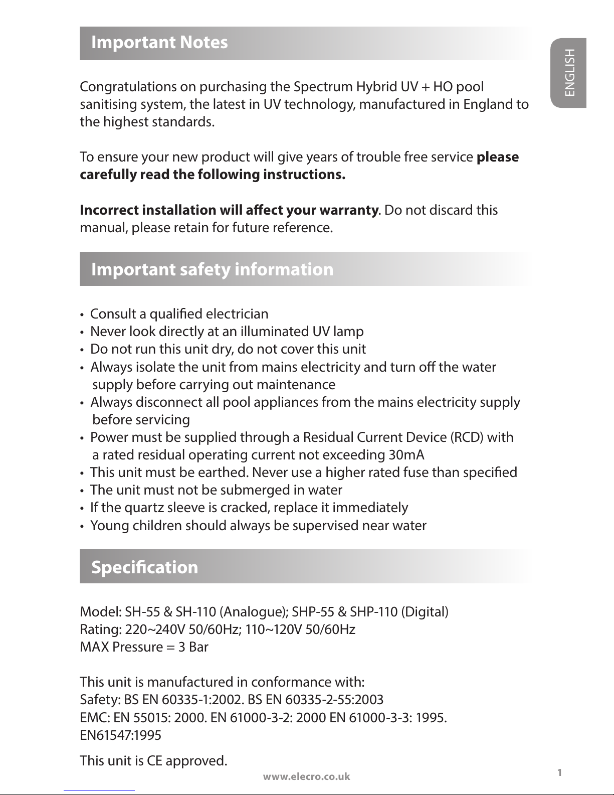
Product Overview
The Spectrum Hybrid is available in 55W single tube and 110W double
tube formats, supplied complete with ow switch and either an analogue
lamp life indicator and reset switch, or digital lamp life countdown with
intelligent dosing pump.
Fig 1.
FLOWTUBE COVER
CONTROL BALLAST
ASSEMBLY
BULB RETAINING
CLIP
BULB CAP
LOCKING NUT
‘O’ RING
UV BULB
QUARTZ GLASS
SLEEVE
REAR WALL
BRACKET
FRONT WALL
BRACKET
BRACKET FIXING
SCREWS
ELECTRONIC
CONTROLLER ASSEMBLY
MANIFOLD
ASSEMBLY
55W Single Tube Unit
Note: Digital Model Shown
2
www.elecro.co.uk
ENGLISH
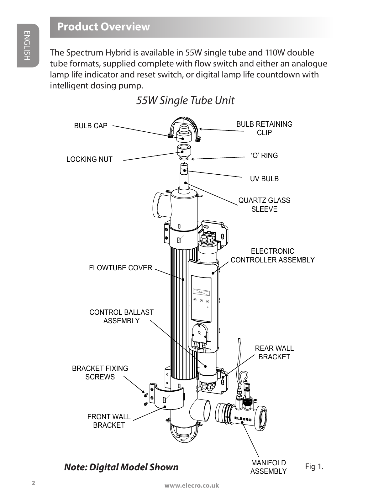
FLOWTUBE COVER
UV LAMP RETAINING
CLIP
LOCKING NUT
‘O’ RING
UV LAMP
QUARTZ GLASS
SLEEVE
BRACKET
ELECTRONIC
CONTROLLER ASSEMBLY
UV LAMP CAP
CONTROL BALLAST
ASSEMBLY
MANIFOLD
ASSEMBLY
Fig 2.
110W Double Tube Unit
3
Note: Digital Model Shown
www.elecro.co.uk
1
ENGLISH
Positioning the Unit
CAUTION: To prevent this unit falling into water, do not install above
or alongside your pool.
The Spectrum Hybrid unit is weatherproof but not waterproof; it must be
installed in a dry weatherproof enclosure. The unit must be mounted on a
at vertical surface horizontally or vertically. It must not be submerged in
water or placed in a position where water may collect around the unit.
To prevent the unit inadvertently being dropped into the pool, the unit
must be installed at least 3.5 metres from the edge of the pool.
The unit must always be plumbed into the water system after the lter as
shown in g 3. to prevent dirt and debris being pumped into the unit.
www.elecro.co.uk
FILTER
PUMP
ELECRO HEATER
POOL
NON RETURN
VALVE
UV SYSTEM
Fig 3.
POOL
ELECRO
SPECTRUM HYBRID
4
ENGLISH
55W

5
www.elecro.co.uk
ENGLISH
www.elecro.co.uk
FILTER
PUMP
ELECRO HEATER
POOL
NON RETURN
VALVE
UV SYSTEM
SPECTRUM
HYBRID
110W
Fig 4.
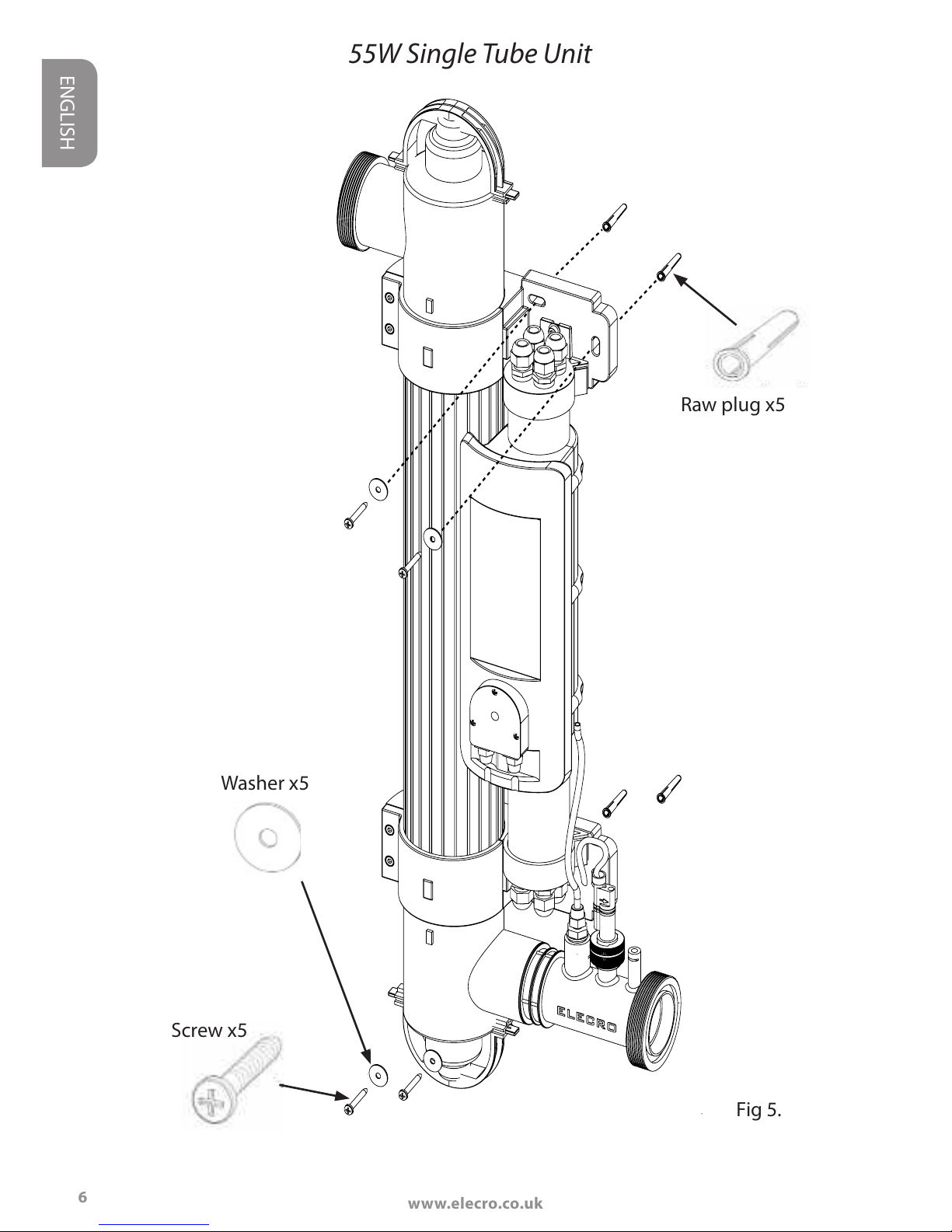
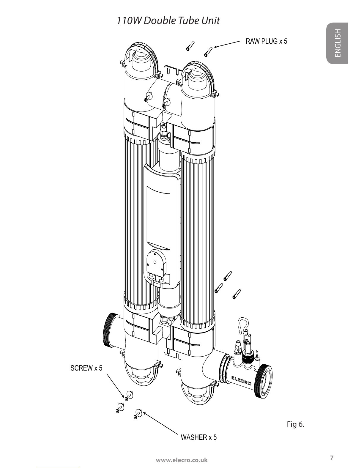
Mounting the UV Unit
The unit may be mounted on a wall or other suitable vertical surface that
is structurally strong enough (for example: when full of water the unit is
too heavy to mount onto a conventional wooden fence panel). The unit is
supplied with a xing kit. The unit can be mounted vertically as shown in
the next pages in g 5. and 6. or horizontally as shown in g 7.
NOTE!
When mounting the UV it is essential to leave a clearance space of at least 1m
from one side of the unit to allow access to replace the lamp(s) and/or quartz
sleeve(s) when required. Both the lamps and the quartz sleeve can be replaced
from either end of the unit; if installing vertically the 1m clearance space must
be above or below the unit, if installing horizontally the 1m clearance space
must be to the left or right of the unit.
www.elecro.co.uk
1
ENGLISH
WASHER x 4
RAW PLUG x 4
SCREW x 4
Washer x5
Screw x5
Raw plug x5
Fig 5.
6
55W Single Tube Unit
2
www.elecro.co.uk
ENGLISH
RAW PLUG x 5
WASHER x 5
SCREW x 5
Fig 6.
7
110W Double Tube Unit

www.elecro.co.uk
1
ENGLISH
www.elecro.co.uk
Fig 7.
ENGLISHENGLISH
Vertical
mounting
110W Double Tube Unit
Horizontal mounting
55W Single Tube Unit
Vertical
mounting
Horizontal mounting
8
Water must enter low
and exit high
Water must enter low
and exit high
Factory Default
Optional reverse ow
explained on page 10
Factory Default
Optional reverse ow
explained on page 10
Mounting Continued

2
www.elecro.co.uk
ENGLISH
Connection to the water supply
The unit is supplied with unions to allow connection to 2" or 63-mm rigid
pipe. Reducers are also supplied to allow connection to 50-mm or 1½" rigid
pipe - see g. 8.
For connection to 63mm or 2" diameter pipe
Insert 63-mm
diameter pipe up
to this stop
Insert 2" diameter
pipe up to this
stop
ADHESIVE
ABS
PVC ×
Insert 50-mm
diameter pipe up
to this stop
Insert 1½"
diameter pipe up
to this stop
Solvent weld your
pipe to the correct
stop
2
Solvent weld the
supplied reducer
into the union
1
9
NOTE!
ADHESIVE
ABS
PVC ×
NOTE!
Fig 8.
For connection to 50-mm or 1½" diameter pipe

www.elecro.co.uk
Flow Requirements
Minimum ow rate:
55W (single tube) and 110W (double tube) = 4m/hour
(4,000 litres per hour)
Maximum ow rate:
55W (single tube) = 12m/hour (12,000 litres per hour)
110W (double tube) = 24m/hour (24,000 litres per hour)
Your Spectrum Hybrid is factory set to accept input water ow entering on
the left and exiting on the right, this can be reversed by rotating the ow
switch 180 degrees (i.e ½ turn - see g. 8)
WARNING! The ow switch paddle can be damaged when reversing the ow
direction if it is lifted by more than 5mm from its housing and turned with
force. If the ow switch has been rotated it is important to ensure that it is
nally locked in the correct orientation perpendicular (at right angles) to the
ow of water.
Electrical connection
The unit must be installed in accordance with the country / regional
requirements and regulations. Always disconnect all pool appliances from
the mains electricity supply before servicing. In any event the work must
ENGLISH
10
Flow
Optional
reverse ow
Factory set
ow
Fig 8.
To reverse ow: Loosen retaining
nut (A) and rotate ow switch by
180 degrees as shown (B). Always
ensure the arrow marked on the
plastic ow switch body is in the
same direction as the water ow
B
A

2
www.elecro.co.uk
ENGLISH
11
be carried out by a qualied electrician, who will provide a certicate of
conformity upon completion of the work.
The power supply must be tted with a RCD with a rated residual
operating current not exceeding 30mA. This unit must be installed inside a
dry, weatherproof enclosure.
The unit is tted with 5 metres of power cable. To prevent the unit
inadvertently being dropped into the pool it must be securely positioned
at least 3.5 metres from the edge of the pool.
Lamp Life Indicator Model
(Analogue)
Under normal conditions the UV lamp(s) inside the unit have a usable life
of 9,000 hours. The unit is tted with a ‘Lamp Life Indicator’ LED in order to
remind you to change the lamp(s) after this set period of time.
At initial ‘Power On’ of the Spectrum Hybrid the LED indicator will light in
Red colour for one second to indicate that the time setting is 9,000 hours,
and immediately change colour to Green to indicate that the timer has
started.
When the timer reaches <500 hours the LED indicator will change colour
from Green to Amber to indicate that the UV lamp(s) is getting near to
its end of life; when the timer reaches zero the LED indicator will change
colour from Amber to Red, ashing slowly to signal that the UV lamp(s)
should be changed.
After changing the UV lamp(s) the timer is reset by pressing and holding
the reset button until the LED indicator goes ‘O’ and then comes back
‘On.’ When the reset button is released the LED indicator will come back
‘On’ (Red colour for one second followed by Green colour), this indicates
that the timer has restarted and is reset to count down the subsequent
9,000 hours.

www.elecro.co.uk
ENGLISH
12
Fig 9.
LAMP LIFE INDICATOR
RESET SWITCH

13
www.elecro.co.uk
ENGLISH
How to connect the suction tube to the dosing pump:
This is how the completed
assembly will look
STEP ONE
Components required:
Tubing
Foot Valve
Strainer
STEP TWO
Unscrew securing cap
anti-clockwise
Lamp Life Indicator + Intelligent
Dosing Pump (Digital)

www.elecro.co.uk
ENGLISH
A
B
1
2
3
STEP THREE
Thread tube through
the securing cap (1) and
component (2), then
push the pipe onto
component (3)
STEP FOUR
Once all components are
looped through the tubing
tighten securing cap
STEP FIVE
Lastly unscrew the retaining
gland and insert tube over
the connection point.
Tighten the retaining gland
Place the Foot Valve
Strainer into the
chemical container
Retaining
gland
Connection
point
Fig 10.
14

15
www.elecro.co.uk
ENGLISH
The factory default setting for the language is English.
To change to another language, press the / buttons until the de-
sired language appears, press OK to select and save.
- Language +
English OK ?
Fig 12.
Fig 11.
DIGITAL DISPLAY
BUTTONS
LED INDICATOR

www.elecro.co.uk
16
ENGLISH
To select a mode press the / buttons until the desired mode is
displayed then press the OK button to select that mode.
Operation:
When the unit is powered on the UV lamp is switched on, the UV lamp will
switch o under the following conditions ie:
• Dosing pump ‘On’ (and for 30 minutes after the dosing pump has
completed dosing)
• No or low water ow (the UV lamp(s) cannot be switched on unless
the unit is receiving sucient ow) See page 10 for ow requirements.
UV Lamp Life:
Adjust Dose
The digital controller has three modes ie:
• UV LAMP LIFE
• DOSAGE
• TIMER
Whenever the UV lamp is ‘On’ a timer
counts down from 9,000 hours and
the remaining UV lamp life is dis-
played.
From 9,000 hours to 500 hours the
LED in the control panel will light in
green. When 499 hours is reached
the LED colour will change to amber,
when 0 hours are reached the LED
light will change to red indicating
that the lamp(s) must be changed.
UV Life 460 Hrs
Dose 40m/d
LED Indicator
Fig 13.
Fig 14.

17
www.elecro.co.uk
ENGLISH
Set Dosage Requirements:
Please note: Dosage amounts are set in ml/day (millilitres per day)
Use the below reference table as a guide.
NOTE: The above table is based on dosing Hydrogen Peroxide (HO) with
a 32% concentration and a water temperature of 28C The digital control
ler will automatically sense the temperature of your water and adjust the
required dose accordingly
To calculate your pool volume see page 23-25 at the rear of this manual.
To set or adjust the dosage requirement:
Press the / buttons to scroll through the options until ‘ADJUST
DOSE’ mode is displayed and press the O.K. button to select.
When the UV lamp(s) are replaced
the lamp life timer must be reset
to 9,000 hours. In the UV lamp life
mode select ‘Reset UV Lamp’ by
pressing and releasing the O.K. but-
ton, then immediately press and
hold the O.K. button until the dis-
play shows ‘SAVED’ then release the
O.K. button, the display will then
show ‘UV Life 9,000 Hrs’ Please note
power failure does not aect this
lamp life countdown.
Reset UV Lamp
To 9000 Hours
Volume of
swimming pool
(m
Dosing amount
(ml/day)
35 200
50 320
60 420
80 620
90 700
100 800
130 1040

1
ENGLISH
www.elecro.co.uk
Adjust the dosage in 10ml steps using the / buttons, when the
required dosage is displayed press the O.K. button and the display will im-
mediately show ‘SAVED’ indicating that the new value has been stored in
the memory.
Set Timer:
After setting the required dosage it is necessary to set the start time which
is adjustable from 2 minutes to 23 hours 59 minutes in 1 minute steps
(please note it will always start at that time every 24 hours)
Press the O.K. Button to conrm the start time.
ENGLISH
Adjust Dose
Adjust Dose
40ml
Adjust Dose
SAVED
Start Dose in
1Hr 5Mins
Fig 15.
Fig 16.
Fig 17.
18

19
www.elecro.co.uk
ENGLISH
ENGLISH
EXAMPLE: Start time is set to 1 hour 5 minutes when the actual time is
10:10am therefore dosing will start at 11:15am on subsequent days.
PLEASE NOTE that the time selected for dosing must be at a time when
the main circulation pump is running.
In the event of a power failure (and at every power on) the 24 hour timer
will default to 2 minutes, when power is restored the start time will there-
fore almost certainly be incorrect and will need to be reset by the user. The
unit will not dose at the correct time until the timer is reset, although the
UV Lamp(s) will function as normal.
Intelligent Dosing Pump Routine Maintenance
We recommend that the dosing tube is changed every 12 months in order
to prevent any wear and tear and keep performance to an optimum. The
following steps will guide you how to replace the dosing tube:
STEP ONE
Unscrew the two screws securing the plastic cover and remove. Rotate the
grey connection caps to release the tubing.
STEP TWO
Remove the connection point on the
left hand side, and then carefully
manually rotate the cam clockwise to
allow removal of the dosing tube.

www.elecro.co.uk
ENGLISH
STEP THREE
Cut the two black securing ties
at either end of the pipe. This will
then release the tube, which can
be discarded.
STEP FOUR
Take the replacement tube and re-attach connection points. Loop secur-
ing ties in place in order to seal to the connection points. Once securely in
place cut the excess tie and dispose of.
STEP FIVE
Place dosing tube into position on
the left-hand side. Carefully rotate
the cam clockwise, whilst feeding
the pipe back into place.
STEP SIX
Replace the suction and output
tubes into connection caps, and
rotate to secure tubing back into
place. Replace clear cover and
screw into position.
20

21
www.elecro.co.uk
ENGLISH
Frost Protection
It is essential that the unit is protected from frost during the winter
months, or disconnected from the water and electricity supply and stored
inside a dry weather proof enclosure.
Lamp Replacement & Quartz Glass
Cleaning (all models)
Isolate from the electrical and water supplies before carrying out
any maintenance.
Lamp Holder restraint: A plastic Lamp holder restraint is tted at either
end of each lamp chamber to prevent the lamp holders being accidentally
removed while the unit is connected to the mains.
Each restraint is held in place with a self tapping screw. To carry out any
routine maintenance these restraints must be removed, it is essential to
re-attach them once the maintenance work has been completed. In time
it may be necessary to replace the existing no. 6 size screw with a slightly
larger size 8 screw.
To remove the lamp, carefully remove the blue lamp holder shroud, then
pull the white plastic electrical end caps from the lamp end. Gently slide
the lamp out ensuing that no pressure is applied to the glass quartz sleeve.
Next, unscrew the two blue compression ttings located at either end of
the main body and slide o the ’O’ rings. Then slide out the quartz glass
sleeve. Clean the sleeve and polish with a soft cloth or paper towel.
If you live in a hard water area there maybe some limescale on the quartz
sleeve. This can be easily removed by soaking the sleeve in a proprietary
kettle descaling solution (follow the manufacturer’s instructions). Failure to
remove the limescale will limit the eectiveness of the UV lamp(s).
Assembly process: Slide the clean, dry quartz glass sleeve into the unit.
Ensure that you locate the ’O’ rings carefully on the ends of the quartz.
Failure to do so will result in leaks when the water is turned on. If you are
carrying out the annual lamp change, use new ’O’ rings. When you re-
assemble the unit, ensure that the female threads on the compression
ttings and the male threads on the main body are clean.

www.elecro.co.uk
22
ENGLISH
Wipe a little silicone grease or Vaseline (not silicone sealant) onto these
threads. As these threads are only serviced periodically, this lubrication will
help to prevent them binding together. Then ret and rmly hand tighten
the compression ttings. Ret or replace the UV lamp(s) with a new one.
Relocate the lamp holders and blue lamp holder shrouds ensuring that
you match the correctly numbered lamp holder.
Note: Pinch the blue lamp holder shroud as you reassemble the unit to
release any trapped air. Failure to release the trapped air may cause the
lamp holder to disconnect from the lamp end. Reconnect and turn on the
water supply to check for leaks before reconnecting the electric supply.
Important: The plastic body and blue compression ttings have been
manufactured from polymers that have been specically stabilised to
protect them from the eects of the UVC emitted from the UV lamps.
Despite this UV protection they will be eroded by a combination of the
UVC and water ow. As a matter of course they should be inspected
whenever a lamp change is carried out, to ensure they are not showing
excessive wear and tear. Replacement parts are available.

23
www.elecro.co.uk
ENGLISH
RoHS Compliance Statement
Elecro Engineering Limited certify that our UV Pool sanitiser range
complies in accordance with RoHS Directive 2011/65/EU on the restriction
of hazardous substances.
Waste of Electrical / Electronic Equipment
This product complies with EU directive 2012/19/EU
Do Not dispose of this product as unsorted municipal waste.
This symbol on the product or on its packaging indicates that this product
should not be treated as household waste. Instead it should be handed
over to the applicable collection point for the recycling of electrical and
electronic equipment.
By ensuring this product is disposed of correctly you will
help prevent potential negative consequences for the
environment and human health, which could otherwise be
caused by inappropriate waste handling of this product.
The recycling of materials will help to conserve natural
resources.
For more information please contact your local Civic oce,
your household waste disposal service or the retailer
where you purchased the product.
Guarantee
Your Spectrum Hybrid pool sanitiser is guaranteed for 3 years from the
date of purchase against faulty workmanship and materials.
The manufacturer will replace or repair, at it’s discretion, any faulty units or
components returned to the company for inspection.
Proof of purchase may be required. The manufacturer will not be liable in
cases of incorrect installation of the product, inappropriate use, or neglect.
This guarantee does not include serviceable parts, ie: lamps, quartz
sleeves, dosing tube and o-rings, etc.

Calculating Pool Volumes
The following pages will show you how to calculate the volume of your pool.
NB For pools with dierent depths:
D1 + D2
= Average Depth
2
If your pool has a sloping bottom, then take the deepest measurement (D2) and the shallowest
(D1). If there are dierent levels, then you need to do several calculations of area for each depth
and add them up at the end.
Rectangle & Square Pools
Volume = Length (L) x Width (W) x
Depth (D)
Average Depth
Circular
Volume = π (3.142) x Radius x
Depth (D)
Average Depth
Radius = Diameter divided by 2
Radius
24
ENGLISH
www.elecro.co.uk

25
Ellipses
Volume = π (3.142) x A x B x
Depth (D)
Average Depth
Irregular Shapes
For irregular shapes, calculating the area is less accurate. You will need to
draw up the pool accurately to scale on graph paper using a square on the
paper to represent a metre (or foot) square of pool. When you have nished,
count the squares.
For partial squares, count anything over half as one and ignore any under
a half. When you have the area (A) multiply by depth (D) for the Volume in
cubic metres. If you have several depths, break up your area calculation for
each depth.
A
B
ENGLISH
www.elecro.co.uk

Useful Conversions
Cubic Metres to Litres = Multiply by 1000
Cubic Feet to Cubic Metres = Multiply by 0.0283168
UK Gallons to Litres = Multiply by 4.54609
Litres to Cubic Metres = Multiply by 0.001
Cubic Metres to UK Gallons = Multiply by 219.969
ENGLISH
26
ENGLISH
www.elecro.co.uk

11 Gunnels Wood Park | Stevenage | Hertfordshire | SG1 2BH | United Kingdom
t: +44 (0) 1438 749 474 | f: +44 (0) 1438 361 329 | e: sales@elecro.co.uk
www.elecro.co.uk
© Copyright 2016 Z-INS-SH
 Loading...