

Page 1
Pool-Smart
Installation Instructions
& Operating Manual
ARNING
W
Incorrect Installation Will Affect Your Warranty
Do Not Discard, Keep For Future Reference
HIS CONTROL DEVICE MUST BE INSTALLED
: T
BY A QUALIFIED ELECTRICIAN
Page 2

UICK SET
Q
Screw mount the Pool-Smart to a wall in a dry weather proof location, ensuring that it is sited no
more than 3 metres from the swimming pool filtration pipe work and upstream i.e. before the
heating appliance.
Solvent cement the PVC T-Piece into the pipe work ensuring the direction arrow (moulded into
the T-Piece) is pointing in the direction of flow.
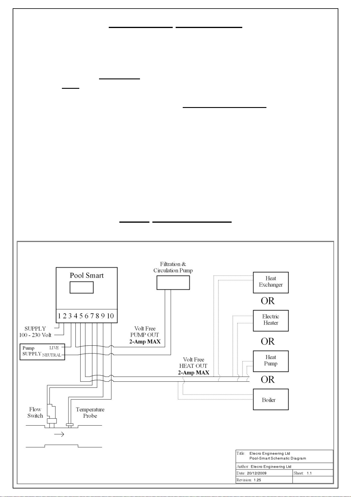
Electrical connection: To access the internal terminal connection block
Remove the 4 cover screws in the lower section of the controller housing & connect as follows:
Terminal 1 and 2 Power supply 100-230 volt ac mains
Terminal 3 and 4 connect to the filtration pump / contactor controlling the filtration pump (volt
free switched output 2-Amp MAX)
Terminal 5 and 6 connect to the heating appliance (volt free switched output)
Terminal 7 and 8 connect to the flow switch in the T-Piece
Terminal 9 and 10 connect to the temperature sensor in the T-Piece
For programming and functionality refer to the digital controller key section
-UP G
UIDE
ULL INSTALLATION INSTRUCTIONS
F
OSITIONING
P
The Pool-Smart should be installed in a dry weather proof location that will allow access to the
control buttons. Consideration must be given to the positioning of the T-Piece to ensure both the
controller and T-Piece are no more than 3 metres apart.
The T-Piece incorporates a flow switch and temperature sensor and must be sited up stream,
i.e. before, the pool heating appliance.
W
ALL
The rear face of the Pool-Smart has an upper key hole screw hook, located at the rear of the enclosure, and 2 lower screw holes which are accessed after removing the 4 screws retaining the
lower access cover.
T-P
IECE INSTALLATION
M
OUNTING
The T-Piece should be cut into the swimming pool filtration pipe work up stream (i.e. before) the
heating appliance using a suitable PVC cement. The T-Piece has slip fit female 63-mm and is
supplied with 50-mm reducers for metric countries or 1½" reducers for imperial countries.
Note:- correct orientation of the T-Piece is essential in order to facilitate the correct operation of
the flow switch, and temperature detecting probe i.e. the arrow moulded into the T-Piece must
point in the direction of flow.
Page 3
E
LECTRICAL CONNECTION
Terminals 1 and 2: Connect to a permanent power supply of 100-230 volts AC (Mains) fused at
3-Amp.
Terminals 3 and 4: Connect to the filtration pump; i.e. route the live from the supply to the pump
through position 3 and 4. WARNING
iary contactor must be installed to switch the pump.
Terminals 5 and 6: Connect to the heating device - under no circumstances
and 6 be connected to a load greater than 2-Amp.
Recommended connection method.
Using a suitable 2 core wire connect the 2 cores from one end of the wire to terminals 5 and 6.
Then connect the free end of the wire to the heating appliance by disconnecting one of the connections from the thermostat of the heating device, and re connecting (join) it to one of the cores
of the 2 core wire. The remaining free core of the 2 core wire should then be connected to the terminal on the heating device’s thermostat.
Terminals 7 and 8 , connect to the flow switch installed in the T-Piece.
Terminals 9 and 10 connect to the temperature-detecting probe installed in the T-Piece.
: If a circulation pump draws more than 2-Amp an auxil-
should terminals 5
LOW REQUIREMENTS
F
The flow switch fitted in the T-Piece requires a minimum flow rate of 4,000 Litres-per-hour.
Page 4

P
OOL-SMART DIGITAL CONTROLLER
The Elecro Pool-Smart has been pre-programmed with all the necessary parameters to ensure reliable service & operation. Below is a key explaining the controllers buttons & LED signals.
K
EY
Press and hold for 2 seconds to power the control on / off.
Press to increase required pool temperature.
Press to decrease required pool temperature.
Press and release to activate / deactivate ‘Priority of Heating’
The actual pool temperature is displayed in the red upper display. The lower green display
‘required temperature’ can be selected by the user. This is the temperature you would like your
pool water to be maintained at.
Priority of Heating is a function that ensures the pool water is constantly maintained at the required temperature. When Priority heati ng is activated the Priority Heating Icon on the bottom
right of the display will illuminate. The control will now monitor the pool temperature, and start
both the pool circulation pump and heating process when necessary.
Page 5

C
IRCULATION PUMP INTERLOCK
The Pool-Smart can also control the circulation pump by switching the circulation pump on & off
whenever the Pool-Smart is in Priority of Heating mode. To connect the pump to the Pool-Smart
you will need to connect to terminals numbered 3 & 4 within the Pool-Smart.
NOTE: Any pump that draws more than 2-Amp Must
An example of how to connect via an external contactor is given below:
be connected via an external contactor.
Pool-Smart
Terminals 3 & 4
IME SWITCHING DELAY
T
To prevent overheating of the switch components within your heating device caused by frequent
on and off switching (cycling), the Pool-Smart digital controller has been pre-programmed with a
time delay function. This prevents rapid fluctuations in temperature or flow volume from switching the heating device on and off more than once in a two minute period.
The time delay mode is indicated by the flashing LED next to the word HEAT on the digital display. (See diagram on following page).
IFFERENTIAL
D
When the pool water has reached the required temperature the Pool-Smart will switch off the
heating device and it will not allow the heating device to switch back on until the water temperature has dropped 0.6˚C. This value is known as the differential and is also in place to prevent
overheating of the switch components caused by cycling.
Page 6

T
ROUBLE SHOOTING
Heating device will not switch to HEATER ON mode
In most cases this will be the result of one of the following not being met.
Possible Cause 1.) The required temperature has been achieved.
To confirm that the Pool-Smart is requesting the heating device to heat check that the window
next to the word HEAT is illuminated (see diagram below). If illuminated go to step 2, if not illuminated increase the required temperature to a value higher than the current water temperature.
Confirm whether the heating device now switches on
HEAT = If Continuously Illuminated
REQUIRED
TEMP
PRIORITY OF HEATING
Possible Cause 2.) Insufficient Flow.
The display will display a NoFL alarm message in the upper (red) display window when the
Pool-Smart has detected that the flow rate has dropped below 4,000-litres per hour or has stopped
completely.
Indicates that the water temperature has fallen below
the required temperature.
HEAT = If Flashing
Indicates that the heater is in timed delay mode (see
previous page).
Useful advice: To reduce running costs and speed up the heating process ;
Insulate
the pool wherever possible. A floating solar cover is an essential min imu m to retain
heat.
W
ASTE
OF E
LECTRICAL
LECTRONIC EQUIPMENT
/ E
This product complies with EU directive 2002/96/EC
Do Not dispose of this product as unsorted mun i cipal waste.
This symbol on the product or on it’s packaging indicates that this product should not be treated
as household waste. Instead it should be handed over to the applicable collection point for the recycling of electrical and electronic equipment.
By ensuring this product is disposed of correctly you will help prevent potential negative consequences for the environment and human health, which could otherwise be caused by inappropriate waste handling of this product. The recycling of materials will help to conserve natural resources. For more information please contact your local Civic office, your household waste disposal service or the retailer where you purchased the product.
ROHS C
OMPLIANCE STATEMENT
Elecro Engineering Limited certify that our Electric Swimming Pool Heater Range complies in
accordance with RoHS Directive 2002/95/EC on the restriction of hazardous substances.
Page 7

GUARANTEE
Your Pool-Smart is guaranteed for 1 year from the date of purchase against faulty
workmanship and materials.
The manufacturer will replace or repair, at it’s discretion, any faulty units or compo-
nents returned to the company for inspection. Proof of purchase may be required.
The manufacturer will not be liable in cases of incorrect installation of the controller,
or inappropriate use, or neglect of the controller.
CE Declaration Of Conformity
The manufacturer declares that the herewith products or ranges
POOL SMART DIGITAL CONTROLLER RANGE
Are in conformity with the provisions:
of the ELECTROMAGNETIC COMPATIBILITY directive 89/336/EEC, as
amended 93/068/EEC. Controlled by AEMC Measures laboratory—technical report
no P96045T
The harmonised standards have been applied: EN 55014—EN 55104
EN 55011
EN 55022
CEI 801-4
CEI 801-2
CEI 801-3
of the LOW VOLTAGE directive 73/23/EEC.
The harmonised standards have been applied
EN 60335-2-35
Elecro Engineering Limited
Unit 11 Gunnels Wood Park
Stevenage
Hertfordshire
SG1 2BH
UK
Tel: +44 (0) 1438 749 474 Fax : +44 (0) 1438 361 329
Website: www.elecro.co.uk Email: info@elecro.co.uk
© Copyright 2010
 Loading...