

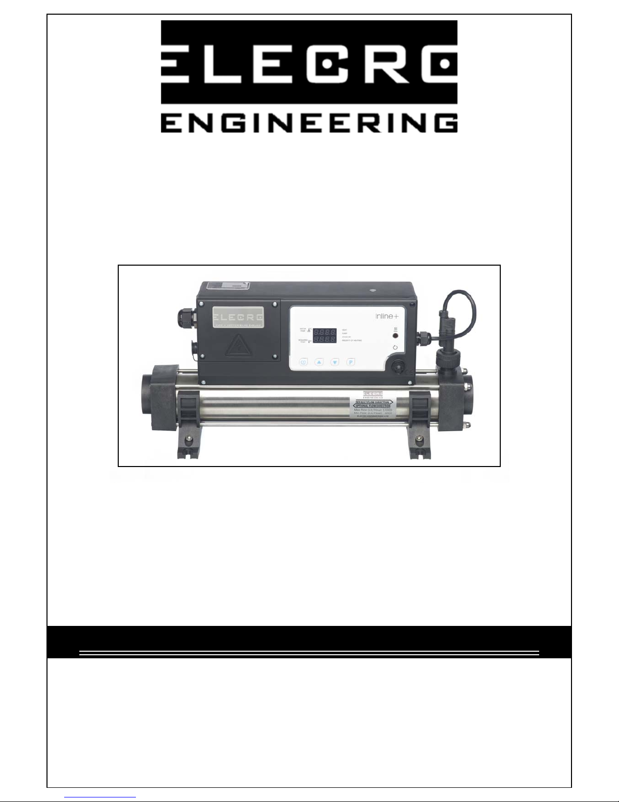
Elecro Engineering In-Line + Swimming Pool Heater, In-Line+ Installation Instructions & Operating Manual
PLEASE READ CAREFULLY BEFORE INSTALLING
Do Not Discard, Keep For Future Reference
Incorrect Installation Will Affect Your Warranty
In-Line + Swimming
Pool Heater
Installation Instructions
& Operating Manual

POSITIONING
Your heater must be screw fixed to a firm base or wall. The heater MUST be horizontal and
upright i.e. with the control enclosure located above the flow tube (see diagram below). Under no
circumstances should the heater be operated in any other orientation.
The heater should be installed at a low point in the filtration system. It should be positioned after
(i.e. downstream) of the filter but before (i.e. upstream) of any dosing or other water treatment
plant.
NOTE If the
flow direction
is reversed
(explained
later in this
booklet) the
heater MUST
remain sited
after the filter.
Only clean filtered water
should ente r the heater.
It is essential that the pipe work connecting to and from the heater has a minimum bore (internal
diameter) of 1¼’’ (32-mm).
To assist correct air purging and to ensure the heater remains completely full of water during
operation, the return pipe which carries the water back to the pool must incorporate a safety loop
or kick up in the pipe, installed as close as possible to the heater (see diagram on following
page).
Note: When coupling to flexible pipe a safety loop can simply be created by routing the pipe up
and over an obstacle. Remember to use pipe clips to securely fasten all hose connections.
PIPE WORK

WEATHER PROTECTION
The heater should be installed within a dry weatherproof enclosure.
CAUTION
If the heater is not used during winter months it must be drained to prevent frost damage.
Upon completion of the installation, run the water-circulating pump to purge the system & heater
of air (i.e. remove any trapped air in the system & heater).
The heater must be installed in accordance with the country / regional requirements &
regulations. In any event the work must be carried out by a qualified electrician, who will
provide a certificate of conformity upon completion of the work.
The power supply must be fitted with a RCD. If required your electrician may replace the
supplied cable entry gland with a larger one to secure the cable powering the heater, this will not
affect your warranty if carried out by a qualified electrician.
Cable section: should be calculated at 5-amp / mm² for distances up to 20 metres (these sections
are indicative and should be checked and adapted if necessary for cable lengths over 20 metres).
POWER REQUIREMENTS
Power Output Volt (V) Amp
2-kW 230 9
3-kW 230 13
4.5-kW 230 20
6-kW 230 27
9-kW 230 40
12-kW 230 53
15-kW 230 66
18-kW 230 79
ELECTRICAL CONNECTION
3 Phase
Power
Output
400V
St ar /
230V
Delta
Amp
6-kW 400V / 230V 9 / 15
9-kW 400V / 230V 13 / 23
12-kW 400V / 230V 18 / 31
15-kW 400V / 230V 22 / 38
18-kW 400V / 230V 26 / 46
24-kW 400V 35
 Loading...