

Page 1

www.elecro.co.uk
1
FLOW-LINE Pool Heater
Installation & Operating Manual
Page 2

www.elecro.co.uk
1
www.elecro.co.uk
ENGLISH
Important Notes!
Thank you for purchasing the FLOW-LINE direct electric swimming pool
heater manufactured in England to the highest standards.
To ensure your new heater will give years of trouble free service please
carefully read the following instructions. Incorrect installation will
a ect your warranty.
Do not discard this manual, please retain for future reference.
Product Overview
Fig 1.
Termperature set
point dial
RH End tting
RH End tting
Foot / Carrier
Foot / Carrier
Flow tube
Thermal safety
Cut-out
re-set switch
Top access cover
Flow switch
Page 3
www.elecro.co.uk
2
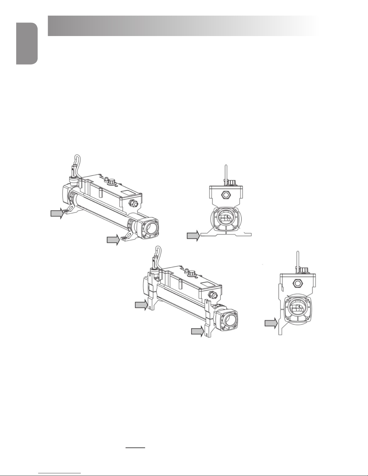
Positioning
Your heater should be horizontally or vertically sited allowing su cient
space for pipe connections and wiring, it should be screw xed securely to
a rm base or wall.
NOTE: See gure 2 for details of the foot arrangement when securing
to the wall or oor.
The heater should be installed at a low point in the ltration system.
It should be positioned downstream (after) of the lter and upstream
(before) of any dosing or other water treatment plant. (see g.3)
NOTE : If the ow direction is reversed (explained later in this
booklet) the heater must remain sited after the lter.
Factory set oor
mount ‘Foot position’
To reset for wall
mount option,
undo the bolts and
re-assemble in the
vertical position as
shown.
Floor mount ‘Foot position’
Wall mount ‘Foot position’
Fig 2.
ENGLISH
Page 4

www.elecro.co.uk
3
www.elecro.co.uk
ENGLISH
Flow switch
at top
For vertical wall
mounting water
must always enter
at the bottom
Fig 3.
Fig 4.
Page 5

www.elecro.co.uk
4
Pipe Work
It is essential that the pipe work connecting to and from the heater
has a minimum bore (internal diameter) of 1¼” (32mm). To assist correct air
purging and to ensure the heater remains completely full of water during
operation, the return pipe which carries the water back to the pool must
incorporate a safety loop or ‘kick-up’ in the pipe as close as possible to the
heater (see g 4)
NOTE: When coupling to a exible pipe a safety loop can simply be
created by routing the pipe up and over an obstacle. Remember to
use pipe clips to securely fasten all hose connections.
Weather Protection
The heater must be installed within a dry weather proof enclosure.
Caution! If the heater is not used during winter months it must be drained to
prevent frost damage.
Electrical Connection
The heater must be installed in accordance with the country / regional
requirements & regula-tions. In any event the work must be carried out
by a quali ed electrician who will provide a certi cate of conformity
upon completion of the work. The power supply must be tted with a
RCD.
Fig 5.
Remove Top Access Cover
to make the electrical
connections
(Quali ed electricians only)
ENGLISH
Page 6

www.elecro.co.uk
5
www.elecro.co.uk
Control Circuit
The Flow-line heater is supplied with all the necessary connections to
correctly wire the control circuit that then requires nal connection to
A1 / A2 of the external contactor(s) as per the wiring diagram at rear
of this book.
Contactors are not provided with your Flow-Line heater and are
essential! Supply and tting is the responsibility of the installation
technician. These must be sited in an external cabinet and wired in
accordance with local regulations.
Control Components Include:
Control Circuit Important Electrical Data:
Limited by the ow switch (reed switch)
Contact Rating - 90.0 W/VA
Switching Current MAX - 1.0 Amp
Switching Voltage MAX - 230V AC
ENGLISH
Qty Description
1 0˚C to 40˚C Control Thermostat
1 55˚C Thermal cut-out (manual re-set)
1
Flow Switch Pre-Set 1,000-litres / hour for 3 ~ 6 kW (220 UK
gallons/hour)
4,000-litres / hour for 9 ~ 18 kW (880 UK gallons/hour)
Power Requirements
Power
Output
Single
Phase
Voltage
Amp
3 - kW 230V 13
6 - kW 230V 27
9 - kW 230V 40
Power
Output
3 Phase
Voltage
Amp
6 - kW 400 / 230V 9 / 15
9 - kW 400 / 230V 13 / 23
12 - kW 400 / 230V 18 / 30
15 - kW 400 / 230V 22 / 38
18 - kW 400 / 230V 26 / 46
Page 7

ENGLISH
Flow Requirements
Your heater is factory set to accept input water ow entering on the left
and exiting on the right, this can be reversed by rotating the ow switch
180 degrees (ie:½ turn, see g 6)
WARNING! The ow switch paddle can be damaged when reversing the ow
direction if it is lifted by more than 5mm from its housing and turned with
force. If the ow switch has been rotated it is important to ensure that it is
nally locked in the correct orientation perpendicular (at right angles) to the
ow of water.
The ow rate of water into the heater must not exceed 17,000 litres per
hour (3,740 UK gallons/hour) A higher ow rate will require the installation
of a bypass to prevent damage to the heater elements. The heater will not
operate unless the following minimum ow rates are achieved ie:
1,000 litres / hour (220 UK gallons/hour) for 2 ~ 6-kW heaters and
4,000 litres / hour (880 UK gallons/hour) for 9 ~ 24-kW heaters.
Factory set ow
Optional reverse
o w
Flow
Fig 6.
To reverse ow: Loosen
cap and rotate Flow
switch by 180 degrees as
shown.
Always ensure the arrow
marked on the plastic ow
switch body is in the same
direction as the water ow
6
www.elecro.co.uk
Page 8

www.elecro.co.uk
ENGLISH
ENGLISH
7
Wiring Diagram
Page 9

ENGLISH
8
www.elecro.co.uk
Wiring Diagram
Page 10

www.elecro.co.uk
ENGLISH
ENGLISH
9
Wiring Diagram
Page 11

www.elecro.co.uk
10
RoHS Compliance Statement
Elecro Engineering Limited certify that our Electric Swimming Pool Heater
Range complies in accordance with RoHS Directive 2002/95/EC on the
restriction of hazardous substances.
Waste of Electrical / Electronic Equipment
This product complies with EU directive 2002/96/EC
Do Not dispose of this product as unsorted municipal waste.
This symbol on the product or on it’s packaging indicates that this product
should not be treated as household waste. Instead it should be handed
over to the applicable collection point for the recycling of electrical and
electronic equipment.
By ensuring this product is disposed of correctly you will
help prevent potential negative consequences for the
environment and human health, which could otherwise be
caused by inappropriate waste handling of this product.
The recycling of materials will help to conserve natural
resources.
For more information please contact your local Civic o ce,
your household waste disposal service or the retailer
where you purchased the product.
ENGLISH
Page 12

www.elecro.co.uk
11
www.elecro.co.uk
Guarantee
Your heater is guaranteed from the date of purchase against faulty
workmanship and materials ie: 2 years guarantee for incoloy heating
element products and 3 years guarantee for titanium heating element
products.
The manufacturer will replace or repair, at it’s discretion, any faulty units or
components returned to the company for inspection.
Proof of purchase may be required.
The manufacturer will not be liable in cases of incorrect installation of the
heater, inapropriate use or neglect of the heater.
CE Declaration Of Conformity
The manufacturer declares that the herewith products or ranges
ELECTRIC SWIMMING POOL HEATER RANGE
Are in conformity with the provisions:
of the ELECTROMAGNETIC COMPATIBILITY directive 89/336/EEC, as
amended 93/068/EEC. Controlled by AEMC Measures laboratory—
technical report no P96045T
The harmonised standards have been applied: EN 55014—EN 55104
EN 55011
EN 55022
CEI 801-4
CEI 801-2
CEI 801-3
of the LOW VOLTAGE directive 73/23/EEC.
The harmonised standards have been applied
EN 60335-2-35
Product Overview
ENGLISH
Page 13

11 Gunnels Wood Park | Stevenage | Hertfordshire | SG1 2BH | United Kingdom
t: +44 (0) 1438 749 474 | f: +44 (0) 1438 361 329 | e: info@elecro.co.uk
www.elecro.co.uk
© Copyright 2011
 Loading...