

Elecro Engineering Cygnet Aquatic Heater 1-kW, Cygnet Aquatic Heater 3-kW, Cygnet Aquatic Heater 4-kW, Cygnet Aquatic Heater 2-kW Installation & Operating Manual
Page 1

Cygnet Aquatic Heater
Installation & Operating Manual
Page 2

ENGLISH
Contents
Page
ENGLISH ........................................................................................................ 1 - 9
ESPAOL ....................................................................................................... 10 - 19
FRANÇAIS ..................................................................................................... 20 - 29
DEUTSCH ...................................................................................................... 30 - 39
www.elecro.co.uk
Page 3

Important Notes!
Thank you for purchasing the CYGNET Aquatic Heater manufactured in
England to the highest standards.
To ensure your new heater will give years of trouble free service please
carefully read the following instructions.
Incorrect installation will aect your warranty.
Do not discard this manual, please retain for future reference.
The appliance is not to be used by children. The appliance is not to be used
by persons with reduced physical, sensory or mental capabilities, or lack
of experience and knowledge, unless they have been given supervision or
instruction.
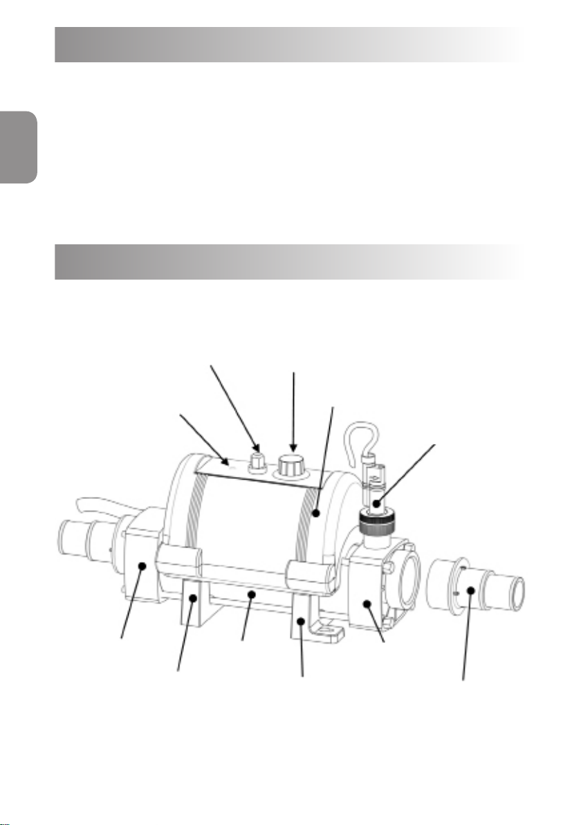
Product Overview
Thermal safety
Cut-out
re-set switch
Heater ‘ON’
Indicator (red)
Temperature
set
point dial
Top cover
Flow switch
ENGLISH
LH End tting
Foot /Carrier – A
Fig 1.
Flow tube
Foot / Carrier—B
www.elecro.co.uk
RH End Fitting
Hosetail Stepped
Connector
1¼” (32mm) or
1½” (38mm)
1
Page 4
ENGLISH
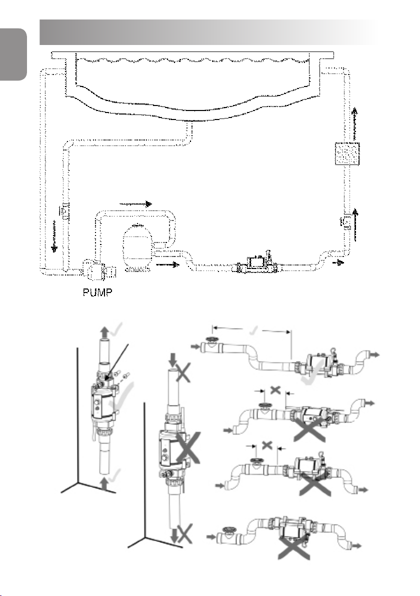
Positioning
POND
WATER
TREATMENT
VALVE
NON RETURN
YES
For vertical wall
mounting water
must always enter
at the bottom
2
PUMP
FILTER
Flow switch
at top
CYGNET AQUATIC HEATER
Fig 2.
NO
NO
NO
NO
Fig 3.
www.elecro.co.uk
Page 5

Positioning (continued)
Your heater should be horizontally or vertically sited allowing sucient
space for pipe connections and wiring, it should be screw xed securely to
a rm base or wall.
The heater should be installed at a low point in the ltration system.
It must be positioned downstream of (after) the lter and upstream of
(before) any dosing or other water treatment plant. (see Fig.2)
Pipe Work
It is essential that the pipe work connecting to and from the heater
has a minimum bore (internal diameter) of 1¼” (32mm).
To assist correct air purging and to ensure the heater remains completely
full of water during operation, the return pipe which carries the water back
to the pond must incorporate a safety loop or ‘kick-up’ in the pipe as close
as possible to the heater (see g 3).
NOTE: When coupling to a exible pipe a safety loop can simply be
created by routing the pipe up and over an obstacle. Remember to
use pipe clips to securely fasten all hose connections.
ENGLISH
Weather Protection
The heater must be installed within a dry weather proof enclosure.
CAUTION! If the heater is not used during winter months it must be drained to
prevent frost damage.
Electrical Connection
The heater has been supplied pre-wired with a power lead. Sizes 1-kW
to 3-kW also have a plug; 4-kW models must be installed by a qualied
electrician.
www.elecro.co.uk
3
Page 6
ENGLISH
requirements and regulations. In any event the work must be carried out
by a qualied electrician, who will provide a certicate of conformity upon
completion of the work.
It is essential that the power supply to the heater is protected by a
30mA RCD (Residual Current Device). If in doubt consult a qualied
Electrician.
Power Requirements
The heater must be installed in accordance with the country / regional
230V 1 PhasePower Output
1-kW
Load
5-Amp
2-kW 9-Amp
3-kW
4-kW*
13-Amp
18-Amp
*4-kW MUST BE HARDWIRED
BY A QUALIFIED ELECTRICIAN
Flow Requirements
The ow rate of water into the heater must not exceed 17,000 litres per
hour (17m/h / 3,740 UK gallons/hour) A higher ow rate will require the
installation of a bypass to prevent damage to the heater elements. The
heater will not operate with a ow rate below 1,000 litres / hour (1m/h or
220 UK gallons/hour)
Water Quality
The water quality must be within the following limits:
PH 6.8 - 8.0 TA (Total alkalinity) 80—140ppm (parts per million)
TDS (Total Dissolved Solids) / Calcium hardness 200 - 1,000ppm
The Cygnet Aquatic heaters are suitable for use with salt water ponds with
a salt concentration up to 8000ppm (8g/litre).
Water chemistry is complicated if in doubt seek expert advise.
4
www.elecro.co.uk
Page 7

Operating Instructions
Upon completion of the installation, run the water-circulating pump to
purge the system and heater of air (i.e. remove any trapped air in the
system and heater). TIP: You can encourage air out of the heater ow tube
by gently elevating the exit port of the heater when the pump is running.
The heater will only switch ‘On’ (red light indicator illuminated) when the
following criteria are met ie:
· Water circulating pump is ‘On’ delivering in excess of 1,000 litres /
hour (1m/h or 220 UK gallons/hour)
· Required temperature is set to a higher value than the water
temperature.
Useful advice: To reduce running costs and speed up the heating process,
insulate the pond wherever possible.
Quick Function Test
Observe the main electricity meter when the heater is on (ie: red light ‘On’)
and then observe it again when the red light is o. The test should show
that the meter is recording more electricity being used by the heater when
the red light is ‘On’.
ENGLISH
It is impossible for an electric heater to waste energy, if it is
drawing power then that power will be turned into heat that will be
transferred to the water.
Accurate Function Test
If a more accurate test is required to conrm that your heater is delivering
the specied heat output, two electricity meter readings will need to be
taken from the properties main electricity meter, with an exact one hour
interval (ie: take one meter reading and then a second reading exactly one
hour later) then by subtracting the rst reading from the second
reading the number of units (kilowatts / kW) consumed can be calculated.
www.elecro.co.uk
5
Page 8
ENGLISH
Note that your heater is also rated in kW hours. The pond pump and heater
will need to be running continuously during the test (ie: with the heater
red light ’On’) To avoid inaccurate results when performing this test, it is
important to refrain from using other high current consuming appliances
in the property (such as tumble dryer, showers, cookers etc).
A large aquatic pump of 1 horsepower will draw less than 1-kW in a one
hour period. The conclusion of the test should prove that for example
a 3-kW heater and a ½ horsepower pump will draw between 3.3-kW ~
3.5-kW in one hour. It is impossible for an electric heater to waste energy,
if it is drawing power then that power will be turned into heat that will be
transferred to the water.
Trouble Shooting
HEATER WILL NOT SWITCH ‘ON’
In most cases this will be the result of one of the following points not
being met.
Possible cause 1: The required temperature has been achieved.
To conrm: increase the set point value by turning the temperature set
point dial to a value greater than the current water temperature.
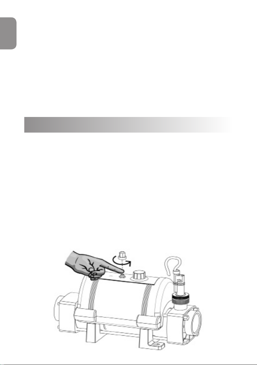
Possible cause 2: The ‘Thermal safety cut-out’ has tripped.
Remedy: Remove button cover and press red button to re-set (see g 4)
If a positive click is felt, the cause of the tripping must be investigated and
could be caused by a debris build-up or air pocket trapped inside the ow
tube of the heater.
6
www.elecro.co.uk
Fig 4.
Page 9

Possible cause 3: Insucient ow.
If using a cartridge lter: Conrm this by running the system with the
cartridge removed from your pump and lter unit, this will supply the
heater with the maximum ow rate your unit is capable of. If the heater
then switches ’On’ (ie: red light ’On’) a blocked cartridge can be conrmed
to be the cause. The cartridge should be cleaned or replaced.
If using a sand lter: Check the pressure indicator on your sand lter and
back wash if necessary.
Note: In some cases the ‘Thermal safety cut-out’ tripping and a low
ow rate can be linked ie: when a lter becomes choked air can be
drawn into the ltration system and become trapped inside the
heater, so causing the thermal cut-out to trip.
General Trouble Shooting
THE FLOW TUBE DOES NOT FEEL WARM
Due to the high eciency of your electric heater no warmth should be
detectable from the ow tube of the heater.
The most likely causes of the ow tube feeling warm are:-
ENGLISH
Possible cause 1: The heater has been positioned in direct sunlight.
Possible cause 2: An air pocket is trapped inside the heater particularly if the
ow tube feels warmer at the highest point (as air rises).
THE WATER ENTERING MY POND DOES NOT FEEL MUCH WARMER
The temperature gain of the water after it has passed through the heater
will be directly proportional to the volume of water being pumped in
relationship to the power output of the heater.
For example: A 6-kW heater, when connected to a 4,000 litre / hour
(4m/h) pump, will produce a lift in temperature of approximately 1.2°C
(almost undetectable to the human hand) however, as the water being
heated is re-circulated from a single body of water, the time required to
heat it remains unaected by the volume of ow. A popular misconception
is that slowing down the ow rate will speed up the heating process.
www.elecro.co.uk
7
Page 10

ENGLISH
RoHS Compliance Statement
Elecro Engineering Limited certify that our Electric Swimming Pool Heater
Range/Heat Exchanger Range complies in accordance with RoHS Directive
2011/65/EU on the restriction of hazardous substances.
Waste of Electrical / Electronic Equipment
This product complies with EU directive 2012/19/EU
Do Not dispose of this product as unsorted municipal waste.
This symbol on the product or on its packaging indicates
that this product should not be treated as household
waste. Instead it should be handed over to the applicable
collection point for the recycling of electrical and
electronic equipment.
By ensuring this product is disposed of correctly you
will help prevent potential negative consequences for
the environment and human health, which could
otherwise be caused by inappropriate waste handling
of this product. The recycling of materials will help to
conserve natural resources. For more information please
contact your local Civic oce, your household waste
disposal service or the retailer where you purchased the
product.
Guarantee
Your heater is guaranteed for 3 years from the date of purchase against
faulty workmanship and materials.
The manufacturer will replace or repair, at it’s discretion, any faulty units
or components returned to the company for inspection. Proof of purchase
may be required.
The manufacturer will not be liable in cases of incorrect installation of the
heater, inappropriate use or neglect of the heater.
8
www.elecro.co.uk
Page 11

ENGLISH
www.elecro.co.uk
9
Page 12
Notas importantes
Gracias por adquirir el calentador para estanques CYGNET, fabricado en
ESPAŇOL
Inglaterra según los niveles de calidad más altos.
Para que su nuevo calentador funcione sin problemas durante años, lea
atentamente las siguientes instrucciones.
Una instalación incorrecta afectará a la garantía de su producto.
Conserve este manual para futura referencia.
Visión general del producto
Interruptor de
reinicio para
seguridad térmica
Indicador (rojo) de
calentador en
marcha
Conexión extremo
izquierdo
Pie / Soporte - A
Fig 1.
Dial de
ajuste de
temperatura
Tubería de paso
Pie / Soporte - B
Cubierta superior
Controlador de
caudal
Conexión
extremo derecho
Conexión
escalonada para
mangueras
1¼’’ (32mm) ó
1½” (38mm)
10
www.elecro.co.uk
Page 13

Ubicación
ESTANQUE
ESPAŇOL
DEL AGUA
TRATAMIENTO
VÁLVULA
ANTIRETORNO
BOMBA
Sĺ
Si se ja
verticalmente a
la pared, el agua
siempre debe
entrar por la parte
inferior
FILTRO
Controlador
de caudal
en la parte
superior
CALENTADOR CYGNET
NO
www.elecro.co.uk
Fig 2.
NO
NO
NO
Fig 3.
11
Page 14

Ubicación (continuación)
El calentador debería colocarse en posición horizontal o vertical, dejando
ESPAŇOL
suciente espacio para las conexiones de las tuberías y el cableado.
Además, debería atornillarse bien a una base sólida o a una pared.
El calentador debería instalarse en un punto bajo del sistema de ltrado y
colocarse (en el sentido del uir del agua) en una posición posterior al ltro
y anterior a cualquier sistema de dosicación u otro sistema de tratamiento
del agua (véase Fig.2)
Tuberías
Es fundamental que el diámetro interno de las tuberías que transportan el
agua hacia y desde el calentador sea de 1¼” (32mm) como mínimo.
Para contribuir a que la purga del aire se realice correctamente y garantizar
que el calentador esté constantemente lleno de agua mientras esté en
marcha, la tubería de retorno que lleva el agua de vuelta al estanque debe
disponer de una curva de seguridad o un eyector lo más cerca posible del
calentador (véase Fig. 3).
NOTA: Si el calentador se conecta a una tubería exible, la curva de
seguridad puede crearse simplemente haciendo que la tubería pase
por encima de un obstáculo. Acuérdese de utilizar abrazaderas para
jar bien todas las conexiones de las tuberías.
Protección contra la intemperie
El calentador debe instalarse dentro de un espacio cerrado, seco y
resistente a los elementos.
ATENCIÓN: Si el calentador no se utiliza durante los meses de invierno, el
agua del interior del mismo debe drenarse para evitar daños causados por las
heladas.
12
www.elecro.co.uk
Page 15

Conexión eléctrica
Por su seguridad, el calentador se distribuye con el cableado preinstalado
y con un cable de alimentación eléctrica con enchufe. Los calentadores
de 1kW hasta 3 kW tienen enchufes y pueden ser conectados fácilmente.
Los calentadores de 4 KW deben de ser instalado por un electricista
cualicado.
El calentador debe instalarse de conformidad con los requisitos y
reglamentos nacionales y regionales. En todo caso, las operaciones
de conexión eléctrica las llevará a cabo un electricista debidamente
cualicado, quien deberá presentarle un certicado de conformidad al
completar las tareas.
El suministro eléctrico que abastece el calentador debe protegerse
con un dispositivo de corriente residual (RCD) de 30mA. En caso de
duda, consulte con un perito electricista.
Requisitos eléctricos
ESPAŇOL
230V 1 Fasico
Potencia
1-kW
Amperios
5-Amp
2-kW 9-Amp
3-kW
4-kW*
13-Amp
18-Amp
*4-kW debe de ser cableado por
un electricista cualicado
Requisitos del caudal
El caudal de agua que llega al calentador no debe ser superior a 17.000
litros por hora (17m/h / 3.740 galones británicos/hora). Si el caudal es
superior, será necesario realizarse una derivación para evitar posibles
daños a los elementos del calentador. Si el caudal es inferior a 1.000 litros/
hora (1m/h / 220 galones británicos/hora), el calentador no funcionará.
www.elecro.co.uk
13
Page 16

Calidad del agua
La calidad del agua debe cumplir los siguientes parámetros:
ESPAŇOL
PH 6,8 - 8,0
AT (alcalinidad total) 80 - 140ppm (partes por millón)
TDS (Total de Sólidos Disueltos) / Dureza del calcio 200 - 1.000 ppm
Los calentadores Cygnet son adaptados para el tratamiento de sal con una
concentración máxima es del 8000ppm (8g/litre).
La composición química del agua es compleja. En caso de dudas,
asesórese con un experto.
Instrucciones de uso
Tras completar la instalación del calentador, ponga en funcionamiento
la bomba de circulación de agua para purgar el aire del sistema y del
calentador (es decir, para eliminar el aire que hubiera podido quedar
atrapado en el sistema y en el calentador). CONSEJO: Para facilitar la salida
del aire de la tubería de paso del calentador, eleve ligeramente el puerto
de salida del calentador cuando la bomba esté en funcionamiento. El
calentador solamente se pondrá en marcha (se iluminará el indicador rojo)
cuando se cumplan los siguientes criterios, es decir:
• Cuando la bomba de circulación de agua esté en marcha y suministre
más de 1.000 litros/hora (1m/h / 220 galones británicos/hora)
• Cuando el dial de ajuste de la temperatura esté colocado en un valor
superior a la temperatura del agua.
Consejo útil: Aislar el estanque permite minimizar y acelerar el proceso de
calentamiento.
Prueba rápida de funcionamiento
Observe el contador principal de electricidad cuando el calentador esté en
marcha (es decir, con la luz roja encendida) y, a continuación, cuando la luz
roja esté apagada. Esta prueba debería mostrarle que el contador registra
14
www.elecro.co.uk
Page 17

un mayor uso de electricidad por parte del calentador cuando la luz roja
está encendida.
Es imposible que un calentador eléctrico desperdicie energía, puesto
que si consume electricidad, ésta se transformará en calor, que a su
vez será transferido al agua.
Prueba precisa de funcionamiento
Si necesita realizar una prueba más precisa para conrmar que su
calentador proporciona el calor especicado, deberán tomarse dos
lecturas del contador eléctrico principal de la propiedad con un intervalo
exacto de una hora (es decir, tomar una primera lectura y después,
transcurrida exactamente una hora, tomar una segunda lectura) y
entonces se calculará el número de unidades (kilovatios o kW) consumidas
restándose las unidades de la primera lectura de las de la segunda.
Fíjese que el consumo del calentador también se expresa en kW/hora.
Durante esta prueba, tanto la bomba del estanque como el calentador
deberán encontrarse en constante funcionamiento (es decir, con la luz
roja del calentador encendida). Para evitar que esta prueba dé resultados
incorrectos, es importante no utilizar en la propiedad otros aparatos que
requieran un alto consumo de energía (como la secadora, duchas o cocinas
eléctricas, etc).
Una bomba del estanque de un caballo de potencia utiliza menos de
1kW en una hora. La conclusión de esta prueba debería ser que, por
ejemplo, un calentador de 6-kW y una bomba de medio caballo de
potencia consumirán entrre 6,3 y 6,5-kW en una hora. Es imposible que
un calentador eléctrico desperdicie energía, puesto que si consume
electricidad, ésta se transformará en calor, que a su vez será transferido al
agua.
ESPAŇOL
Solución de problemas
EL CALENTADOR NO SE PONE EN MARCHA
En la mayoría de casos, se deberá a que no se cumple alguno de los
siguientes factores:
Posible causa n°1:
dial.
Se ha alcanzado la temperatura a la que está ajustada el
www.elecro.co.uk
15
Page 18

Para conrmarlo, coloque el dial a una temperatura superior a la
temperatura actual del agua.
Posible causa n°2:
ESPAŇOL
Solución: Retire la cubierta del botón rojo y púlselo para reiniciar el
equipo (véase Fig. 4). Si percibe un claro “click”, deberá investigarse
Ha saltado el interruptor de seguridad térmica.
la causa que provoca que el botón salte. Esta causa podría ser una
acumulación de partículas residuales o una bolsa de aire atrapada en el
interior de la tubería de paso del agua del calentador.
Fig 4.
Posible causa n°3:
Caudal insuciente.
Si utiliza un ltro de cartucho: Compruebe que éste es el problema
haciendo funcionar el sistema tras haber retirado el cartucho de la unidad
de la bomba y el ltro. Esto hará que llegue al calentador el máximo caudal
de agua con el que pueda operar su unidad. Si entonces el calentador se
pone en marcha (es decir, si la luz roja se enciende), puede conrmarse que
el cartucho estaba obturado y que ésta era la causa. Entonces, el cartucho
deberá limpiarse o sustituirse.
Si se utiliza un ltro de arena: Compruebe el indicador de presión del
ltro de arena y, en caso necesario, realice un contralavado.
Nota: En algunos casos, puede haber una relación entre el hecho
de que salte el interruptor de seguridad térmica y un caudal bajo;
es decir, cuando un ltro se bloquea, puede acumularse aire en el
sistema de ltrado y quedarse atrapado en el interior del calentador,
lo que hace que salte el interruptor de seguridad térmica.
16
www.elecro.co.uk
Page 19

Solución De Problemas Generales
LA TUBERÍA DE PASO DEL AGUA NO SE NOTA CALIENTE
Debido a la alta eciencia energética del calentador eléctrico, no debería
poder detectarse calor en la tubería de paso del agua del calentador.
Si la tubería se nota caliente, las causas más probables de esto son las
siguientes:
Posible causa n°1: El calentador se ha colocado en un lugar donde le toca
la luz directa del sol.
Posible causa n°2: Hay una bolsa de aire atrapada en el interior del
calentador, especialmente si el depósito se nota más caliente en su punto
más alto (porque el aire sube).
EL AGUA QUE LLEGA AL ESTANQUE NO PARECE MUCHO MÁS
CALIENTE
El aumento de la temperatura del agua después de su paso por el
calentador será directamente proporcional al volumen de agua que se
bombee en relación con la potencia de salida del calentador.
Por ejemplo: Un calentador de 6-kW, cuando se conecta a una bomba
de 4.000 litros/hora, proporcionará un aumento de la temperatura de
aproximadamente 1,2°C (casi imperceptible al tacto). Sin embargo, como el
agua que se calienta se recircula desde un único cuerpo de agua, el tiempo
necesario para calentarla no se ve afectado por el volumen del caudal.
Existe la creencia popular errónea de que, si se disminuye el caudal, se
acelera el proceso de calentamiento.
ESPAŇOL
Declaración de cumplimiento de
la directiva RoHS
Elecro Engineering Limited certica que nuestra gama de calentadores
eléctricos acuático cumple con la directiva RoHS 2011/65/EU sobre la
restricción de sustancias peligrosas.
www.elecro.co.uk
17
Page 20

Eliminación de equipos eléctricos y
electrónicos
ESPAŇOL
Este producto se ajusta a la directiva europea 2012/19/EU.
No deseche este producto en el contenedor municipal de residuos
generales.
Este símbolo, que aparece en el producto o en su
envoltorio, indica que este producto no se puede tratar
comoun residuo doméstico general, sino que debe =]
llevarse al centro de recogida correspondiente para el
reciclaje de equipos eléctricos y electrónicos.
Al asegurarse de que este producto se elimine de
manera correcta, usted estará contribuyendo a evitar las
consecuencias potencialmente negativas para el medio
ambiente y la salud de las personas derivadas de una
manipulación inadecuada de este producto como
deshecho. El reciclaje de materiales ayudará a conservar
los recursos naturales. Si desea más información, póngase
en contacto con su ocina de atención al ciudadano más
cercana, el servicio de recogida de basura doméstica o el
minorista que le vendió este producto.
Garantía
Su calentador cuenta con una garantía de 3 años desde de fecha de
compra. Esta garantía cubre defectos de fabricación y materiales en
malas condiciones.
A su discreción, el fabricante sustituirá o arreglará las unidades o
componentes defectuosos que sean devueltos a la empresa para su
inspección. Puede que sea necesario presentar prueba de compra.
El fabricante no se responsabiliza de problemas ocasionados por una
instalación incorrecta del calentador, un uso inadecuado ni negligencia.
18
www.elecro.co.uk
Page 21

ESPAŇOL
www.elecro.co.uk
19
Page 22

Avis à l’utilisateur
Merci d’avoir choisi le Réchaueur CYGNET, fabriqué en Angleterre selon
les plus hauts critères de qualité.
Pour vous assurer que votre réchaueur vous servira des années sans
problèmes, merci de lire attentivement les instructions suivantes.
FRANÇAISE
Une installation incorrecte aectera votre garantie.
Faites attention à bien conserver ce manuel pour pouvoir vous y référer
dans le futur.
Vue d’ensemble du produit
Interrupteur de
redémarrage pour
Témoin « En
Marche » (Rouge)
Raccord
d’extrémité
Gauche
Pied/Porteur-A
Fig 1.
sécurité
température
Tube de
chauage
Cadran de
réglage
Boitier Haut
Pied/Porteur-B
Débitmètre
Raccord d’extrémité
Droit
Connecteur
tétine à niveaux
1¼ (32mm) or 1½
(38mm)
20
www.elecro.co.uk
Page 23

Positionnement
Fig 2.
BASSIN
L’E A U
OUI
POMPE
FILTRE
Débitmètre
en haut
RECHAUFFEUR CYGNET
NON
Fig 3.
NON
TRAITEMENT DE
VALVE DE NON
FRANÇAISE
RETOUR
Pour la pose sur
mur vertical, l’eau
entrante doit
toujours arriver
par le dessous.
www.elecro.co.uk
NON
NON
21
Page 24

Positionnement (continuation)
Votre réchaueur devra être placé horizontalement ou verticalement, en
laissant un espace susant pour les connections de tuyaux et le câblage. Il
devra être vissé avec précaution sur une base ferme ou un mur.
Le réchaueur devra être placé à une position basse dans le système de
FRANÇAISE
ltration. Il devra être positionné en aval (après) du ltre et en amont
(avant) d’éventuelles installations de traitement d’eau ou de dosage (voir
Fig. 2).
Tuyauterie
Il est essentiel que la tuyauterie entrante et sortante du réchaueur ait un
calibre (diamètre interne) de 1¼ (32mm) minimum.
Ceci permet une purge de l’air adéquate et assure que le réchaueur soit
systématiquement rempli d’eau durant son fonctionnement. Le tuyau
de retour transportant l’eau vers la piscine doit incorporer une boucle ou
« soulèvement » de sécurité dans le tuyau aussi proche que possible du
réchaueur (voir g. 3).
Remarque : Quand connecté à un tuyau souple, la boucle de sécurité
peut être créée en faisant passer le tuyeau par-dessus un obstacle.
Souvenez vous d’utiliser des colliers de serrage pour attacher les
tuyaux de façon sure.
Protection contre les intempéries
Le réchaueur doit être placé dans un espace sec a l’abri des intempéries.
ATTENTION: si le réchaueur n’est pas utilisé durant l’hiver, il doit être
purgé an d’éviter des dommages liés au gel.
Connections électriques
Pour votre sécurité Le réchaueur vous est fourni pré-câblé avec un câble
d’alimentation. Les réchaueurs d’une taille de 1kW à 3 kW sont câblés et
22
www.elecro.co.uk
Page 25

peuvent être branchés à une prise. Les réchaueurs de 4kW doivent être
installés par un électricien qualié.
Le réchaueur doit être installé en accord avec les règlements et
régulations nationales ou régionales en vigueur. Dans tous les cas, le
travail doit être eectué par un électricien qualié, qui vous procurera un
certicat de conformité quant à l’accomplissement du travail.
Il est essentiel que l’alimentation électrique du réchaueur soit
protégée par un 30mA RCD.
Puissance Requise
Rendement de 230V
monophasé
1-kW 5-Amp
2-kW
3-kW
4-kW*
Charge
9-Amp
13-Amp
18-Amp
*4-kW debe de ser cableado por
un electricista cualicado
Flux requis
L’importance du ux d’eau circulant dans le réchaueur ne doit pas
excéder les 17.000 litres / heures (17m/h). Un ux d’eau plus important
nécessitera l’installation d’une dérivation pour éviter d’endommager les
pièces de l’appareil. Le réchaueur ne s’activera pas avec un ux inferieur a
1.000 litres/ heures.
Qualité de l’eau
FRANÇAISE
La qualité d’eau doit être dans les limites suivantes:
PH : 6.8-8.0
TA (alcalinité Totale) 80 - 140ppm (particules par million)
TDS (Totales Solides Dissous) / la dureté de Calcium 200 - 1000ppm
(particules par million)
www.elecro.co.uk
23
Page 26

Seuls les réchaueurs équipés de résistances en Titane sont adaptés pour
les traitements au sel d’une concentration allant jusqu’à 8000ppm (8g/
litres).
La chimie d’eau est compliquée. Si vous avez des doutes, n’hésitez
pas à consulter un expert.
Instruction de mise en routens
FRANÇAISE
A la n de l’installation, mettez en marche la pompe de circulation pour
purger l’air hors du système et du réchaueur (i.e. enlever toute poche d’air
emprisonné dans le système et du réchaueur). ASTUCE: vous pouvez
aider l’air à sortir du tube en élevant doucement la sortie du réchaueur
pendant que la pompe fonctionne.
Le réchaueur se mettre en route (témoin lumineux rouge) quand les
critères suivants sont respectés.
• La pompe de circulation est en marche et génère un ux supérieur à
1000 litres/heures.
• La température désirée est plus haute que la température réelle de l’eau
Conseil Pratique : Pour minimiser et accélérer le processus le processus
de chaue, isolez le bassin au mieux.
Test de fonctionnement rapide
Regardez le compteur électrique central lorsque le réchaueur est
en marche (voyant rouge allumé) puis lorsque le voyant est éteint.
Ce test devrait démontrer que le compteur électrique enregistre une
consommation d’électricité plus élevée quand le voyant rouge est allumé.
Il est impossible que le réchaueur gaspille de l’énergie. Toute la puissance
utilisée par le réchaueur est changée en chaleur et transférée à l’eau.
Test de fonctionnement Précis
Si un test plus précis est nécessaire an de vérier que votre réchaueur
24
www.elecro.co.uk
Page 27

envoie la quantité de chaleur adéquate, deux lectures du compteur
électrique central de la propriété doivent être faites à une heure
d’intervalle exactement, prenez donc une première lecture, puis une
seconde exactement une heure plus tard. En soustrayant le résultat de la
première lecture au résultat de la seconde, la consommation (kilo watts /
kW) peut être calculée.
N’oubliez pas que la consommation de votre réchaueur est aussi mesurée
en kW/heure. La pompe du bassin et le réchaueur devront fonctionner
sans arrêt durant le test, c’est-a-dire avec le voyant rouge allumé. An
d’éviter un résultat erroné, il est important d’éteindre tout les appareils qui
utilisent une quantité importante d’électricité (tel que les sèche-linge, les
douches électrique, four etc.).
Une pompe pour grand bassin de 1 cheval-vapeur utilise moins de 1-kW
en une heure. Le résultat du test doit montrer que, par exemple un
réchaueur de 6-kW avec une pompe de 1 cheval-vapeur utilisent entre
6,3-kW et 6,5-kW en une heure. Il est impossible que le réchaueur gaspille
de l’énergie. Toute la puissance utilisée par le réchaueur est changée en
chaleur et transférée à l’eau.
Dicultés d’allumage
FRANÇAISE
LE RÉCHAUFFEUR NE S’ALLUME PAS
Dans la plupart des cas, l’une des éventualités ci-dessous est en cause.
Cause Possible 1: La température de consigne a été atteinte.
An de conrmer le résultat - augmentez la température de consigne en
tournant le thermostat de régulation pour qu’il indique une température
plus élevée que la température actuelle.
Cause Possible 2: Le thermostat de sécurité a disjoncté.
Remède: retirer la couverture du bouton et réarmer en appuyant sur le
bouton rouge (voir Fig 4). Si au cours de l’opération un click se fait sentir,
la raison pour laquelle le thermostat a disjoncté doit être recherchée. Elle
pourrait être due à la présence de débris ou d’air, à l’intérieur du tube de
chauage du réchaueur
www.elecro.co.uk
25
Page 28

Fig 4.
FRANÇAISE
Cause Possible 3: Circulation d’eau insusante
Si vous utilisez un ltre à cartouche: Pour conrmer, faîtes fonctionner
l’appareil après avoir retiré la cartouche de la pompe & du ltre, cela fera
passer le volume d’eau maximum que votre appareil peut accepter. Si le
réchaueur se met en marche (c’est-a-dire que le voyant rouge s’allume)
c’est que la cartouche est bouchée. Celle-ci doit donc être nettoyée ou
remplacée.
Si vous utilisez un ltre a sable: Vériez l’indicateur de pression de celuici et procédez a la purge du ltre si nécessaire.
Remarque: Dans certains cas, le thermostat de régulation peut
disjoncter dû à un courant trop faible ; Quand le ltre est saturé, l’air
peut être aspiré dans le système de ltrage et rester coincé
à l’intérieur du réchaueur faisant disjoncter le thermostat de
régulation.
Dépannage général
LE TUBE DE CHAUFFAGE N’EST PAS CHAUD
En raison du rendement élevé de votre réchaueur électrique en aucune
chaleur ne devrait être détectée au niveau du Tube de chauage du
réchaueur. Si le tube de chauage de votre réchaueur est chaud, ce sera
souvent pour les raisons suivantes:
26
www.elecro.co.uk
Page 29

1ere possibilité: Le réchaueur est resté en plein soleil.
2eme possibilité: Une poche d’air est prisonnière à l’intérieur du réchaueur,
surtout si c’est la partie supérieure du corps du réchaueur qui est plus chaude
(l’air monte).
L’EAU DE MON BASSIN N’A PAS L’AIR BEAUCOUP PLUS CHAUDE
L’augmentation de la température de l’eau, une fois passée par le
réchaueur, est directement proportionnelle au volume d’eau pompé en
relation avec la puissance du réchaueur.
Par exemple: connecté à une pompe de 4 000 litres par heure, un
réchaueur de 6-kW produira approximativement une augmentation
de température de 1,2˚C (ceci est a peine ressenti par la main humaine).
Cela dit, au fur et a mesure que l’eau passe et repasse par le réchaueur,
le temps nécessaire reste inchangé par la quantité du volume d’eau. C’est
donc une erreur commune que de penser que de diminuer la quantité
d’eau qui passe par le réchaueur augmentera le processus de chauage.
En eet, le temps nécessaire à chauer l’eau n’est pas en rapport avec le
volume d’eau passant par le réchaueur.
Respect de la directive ROHS
Elecro Engineering Limited certie que sa gamme de réchaueurs
électriques aquatiques est conforme à la directive 2011/65/EU (ROHS)
relative à la limitation de l’utilisation de certaines substances dangereuses
dans les équipements électriques et électroniques.
Elimination des déchets électriques
et électroniques
FRANÇAISE
Ce produit est soumis à la norme 2012/19/EU
Ne jetez pas ce produit dans les déchets municipaux non triés
Ce symbole, sur le produit ou sur l’emballage, signie que
ce produit ne doit pas être traité comme un déchet
domestique. Il devra être, au contraire, déposé à l’
endroit adéquat an que l’on procède au recyclage,
correspondant aux équipements électriques et
électroniques.
www.elecro.co.uk
27
Page 30

En vous débarrassant de ce produit en respectant la
norme, vous contribuerez à ce que d’éventuelles
conséquences, graves pour l’environnement et la santé
humaine et provoquées par une manutention inadéquate
de ce produit, soit évitées. Le recyclage des matériaux
aidera à la sauvegarde des ressources naturelles. Pour plus
d’information, s’il vous plait, contactez le service municipal
adéquat de votre commune, ou l’administration chargée
FRANÇAISE
du contrôle de l’élimination des déchets ou le détaillant
qui vous a vendu ce produit.
Garantie
Votre réchaueur est garanti 3 ans depuis la date de la facture contre
d’éventuels defaults de fabrication et de matériaux.
Le constructeur procédera, à sa discrétion, à la réparation ou l’échange
de tout élément ou matériels défectueux renvoyés à la société pour
inspection. Un justicatif d’achat pourra être demandé.
Toute installation incorrecte du réchaueur, utilisation non conforme au
mode d’emploi ou négligence n’engagera d’aucune façon la responsabilité
du constructeur.
28
www.elecro.co.uk
Page 31

FRANÇAISE
www.elecro.co.uk
29
Page 32

Wichtige Hinweise!
Vielen Dank, dass Sie sich für das CYGNET Heizgerät, das unter Einhaltung
strengster Normen in England hergestellt wurde.
Bitte lesen Sie die folgende Anleitung genau durch, um sicherzustellen,
dass Ihnen Ihr neu erworbenes Heizgerät viele Jahre lang zuverlässige
Dienste leisten wird.
Ein falscher Einbau beeinträchtigt Ihre Gerätegarantie.
Bitte heben Sie diese Anleitung zur späteren Verwendung auf.
DEUTSCH
Produktübersicht
30
zur thermischen
Heizanzeige für
‚AN‘ (rot)
Hinteres
Anschlussstück
(links)
Fuß / Träger- A
Abb 1.
Rückstell- und
Abstellschalter
Sicherheit
Flussrohr
Einstellrad
für den
Sollwert der
Temperatur
Obere
Abdeckung
Fuß / Träger-B
www.elecro.co.uk
Strömungswächter
Hinteres
Anschlussstück
(rechts)
Abgestufter
Rohrstutzenanschluss
1 ¼ Zoll (32 mm) oder
1 ½ Zoll (38 mm)
Page 33

Positionierung
TEICH
WASSERAUFBEREITUNGRÜCKSCHLAGVENTIL
DEUTSCH
PUMPE
JA
Bei einer
senkrechten
Wandbefestigung
muss der
Wassereintritt
immer von unten
geschehen
FILTER
Strömungswächter
bendet sich oben
www.elecro.co.uk
CYGNET HEIZGERÄT
NEIN
Abb 2.
NEIN
NEIN
NEIN
Abb 3.
31
Page 34

Positionierung (fortgesetzt)
Ihr Heizgerät sollte sich in einer waagerechten oder senkrechten Position
benden, und dabei sollte ausreichend Platz für Rohrverbindungen und
Verkabelung gelassen werden, und das Gerät sollte sicher auf einem festen
Untergrund oder an einer Wand befestigt werden.
Das Heizgerät sollte an einem Tiefpunkt im Filtersystem eingebaut
werden. Es sollte dem Filter nachgelagert und jeglicher Dosier- oder
anderer Wasseraufbereitungsanlagen vorgelagert eingebaut werden.
(siehe Abb.2)
DEUTSCH
Rohrleitungen
Es ist wichtig, dass die Rohre, die zum Heizgerät und von ihm wegführen,
einen Innendurchmesser von mindestens 1 ¼ Zoll (32 mm) besitzen.
Um eine richtige Luftspülung durchzuführen und um zu gewährleisten,
dass das Heizgerät während des Betriebs immer mit Wasser gefüllt bleibt,
muss das Rückschlagrohr, das das Wasser zurück in den teich transportiert,
eine Sicherheitsschleife besitzen, die sich so nah wie möglich am Heizgerät
bendet (siehe Abb. 3).
HINWEIS: Beim Anschluss an ein exibles Rohr kann ein
Sicherheitsschleife gelegt werden, indem das Rohr nach oben
über ein erhöhtes Hindernis verlegt wird. Denken Sie daran, dass
Sie Rohrschellen benutzen, um alle Schlauchanschlüsse sicher zu
befestigen.
Witterungsschutz
Das Heizgerät muss in ein trockenes und witterungsfestes Gehäuse
eingebaut werden.
VORSICHT! Wenn das Heizgerät während der Wintermonate nicht genutzt
wird, muss das Wasser herausgelassen werden, damit es nicht zu Frostschäden
kommt.
32
www.elecro.co.uk
Page 35

Elektrische Anschlüsse
Das Heizgerät wird mit einem anschlussfertigen Stromkabel geliefert.
Geräte mit 1-3 kW verfügen auch über einen Anschlussstecker; 4-kW
Modelle müssen durch einen qualizierten Elektriker installiert werden.
Das Heizgerät muss gemäß den landesspezischen/regional gültigen
Anforderungen & Vorschriften installiert werden. Sämtliche Arbeiten
müssen in jedem Falle von einem qualizierten Elektriker ausgeführt
werden, der nach Abschluss der Arbeiten ein Konformitätszertikat
ausstellen kann.
Die Stromversorgung des Heizgerätes muss durch einen FI-Schalter
(Fehlerstromschutzschalter) mit 30 mA geschützt werden. Bei Fragen
wenden Sie sich bitte an einen qualizierten Elektriker.
Erforderliche Leistung
DEUTSCH
230 V
1 Phasenstrom-Ausgang
Leistungsangabe
1-kW 5-Amp
2-kW
3-kW
4-kW*
9-Amp
13-Amp
18-Amp
*4-kW MUSS VON EINEM
QUALIFIZIERTEN ELEKTRIKER
FEST VERDRAHTET WERDEN
Anforderungen an die Durchussrate
Die maximale Durchussrate des zirkulierenden Wassers liegt bei
17.000 Litern pro Stunde (3.740 britische Gallonen/Stunde). Für eine
höhere Durchussrate muss ein Bypass installiert werden, der die
Heizelemente vor jedweden Schäden bewahrt. Das Heizgerät ist nur bei
einer Durchussrate von mindestens 1.000 Litern pro Stunde (220 britische
Gallonen/Stunde) funktionsfähig.
Wasserqualität
Die Wasserqualität muss innerhalb der folgenden Grenzen liegen:
www.elecro.co.uk
33
Page 36

PH-Wert: 6,8–8,0
Gesamtalkalinität: 80–140 ppm
Vollständig gelöste Feststoe I Kalkhärte: 200–1000 ppm
Edelstahl-Heizkörper mit Titanium Heizelemente eignen sich für den
Einsatz auf Teiche mit einer Salzkonzentration bis zu 8000 ppm (8g/Liter).
Wasserchemie ist kompliziert. Fragen Sie also einen Fachmann um
Rat, wenn Sie sich nicht sicher sind.
Betriebsanleitung
DEUTSCH
Nachdem die Installation abgeschlossen ist, schalten Sie die
Wasserumwälzpumpe an, um System und Heizgerät zu entlüften
(Lufteinschlüsse werden aus System & Heizgerät entfernt). TIPP: Indem
Sie den Ausgangsport des Heizgerätes leicht anheben während die
Pumpe arbeitet, kann die Luft leichter aus dem Flussrohr des Heizgerätes
entweichen. Das Heizgerät schaltet sich nur ‚An‘ (rote Kontrolllampe
erleuchtet), wenn u.a. die folgenden Kriterien erfüllt sind:
• Die Wasserumwälzpumpe ist ‚An‘ und liefert mehr als 1.000 Liter pro
Stunde (220 britische Gallonen/Stunde)
• Der Temperatur-Sollwert ist auf einen höheren Wert eingestellt, als der
des Wassers
Nützlicher Hinweis: Zur Senkung der Betriebskosten und schnelleren
Erwärmung sollten Sie den Teich wo immer möglich isolieren.
Schneller Funktionstest
Überwachen Sie den Hauptstromzähler, wenn das Heizgerät angeschaltet
ist (also wenn das rote Licht ‚An‘ ist) und beobachten Sie den Zähler
nochmals, wenn das rote Licht aus ist. Der Test sollte zeigen, dass der
Zähler mehr Strom zählt, wenn das rote Licht ‚An‘ ist.
Es ist nicht möglich, dass elektrische Heizgeräte Strom
verschwenden, da der verbrauchte Strom in Wärme umgewandelt
wird, die dann in das Wasser übertragen wird.
34
www.elecro.co.uk
Page 37

Akkurater Funktionstest
Wird ein genauerer Test benötigt, um zu bestätigen, dass das Heizgerät die
spezizierte Wärmeleistung liefert, muss der Hauptstromzähler innerhalb
von genau einer Stunde zwei Mal abgelesen werden (Sie lesen den Zähler
also einmal und dann genau eine Stunde später das zweit Mal ab). Sie
können dann die Anzahl der verbrauchten Einheiten (in kW) berechnen,
indem Sie die Zahlen der ersten Ablesung von den Zahlen der zweiten
abziehen.
Beachten Sie, dass Ihr Heizgerät ebenfalls in kW-Stunden ausgelegt ist. Die
Teich-Pumpe und das –Heizgerät müssen während des Tests kontinuierlich
in Betrieb sein (also mit dem roten Licht des Heizgerätes auf ‚An‘). Um
ungenaue Ergebnisse während des Tests zu vermeiden, ist es wichtig, dass
keine anderen Geräte genutzt werden, die Hochstrom nutzen (wie z. B.
Wäschetrockner, Dusche, Herd etc.).
Eine große Teich-Pumpe mit 1 PS wird weniger als 1 kW pro Stunde
verbrauchen. Das Testergebnis sollte nachweisen, dass z. B. ein Heizgerät
mit 6 kW und eine Pumpe mit ½ PS zwischen 6,3 kW–6,5 kW pro Stunde
verbrauchen. Es ist nicht möglich, dass ein elektrisches Heizgerät Strom
verschwendet, da der abgezogene Strom in Wärme umgewandelt wird,
die dann in das Wasser übertragen wird.
DEUTSCH
Fehlerbehebung
Heizgerät schaltet sich nicht auf ‚An‘
In den meisten Fällen gibt es dafür die folgenden Gründe:
Möglichkeit 1:
Zur Bestätigung: Erhöhen Sie den Sollwert indem Sie das Einstellrad für
den Sollwert auf einen Wert einstellen, der größer ist als die derzeitige
Wassertemperatur.
Möglichkeit 2:
Sicherheit‘ hat ausgelöst.
Abhilfe: Entfernen Sie die Abdeckung des Schalters und drücken
Sie den roten Reset-Knopf (siehe Abb. 4). Wenn ein positives Klicken
wahrgenommen wird, muss die Ursache für die Auslösung gesucht
werden. Zu den möglichen Ursachen können Ablagerungen oder
Der Sollwert für die Temperatur wurde erreicht.
Der ‚Rückstell- und Abstellschalter zur thermischen
www.elecro.co.uk
35
Page 38

Lufteinschlüsse im Flussrohr des Heizgerätes gehören.
DEUTSCH
Abb 4.
Möglichkeit 3: Mangelhafter Durchuss.
Bei der Nutzung eines Kartuschenlters: Um dies zu bestätigen, lassen
Sie das System laufen, nachdem Sie die Kartusche aus der Pumpen- und
Filtereinheit entfernt haben. Dies sorgt für eine maximale Durchussrate
im Heizgerät (die maximale Rate, für die Ihre Einheit ausgelegt ist). Wird
das Heizgerät dann ‚An‘ (sprich: das rote Licht ist ‚An‘) geschaltet, ist ein
blockierter Kartuschenlter die Ursache. Die Kartusche sollte gereinigt
oder ersetzt werden.
Bei der Nutzung eines Sandlters: Überprüfen Sie die Druckanzeige auf
Ihrem Sandlter und, wenn nötig, spülen Sie diesen.
Hinweis: Manchmal kann die Auslösung des ‚Rückstell- und
Abstellschalters zur thermischen Sicherheit‘ mit einer niedrigen
Durchussrate zusammenhängen. Dies geschieht, wenn ein Filter
verstopft und Luft in das Filtersystem gelangt, dann im Heizgerät
eingeschlossen wird und so dazu führt, dass der Rückstellschalter
auslöst.
Generelle Fehlersuche
Das Flussrohr fühlt sich nicht warm an
Durch die hohe Eektivität Ihres elektrischen Heizgerätes sollte keine
Wärme über das Flussrohr wahrnehmbar sein. Die wahrscheinlichsten
36
www.elecro.co.uk
Page 39

Ursachen dafür, dass sich das Flussrohr warm anfühlt, sind:
Möglichkeit 1: Das Heizgerät wurde direktem Sonnenlicht ausgesetzt.
Möglichkeit 2: Ein Lufteinschluss im Heizgerät; vor allem dann, wenn sich
der Tank im obersten Bereich wärmer anfüllt (Luft steigt nach oben).
Das Wasser, das in meinen teich ießt, fühlt sich nicht viel wärmer an
Der Temperaturanstieg des Wassers, nachdem es durch das Heizgerät
geossen ist, steht direkt proportional zum gepumpten Wasservolumen,
hinsichtlich der Ausgangsleistung des Heizgerätes.
Beispiel: Schließt man ein Heizgerät mit 6-kW an eine Pumpe mit
einer Leistung von 4,000 Litern pro Stunde an, kommt es zu einem
Temperaturanstieg von ungefähr 1,2°C (wird von einer menschlichen
Hand so gut wie nicht wahrgenommen). Da das Wasser jedoch in einem
einzigen System umgewälzt wird, wird die Aufwärmzeit nicht durch die
Durchussmenge beeinusst. Es ist ein weitverbreiteter Irrglaube, dass
eine langsamere Durchussrate den Aufwärmprozess beschleunigt.
RoHS-Konformitätserklärung
DEUTSCH
Elecro Engineering Limited bescheinigt hiermit, dass das elektrische
Wasserheizung Reihe die RoHS-Richtlinie 2011/65/EC über die Reduzierung
von Schadstoen erfüllt.
Entsorgung von elektrischen und
elektronischen Geräten
Dieses Produkt erfüllt die Vorgaben der EU-Richtlinie 2012/19/EC.
Dieses Produkt darf nicht als unsortierter kommunaler Abfall
entsorgt werden.
Dieses auf dem Produkt und auf der Verpackung
angebrachte Symbol bedeutet, dass das Produkt nicht
als Hausmüll angesehen werden darf. Stattdessen sollte
das Produkt in der zuständigen Sammelstelle zum
Recycling von Elektro- und Elektronikgeräten abgegeben
werden.
www.elecro.co.uk
37
Page 40

Indem Sie die korrekte Entsorgung dieses Produkts
sicherstellen, helfen Sie potenziell negative Konsequenzen
für die Umwelt und die menschliche Gesundheit zu
vermeiden, die ansonsten durch die unsachgemäße
Entsorgung dieses Produkts entstehen können. Die
Wiederverwertung der Materialien hilft dabei, natürliche
Ressourcen zu bewahren. Weitere Informationen
erhalten Sie von Ihrer zuständigen Kommune, Ihrem
Hausmüll-Entsorgungsunternehmen oder dem Händler,
bei dem Sie dieses Produkt erworben haben.
Garantie
DEUTSCH
Auf das Heizgerät wird, ab Verkaufsdatum, eine Garantie von 3 Jahren
gegeben. Diese umfasst Material- und Verarbeitungsfehler.
Der Hersteller ersetzt oder repariert nach seinem Ermessen jedwede
defekten Geräte oder Bauteile, die zur Inspektion an ihn eingeschickt
werden. Vorlage des Kaufbelegs kann dazu angefordert werden.
Der Hersteller übernimmt keine Verantwortung für eine fehlerhafte
Installation des Produktes, den unsachgemäßen Gebrauch oder
Fahrlässigkeit.
38
www.elecro.co.uk
Page 41

DEUTSCH
www.elecro.co.uk
39
Page 42

Page 43

Page 44

11 Gunnels Wood Park | Stevenage | Hertfordshire | SG1 2BH | United Kingdom
t: +44 (0) 1438 749 474 | f: +44 (0) 1438 361 329 | e: sales@elecro.co.uk
www.elecro.co.uk
© Copyright 2016 Z-INS-N-KC
 Loading...