


OPERATING YOUR ELECRO HEATER
Once installation has been completed, run the water circulating pump for a few minutes to
purge the system of air.
On initial power up of the heater the amber light should illuminate. Only when the water circulating pump is
operational and delivering in excess of 1,000-litres per hour of flow, and the temperature
knob is set to a value higher than that of the water temperature will the red indicator light
click on and the amber indicator light off. In this mode the heater is on and heating.
USEFUL TIPS
Remember to insulate and cover the water that is being heated wherever possible. This can
speed up the heating process and reduce running costs.
Water absorbs heat very slowly, which means it can take a few days just to raise the water
temperature by 15° at 1-kW per 1,000 gallons. This heat up time can be reduced dramatically when care is given over to insulation.
GUARANTEE
Your ELECRO heater is guaranteed for one year from the date of purchase against faulty
workmanship and materials.
ELECRO ENGINEERING LTD will replace or repair, at it’s discretion, any faulty units or
components returned to us for inspection.
However:
ELECRO ENGINEERING LTD will not be liable in cases of incorrect installation of the
heater, or inappropriate use or neglect of the heater. Proof of purchase may be required.
800 Series Swimming Pool Heater
Installation Instructions
ELECRO ENGINEERING LTD
Unit 14
Leyden Road
Stevenage
Herts.
SG1 2BW
Tel: 01438 749474
Fax: 01438 361329
www.elecro.co.uk
info@elecro.co.uk
& Operating Manual
PLEASE READ CAREFULLY BEFORE INSTALLING
Incorrect Installation Will Effect Your Warranty
Do Not Discard, Keep For Future Reference
POSITIONING
Your ELECRO heater must be screw-mounted to a firm base. The heater MUST be upright (I.e. feet down, with the
control box uppermost) and on a level plane, to ensure correct
operation of the gravity operated fl ow sw i t c h mec h a n i sm.
The heater should be installed at the lowest possible point in the filtration system. It sh ould be located after (I.e.
down-stream of ) the pump and filter, but before (I.e. upstream of) any dosing or other water treatment plant. Air
and debris must not be allowed to enter the heater.
FLOW REQUIREMENTS
The required direction of flow is clearly shown on the specification label attached to the tank. It must not be
reversed unless your heater is fitted with an external reversible flow switch (selected models only). The flow rate of
water entering the heater should not exceed 10,000 litres per hour. A higher flow rate will require the installation of
a bypass, in order to prevent damage to the heating element(s). The flow rate should not be less than 1,000 litres per
hour.
PIPE WORK
It is essential that the pipe work feeding to and fr om th e heat er has a minimu m bore (int ernal dia meter) of 1¼” (32mm), to ensure that should any air enter the heater, it is quickly flushed out and unable to form a pocket.
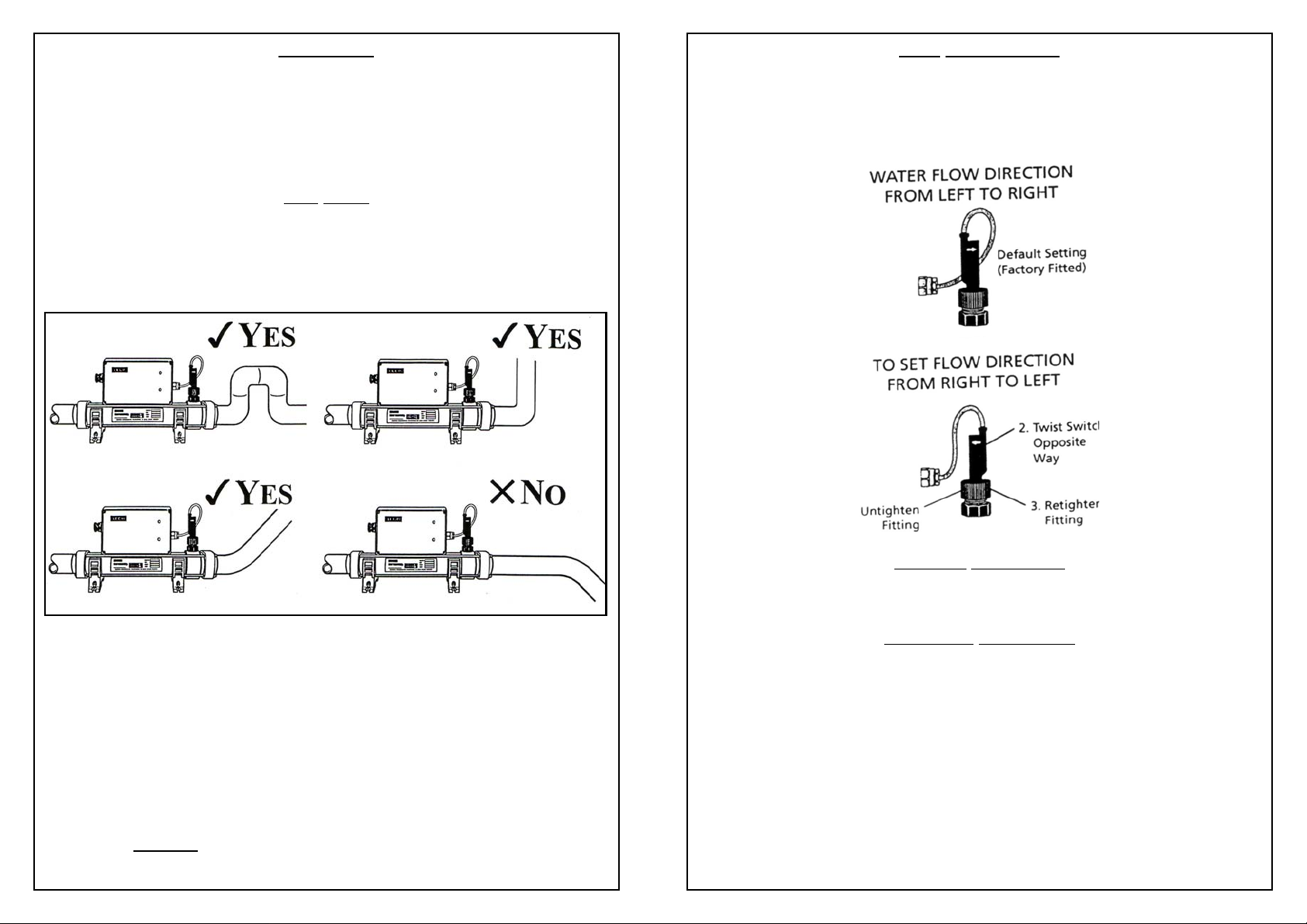
To assist in air purging and ensure the heater remains completely full of water, the return pipe which exits the heater
MUST incorporate a safety loop, installed close to the heater, of an inverted U-shape in which the pipe rises 60-mm
above the heater’s outlet port. (see illustration below).
IMPORTANT
ALL INSTALLATIONS MUST INCORPORATE A SAFETY LOOP OR INVERTED ‘U’ IN THE PIPE WORK
EXITING THE HEATER. THIS MUST BE INSTALLED AS CLOSE AS POSSIBLE TO THE HEATER.
WHEN COUPLING TO FLEXIBLE PIPE WORK THIS CAN BE ACHIEVED BY
ROUTING THE PIPE UP AND OVER AN OBSTACLE.
To allow coupling to flexible pipe work your heater is supplied with hosetail adaptors (Models 2-kW to 9-kW)).
The hosetail threads must be made watertight using PTFE tape or silicon sealant (RTV). Flexible pipes must be
securely clamped to the hosetails using a
jubilee clip or similar.
Diagrams assume water flow fr om left to right. Note that the lift in the pipe work shown in the
diagrams must ALWAYS
to left, the lift in the pipe work must be installed at the opposite end of the heater to that shown
in the diagram.
be installed on the outlet of the heater I.e. with water flow from right
WEATHER PROTECTION
The heater should be installed within a dry weatherproof enclosure.
If the heater is not used during winter months, it must be drained to prevent frost damage.
ELECTRICAL CONNECTION
The heater must be installed in accordance with the latest IEE wirin g regulations, which stat e that the work must be
carried out by a qualified electrician, who will provide a certificate of conformity upon completion of the work. The
power supply must be fitted with a 30-mA circuit breaker (RCD).
Cable section: should be calculated at 5-amp / mm² for distances up to 20 metres (these sections are indicative and
should be checked and adapted if necessary for cable lengths ove r 20 metres).
CAUTION
The water quality must be within the following limits:
PH 6.8-8.0
Chloride Content MAX: 150-mg/litre
Free Chlorine: 2.0-mg/litre
Total Bromine MAX: 4.5-mg/litre
The 800 Series heater is NOT Suitable for use with salt water.
 Loading...