


User's Guide of M.NT68676.2A Controller
Board
V1.1
2014-03-28
ELECREALM
http://www.elecrealm.com/

http://stores.ebay.com/elecrealm/
1 / 27
Content
Chapter 1--Cable connection ..................................................... 2
Chapter 2--The LCD Panel Voltage Jumper .............................. 6
Chapter 3--How to enter into factory mode ............................... 8
Chapter 4--Upgrading the M.NT68676.2A firmware............... 16
Chapter 5--Troubleshooting..................................................... 26

http://stores.ebay.com/elecrealm/
2 / 27
Chapter 1--Cable connection

http://stores.ebay.com/elecrealm/
3 / 27
Please check the inserting condition of each foot. If some foot is not fully inserted (as
shown in the figure below), please use tweezers to press the exposure to the top of the
foot, let all feet be inserted into
well.

http://stores.ebay.com/elecrealm/
4 / 27

http://stores.ebay.com/elecrealm/
5 / 27

http://stores.ebay.com/elecrealm/
6 / 27
Chapter 2--The LCD Panel Voltage Jumper
The board voltage and the LCD voltage are 2 different parameters. The board can be
worked from +5V to +12V. The LCD voltage only can be supplied by the board’s
jumper with only +3.3V +5.0V +12.0V. Most of LCD panel works at +3.3V. Normally,
the board’s jumper has been jumped to +3.3V and please don’t jump it again. Or else,
the LCD will be damaged at +5.0V/+12.0V.

http://stores.ebay.com/elecrealm/
7 / 27

http://stores.ebay.com/elecrealm/
8 / 27
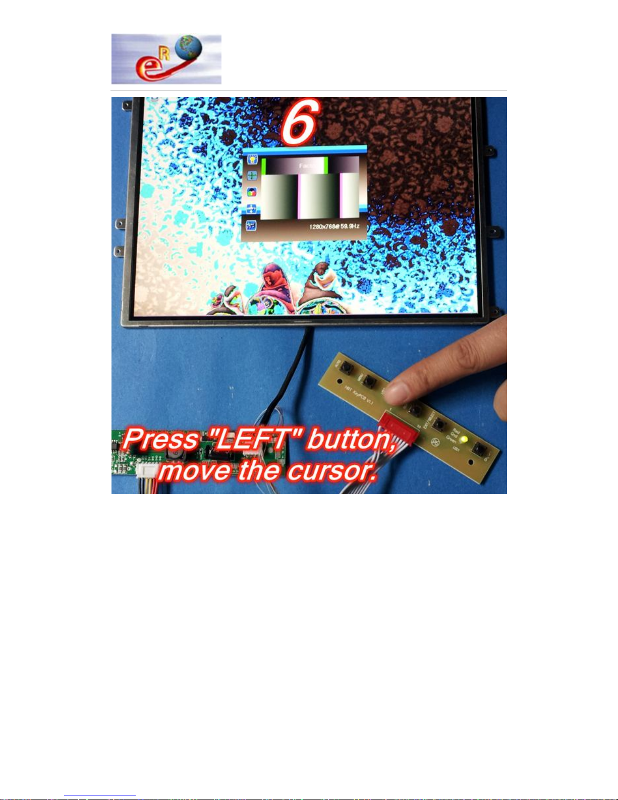
Chapter 3--How to enter into factory mode

http://stores.ebay.com/elecrealm/
9 / 27

http://stores.ebay.com/elecrealm/
10 / 27

http://stores.ebay.com/elecrealm/
11 / 27
]

http://stores.ebay.com/elecrealm/
12 / 27
http://stores.ebay.com/elecrealm/
13 / 27

http://stores.ebay.com/elecrealm/
14 / 27

http://stores.ebay.com/elecrealm/
15 / 27

http://stores.ebay.com/elecrealm/
16 / 27
Chapter 4--Upgrading the M.NT68676.2A
firmware
Tools:
VGA Cable—1pcs
Parallel Programmer--1pcs
Parallel Cable—1pcs
The steps:
Please confirm your PC has been installed the Parallel port driver program. If it
isn’t installed, please install it first.
Step 1. Installed the Parallel port driver program on the PC.

http://stores.ebay.com/elecrealm/
17 / 27
Step 2. Connect the cables as follows.

http://stores.ebay.com/elecrealm/
18 / 27

http://stores.ebay.com/elecrealm/
19 / 27

http://stores.ebay.com/elecrealm/
20 / 27
Step 3. Double click the Easy WriterV2011.0831_W7.exe file to start software driver
installation. Then, the setup program will guide user to complete software
installation.

http://stores.ebay.com/elecrealm/
21 / 27
Step 4. Then run EasyWriter_V2010 software, a new dialog popped up as below.
Press button, and select .

http://stores.ebay.com/elecrealm/
22 / 27
Step 5. Then press , a new dialog popped up as below. Press the left
button and finish the software configuration.
Step 6. Press Option, remove the selection of .

http://stores.ebay.com/elecrealm/
23 / 27
Step 7. Press Load File, a new dialog popped up as below. Select the bin file on the
PC.

http://stores.ebay.com/elecrealm/
24 / 27
Step 8. Press to burn bin file to the driver board.

http://stores.ebay.com/elecrealm/
25 / 27
图 6
Step 9. A new dialog popped up as below, the total process finished.
Step 10. If the upgrading procedure is failed, please press ,then
press , then press and re-burn the bin file to the board.

http://stores.ebay.com/elecrealm/
26 / 27
Chapter 5--Troubleshooting
Question 1 – The power adapter requirement of the board.
The board voltage and the LCD voltage are 2 different parameters.
The board can be worked from +5V to +12V with 3.0A current.
Question 2 – The LCD panel voltage
The LCD voltage only can be supplied by the board’s jumper with only +3.3V +5.0V +12.0V.
Most of LCD panel works at +3.3V. Normally, the board’s jumper has been jumped to +3.3V and
please don’t jump it again. Or else, the LCD will be damaged at +5.0V/+12.0V.
Question 3 – How to confirm all the connections are in good condition.
First of all, please do not input any signal cable.
Then power on the board via keyboard power ON/OFF button.
The following image can be shown on the LCD. That means the board kits and LCD are in
good condition. Then you can start use it via plugging in the signal cable.
If the “ATTENTION NO SIGNAL” isn’t shown on the LCD, there should be problems and
please don’t connect the signal cable to the board in order to save time. Please check the board
power, the LVDS cable connection to board and to the LCD.
 Loading...