

Page 1

ELECRAFT XG50 SIGNAL SOURCE
Ref
Qty
Description
Part #
R1 1 Res, 5.1K Ω 1% (grn, brn, brn, brn, brn)
E500109
R2 1 Res, 10 Ω 5% (brn, blk, blk, gold)
E500054
C1,C2
2
Cap, 0.1 uF, 50V 20% mono
E530020
J1 1 2.1mm power connector
E620026
J2 1 BNC Jack right angle
E620020
U1 1 LM78L05 5 volt regulator
E600029
U2
1
49.380 TCXO ±5 ppm
E660033
PCB
1
XG50 Printed Circuit Board
E100451
1
Power Cable
E980171
Rev D , N o v emb e r 26, 2 0 1 2
Copyright © 2012, Elecraft, Inc., All Rights Reserved
The Elecraft XG50 is a simple 49.380 MHz signal source specifically designed for use with the KX3 Extended
VFO Temperature Compensation Procedure. Powered from a 12VDC source, the XG50 produces a stable -36
dBm signal.
Specifications
RF Output Level 10 mv p-p (-36 dBm) into 50 ohms
Frequency 49.380 MHz, ±5 ppm
Stability Approximately ± 2 Hz
Current Drain Less than 25 ma @ 12 VDC
Operating Voltage 8 – 15 VDC
Size PC board: 2.5"L x 1"W; 3.3"L including BNC connector
Parts Inventory
†
Assembly
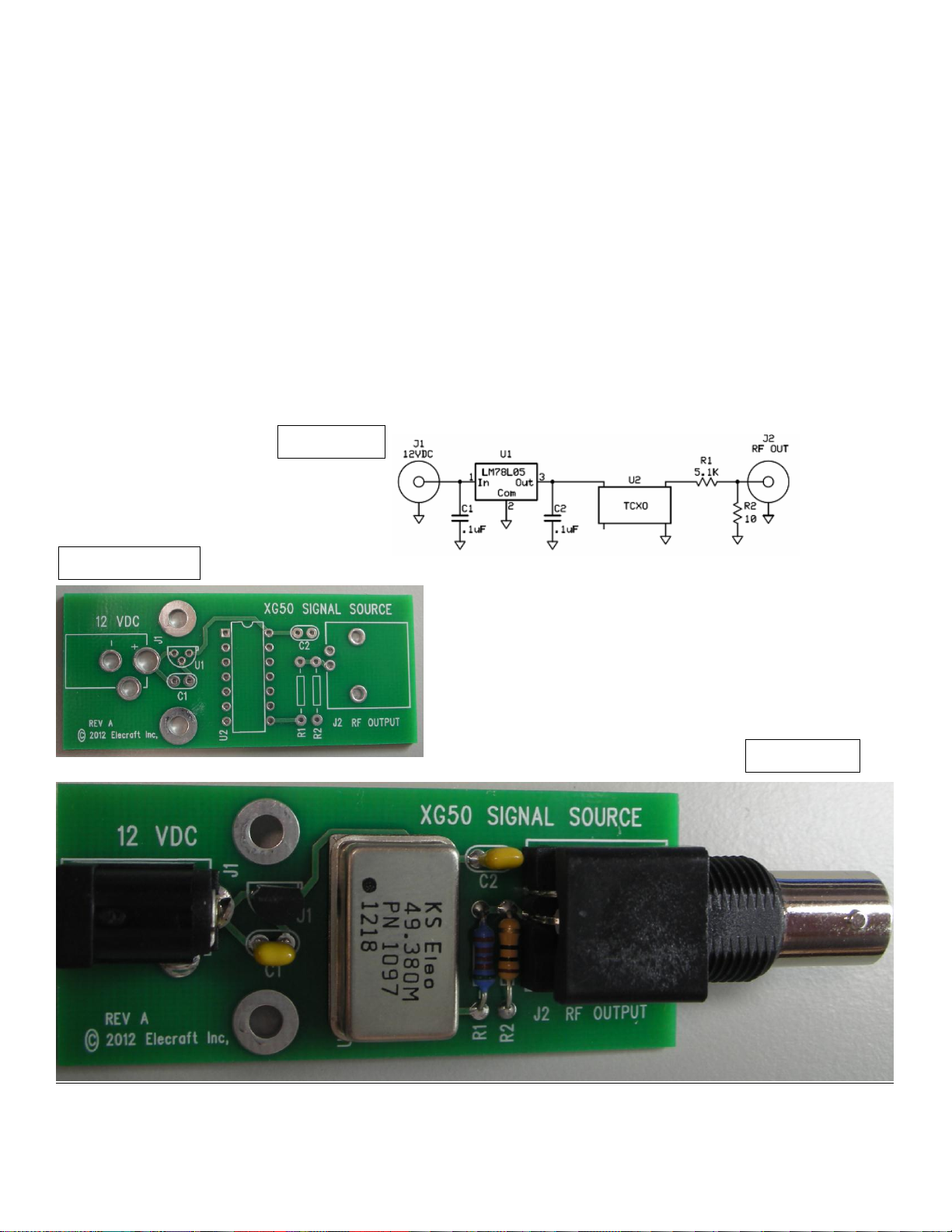
Orient the printed circuit board with the silk-screened side up and the title “XG50” at the top.
Install R1 and R2 at the indicated positions.
Install C1 and C2 at the indicated positions.
Install U1 at the indicated position, being careful to orient the flat on the device so it matches the silk
screen outline.
Install U2 at the indicated position. The black dot on the device denotes pin 1. When correctly inserted
into the board, this dot will be oriented closest to the square PIN 1 hole.
Install J2, the BNC connector at the position indicated on the PC board silkscreen
Install J1, the power connector at the indicated position on the PC board silkscreen.
†
After initial 8 hour aging period.
1
Page 2
Initial Test
Schematic
Bare Board
Assembled
Observing polarity, attach 12 VDC to the unit using the supplied power cable, inserting the plug into J1.
Using a frequency counter or oscilloscope, verify an output of 49.380 MHz ± 247 Hz.
A transceiver tuned to 49.380 MHz or VHF radio tuned to the 3
be used to verify operation.
rd
harmonic of 148.140 MHz may also
Using the XG50
Prior to initial use, power the XG50 for 8 hours. This should only be done once and while not required
for normal operation, will help minimize oscillator drift. When using the XG50 as part of the KX3
Extended Temperature Compensation Procedure, locate it away from the radio, in an area free from
drafts and heat sources. This will help minimize frequency drift during the procedure. A 3’ (1 M) 50
ohm patch cable may be used to connect the output of the XG50 to the KX3.
2
 Loading...