

Page 1

ELECRAFT
PX3
H
IGH-PERFORMANCE
P
ANADAPTER
OWNER’S MANUAL
Revision A2, October 1, 2014
Copyright © 2014, Elecraft, Inc.
All Rights Reserved
Page 2

For Owners of the Elecraft K3
Transceiver and P3 Panoramic Display:
The PX3 has nearly all of the same features as the
P3*, including the same high-resolution color display,
2 to 200 kHz SPAN, fast sweep rates, and eight
programmable “hot keys” to do quick setup. The
primary difference between the two is in the interface
to the transceiver. The P3 digitally down-converts the
K3’s 8.215-MHz I.F. signal, while the PX3 uses
quadrature baseband demodulation (I/Q) to convert
signals from the KX3’s RX I/Q output jack. The
PX3’s method requires less interface and
demodulation circuitry, resulting in a significantly
lower-cost unit with lower power consumption
(consistent with portable use). For details on how
baseband I/Q demodulation impacts performance, see
PX3 Compared to the P3 and PC-Based Panadapters
on page 32
* “Fixed tune" mode is not yet available in the PX3.
If this feature is added at a future date, it may have
somewhat different performance than in the P3, in
terms of displayed bandwidth and allowed offset from
the currently-tuned frequency.
2
Page 3

Contents
If you purchased the PX3 Kit, go directly to page 35 to assemble your PX3
Key to Symbols and Text Styles ...................... 4
In the Box ........................................................ 5
Serial Data Cable ................................................. 5
PX3-KX3 Interface Cable (PX3CBL) ................. 5
DC Power Cable (E850524) ................................ 5
Quick-Start Guide ............................................ 6
Introduction .................................................... 10
PX3 Features ..................................................... 10
Easy Set-Up ................................................... 10
Display .......................................................... 10
Ergonomic Design ......................................... 10
Field Upgradable ........................................... 10
Front Panel ..................................................... 11
Control Groups .................................................. 11
Display .............................................................. 12
Primary Controls ............................................... 12
Menu ................................................................. 13
Programmable Function Keys ........................... 13
Side Panel Connectors ................................... 14
Basic Operation ............................................. 15
Using Tap/Hold Switches ................................. 15
Initial Power-Up ................................................ 15
Configuring the Display .................................... 15
Using the Menu ................................................. 15
Programmable Functions .................................. 15
Adjusting the Amplitude ................................... 16
Adjusting the Frequencies Displayed ................ 16
Using Markers ................................................... 16
Waterfall Markers ............................................. 17
Using Cursors .................................................... 17
Noise Blanker .................................................... 18
How to Set Up and Interpret the PX3 Display
....................................................................... 19
Spectrum Display .............................................. 19
Waterfall Display .............................................. 20
Averaging and Peak Hold ................................. 20
Span ................................................................... 20
Typical Spectra .................................................. 20
Advanced Operating Features ........................ 22
Remote-Control Commands .............................. 22
PX3 Utility Program ......................................... 22
Configuring the Power Switch .......................... 22
Firmware Upgrades ........................................ 23
Checking your Firmware Revision ................... 23
Forcing a Firmware Download ......................... 23
Updating KX3 Firmware .................................. 23
Opposite Sideband Nulling ............................ 24
Getting Ready ................................................... 24
Setting up the PX3 and KX3 to use the PX3
Internal Calibration Signal ................................ 27
Menu Functions ............................................. 28
PX3 Menu ......................................................... 28
Troubleshooting ............................................. 30
Power On/Off Issues ......................................... 30
Display Issues ................................................... 30
Parameter Initialization .................................. 31
PX3 Compared to the P3 and PC-Based
Panadapters .................................................... 32
Theory of Operation ....................................... 33
RS-232 Serial Interface Cable ....................... 34
Kit Assembly Instructions ............................. 35
Preventing Electrostatic Discharge Damage ..... 35
Tools Required ................................................. 35
Parts List ........................................................... 36
PX3 Front Panel Assembly Bag E850621 .... 36
Individually Wrapped Components .............. 36
PX3 Misc Bag - E850615 ................................ 37
PX3 Hardware Envelope – E850614 ................ 38
Assembly Procedure ......................................... 39
Overview of the Kit ...................................... 39
Servicing the PX3 .......................................... 50
Accessing the PC Boards .................................. 50
Cleaning the LCD Bezel ................................... 50
Replacing the LCD ........................................... 51
Specifications ................................................. 52
Customer Service and Support....................... 53
Technical Assistance .................................... 53
Repair / Alignment Service .......................... 53
Elecraft manuals with color images may be downloaded from
www.elecraft.com
3
.
Page 4

Key to Symbols and Text Styles
Identifies important information.
Operating or kit assembly tip.
-100
DISP
AVERAGE
MENU:Font
Characters displayed on the LCD screen
Tap switch function (labeled above a switch)
Hold switch function (labeled below a switch; hold for 1/2 sec. to activate)
Typical menu entry
4
Page 5

In the Box
In addition to the PX3 display itself, check the shipping box for the following contents.
Serial Data Cable
Connects the PX3 to a serial port on your personal computer to upload updated firmware and provide other
functions. If needed a serial cable with an RS232 interface is available (order the KXSER). These cables are
identical to and interchangeable with the serial interface cable used with the KX3 transceiver. If desired, you can
make your own RS232 serial interface cable. See page 34 for the schematic diagram.
PX3-KX3 Interface Cable (PX3CBL)
Connects the PX3 to your KX3 (See Figure 2 on page 8 or Figure 3 on page 9).
Do not substitute different or longer cables for the PX3CBL set supplied. Doing so may degrade the
performance of your PX3. See PX3 Compared to the P3 and PC-Based Panadapters on page 32 for details.
DC Power Cable (E850524)
Connects the PX3 your 9 to 16 Vdc power supply with tinned leads to connect to your power supply. Optionally
you can purchase the PX3 DC Power Supply that plugs into a mains outlet as shown below. Order the
(PWR121A-US).
The optional power supply comes with a right angle extension (PWR2.1RA)
5
Page 6
Quick-Start Guide
To get started using your PX3 right away, please read this page and the pages that follow, to connect your PX3
to your KX3 and explore the features and controls.
Figure 1. PX3 Front Panel.
Prepare your
KX3
Ensure your KX3 is equipped with Firmware version 2.19 or later: See your KX3 Owner’s
Manual for information about checking and updating the firmware if needed.
In the KX3 menu, set RX I/Q: On and exit the menu.
Setup and
Connections
Position the KX3 and PX3 as shown in the photograph on the cover, with the PX3 on the left
side of the KX3. This keeps the PX3 away from the RF fields around the KX3’s antenna
connectors that can interfere with the PX3.Do not substitute longer cables for the PX3CBL set
provided. Doing so may allow noise pickup from various sources, including switching power
supplies, 60-Hz AC, ground loops, and interface cables. You can pass the PX3CBL cables
connecting the KX3 and PX3 under or behind the PX3.
When adjusting the legs to position on your PX3, be sure the thumb screws are loose.
They thread into the legs, and forcing a leg into position without loosening the thumb
screw may tighten the thumb screw so much it becomes very difficult to loosen.
Connect a dc power supply to the
Specifications, page. 10 for more about the power requirements). A power cable with a right
angle 2.1 mm barrel connector is supplied. Connect the wire with the white strip to the positive
(+) terminal on your power supply. If you purchased the optional PWA121V1A-US power
supply for your PX3, plug it into a 100 to 240 volt mains outlet. It is provided with a rightangle cable adapter (PW2.1RA) that you can use for a neater cable installation.
We recommend that you turn off the external supply before connecting power to the
PX3. Some power connectors have an exposed center terminal that can create a short
circuit if it touches the metal ground when it is being inserted.
If your KX3 installation includes the Elecraft KXPA100 amplifier connected using the
KX3 to KXPA100 Adapter Cable, connect the PX3 as shown in Figure 3on page 9.
If you do not have the KXPA100 and adapter cable, connect the PX3 as shown in Figure
2 on page 8.
9-16 VDC input jack on the PX3 side panel (see
6
Page 7
The Basics
Other
Features
TAP AND HOLD: Most PX3 switches have two functions, similar to the KX3.Tap (press
briefly) to activate the function labeled on the switch. Hold (press for 1/2 second) activates the
function labeled below the switch. In the text, tap functions are shown like this:
DISP while a
hold function is shown like this: AVERAGE. Additional typographical conventions are shown
on the previous page.
The controls and indicators shown in Figure 1 are identified by the circled numbers in the
following text (e.g.
Apply power to the PX3 and tap
refers to the display screen).
PWR
to turn it on.
Tap DISP to cycle between spectrum and waterfall display modes (Page 15).
Activating many functions enables the SELECT knob so you can adjust the
parameter associated with the function. The current parameter value is shown on the screen
. You can exit and save the parameter by tapping the same key a second time, even for
hold functions.
For hold functions, you can also hold the key a second time to exit parameter-entry mode.
Holding the four keys along the right edge of the front panel
, , , , a second time
de-activates the function itself. For example, holding CENTER a second time returns
the display center frequency to the transceiver frequency and holding MKR B a second
time turns off marker B.
Tap MENU
and use the
SELECT knob to scroll through the menu.
Tapping the SELECT knob while the menu is active causes the currently-selected
menu function to execute. For example, select
LCD Brt from the menu and tap the knob.
The knob now adjusts the brightness of the LCD display backlight. Tap the knob again to
exit the selection or tap
MENU
to select a different menu item. Some menu items are
toggle functions. Instead of changing the parameter by turning the SELECT knob, it
changes automatically whenever the knob is tapped. The new value is displayed briefly
near the top of the spectrum display. Menu items are listed on page 28.
As you become familiar with the menu options, you may find that you want to adjust
certain items frequently. You can assign up to eight menu items to the function keys
, , , . Tap FN1 through FN4 or hold FN5 through FN8 to assign the function key
to a menu item while the menu item is displayed.
Hold LABELS
to display the labels you have assigned to the switches (page 15). They
are displayed at the bottom of the screen, just above the function keys (Pages 12 and 13).
Hold LABELS
Tap MKR A or hold MKR B
again to toggle the labels off.
to turn on marker A or B. Rotate the
SELECT knob to
place the selected marker at a desired frequency on the display. Markers may be used to
measure the frequency of an interesting signal and tapping the
(change the frequency of) the KX3 to that frequency.
MKR A controls the KX3's VFO A
SELECT knob will QSY
and MKR B controls VFO B. The marker colors match the corresponding VFO cursors to
emphasize the correspondence. Whichever marker is currently selected is the one that
causes the KX3 to QSY (Page 12).
To return from the last QSY to the original frequency ("undo" function), hold the
SELECT knob pushbutton while the marker is selected.
To turn off the markers, tap MKR A while marker A is selected or hold MKR B while
marker B is selected.
7
Page 8
Tap
Hold CENTER
Tap
Hold SCALE
Hold AVERAGE to turn on display averaging and allow adjustment of the averaging
SPAN
displayed at the top (left and right edge respectively) of the spectrum window (Page 13).
(Page 13). This function may be disabled by selecting
SELECT knob pushbutton to toggle between CENTER Key ON and CENTER Key OFF.
REF
displays. The reference level is the signal level corresponding to the bottom of the
spectrum display (Page 13).
waterfall displays. For example, Scale (dB): 60 means that the bottom of the display is 60
dB below the top (Page 13).
time by turning the
to set the frequency span of the display. The start and stop frequencies are
and turn the
to set the amplitude reference level of both the spectrum and waterfall
to set the scale, or signal amplitude range, of both the spectrum and
SELECT knob (Page 13).
SELECT knob set the center frequency of the display
MENU:CenterEn and tapping the
Figure 2. Basic KX3-PX3 Cabling.
8
Page 9

When used with the KXPA100 Amplifier as shown here, the PX3 RS232 data rate must be set
to 38400 baud (see menu entry RS232 on page 29).
Figure 3. PX3 Signal Cabling with KXPA100 Amplifier and KX3 to KXPA100 Adapter Cable.
.
9
Page 10

Introduction
This comprehensive manual covers all the features and capabilities of the Elecraft PX3 panoramic display. We
recommend that you begin with the Quick-Start Guide (page 6). The Front Panel (page. 11) and Side panel
Connectors (page 14) sections are for general reference. Basic Operation (page 15) and Advanced Operating
Features (page 22) fill in the details of the full capabilities of the PX3.
PX3 Features
The PX3 Integrates very closely with the Elecraft KX3 with point-and-click QSY and an “undo” feature with
simple control press to return to the previous frequency. A number of advanced features enhance the PX3’s
performance and versatility:
Easy Set-Up
Only three cables for basic operation (I/Q for signal, ACC1 for frequency data and power). Cables are
provided with the PX3.
Optional additional connections provided for transceiver communications, a personal computer and
optional accessories.
Simple configuration and calibration for optimum performance with your KX3.
Display
Bright, high-resolution, full color display.
Efficient LED backlight for long life and low power consumption.
The frequency display tracks the KX3.
Both Spectrum and Waterfall display s.
Fast display update.
Up to 200 kHz span.
Frequency resolution automatically increases as span is decreased.
Excellent sensitivity and dynamic range.
Ergonomic Design
Uncluttered interface.
No unused controls on the screen.
Adjustable legs to match the viewing angle of the KX3.
Field Upgradable
Software defined architecture so many new features will require only a simple firmware update using the
provided PX3 utility program that can be downloaded from www.elecraft.com.
10
Page 11

Front Panel
This section describes all front panel controls and the liquid crystal display (LCD). Operating instructions are
covered in later sections.
Figure 4. PX3 Control Groups.
Control Groups
Primary Controls (see page 12): These switches
are hard-coded with permanent function
assignments. They provide the most important
operational features needed for basic panadapter
operation, including display options, amplitude
scaling, frequency control and markers.
Programmable Function Switches (see page 13):
The function keys may be assigned to any of the
functions in the
operational features, test functions, and setup and
calibration routines.
MENU list. These include less-used
11
Page 12

Display
The 480x272-pixel, color TFT-LCD display is used
both for the panadapter spectrum and waterfall
graphics as well as for general-purpose information
needed by the operator. All graphics and text are
bit-mapped and so are software-defined. The
display brightness and the text size can be changed
via
MENU entries (Page 28).
Figure 5. PX3 Display.
Primary Controls
PWR turns the PX3 on or off. The PX3 may be
configured to turn on automatically whenever
power is applied by moving a jumper inside the
PX3 enclosure (see Configuring the Power Switch
on page 22for details). Holding the
more than 20 seconds places the PX3 in boot-load
mode, ready to receive new firmware. If you do this
accidentally, simply cycle the
again to restore normal operation.
MKR A and MKR B each cause a marker to appear
on the display, using different colors for A and B.
MKR A controls the KX3's VFO A and MKR B
controls VFO B. The marker colors match the
corresponding VFO cursors to emphasize the
correspondence.
The
symbol next to the marker frequency means
the frequency can be adjusted by selecting it with
the MKR A or MKR B switch and turning the
PWR switch for
PWR off, then on
SELECT knob. Tapping the SELECT knob
changes (QSY) the frequency of the corresponding
KX3 VFO to the marker frequency. To undo the
QSY and return to the original VFO frequency,
select the marker and hold the
SELECT knob
pushbutton.
To turn off markers, tap
MKR A while marker A is
selected or hold MKR B while marker B is selected.
When a marker is turned back on after having been
turned off, it will come back at the same frequency
unless it is off-screen, in which case the marker
defaults to the center frequency.
When another function that uses the
SELECT
knob is activated, the marker(s) will stay visible and
when that other function is de-selected the last
active marker automatically becomes active again.
12
Page 13
SPAN sets the frequency span of the display. The
available range is 2 kHz to 200 kHz. The start and
stop frequencies are displayed at the top (left and
right edge respectively) of the spectrum window.
For example, a 200 kHz span will be displayed with
-100.0 in the upper left and +100.0 in the upper
right corners.
CENTER sets the center frequency of the display,
which is also displayed at the top center of the
spectrum window. The center frequency of the
display may be offset from the KX3’s frequency
with the
SELECT knob. The center frequency
will then track changes in the KX3’s frequency,
maintaining the same offset.
Menu
MENU accesses an alphabetical list of functions
(see Menu Functions, page.28). Scroll through the
list with the
select an item. For items with only two or three
values, tapping the
between the parameter values. For other items, turn
the
SELECT knob to choose the parameter value.
Tapping the
selects the item and exits the menu. If you wish to
terminate the item but keep the menu active, tap
MENU. When you wish to exit the menu, tap
MENU again.
SELECT knob and tap the knob to
SELECT knob toggles
SELECT knob a second time un-
Hold CENTER a second time to return the center
frequency to the KX3's VFO A frequency.
This function is disabled if
MENU:CenterEn is set
to OFF.
REF sets the amplitude reference level of the
display, both spectrum and waterfall. The reference
level is the signal level in dBm that corresponds to
the bottom of the spectrum display and the
minimum (dark blue) signal level of the waterfall
display. The amplitude labels that appear along the
left edge of the spectrum display may be in S-units
plus dB over S9 or dBm, depending on the setting
of
MENU:Lvl Mode. The KX3's attenuator and
preamp have no affect on the displayed amplitude
when dBm is selected, but the effect of the
attenuator and preamp will be seen when the
display is in S-units.
SCALE sets the scale, or range, of both the
spectrum and waterfall displays. For example,
Scale (dB):
60
means that the bottom of the
display is 60 dB below the top.
DISP toggles between the spectrum, and
combination spectrum/waterfall display modes.
Programmable Function Keys
Most menu functions can be assigned to a function
key by tapping FN1 through FN4 or holding FN5
through FN8 while the menu item is displayed but
not selected. When a menu function is selected, the
text on the screen prompts you to either tap the
knob to select it or a FN key to assign it to the key.
If a function was previously assigned to a key,
assigning a new function over-writes the original
function.
LABELS displays the function assigned to each
key. Keys identified with the label FN number have
not been assigned to a menu function. LABELS
toggles the function key labels on and off. Note that
the function keys are still active even when the
labels are turned off.
AVERAGE allows you to turn on and adjust display
averaging. The averaging is adjusted in units of
display update periods. For example,
time:
every 20 update cycles. Tap
20 means the display is averaged over
DISP to exit the
Averaging
average parameter adjustment mode while
maintaining the selected averaging period. Hold
AVERAGE to turn off averaging.
13
Page 14

Side Panel Connectors
Figure 6. PX3 Side Panels.
See Figure 2 on page 8 or on page 9 for normal cable interconnections between the PX3 and KX3.
The following describes the function and pin-out of each connector.
Power: 9-16 VDC is a standard 2.1 mm barrel connector for dc power. The center pin is the positive (+)
connection.
ACC1 PC is a 3.5 mm stereo jack that allows firmware updates, configuration, and remote control of the PX3
and KX3 via a personal computer. The tip connection is RX data coming from the computer and the ring is data
going to the computer. If needed, suitable cables for either a USB or RS232 computer interface are available
from Elecraft (see Firmware Upgrades on page 23 for more information).
ACC1 XCVR is a 3.5 mm stereo jack that allows communications between the PX3 and the KX3. When the
PX3 is turned off, data applied at ACC1 PC passed directly through the PX3 to the ACC1 XCVR connector.
The tip connection is RX data going to the KX3 and the ring is data coming from the KX3.
RX I/Q XCVR is a 2.5 mm stereo jack that receives quadrature outputs from the KX3 receive mixer (I=inphase, Q=quadrature).
RX I/Q PC is a 2.5 mm stereo jack that provides the quadrature (I/Q) outputs from the KX3 to a personal
computer. If you had a I/Q connection directly to the KX3 before installing the PX3, this connector feeds the
same signals through to your computer with the PX3 installed.
KEYBD is for future use.
CALIBRATOR SIGNAL OUTPUT on the right side panel is a single pin output that provides a signal
required to adjust the opposite sideband nulling for your KX3 (see page 24).
14
Page 15
Basic Operation
This section covers the fundamentals of PX3
operation. Once you're familiar with the PX3,
please go on to Advanced Operating Features
(page 17).
Using Tap/Hold Switches
Most PX3 switches have two options. Tapping
(pressing for less than 1/2 second) activates the
function labeled in white on the switch. Holding
(pressing for more than 1/2 second) activates the
function labeled in yellow below the switch.
Initial Power-Up
Connect your PX3 to the KX3 as shown in
Figure 2 on page 8 or Figure 3 on page 9.
Apply power to the KX3 and enable operation
with the PX3 in the KX3’s menu:
I/Q On
Press PWR to turn the PX3 on, if it is not on
already. The screen should light and you should
see a spectrum or combined spectrum and
waterfall display. If a KX3 is connected via the
ACC1 cable you should see the correct
frequency at the top center of the display.
MENU: RX
Using the Menu
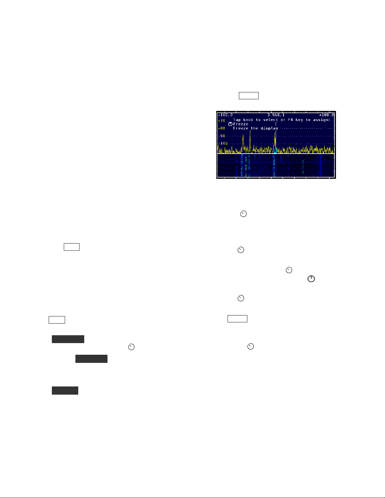
Tap MENU to access the menu. The menu
will appear near the top of the display .
Figure 7. Typical Display Showing a Menu
Selection.
Turn the
alphabetical list of available menu functions, as
documented in the Menu Functions section
(page.28).
Tap the
Most functions have a parameter which can
then be changed with the
Those functions all start with the
the display.
SELECT knob to scroll through an
SELECT knob to select a function.
SELECT knob.
symbol on
Configuring the Display
Tap DISP to cycle between spectrum and combined
spectrum and waterfall displays.
Hold AVERAGE to turn on averaging and to set the
averaging time constant with the
You can hold AVERAGE again to turn off
averaging or just tap the same switch to clear the
parameter-entry text from the display while leaving
averaging enabled.
Hold LABELS to show or hide the function switch
labels.
There are also several MENU functions that
configure the display, such as LCD Brt (display
brightness), Peak hold, Freeze display, Font size
and Waterfall height.
SELECT knob.
Tap the
function.
Tap
Some menu items are toggle functions. The
parameter changes automatically every time
you tap the
SELECT knob again to exit the
MENU again to exit the menu.
SELECT knob.
Programmable Functions
Most menu functions can be assigned to any
programmable function switch, FN1 to FN8 to
allow quick access without using the menu.
Common examples of such functions you may wish
to access quickly are
15
Peak hold and Freeze display.
Page 16
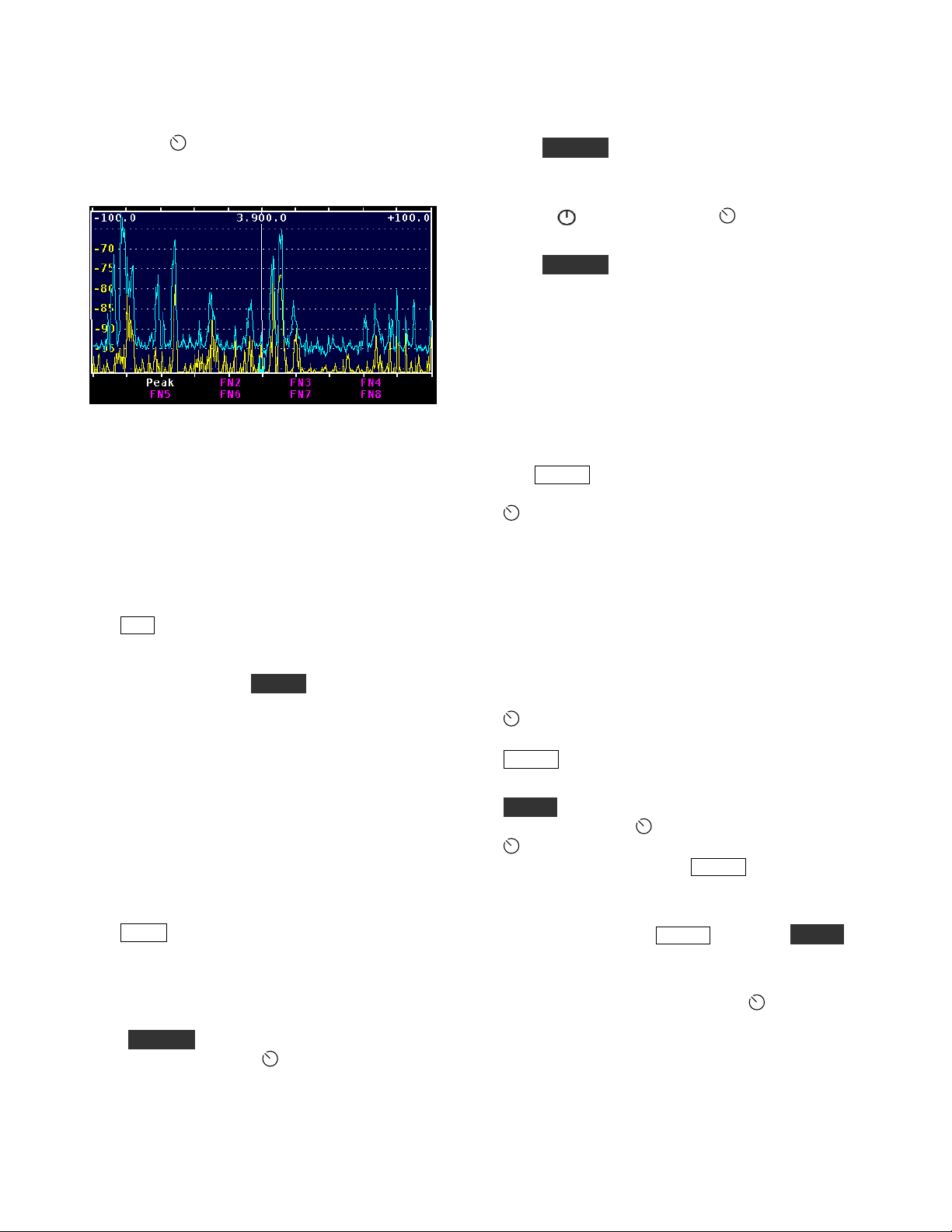
Tap or hold the desired function switch while the
function is visible on the display but not selected by
tapping the
then becomes the function switch label which can
be seen if labels are currently displayed.
Figure 8. PEAK assigned to Function Switch FN1.
Assigning a function to a previously-assigned key
overwrites the previous function. Optionally you
can remove any assignment from a function switch
with
MENU:FN Erase and tap or hold the function
switch you wish to erase.
SELECT knob. The function name
Adjusting the Amplitude
Tap REF to adjust the reference level, which is the
signal level that corresponds to the bottom of the
spectrum display and the low-signal level of the
waterfall display. Hold SCALE to adjust the
"vertical gain" of the display. For example if the
reference level is set to -100 dBm and the scale to
30 dB, then the top of the spectrum display is at -70
dBm and the bottom at -100 dBm.
The waterfall display is most useful if the reference
level is adjusted to place the noise level near the
bottom of the display and the scale is adjusted so
that the strongest signals of interest are near the top.
Adjusting the Frequencies Displayed
Tap SPAN to adjust the range of frequencies that
can be seen on the display at one time. The start and
stop frequencies in KHz are indicated at the top left
and right of the display. They are shown as offsets
from the center frequency.
Hold CENTER to adjust the display center
frequency by turning the
center frequency of the display is now offset from
the KX3’s VFO A frequency by the amount shown.
SELECT knob. The
The center frequency will then track changes in the
KX3’s frequency, maintaining the same offset.
Hold CENTER a second time to return the center
frequency to the KX3’s VFO A frequency.
The center function may be disabled in the menu:
MENU: CenterEn. Press the SELECT knob to
toggle the function on or off.
Hold CENTER again to re-center the display on the
transceiver VFO frequency.
The tic marks that appear along the top and bottom
edges of the spectrum and waterfall widows
indicate RF frequency in integer multiples of 0.5, 1,
2, 5, 10 or 20 kHz, depending upon the span.
Using Markers
Tap MKR A to turn on marker A and allow you to
change the marker frequency by rotating the
SELECT knob. To determine the frequency of a
signal, move the marker so that it overlays the
carrier and read the frequency from the display. For
single sideband signals, place the marker where the
carrier would be if it were transmitted, i.e. on the
lower frequency (left) edge of an upper sideband
signal and on the upper frequency (right) edge of a
lower sideband signal.
You can QSY (change the frequency of) the KX3’s
VFO A to the marker A frequency by tapping the
SELECT knob. To return to the previous
frequency, hold the knob. To turn off marker A, tap
MKR A again.
Similarly, marker B is turned on and off with the
MKR B switch and you can change the marker
frequency with the
SELECT knob changes the KX3’s VFO B
frequency in the same way
VFO A frequency
To turn off a marker you must first make it active, if
necessary, by tapping MKR A or holding MKR B.
Then tap or hold the switch a second time to turn
off the marker.
If some other function that uses the
knob is activated, the marker stays on and
automatically becomes active again (you can adjust
it with the knob) when the other function is
terminated. The tap-to-QSY function affects VFO
SELECT knob. Tapping the
MKR A changes the
SELECT
16
Page 17

A if marker A is active and VFO B if marker B is
active.
When a marker is turned on, it will be at the same
frequency as the last time it was on unless that
frequency is off-screen. In that case the marker is
automatically reset to the display center frequency.
(If you lose a marker off-screen, just turn it off and
on again to return it to the center frequency.)
When you change bands on the KX3, the markers
are automatically set at the new center frequency.
Waterfall Markers
Select MENU: WfallMkrs. Tapping the
SELECT knob will turn the waterfall markers
on, causing the marker line(s) to travel down into
the waterfall display, or turn the markers off.
Figure 9. Marker A Enabled at 3563 KHz for Both
Spectrum and Waterfall.
Using Cursors
Figure 10. Bar Cursor on Upper Sideband Signal at
14.250 kHz.
Figure 11. “U” Cursor on Upper Sideband Signal at
14.250 kHz.
VFO A has a green cursor and VFO B has a
magenta cursor unless split mode is activated at the
KX3. In split mode, the VFO B cursor changes to
red as a reminder that you will transmit on that
frequency. Similarly, if XIT is on, or if split is off
and RIT is on, a new red cursor appears at the
transmit frequency.
Cursors show the position of the KX3’s A and B
VFOs, The position and width of each cursor shows
the passband being received. Two cursor shapes
may be selected using
MENU: Cursor . The
translucent bar cursor or a “U” shaped cursor at the
bottom of the spectrum display may be selected.
Figure 12. Red Bar Cursor Showing Transmit Frequency
Above the Receive Frequency.
Whenever a cursor is tuned off-screen a small
triangle of the same color appears at the bottom left
17
Page 18

or right of the spectrum window to indicate the
direction to the missing cursor
The VFO B cursor may be turned off using
VFO B. Tap the knob to select VFO B ON or
VFO B OFF as desired.
MENU:
Noise Blanker
Adjust the aggressiveness of the noise blanker with
MENU: NB Level and turn the SELECT knob.
A setting of 1 is least aggressive and 15 is
maximum. The higher the setting the more
completely it blanks the pulse noise, but the more
likely it will cause distortion of the desired signals.
Use the lowest value that does an adequate job.
About 10 or 11 is a good starting point.
The noise blanker reduces the effect of impulse
noise on the display. It has no effect on the audio
from the KX3.
Impulse noise frequently comes from such sources
as the AC power line and unshielded automobile
ignition systems.
Engage the noise blanker in the menu with MENU:
NB En. Tapping the SELECT knob toggles
the noise blanker on and off. When the noise
blanker is enabled ,
NB appears near the upper right
corner of the display after you exit the menu.
Note that the REF and SCALE settings have no
effect on the noise blanker.
If there are one or more very strong signals within
the PX3’s displayed frequency range, the noise
blanker will have a hard time detecting the
difference between the unwanted pulses and the
wanted signal. Narrow the
CENTER frequency if possible to place the strong
SPAN and/or offset the
signals well outside the PX3’s display frequency
range.
18
Page 19

How to Set Up and Interpret the PX3 Display
There are several options to customize the layout of
your PX3 display.
spectrum-only and spectrum-plus-waterfall display.
The height of the waterfall can be adjusted with
MENU: Waterfall. The function (FN) switch
labels appear at the bottom of the screen by default.
You can hide them to maximize the screen area by
holding LABELS. The FN switches remain active
even when the labels are hidden. Another trick to
maximize viewing area is to choose a smaller type
font via
MENU: Font.
DISP switches between a
Spectrum Display
The spectrum display on a panadapter is similar to
the display on a laboratory spectrum analyzer. The
horizontal axis is frequency and signal strength is
represented by the vertical height of each signal.
The PX3’s spectrum display is similar to most in
that the signal height is proportional to the
logarithm of the amplitude, represented in decibels
(dB). Each 3 dB represents a doubling of power and
10 dB means ten times the power.
The vertical scale at the left edge of the spectrum
display may be in units of dBm or S-units, as
selected by
means decibels with respect to one milliwatt. 0
dBm is one milliwatt, +10 dBm is 10 milliwatts, -10
dBm is 1/10 milliwatt and so on. An S9 signal is
normally considered to be 50 microvolts into 50
ohms, which is -73 dBm, an easy number for a ham
to remember! Assuming the standard 6 dB per Sunit, the following table applies.
MENU:
S-Units Signal Level
S9 -73 dBm
S8 -79 dBm
S7 -85 dBm
S6
S5 -97 dBm
S4 -103 dBm
S3 -109 dBm
S2 -115 dBm
S1 -121 dBm
Lvl Mode
-91 dBm
. The dBm unit
50 V
25 V
12.5 V
6.25 V
V
1.56 V
0.78 V
0.39 V
0.2 V
You would expect the S meter on the KX3 and the
signal on the PX3 display to indicate the same level,
however there are several reasons why that might
not be the case. One is that the PX3 is not affected
by the preamplifier and attenuator in the KX3 when
the signal amplitude is shown in dBm.
The noise level will generally be lower on the PX3
display compared to the KX3’s S meter. The reason
is that the effective bandwidth of the PX3 is
generally one display pixel, which is approximately
the span divided by 450. The smaller the
bandwidth, the less noise. For example, if the span
is 45 kHz, the effective PX3 bandwidth is 45,000 /
450 = 100 Hz. If the KX3 bandwidth is 400 Hz, it
will show a 6 dB (one S-unit) higher noise level
than the PX3.
A similar thing happens with spread-out signals like
SSB. Even at the maximum 200 kHz span, the
PX3’s effective bandwidth is only about 440 Hz so
that not all the SSB signal is within one pixel.
That’s why the PX3 tends to read a lower level on
SSB signals than the KX3’s S meter.
REF (reference level) on the PX3 shifts all the
signals up or down. The level that you are adjusting
is the signal level at the bottom of the display,
measured in dBm.
SCALE is used to expand or contract the vertical
scale. Think of it as a vertical gain control. The
scale is defined as the dB difference between the
top and the bottom of the display. For example, if
the reference level is -100 dBm and the scale is 20
dB, then a signal at the top of the display is at -80
dBm. For both REF and SCALE, turning the knob
clockwise makes the signals taller.
The PX3 automatically compensates for the
preamplifier and attenuator in the KX3 when the
display amplitude is shown in dBm. When you turn
them on or off, the signal levels on the PX3 should
stay the same. The indicated dBm level should be
the signal level at the KX3’s antenna input. Perhaps
counter-intuitively, this means that if you turn on
the preamplifier in the KX3, the noise level
displayed on the PX3 may decrease, rather than
increase. That is because the PX3 automatically
reduces its gain when the KX3 preamplifier is
turned on, in order to keep the signal levels the
19
Page 20

same. When the PX3 display amplitude is shown in
S-Units, the signal level will vary according to the
preamplifier and attenuator settings, just like the
KX3’s S-meter.
Waterfall Display
The waterfall allows you to see a history of band
activity for the past few seconds. Like the spectrum
display, the horizontal axis is frequency but in this
case the vertical axis is time. Signal amplitude is
represented by colors, from dark blue for weak
signals, then brighter blue as signals increase in
strength, through shades of green, yellow and red
for the strongest signals. Each horizontal line
represents one update of the spectrum display.
As each new line is written the old ones are shifted
down, creating a waterfall effect.
While the spectrum display is better at accurately
displaying signal strength and the shape of a
signal’s modulation, it can only show what is
happening right now. The waterfall is better for
showing transient signals, such as a DX station
running a pileup that only transmits for a few
seconds at a time. Often you can easily see a weak
fading signal on the waterfall that is invisible on the
spectrum display.
The scaling of the waterfall is the same as for the
spectrum. That is, the bottom of the spectrum
display corresponds to dark blue on the waterfall
and the top corresponds to bright red. For maximum
visibility of signals on the waterfall, it is best to set
REF so that the noise level is right at the bottom of
the spectrum display and then expand SCALE as
much as possible while keeping signals of interest
below the top of the spectrum display. That
improves the color contrast on the waterfall and
makes weak signals appear to pop out of the noise.
the waterfall as well by setting
to
On.
MENU:
Wfall Avg
Peak hold is a way to display a memory of past
signals on the spectrum display. It shows the
strongest signals that have appeared at each
frequency since the last time peak mode was
enabled. To reset the peak trace, simply disable
peak hold and then re-enable it. This mode is most
useful if you assign
MENU:
Peak
to a FN switch
so you can turn it on and off with a single touch.
One use for peak hold is to monitor a dead band for
activity while you are away from the operating
position. If you glance at the display every now and
then you can see if any signals have appeared in the
meantime. Peak hold is also useful to see the shape
of a modulation spectrum. Since the sidebands are
continually changing with modulation, the peak is a
better indication of the spectrum than the
instantaneous value.
Span
Adjusting the span is yet another way to make weak
signals more visible. As you narrow the span, there
is less noise within the range of each frequency
display point. That reduces the apparent noise level
while the signal levels stay the same, which
increases the signal-to-noise ratio. At narrow spans,
signals that are difficult or impossible to hear
become visible, especially on the waterfall.
As mentioned before, it is useful to keep the noise
level right at the bottom of the display. The PX3
can automatically keep the noise level constant as
you adjust the span by setting
SpanScale: REF LVL only
the level at the top of the screen to remain constant
as you adjust the span, set
REF LVL & Scale.
MENU:
. If you would also like
MENU:
SpanScale:
Averaging and Peak Hold
Another way to make weak signals more visible is
averaging. Because noise is random in nature,
averaging reduces the jaggedness of the noise
spectrum trace, making signals easier to pick out.
More averaging improves the noise reduction but at
the expense of a slower response. To turn on
averaging and adjust the averaging time, hold
AVERAGE and then turn the knob. The averaging
time is in units of the spectrum update rate,
typically about 50 ms. You can apply averaging to
Typical Spectra
Figure 13 is a typical screen shot of the 40 meter
band during the day. At the center is a weak CW
signal that was inaudible on the KX3 transceiver
during fades. It is hard to see on the spectrum
display at the top but is clearly visible on the
waterfall. Just to the right of that is a strong
interfering carrier. At the far right is another steady
carrier and just to the left of that is a spurious
emission, probably from a switching power supply,
that is wavering back and forth in frequency. A
20
Page 21

panadapter is a powerful tool for tracking down
interference.
Figure 15. Typical AM Spectra using Peak Hold.
Figure 13. Typical Spectra Display.
Figure 14 is another example of interference, this
time from a LAN router. The QRM includes both
wideband noise as well as discrete carriers and is
constantly heaving and writhing as the processor in
the router executes different portions of its software
routines.
Figure 14. Typical Interference Display.
Spurious signals generated in the transceiver are
sometimes visible as well. As you tune the
transceiver you may see carriers that scroll across
the screen much faster than other signals,
sometimes tuning in the opposite direction. These
are created by high-order harmonics of the VFO,
BFO and other signal sources in the transceiver.
Normally you won’t hear them in the receiver
unless one falls within the passband, but they are
easy to see on the panadapter display because of its
much wider bandwidth.
Figure 15 is a shot of a local AM broadcast station,
illustrating the use of peak hold to show the shape
of the modulation spectrum, which extends to plus
and minus 10 kHz from the carrier and then drops
off abruptly to meet FCC regulations.
Normally the PX3 display is frozen while the KX3
is transmitting. However if you temporarily
disconnect the
ACC1 cable between the PX3 and
KX3, that function is disabled and it is possible to
view your own transmissions for test purposes. You
may need to experiment with
REF on the PX3 and
the power level and on the KX3 to properly display
the signal.
Figure 16 shows a typical LSB spectrum obtained in
this way. Peak hold is enabled in order to get a
better view of the spectrum shape. Notice that the
low audio frequencies (on the right) are much
stronger than the high audio frequencies. A flatter
spectrum is considered desirable to improve the
signal’s “punch” in the presence of noise and
interference, especially when speech compression is
used. The PX3 is a handy tool for adjusting the
transmit equalizer in the KX3.
Figure 16. Typical SSB Spectra using Peak Hold.
Figure 16
also illustrates an important point when
using markers. On SSB, the frequency that is shown
on the display of the KX3 transceiver is the
suppressed carrier frequency. When you QSY the
transceiver using MKR A or MKR B on the PX3,
where the marker is set is the frequency the KX3
will go to. So on bands where LSB is used, you
should place the marker just above the spectrum of
the SSB signal you are trying to net (approximately
in the center of the above display) and for USB,
place the marker just below the spectrum.
21
Page 22

Advanced Operating Features
Remote-Control Commands
Many PX3 functions may be accessed by remotecontrol commands sent via RS232. These
commands use ordinary ASCII text, so they can be
tested using a terminal emulator or the Command
Tester tab in PX3 Utility. When the PX3’s XCVR
RS232 port is connected to a KX3, then both PX3
and KX3 commands may be sent and received via
the PC RS232 port.
To distinguish them from KX3 commands, PX3
commands begin with the “#” symbol. For example,
“#RVM;” returns the PX3 firmware revision and
“RVM;” returns the KX3 main firmware revision.
PX3 remote-control commands are fully described
in the PX3 Programmer’s Reference.
PX3 Utility Program
In addition to downloading firmware (page 23) the
PX3 Utility can perform several other functions.
For example, it can upload a bitmap image of the
PX3 display which can be saved to a file or pasted
into a graphics program on the computer. Refer to
the Help menu in PX3 Utility for more information.
Configuring the Power Switch
The front panel PWR switch may be bypassed so
the PX3 turns on when power is applied.
To configure the power control, loosen the four
thumb screws and remove the PX3 bottom cover.
The jumper is located near the edge of the Power
Supply (PS) board as shown in
Figure 17.
Figure 17. Power Control Jumper.
The jumper may be positioned on the pins as
follows:
Pins 3 & 4: Normal operation of the
The jumper is shown in this position in Figure 17.
Pins 1 & 2:
automatically and remains on as long as power is
applied to the rear panel connector.
Even if bypassed so power is on all the time, the
PWR switch is still used in the event it is necessary
to put the PX3 in Boot Loader mode to force a
firmware download. To cancel Boot Loader mode,
remove power from the PX3.
PWR switch is disabled. PX3 turns on
PWR switch.
22
Page 23

Firmware Upgrades
New features and improvements are available to all
PX3 owners via firmware upgrades.
The simplest and quickest way to upgrade your PX3
is with computer running Windows, Macintosh or
Linux operating systems. If you don’t have Internet
access, you can obtain a firmware upgrade on CD.
If you don’t have a computer, you can send your
PX3 to Elecraft to be upgraded. See Customer
Service and Support on page 53.
Please visit the Elecraft KX3 software page
(www.elecraft.com) to obtain our free firmware
download application, PX3 Utility. Versions of the
Utility program are available for all of the above
Operating systems. The PX3 communicates with
your personal computer through the
connector on the PX3 left side panel.
You can upgrade both PX3 and KX3 firmware
through the same connector on the PX3. Simply
turn the PX3 off before using the KX3 Utility
program.
Some applications or peripheral devices may
interfere with PX3 downloads; check the Help
information in PX3 Utility if you have difficulty.
ACC1 PC
Checking your Firmware Revision
Use the MENU: FW Rev to determine your
firmware revision.
PX3 Firmware Self-Test
The PX3 checks for firmware errors at turn-on. If
an error occurs, the PX3 Boot Loader is started
automatically. Connect the PX3 to your computer
and reload firmware.
Forcing a Firmware Download
If you accidentally load an old or incompatible
firmware version and find the PX3 unresponsive, do
the following:
(1) Turn the PX3 off. If necessary disconnect the
PX3 from the power supply briefly.
(2) With the power supply connected, hold the
PX3’s PWR switch; Boot Loader screen will appear
on the display after about 10 seconds.
(3) Load the correct firmware version.
Updating KX3 Firmware
If you have the PX3 ACC1 port connected to the
KX3
ACC1 port, you can update your KX3
firmware without disconnecting the cables to the
PX3. Switch the PX3 off. Turning the PX3 off
automatically bypasses the PX3 so there is a direct
connection between the computer and the KX3. If
you have configured the PX3 so you cannot turn it
off with the
Power Switch on page 22), unplug the power
connector on the PX3’s side panel. Leave the PX3
off until the download is finished.
PWR switch (see Configuring the
23
Page 24

Opposite Sideband Nulling
Complete nulling of the opposite (unwanted) sidebands depends upon accurate setting of the phase and
amplitude of the I/Q outputs from the KX3. Although the PX3 comes with settings that should provide good
suppression of the unwanted sideband, it may be possible to improve them if you wish.
Getting Ready
A signal source with a variable level of about -40 dBm on each of the bands listed in Table 1 is required. The
PX3 contains a built-in signal generator that is suitable or you can use an external signal generator such as the
Elecraft XG3. If you use the built in signal generator in the PX3, set up the equipment with a coupling wire to
introduce signal into the KX3 antenna as shown on page 27.
Remove your microphone, keys, etc., that might be accidentally bumped to avoid transmitting into your
signal source.
You can save a lot of button-pushing by assigning the
OSB Phaz (Opposite Side Band Phase) menu functions to the function keys. For example, to use FN1
for
OSB Ampl and FN2 for OSB Phaz as follows:
o Hold LABELS to display the labels assigned to the FN keys.
o Tap
o Turn the
Tap Menu (if you aren’t still in the menu) turn the
again to display dBm. Exit the menu.
On the PX3 front panel, set the display parameters as follows:
o
o REF : 130 (dBm)
o SCALE : 80.0 (dB)
o
MENU and turn the SELECT knob to OSB Ampl, then tap FN1 and note that the
label for FN1 changes to OSB Ampl.
SELECT knob to OSB Phaz, then tap FN2 and note that the label for FN2
changes to
SPAN : 50 (kHz).
DISP : Tap to turn off the waterfall display.
OSB Phaz.
OSB Ampl (Opposite Side Band Amplitude) and
SELECT knob to Lvl Mode and tap the knob
Before changing any settings, record the current amplitude and phase values in the initial settings
columns for each band on Table 1 on page 24. This is important in case you want to return to the factory
defaults. Tap the
FN2 switches on the PX3 to display the OSB Ampl and OSB Phase values shown.
If you have transverters installed, the settings obtained on the HF band the transverter uses for an I.F.
may not be optimum because the tuning range the transverter requires may fall outside of the normal
Ham band. If you have a suitable signal generator, you can adjust the amplitude and phase for each
transverter band. Those settings will not change the adjustments for normal H.F. operation on the band
used as the I.F. You will need a signal generator capable of covering the input frequency for each
transverter. Table 2 provides you a place to note and record the settings.
BAND+ and BAND- switches on the KX3 to select each band and tap the FN1 and
24
Page 25

Table 1. 160 – 6 Meter Band Amplitude and Phase Settings.
Freq.
MHz*
1.818
3.6
5.357
7.20
10.112
14.063
18.0
21.429
25.0
28.125
50.0
Ampl. Phase Ampl. Phase
Initial Settings New Settings
* The frequencies shown are those generated by the PX3 internal calibrator. Any frequency near the
middle of each band may be used.
Table 2. Transverter Amplitude and Phase Settings.
Transverter
Adr
Frequency
Initial Settings New Settings
Ampl. Phase Ampl. Phase
Only adjust those transverter bands you actually use. There is no benefit in adjusting the other bands.
The frequency is the center frequency transverter tuning range.
25
Page 26

If you haven’t already, connect your signal generator to the KX3 BNC antenna connector or set up the
PX3 to use the internal signal source as shown on page 27. Set the signal generator for about -40 dBm
output (if you are using the XG3 set it for -33 dBm output). If using the PX3 internal signal source, you
can adjust the coupling to the KX3 antenna input for about -40 dBm as needed when you tune in the
signal in the next steps.
If using the PX3 internal signal source, turn on the signal with
MENU: Cal Sig and tap the
SELECT knob to display On.
Switch your KX3 to 160 meters and tune to a frequency 10 kHz above that of the signal generator. That
is, if your signal source is at 1.818 kHz, tune the KX3 to 1.828 kHz. You should see a strong signal to
the left of the center cursor and, if the opposite sideband is not completely suppressed, you will see a
weaker signal the same distance to the right of the center cursor (see Figure 18). The weaker signal to
the right is the opposite sideband. If you are using the internal PX3 signal source, adjust the coupling to
the KX3 antenna input as needed for an easily visible signal level.
Select
OSB Phaz and adjust the SELECT knob for minimum signal level of the opposite side band,
then select
OSB Ampl and adjust the knob for minimum. The controls interact, so switch back and forth
until you have achieved minimum amplitude of the opposite side band (or it is buried in the noise).
Always start by adjusting
OSB Phaz.
When you have the best null, record the numbers on the tables above for future reference.
Figure 18. Typical Opposite Side Band Signal Displays.
Repeat the procedure for each remaining band, ad justing the signal levels as needed for clear
displays.
Be sure to tune the KX3 10 kHz above the signal generator frequency on each band.
When finished, carefully remove the signal wire from the PX3 if you used its internal signal source,
turn the calibrator signal off:
the bottom cover.
Do not over-tighten the thumb screws on the bottom cover. If over-tightened, they can become
very hard to remove.
MENU: Cal Sig, tap the SELECT knob to display off, and replace
26
Page 27

Setting up the PX3 and KX3 to use the PX3 Internal Calibration Signal
On the PX3, loosen the four knurled thumb screws and remove the bottom cover. Cut a length of insulated hook
wire about 12 inches (30 cm) long. About 20 or 22 gauge will fit nicely. Pass it through the side panel opening
in the PX3 and through opening in J103 as shown in Figure 19. Do not remove the insulation and do not push it
through so far the exposed conductors at the cut end might contact components inside the PX3.
You can leave the bottom cover off while doing the nulling procedure. It will not affect the results.
Figure 19. Calibrator Signal Pickup Wire Installed in the PX3.
Arrange the PX3 and KX3 as shown in Figure 20. Take care not to dislodge the pickup wire you installed in the
PX3.Capacitively couple signal from the pickup wire to the KX3 as shown. Use enough wire to vary the
capacitive coupling to the KX3 as needed by the nulling procedure.
Figure 20. Opposite Sideband Nulling Setup Using Internal Signal Source.
27
Page 28

Menu Functions
Tap MENU and then turn the SELECT knob to scroll through the following list of menu functions. Tap the
SELECT knob to select the displayed function.
PX3 Menu
Entry Default Description
Cal Sig Off
CenterEn Off
Cursors Bar
DispTest Off
Font 9 x 14 Changes the font size.
FN Erase N/A
Freeze Off
FW Rev N/A
Knob Tap N/A
Knob Hold N/A
LCD Brt 100
Enable/Disable Calibrator signal output.
When OFF, the CENTER key does not adjust the center frequency.
Bar produces a full height translucent bar on the spectrum display. “U” produces a
U-shaped cursor at the bottom of the spectrum display.
Shows a test pattern with a color bar and the complete character set of each font.
Tap
MENU to exit.
Resets a function key to its un-programmed state. Tap or hold the function key to
be erased while this menu item is displayed.
Freezes or un-freezes the current spectrum and waterfall display. This function is
most useful when assigned to a function key, which toggles between the frozen and
un-frozen state.
Displays the main firmware version number. It is not necessary to tap the
SELECT knob for this function.
When assigned to a function key, duplicates the
When assigned to a function key, duplicates the
Adjusts the display brightness from 0-100.
SELECT knob’s tap function.
SELECT knob’s hold function.
LCD Test Off
Lvl Lines Dotted
Lvl Mode dBm
MKRA
zero
MKRB
zero
NB En Off
NB Level 11
OSB Ampl 0
OSB Phaz 0
N/A
N/A
Set all display pixels to white at full brightness.
Select dotted or solid lines for the amplitude level graticule.
Select the amplitude level display units, either dBm or S-units plus dB over S9.
Resets marker A to the center of the screen.
Resets market B to the center of the screen.
Turns noise blanker on and off.
Sets the noise blanker level (see Noise Blanker on page 18).
Adjusts the I/Q amplitude balance (see page 24).
Adjusts the I/Q phase balance (see page 24).
28
Page 29

Entry Default Description
Peak Off
Rate 80
Reset N/A
RS232 38400
SpanScale
Span Set N/A
Step Span Off
REF LVL
only
Toggles peak-hold mode on and off. This function is most useful when assigned to
a function key.
Changes the display update rate in milliseconds. Although values down to zero may
be entered, the minimum display period is actually limited by hardware.
Resets the PX3.
Change the baud rate in bits per second of the serial port that connects to a host
computer. During firmware download (via the PX3 Utility program), the baud rate
is set automatically to 38400 baud, but it is then restored to the value selected in
this menu entry.
Specifies the way the PX3 responds to changes in SPAN. “Off” means do not
change REF_LVL or SCALE when SPAN is changed. “REF LVL only” means
change the reference level to keep the noise level approximately constant. “REF
LVL & SCALE” means also change SCALE to keep the level corresponding to the
top of the screen at a constant level as well.
Tap or hold a function key to assign a current SPAN to that key. Once assigned the
function key can be used to set the span with a single key press. The key label
shows the span in kHz.
When Off, adjusting the SPAN occurs in 0.5 kHz steps for spans between 2 and 11
kHz, 1 kHz steps for spans between 11 and 102 kHz and in 2 kHz steps for spans
between 102 and 200 kHz. When Step Span is On, adjusting the SPAN occurs in
steps of 2, 5, 10, 20, 50, 100 and 200 kHz.
Toggle switch test mode on or off. When on, a special test screen is displayed that
Sw Test Off
VFO B On
Waterfall 100
Wfall Avg Off
Wfall Clr
WfallMkrs Off Enables or disables markers on the waterfall display.
Default
Colors
shows the state of each switch and the current encoder count. Tap the
knob twice to exit.
Turns the VFO B cursor on or off.
Changes the height of the waterfall window when the display is in waterfall mode.
Enables or disables application of averaging to the waterfall display
Selects either color or gray scale (no color).
SELECT
29
Page 30

Troubleshooting
The most common symptoms and their causes are listed below.
Power On/Off Issues
Can't turn power off. The most likely cause is the power turn-on jumper located on I/O board is set
incorrectly. See Configuring the Power Switch on page 22.
PX3 BOOT LOADER appears on the screen instead of the normal display. Occurs if PWR is held for
more than 20 seconds. To correct, cycle PWR off, the on again. .
"FAILED CHECKSUM" message appears in the "PX3 BOOT LOADER" screen. Main PX3
firmware is not present or corrupted. Use PX3 Utility to download new firmware (see page 23).
"DOWNLOAD FIRMWARE, READY FOR DOWNLOAD" message appears in the "PX3 BOOT
LOADER" screen. Either cycle power to return to normal operation or use PX3 Utility to download
new firmware (see page. 23).
Display Issues
Wrong Center Frequency or no Frequency Displayed: Be sure the cable between ACC1 XCVR on
the PX3 and ACC1 on the KX3 is installed. Hold the CENTER key to select the center frequency
adjustment and then hold it again to re-tune the PX3 center frequency to the KX3 VFO A frequency. If
Center Disabled appears on the screen enable it:
obtain
CENTER key ON.
MENU:CenterEn and tap the SELECT knob to
Unexpected Signals Displayed or Signals Appear in Two Places: If a signal on the left side of the
display is also visible equidistant on the right side, check to be sure the I/Q cable between the KX3 and
PX3 is fully seated at both ends. Unplug and plug in the cables at both ends. Also see Opposite
Sideband Nulling on page 24. Try turning the PX3 noise blanker off (see page 18), adjusting its setting
or reducing the KX3’s gain. Turn the PX3 off, then on again to restart its firmware.
Display Noise Floor Jumps Up and Down: PX3 noise blanker (see page 18) may be turned on and set
to high for the band conditions causing signal artifacts. Signal level from the KX3 may be too high. Try
turning off the KX3’s preamp or setting a lower preamp gain level in the KX3 menu. This is a per-band
setting.
Dip in Spectral Response Close to VFO Frequency: I/Q demodulation at baseband (used by the PX3
and many SDR applications) may introduce small, very narrow-band amplitude variations in the
response close to the carrier. This effect varies with operating mode and usually has no effect on
operation. In CW mode the artifact can be moved by switching to CW reverse mode (ALT switch on
KX3). Setting RX Shift to 8.0 rather than NOR in the KX3 menu may also vary to location of the
artifact.
Some or All of the Spectrum Display is Magenta or Purple: This occurs when the filter bandwidth
assigned to VFO B is nearly as wide as or even wider than the PX3 spectral display. The VFO B cursor/
bandwidth can be turned off using the VFO B menu entry.
30
Page 31

Parameter Initialization
Menu parameters are stored in non-volatile EEPROM memory. It is possible, though rare, for parameters to
become altered in such a way as to prevent the firmware from running correctly. If you suspect this, you can
reinitialize parameters to defaults.
Reinitializing the parameters will erase any Function key assignments you have made
and return all of the MENU entries to the default values shown in page 28.
Write down your function (FN) key assignments and MENU parameters you have set.
Turn the PX3 OFF (tap the PX3’s
power-on jumper on the I/O board is in the "always-on" position.
While holding in the LABELS key, tap the PWR switch to turn the PX3 on. After about 2 seconds, let go of
the LABELS key. You should now see CONFIGURATION RESET on the LCD screen.
Re-enter all the menu parameters and function key assignments you wrote down.
See if the original problem has been resolved.
PWR switch, not by turning off your power supply). Skip this step if the
31
Page 32

PX3 Compared to the P3 and PC-Based Panadapters
The PX3 can display spans of up to 200 kHz, whereas most PC-based panadapters using I/Q demodulation are
limited to about 40 kHz spans. The PX3 is also very tightly integrated with the KX3, making it very convenient
to use.
Like PC-based panadapter applications, the PX3 makes use of baseband RX I/Q signals from the KX3. These
signals are sampled by an analog-to-digital converter (ADC), and then mathematically processed to create the
spectral and waterfall displays.
Because the process is analog, it is subject to possible noise pickup from various sources, including switching
power supplies, 60-Hz AC, ground loops, and interface cables. That is why we recommend you use the cables
supplied (see PX3CBL on page 5) and arrange the PX3 and KX3 as described under Setup and Connections on
page 6.
In the case of a PC panadapter application, a sound card must be used and performance will only be as good as
the ADC used on the sound card. The PX3’s ADC is very high performance, resulting in a low noise floor, and
the supplied cables are very short to minimize noise pickup. However, the PX3 is still subject to pickup from
some noise sources, and the operator may see a few discrete spurs from station power supplies, etc., especially
when wider spans are used (over 70 kHz or so). I/Q demodulation may also show a greater number of artifacts,
such as opposite-sideband images, than I.F.-derived digital down-conversion (which is used in the P3).
However, when the PX3 is properly aligned, such artifacts will be significantly suppressed (typically by 60 dB
or better).
32
Page 33

Theory of Operation
Figure 21. PX3 Simplified Block Diagram.
The input to the PX3 is a pair of signals from the KX3 transceiver that represent the in-phase (I) and quadrature
(Q) components of the received RF signal. These signals are also buffered and sent back out so you can connect
them to a personal computer or other device for additional processing. Both the I/Q input and output use
differential amplifiers to isolate the grounds so that isolation transformers are not needed. The low-noise
amplifier and high-dynamic-range analog to digital converter (ADC) ensure that weak signals can be received
without overloading from strong signals. The ADC output is passed to a Microchip dsPIC digital signal
processor/controller IC, which processes the digital I/Q signal from the ADC for presentation on the 480x272pixel color TFT LCD display
The "circuitry" shown inside the processor box in the block diagram above is actually implemented as software
routines. The FFT is the fast Fourier transform, which is a software version of a hardware spectrum analyzer. It
reads the incoming signal and calculates the frequency spectrum. Further software routines calculate the power
of the spectrum, take the logarithm, and then scale and offset the result so that it reads correctly in dBm on the
display.
The dsPIC also acts as a controller for the rest of the circuitry. For example whenever the user changes the span,
both the ADC decimation rate and the clock frequency are re-calculated. In that way, the optimum sample rate is
used for any span, which optimizes the display update speed and ensures that each horizontal pixel on the
display represents a distinct frequency, with minimum bleed-over between pixels.
One firmware task is to maintain communications with the KX3 transceiver over one of the RS232 ports. A
special PX3-specific command set has been implemented to maximize communications efficiency. In addition, a
special PX3-KX3 communications protocol was set up to ensure that the PX3 gets the information it needs when
it needs it, so that the PX3 acts as a fully-integrated extension of the KX3. Communications between the
computer and the KX3 is passed transparently through the PX3 so that the computer "thinks" it is talking
directly to the KX3.
In addition to two UART (universal asynchronous receiver-transmitter) ports for the two RS232 connectors, SPI
(serial peripheral interface) and I
Those interfaces, plus power supplies and other signals, are passed via a 40-pin connector through the power
supply board.
For best efficiency, the +3.3 V and +5 V internal power supplies are supplied by a pair of switching DC-DC
converters from the +12 VDC input. The input power is approximately independent of the voltage, which means
the lower the input voltage the higher the current.
2
C (inter-integrated circuit) interfaces are provided for future option modules.
33
Page 34

RS-232 Serial Interface Cable
Your PX3 was furnished with a serial interface cable that uses an USB port on your computer. Optionally you
can use a cable designed for an RS-232 port. You can order a cable from Elecraft. Order part number KXSER.
You can also assemble your own if desired. Figure 22 is a schematic diagram of the cable.
Figure 22. RS-232 Cable Schematic Diagram.
34
Page 35

Kit Assembly Instructions
Preventing Electrostatic Discharge Damage
Sensitive components in your PX3 are may be damaged by Electrostatic Discharge (ESD) in any location or
climate unless you take specific steps to prevent such damage. Many components can be damaged by static
discharges of only a few volts: far too little for you to notice.
ESD damage may not be apparent at first. The damaged components may not fail completely. Instead, the
damage may result in below-normal performance for an extended period of time before you experience a total
failure.
We strongly recommend you take the following anti-static precautions (listed in order of importance) to ensure
there is no voltage difference between the components and any object that touches them:
Leave ESD-sensitive parts in their anti-static packaging until you install them. The packaging may be a
special plastic bag that allow static charges to flow harmlessly over their surface, or the component’s
leads may be inserted in conductive foam that keep them at the same potential. Parts which are
especially ESD-sensitive are identified in the parts list and in the assembly procedures.
Wear a conductive wrist strap with a series 1-megohm resistor that will constantly drain off any static
charge that accumulates on your body. If you do not have a wrist strap, touch a ground briefly before
touching any sensitive parts to discharge your body. Do this frequently while you are working. You can
collect a destructive static charge on your body just sitting at the work bench.
WARNING
DO NOT attach a ground directly to yourself without a current-limiting resistor as this poses a
serious shock hazard. A wrist strap must include a 1-megohm resistor to limit the current flow. If
you choose to touch an unpainted, metal ground to discharge yourself, do it only when you are
not touching any live circuits with any part of your body.
Use a grounded anti-static mat on your work bench.
If you choose to use a soldering iron to work on your PX3 for any reason, be sure your iron has an
ESD-safe grounded tip tied to the same common ground used by your mat or wrist strap.
Tools Required
1. #0 and #1 size Phillips screwdrivers. Use the screwdriver that best fits the screw in each step. To avoid
damaging screws and nuts, a power screwdriver is not recommended.
2. Needle-nose pliers.
3. Knife with small sharp tip (e.g hobby knife)
The following tools are strongly recommended:
1. ESD wrist strap.
2. Static dissipating work pad.
35
Page 36

Parts List
PX3 Front Panel Assembly Bag E850621
ILLUSTRATION DESCRIPTION QTY.
Individually Wrapped Components
ILLUSTRATION DESCRIPTION QTY.
ELECRAFT
PART NO.
Front Panel 1 E100484SS
Display Bezel 1 E100479
ELECRAFT
PART NO.
Right Side Panel 1 E850618
Left Side Panel 1 E850617
Rear Panel 1 E850619
Serial Number Label 1 E850623
PX3 Cable 1 PX3CBL
Power Cable, 18AWG, Right Angle 1 E850524
36
Page 37

ILLUSTRATION DESCRIPTION QTY.
PX3 Front Panel Board with LCD and
Switch Matrix.
ELECRAFT
PART NO.
Do not remove the rubber band or
protective film on the LCD until
instructed to do so.
Take ESD Precautions before
handling this board.
1 E850624
PX3 Power Supply Board
Take ESD Precautions before
handling this board.
1 E850604
PX3 Misc Bag - E850615
ILLUSTRATION DESCRIPTION QTY.
Tilt Foot, Left 1 E980183
ELECRAFT
PART NO.
Tilt Foot, Right 1 E980184
Rubber Foot 4 E980185
Knob 1 E980088
PX3 Hardware Envelope (see below for contents) 1 E850614
37
Page 38

PX3 Hardware Envelope – E850614
ILLUSTRATION DESCRIPTION QTY.
4-40 Thumb Screws 4 E700300
Screw, Black, Pan Head, 2-56 1/4” (6.4 mm) 10 E700124
Screw, Black Nylon, Pan Head4-40 1/4" (6.4mm) 6 E700282
Screw, Black, Flat Head, 4-40 1/4” (6.4 mm) 4 E700253
ELECRAFT
PART NO.
Standoff, Threaded, 2-56 5/16” (7.9 mm) 4 E700297
Standoff, Threaded, Nylon, 4-40 7/16” (11 mm) 1 E700306
Lock Washer, Split Ring, #2 10 E700123
Flat Washer, #4 2 E700044
Hex Nut and Flat Washer (see note below) 1 set E700301
Knurled Nut (see note below) 2 E700300
Note: If these items are not in the bag, you should find them on the connectors on the PX3 Front Panel and PX3
Power Supply boards.
38
Page 39

Assembly Procedure
Overview of the Kit
All of the circuits are contained on two pc boards, the front panel board and the power supply board. Figure
Figure 23 shows the inside of the assembled PX3 with the bottom cover removed. The front panel board with
the liquid crystal display (LCD) and switch matrix mounts in the top cover. The power supply board plugs into
the front panel board.
Figure 23 Assembled PX3 with Bottom Cover Removed.
CAUTION: The PC Boards are ESD-sensitive. Wear an ESD-safe wrist strap or touch a
metallic ground regularly while handling the boards or at any time while working inside the
PX3. See Preventing Electrostatic Discharge Damage on page 35 for more information.
Before starting construction, do a complete inventory, comparing the parts in your kit with the parts list
beginning on 36, to familiarize yourself with all of the parts and to ensure the kit is complete, but do not
remove the rubber band around front panel display board until instructed to do so in the assembly
procedure. It holds the LCD in place until the board is installed. If any parts are missing, contact Elecraft for
a replacement (see, Customer Service and Support on page 53). Recommend you also keep the printed circuit
board assemblies in their anti-static packaging until you are instructed to remove them.
39
Page 40

Remove the front panel display board from its anti-static packaging. Do not remove the rubber band, It is
holding the LCD in place. Mount four 2-56 5/16” (7.9 mm) standoffs on the front panel display board as shown
in Figure 24. Be sure to place one lock washer between the standoff and the pc board as shown. This lock
washer is important to establish the proper height of the standoff.
You may find it easiest to install both lock washers by holding the screw and first lock washer in place in
each hole, then using your needle-nose pliers or tweezers to add the lock washer on the LCD side of the board,
followed by the standoff.
Figure 24. Mounting the Front Panel Standoffs.
Locate the front panel. On the inside are four small pieces of conductive tape covering screw holes at each
corner of the large opening for the LCD (see Figure 26). Do not remove this tape! It provides an essential
ground for the LCD when the front panel board is mounted. Use a sharp knife point or other tool to open the
tape over each screw hole Work from the inside so you do not push the tape away from the panel. This is needed
to mount the front panel board later, but first you will need to prepare the front panel board for installation in the
next few steps.
Figure 25. Front Panel Conductive Tape.
40
Page 41

Place the front panel face up on you work table. Carefully remove the rubber band holding the LCD in
place and prop the front panel board up on its top edge against your work table. Install the threaded nylon
standoff on the board as shown in Figure 26. Tighten only until the standoff is snug. Do not over-tighten or you
will strip the threads in the standoff. The installed standoff is shown Figure 27, If one of the ribbon cables does
come loose, see Replacing the LCD on page 51.
Figure 26. Installing the Nylon Standoff on the Front Panel PC Board.
Figure 27. Nylon Standoff Installed.
41
Page 42

Replace the LCD in the rubber matrix and lay the front panel board face up on your work table. Remove the
thin plastic film over the LCD using a sharp edge to pick up one corner as shown in Figure 28 and then peel the
plastic off of the LCD.
Figure 28. Removing the Plastic Film from the LCD.
Remove the plastic display bezel from its protective wrapping and inspect it for dirt and dust, especially on
the flat side that will face the display panel. Use a soft cloth if necessary to remove any objects clinging to the
plastic. Similarly, inspect and clean the face of the display. If either requires further cleaning see Cleaning the
LCD Bezel on page 50.
Look closely at the edge of the bezel and note that the edge is slightly beveled on one side (see Figure 29) .
This side will face away from the front panel.
Figure 29. Bezel Beveled Edge.
42
Page 43

Hold the front panel board face up so the LCD does not become dislodged and place the front panel and
bezel over it as shown in Figure 30. Insert the front panel board from the back of the sheet metal, angling it as
needed to fit past the narrow part of the panel. Secure the bezel as shown, threading the screws into the standoffs
you installed earlier. Do not use lock washers. Do not over-tighten the screws. You can distort or break the
bezel.
It is generally easier to insert two of the screws through the bezel and sheet metal at opposite corners, and
then position the front panel board, starting the two screws into the threaded standoffs on the front panel board.
Finally, add the last two screws and tighten only until the screws are snug.
Figure 30. Front Panel PC Board and Bezel Mounted on Front Panel.
Check to ensure the knob has its spring insert in place, then press it onto the shaft. Be sure the flat on the
shaft is aligned with the flat surface in the knob (see Figure 31). The control has a built-in switch so do not be
surprised to hear a click when you press the knob onto the shaft. The knob will stand above the surface of the
front panel to allow room for the knob to move when operating the switch. Also, some side-to-side movement of
the knob is normal in a control of this type with a built in switch.
Figure 31. Installing the Knob.
43
Page 44

Remove the power supply pc board and mount it on the back of the front panel board as shown in Figure
32. Be sure the multi-pin connectors are properly lined up and fully mated as shown in Figure 33. The
connectors fit very tightly.
While pressing the boards together, rock the power supply board to “walk” the connectors together
Figure 32. Installing the Power Supply Board.
Figure 33. Mating the Power Supply Board Connectors.
44
Page 45

Be sure the jumper is installed on the Power Supply Board as shown in Figure 17 on page 22. By
positioning the jumper, you can choose how the PX3 power switch behaves as described in the accompanying
text.
Unwrap the left side panel and clean it as needed (see Figure 34). Be careful to avoid scratching the paint
on the outside face of the panel. Only a thin ring of metal around the two holes shown in the figure is needed.
If the tape completely covers a hole, push a blunt tool through from the other side to break it loose.
Figure 34. Preparing the Left Side Panel for Mounting.
Position the left side panel on the front panel assembly and install the two knurled nuts as shown in Figure
37. The knurled nuts must be installed first to ensure the nuts fit properly into recessed openings and contact the
bare metal. Note that the knurled nuts have slots on the side facing away from the panel. You can tighten the
nuts with a small screwdriver or other tool pressed gently in the slot. Take care to avoid scratching the paint.
Figure 35. Mounting the Left Side Panel Part 1.
45
Page 46

Add the hex nut and washer on the power connector and the two flat head screws as shown in Figure 36 to
complete mounting the left side panel.
Figure 36. Mounting the Left Side Panel.
Unwrap the right side panel and clean it as needed (see Figure 37). The paint is not removed from any
areas on the outside of this panel.
Figure 37. Preparing the Right Side Panel for Mounting.
Mount the right side on the front panel assembly using two 4-40 1/4” (6.4mm) flat head screws just as you
did the left side panel, but no connectors are mounted on this end. The one hole allows access to a connector
inside the PX3.
46
Page 47

Locate the two tilt legs and six rubber feet. Mount one rubber foot on each tilt leg as shown in Figure 38.
The feet are held in place by friction. Be sure the feet are worked all the way onto each foot as shown.
Figure 38. Preparing the Tilt Legs for Installation.
Install a flat washer and black nylon screw on each tilt leg as shown in Figure 39. Note the orientation of
the screw as well as the rubber foot that you installed earlier. They must be as shown for the foot to work
properly.
Figure 39. Placing Nylon Bumpers on the Tilt Legs.
Unwrap the bottom panel and clean away tape or paint from each end as shown in Figure 40.
Figure 40. Rear Panel Ends Cleaned.
47
Page 48

Install the remaining two feet on the bottom cover as shown in Figure 41. If the threaded holes have paint
in them, clear the paint by running one of the 4-40 thumb screws through the holes first. Note that the remaining
four holes are for future use. Peel the serial number off of the backing paper and affix it as shown. Some
builders prefer to attach the serial number as the very last step of assembly. There is no reason it must be
attached now, but many builders find it easier to get the label on straight when the cover can be laid flat and
stable on the work table.
Figure 41. Installing Fixed Feet and Serial Number on Bottom Cover.
Install the two tilt feet in the slots in the bottom cover as shown in Figure 42. Do not tighten the thumb
screws. Leave them loose until the front cover is mounted.
Figure 42. Installing the Tilt Feet in the Rear Cover.
48
Page 49

Assemble the front and rear covers as shown in Figure 43 and tighten the thumb screws only until snug. To
use the tilt feet, loosen the two rear thumb screws and swing the feet down, then retighten the thumb screws.
Always loosen the rear thumb screws completely before adjusting the tilt feet. Failing to do may
cause a thumbscrew to tighten as you move the foot, making it very hard to loosen later.
Figure 43. Assembling the Enclosure.
That completes the assembly of your PX3 Panadapter kit.
49
Page 50

Servicing the PX3
CAUTION: The PC Boards inside the PX3 are ESD-sensitive. Wear an ESD-safe wrist
strap or touch a metallic ground regularly at any time while working inside the PX3. See
Preventing Electrostatic Discharge Damage on page 35 for more information.
Accessing the PC Boards
Loosen the four knurled nuts and separate the case halves to access the pc boards. Two pc boards carry all of
the circuitry: the front panel board on which the LCD is mounted and the power supply board that plugs into the
back of the front panel board.
To remove the boards, first remove the nuts on the connectors on the left side panel, and then the two screws
holding the side panel on the front panel assembly (See Figure 36 on page 46).
Remove the screw holding the power supply board to the front panel board (see Figure 32 on page 44) and then
separate the connectors. Rock the power supply board while lifting it off as shown in Figure 33.
To remove the front panel board and gain access to the LCD, remove the knob (see Figure 31on page 43) and
the four screws on the plastic bezel (Figure 30). That will free both the front panel board assembly and the
plastic bezel. Take care not to scratch the bezel or lose the screws. You will need to tilt the front panel board
assembly to remove it from the front cover sheet metal.
Cleaning the LCD Bezel
When the power is off and the LCD is dark, fingerprints and dust become clearly visible on the bezel covering
the LCD screen. Avoid rubbing the bezel. It is easily scratched. Use a very soft cloth and gentle pressure. If the
bezel requires more extensive cleaning or cleaning on the inside surface, remove the front panel assembly, lay it
face up and then remove the four screws holding the bezel. Note that this will also release the front panel circuit
board with the LCD. Mild liquid dish soap is a good cleaner and has the effect of dissipating dust-attracting
static charges. Blot the bezel dry rather than wiping it.
If the LCD itself is dirty, use a soft cloth to wipe it clean. If necessary, dampen the cloth slightly with a mild
cleaner (lens cleaner for eye glasses is good). The front surface of the LCD is a plastic polarizing filter that is
essential for its operation. This filter is easily scratched.
50
Page 51

Replacing the LCD
Remove the front panel board with the LCD display from the PX3 front panel. Place the board on your work
table with the top of the board nearest you. Arrange a book or other object about level with the key matrix
against the bottom of the front panel board to support the LCD when you free it from the key matrix (see
Figure 44).
Figure 44. Removing LCD Panel from Rubber Key Matrix.
Gently pry up the top edge of the LCD panel to free it from the switch matrix and fold it over onto the support as
shown. Don’t strain the two delicate ribbon cables or their connectors.
Use a fingernail to open the connectors and free the cables (see Figure 45). Be especially careful with the
smaller connector. Note it opens from the end farthest from the cable. The white latch opens only slightly.
Figure 45. LCD Cable Connectors Opened.
When replacing the cables, be sure the smaller backlight cable is oriented with the
Gently replace the LCD in the switch matrix. Be sure it is fully seated so the edge of the LCD panel is flush with
the rubber matrix.
51
as shown.
+
Page 52

Specifications
Absolute Level Accuracy:
± 3 dB plus display resolution with KX3 preamp on.
Relative Level Accuracy:
Display Update Rate:
Amplitude Scale:
Span:
Resolution Bandwidth:
Power Requirements:
Weight:
Size:
± 0.1 dB plus display resolution
Selectable 1 Hz to 20 Hz (slower at narrowest spans)
10 dB minimum, 80 dB maximum
2 kHz minimum, 200 kHz maximum
Span / 450, 8 Hz minimum
9 to 16 VDC. Approximately 195 mA at 13.8 VDC (max. screen brightness)
12.7 oz (360 grams)
See Figure 46 below.
Figure 46. PX3 Dimensions.
52
Page 53

Customer Service and Support
Technical Assistance
You can send e-mail to k3support@elecraft.com and we will respond quickly – typically the same day
Monday through Friday. If you need replacement parts, send an e-mail to parts@elecraft.com
assistance is available from 9 A.M. to 5 P.M. Pacific time (weekdays only) at 831-763-4211. Please use e-mail
rather than calling when possible since this gives us a written record of the details of your problem and allows us
to handle a larger number of requests each day.
Repair / Alignment Service
If necessary, you may return your Elecraft product to us for repair or alignment. (Note: We offer unlimited email
and phone support, so please try that route first as we can usually help you find the problem quickly.)
IMPORTANT: You must contact Elecraft before mailing your product to obtain authorization for the
return, what address to ship it to and current information on repair fees and turnaround times. (Frequently we
can determine the cause of your problem and save you the trouble of shipping it back to us.) Our repair location
is different from our factory location in Aptos. We will give you the address to ship your kit to at the time of
repair authorization. Packages shipped to Aptos without authorization will incur an additional shipping charge
for reshipment from Aptos to our repair depot
.
. Telephone
Elecraft 1-Year Limited Warranty
This warranty is effective as of the date of first consumer purchase (or if shipped from the factory, the date the
product is shipped to the customer). It covers both our kits and fully assembled products. For kits, before requesting
warranty service, you should fully complete the assembly, carefully following all instructions in the manual.
Who is covered: This warranty covers the original owner of the Elecraft product as disclosed to Elecraft at the time
of order. Elecraft products transferred by the purchaser to a third party, either by sale, gift, or other method, who is
not disclosed to Elecraft at the time of original order, are not covered by this warranty. If the Elecraft product is being
bought indirectly for a third party, the third party’s name and address must be provided at time of order to ensure
warranty coverage.
What is covered: During the first year after date of purchase, Elecraft will replace defective or missing parts free of
charge (post-paid). We will also correct any malfunction to k its or assembled units caused by defective parts and
materials. Purchaser pays inbound shipping to us for warranty repair; we pay shipping to return the repaired
equipment to you by UPS ground service or equivalent to the continental USA and Canada. For Alaska, Hawaii, and
other destinations outside the U.S. and Canada, actual return shipping cost is paid by the owner.
What is not covered: This warranty does not cover correction of kit assembly errors. It also does not cover
misalignment; repair of damage caused by misuse, negligence, or builder modifications; or any performance
malfunctions involving non-Elecraft accessory equipment. The use of acid-core solder, water-soluble flux solder, or
any corrosive or conductive flux o r solvent will void this warranty in its entirety. Also not covered is reimbursement
for loss of use, inconvenience, customer assembly or alignment time, or cost of unauthorized service.
Limitation of incidental or consequential damages: This warranty does not extend to non-Elecraft equipment or
components used in conjunction with our products. Any such repair or replacement is the responsibility of the
customer. Elecraft will not be liable for any special, indirect, incidental or consequential damages, including but not
limited to any loss of business or profits.
53
 Loading...