

Page 1
ELECRAFT PR6 6-Meter Receive Preamplifier
Owner’s Manual
Revision B, May 19, 2011
Copyright © 2011, Elecraft, Inc. All Rights Reserved
Introduction
The PR6 is a high-performance, low-noise 6-meter preamp that can be used with the Elecraft K3 or other
transceivers. It's especially well-suited to the K3, which has exceptional dynamic range, yet can benefit
from additional gain for 6-meter weak signal work. Adding the PR6 typically improves 6-meter MDS from
about -136 to -143 dBm. The noise figure of the preamp itself is typically 0.5 dB.
The PR6 can be connected directly to the RX ANT IN/OUT jacks on the K3's KXV3 module (required),
where it can be switched in automatically by the transceiver when operating on 6 meters. A second pair of
jacks is provided on the opposite side of the PR6 to allow use of the K3's normal RX ANT IN/OUT signal
path when the preamp is not in use.
Power for the PR6 can be obtained from any 11 to 14 VDC supply. When used with a K3, the PR6 can be
powered from the 12 VDC accessory output. It can be strapped permanently ON, or it can be turned on/off
externally from an open-source/open-drain logic signal. In the K3 case, the DIGOUT1 control line can be
used (on the 15-pin ACC jack), since it is stored on a per-band basis.
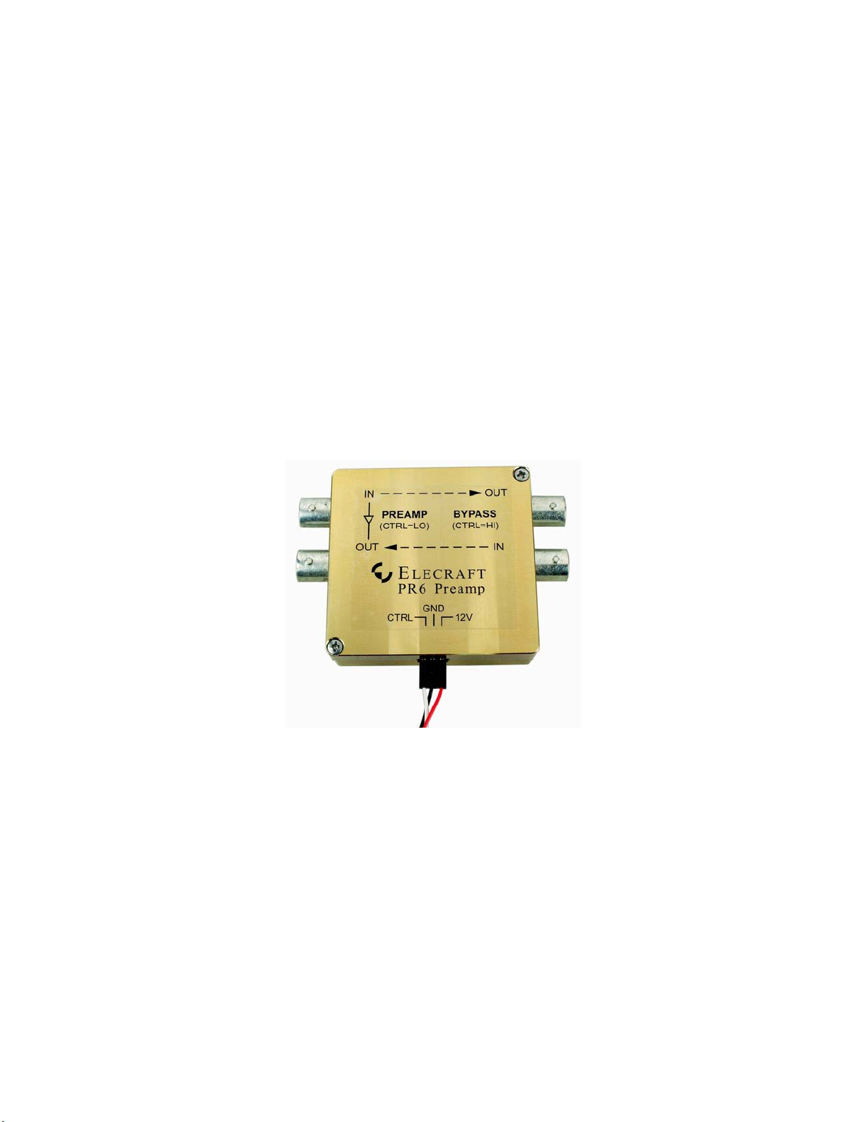
The PR6 is housed in a rugged, custom-machined enclosure.
Figure 1. Elecraft PR6 Low-Noise 6-Meter Receive Preamplifier.
Elecraft • www.elecraft.com • 831-662-8345
Page 2

Specifications
Frequency Coverage: 50 – 54 MHz
Noise Figure: < 0.7 dB, 0.5 dB typical
Gain: 18 dB nominal
IMDDR: >100 dB (when used with an Elecraft K3 transceiver)
Power Requirements: 11 to 14 VDC: 13.8 VDC @ 70 mA nominal
Size: Case: 2-1/4” x 2-5/16” x 3/4” (5.72 x 5.87 x 1.91 cm)
Weight 3 oz (90 grams)
Installation and Operation
Elecraft K3
The BNC connector spacing matches the rear-panel RX ANT connectors so the PR6 may be attached to the
K3 using the supplied male-male BNC connectors as shown in Figure 2. A prewir ed cable is supplied that
connects to the K3 as follows:
Power is taken from the K3 12V jack on the rear panel: red (12V) to the center pin and black
(GND) to the shell. Power to the PR6 will be switched on and off along with K3 using the front
panel POWER button.
The Control (CTRL) input is optional (see below) when the DB-15 connector is attached to the
ACC connector on the K3. The white CTRL wire is connected to the DIGOUT1 signal at pin 11 of
the ACC jack on the K3 rear panel through the DB-15 connector (See Figure 2). If you already
have a cable connected to the K3 ACC port for a transverter or band decoder, remove the DB-15
from the cable and add the wire to pin 11 of the existing connector.
Control (CTRL) Input
When the control (CTRL) is used and jumper P2 is removed (see Figure 3), the K3 may be configured so
that the preamplifier is switched on only when the 6 meter band is selected. Since power is switched off on
other bands, the bypass connections are active and the preamplifier does not draw power. Configure the K3
as follows:
Select the 6 meter band, then set CONFIG: DIGOUT1 ON. Make sure it is OFF for all other
bands. Note: If a KAT3 ATU is installed, the DIGOUT1 setting will be stored per-antenna (in
addition to per-band). Be sure to turn DIGOUT1 ON only for antennas that require the gain
provided by the PR6. You can tap ANT while you're in the DIGOUT1 menu entry, if applicable.
On 6 meters, tap RX ANT to enable the preamplifier.
If the control (CTRL) line is not used and jumper P2 is installed (see Figure 3), the PR6 will be switched
into the circuit when the RX ANT button is pressed. The bypass antenna connections are not available
unless power is removed from the PR6.
Page 2 PR6 6-Meter Receiver Preamplifier Owner’s Manual
Page 3

Other 6-Meter Receivers and Transceivers
The cover label on the PR6 identifies the signal, power and control connections.
The preamplifier is switched into the circuit by applying +12 VDC to the unit if jumper P2 is
installed or, if jumper P2 is removed, by applying +12 VDC and grounding the CTRL input.
Jumper P2 is shown in Figure 3.
If used at a transceiver RF output, limit the RF power passing through the PR6 to 15 watts in
bypass. RF power must not be present when relays switch.
The coaxial lines may carry up to 13.8 VDC as well as RF to power an external device when it is
in bypass mode. Blocking capacitors isolate the preamplifier circuit from the d-c voltage.
Figure 2. PR6 Mounted on Elecraft K3.
PR6 6-Meter Receiver Preamplifier Owner’s Manual Page 3
Page 4

Figure 3. Jumper P2 Location.
Circuit Description
The schematic diagram of the PR6 is shown on the next page.
The Avago ATF34143 low noise PHEMPT was designed for the VHF through low microwave frequency
range. It is capable of providing high gain and exceptionally low noise figure in the 6 meter band.
In the PR6, the input L network and L4 in the source circuit provide a near optimum noise match to the
ATF34143 from the PR6 50 ohm input. R2 is provided to set the drain current and is factory adjusted.
The drain circuit is entirely resistive. The absence of reactive components helps to assure stability. The
zener diode, D2 does not conduct in normal operation because the voltage across it is approximately 4
volts. It is provided as a voltage clamp to assure that the drain voltage does not exceed device ratings
during adjustment of R2.
The remaining circuitry is provided to switch the PR6 in and out of the signal path and DC switching to
provide power and control.
Page 4 PR6 6-Meter Receiver Preamplifier Owner’s Manual
Page 5

PR6 6-Meter Receiver Preamplifier Owner’s Manual Page 5
 Loading...