

Page 1
ELECRAFT PR10 10-Meter Receive Preamplifier
Owner’s Manual
Revision A, October 20, 2011
Copyright © 2011, Elecraft, Inc. All Rights Reserved
Introduction
The PR10 is a high-performance, low-noise 10-meter preamp that can be used with the Elecraft K3 or other
transceivers. It's especially well-suited for the K3, which has exceptional dynamic range, yet can benefit
from additional gain for 10-meter weak signal work. Adding the PR10 typically improves 10-meter MDS
to -143 dBm. The noise figure of the preamp itself is typically 0.5 dB.
The PR10 can be connected directly to the RX ANT IN/OUT jacks on the K3's KXV3 modu le (required),
where it can be switched in automatically by the transceiver when operating on 10 meters. A second pair of
jacks is provided on the opposite side of the PR10 to allow use of the K3's normal RX ANT IN/OUT signal
path when the preamp is not in use.
Power for the PR10 can be obtained from any 11 to 14 VDC supply. When used with a K3, the PR10 can
be powered from the 12 VDC accessory output. It can be strapped permanently ON, or it can be turned
on/off externally from an open-source/open-drain logic signal. In the K3 case, the DIGOUT1 control line
can be used (on the 15-pin ACC jack), since it is stored on a per-band basis.
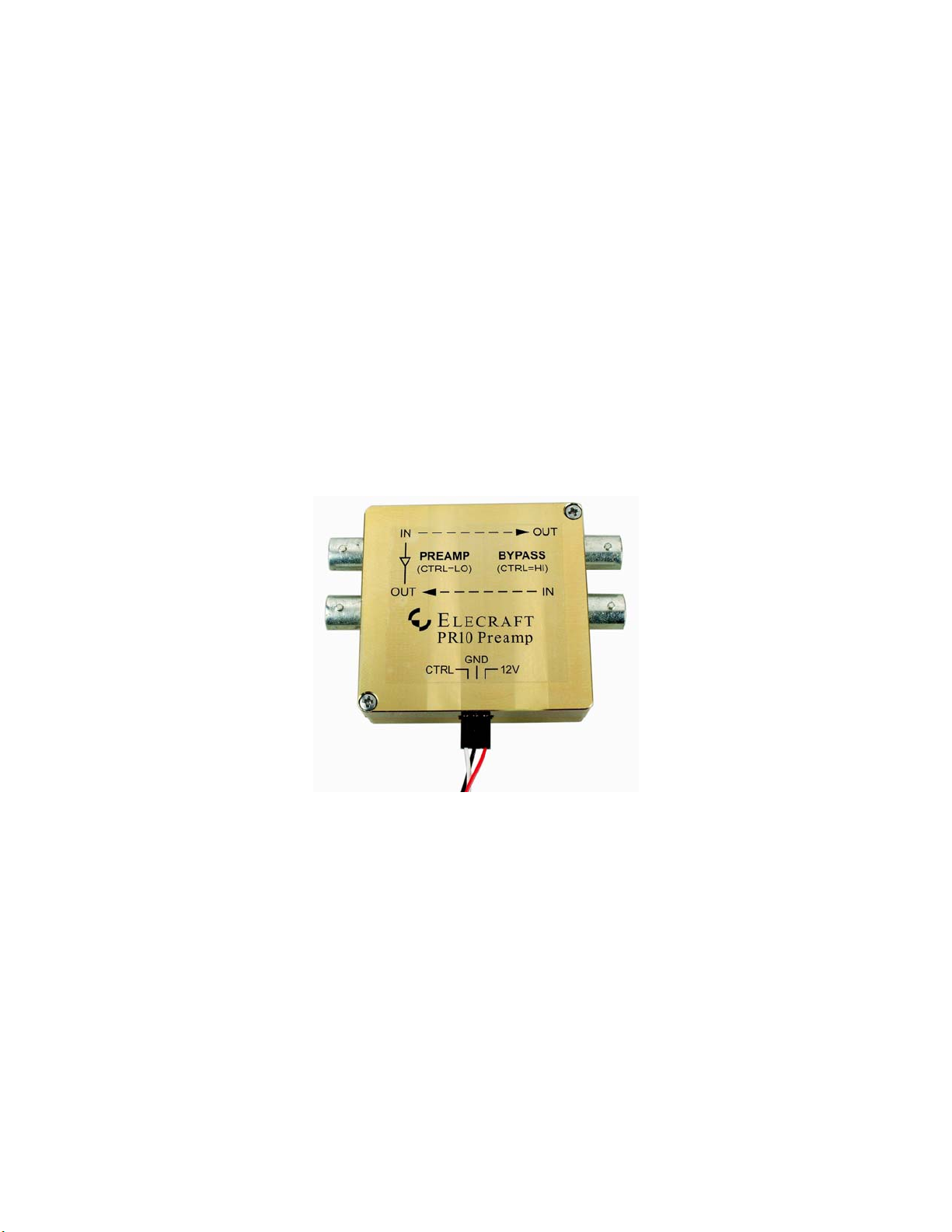
The PR10 is housed in a rugged, custom-machined enclosure.
Figure 1. Elecraft PR10 Low-Noise 10-meter Receive Preamplifier.
Elecraft • www.elecraft.com • 831-763-4211
Page 2

Specifications
Frequency Coverage: 28 – 30 MHz
Noise Figure: < 0.7 dB, 0.5 dB typical
Gain: 18 dB nominal
IMDDR: >100 dB (when used with an Elecraft K3 transceiver)
Power Requirements: 11 to 14 VDC: 13.8 VDC @ 70 mA nominal
Size: Case: 2-1/4” x 2-5/16” x 3/4” (5.72 x 5.87 x 1.91 cm)
Weight 3 oz (90 grams)
Installation and Operation
Elecraft K3
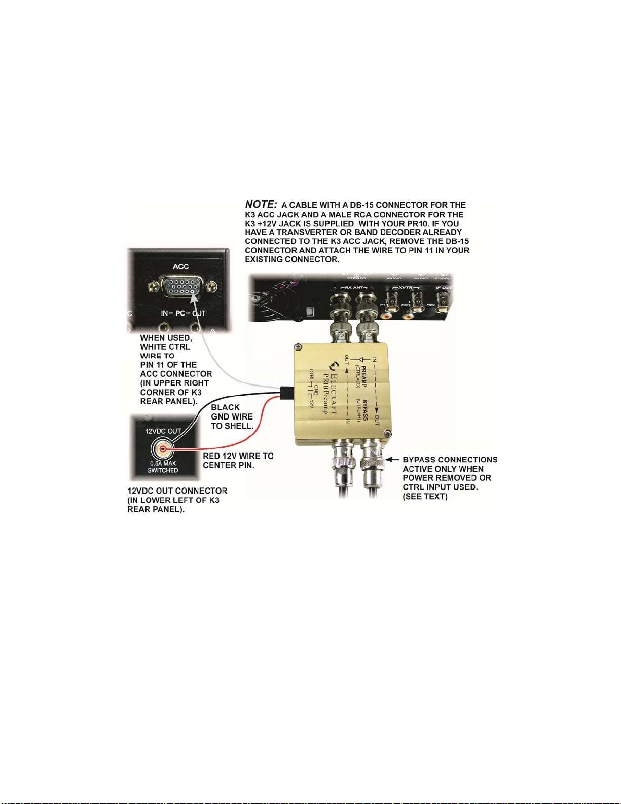
The BNC connector spacing matches the rear-panel RX ANT connectors so the PR10 may be attached to
the K3 using the supplied male-male BNC connectors as shown in Figure 2. A prewired cable is supplied
that connects to the K3 as follows:
Power is taken from the K3 12V jack on the rear panel: red (12V) to the center pin and black
(GND) to the shell. Power to the PR10 will be switched on and off along with K3 using the front
panel POWER button.
The Control (CTRL) input is optional (see below) when the DB-15 connector is attached to the
ACC connector on the K3. The white CTRL wire is connected to the DIGOUT1 signal at pin 11 of
the ACC jack on the K3 rear panel through the DB-15 connector (See Figure 2). If you already
have a cable connected to the K3 ACC port for a transverter or band decoder, remove the DB-15
from the cable and add the wire to pin 11 of the existing connector.
Control (CTRL) Input
When the control (CTRL) is used and jumper P2 is removed (see Figure 3), the K3 may be configured so
that the preamplifier is switched on only when the 10 meter band is selected. Since power is switched off
on other bands, the bypass connections are active and the preamplifier does not draw power. Configure the
K3 as follows:
Select the 10 meter band and then set CONFIG: DIGOUT1 ON. Make sure it is OFF for all other
bands. Note: If a KAT3 ATU is installed, the DIGOUT1 setting will be stored per-antenna (in
addition to per-band). Be sure to turn DIGOUT1 ON only for antennas that require the gain
provided by the PR10. You can tap ANT while you're in the DIGOUT1 menu entry, if applicable.
On 10 meters, tap RX ANT to enable the preamplifier.
If the control (CTRL) line is not used and jumper P2 is installed (see Figure 3), the PR10 will be switched
into the circuit when the RX ANT button is pressed. The bypass antenna connections are not available
unless power is removed from the PR10.
Page 2 PR10 10-Meter Receiver Preamplifier Owner’s Manual
Page 3
Other 10-meter Receivers and Transceivers
The cover label on the PR10 identifies the signal, power and control connections.
The preamplifier is switched into the circuit by applying +12 VDC to the unit if jumper P2 is
installed or, if jumper P2 is removed, by applying +12 VDC and grounding the CTRL input.
Jumper P2 is shown in Figure 3.
If used at a transceiver RF output, limit the RF power passing through the PR10 to 15 watts in
bypass. RF power must not be present when relays switch.
The coaxial lines may carry up to 13.8 VDC as well as RF to power an external device when it is
in bypass mode. Blocking capacitors isolate the preamplifier circuit from the d-c voltage.
Figure 2. PR10 Mounted on Elecraft K3.
PR10 10-meter Receiver Preamplifier Owner’s Manual Page 3
Page 4

Figure 3. Jumper P2 Location.
Circuit Description
The schematic diagram of the PR10 is shown on the next page.
The Avago ATF34143 low noise PHEMPT was designed for the VHF through low microwave frequency
range. It is capable of providing high gain and exceptionally low noise figure in the 10 meter band.
In the PR10, the input L network and L4 in the source circuit provide a near optimum noise match to the
ATF34143 from the PR10 50 ohm input. R2 is provided to set the drain current and is factory adjusted.
The drain circuit is entirely resistive. The absence of reactive components helps to assure stability. The
zener diode, D2 does not conduct in normal operation because the voltage across it is approximately 4
volts. It is provided as a voltage clamp to assure that the drain voltage does not exceed device ratings
during adjustment of R2.
The remaining circuitry is provided to switch the PR10 in and out of the signal path and DC switching to
provide power and control.
Page 4 PR10 10-Meter Receiver Preamplifier Owner’s Manual
Page 5

PR10 10-meter Receiver Preamplifier Owner’s Manual Page 5
Page 6

Customer Service and Support
Technical Assistance
You can send e-mail to k3support@elecraft.com and we will respond quickly – typically the same day
Monday through Friday. If you need replacement parts, send an e-mail to parts@elecraft.com. Telephone
assistance is available from 9 A.M. to 5 P.M. Pacific time (weekdays only) at 831-763-4211. Please use email rather than calling when possible since this gives us a written record of the details of your problem and
allows us to handle a larger number of requests each day.
Repair / Alignment Service
If necessary, you may return your Elecraft product to us for repair or alignment. (Note: We offer unlimited
email and phone support, so please try that route first as we can usually help you find the problem quickly.)
IMPORTANT: You must contact Elecraft before mailing your product to obtain
authorization for the return, what address to ship it to and current information on repair fees and
turnaround times. (Frequently we can determine the cause of your problem and save you the
trouble of shipping it back to us.) Our repair location is different from our factory location in
Aptos. We will give you the address to ship your kit to at the time of repair authorization.
Packages shipped to Aptos without authorization will incur an additional shipping charge for
reshipment from Aptos to our repair depot.
Page 6 PR10 10-Meter Receiver Preamplifier Owner’s Manual
Page 7

Elecraft 1-Year Limited Warranty
This warranty is effective as of the date of first consumer purchase (or if shipped from the factory,
the date the product is shipped to the customer). It covers both our kits and fully assembled products.
For kits, before requesting warranty service, you should fully complete the assembly, carefully
following all instructions in the manual.
Who is covered: This warranty covers the original owner of the Elecraft product as disclosed to
Elecraft at the time of order. Elecraft products transferred by the purchaser to a third party, either by
sale, gift, or other method, who is not disclosed to Elecraft at the time of original order, are not
covered by this warranty. If the Elecraft product is being bought indirectly for a third party, the third
party’s name and address must be provided at time of order to ensure warranty coverage.
What is covered: During the first year after date of purchase, Elecraft will replace defective or
missing parts free of charge (post-paid). We will also correct any malfunction to kits or assembled
units caused by defective parts and materials. Purchaser pays inbound shipping to us for warranty
repair; we pay shipping to return the repaired equipment to you by UPS ground service or equivalent
to the continental USA and Canada. For Alaska, Hawaii, and other destinations outside the U.S. and
Canada, actual return shipping cost is paid by the owner.
What is not covered: This warranty does not cover correction of kit assembly errors. It also does not
cover misalignment; repair of damage caused by misuse, negligence, or builder modifications; or any
performance malfunctions involving non-Elecraft accessory equipment. The use of acid-core solder,
water-soluble flux solder, or any corrosive or conductive flux or solv ent will void this warranty in its
entirety. Also not covered is reimbursement for loss of use, inconvenience, customer assembly or
alignment time, or cost of unauthorized service.
Limitation of incidental or consequential damages: This warranty does not extend to non-Elecraft
equipment or components used in conjunction with our products. Any such repair or replacement is
the responsibility of the customer. Elecraft will not be liable for any special, indirect, incidental or
consequential damages, including but not limited to any loss of business or profits.
PR10 10-meter Receiver Preamplifier Owner’s Manual Page 7
 Loading...