

Page 1

ELECRAFT
P3
H
IGH-PERFORMANCE
P
ANADAPTER
P3SVGA OPTION
INSTALLATION
INSTRUCTIONS
Revision D, September 30, 2012
Copyright © 2012, Elecraft, Inc.
All Rights Reserved
AND OPERATING
Page 2

Contents
Introduction ...................................................................................................................................... 3
Customer Service and Support .................................................................................................................. 4
Operation ......................................................................................................................................... 5
Connections ............................................................................................................................................... 5
Firmware ................................................................................................................................................... 5
Display Setup ............................................................................................................................................ 5
Data Terminal Setup .................................................................................................................................. 7
Transmit Setup .......................................................................................................................................... 8
Text Message Entry ................................................................................................................................... 9
Beacon Mode .......................................................................................................................................... 10
Using Macros .......................................................................................................................................... 11
Installing the P3SVGA Option Board ........................................................................................... 12
Preventing Electrostatic Discharge Damage ........................................................................................... 12
Tools Required ........................................................................................................................................ 12
Parts Included .......................................................................................................................................... 13
Installation Procedure .............................................................................................................................. 14
Elecraftmanualswithcolorimagesmaybedownloadedfromwww.elecraft.com
2
.
Page 3
Introduction
The P3SVGA Super Video Graphics Array option adds wide screen display capability to the P3 with enhanced
data terminal operations that permits sending text from a keyboard attached to the P3, storing messages in
memory that may be recalled with a simple keystroke, and transmitting a stored message at regular intervals.
The P3SVGA features a dedicated, high-speed Fast Fourier Transform (FFT) processor that performs a 2048
point FFT in parallel with the P3’s existing processor for a much higher frequency resolution per dot on the
larger screen. The P3SVGA also includes an interface for a future USB option that will permit direct digital
mode operation via the K3 and P3 with data display on the P3 and P3SVGA screens.
The P3SVGA adds three connectors to the P3 rear panel:
the
KEYBOARD and EXT. DISPLAY connectors are active at this time. The AUX DATA connector is reserved for
future use.
The P3SVGA supports the following video resolutions:
1024 X 768
1280 X 1024
1440 X 900
1920 X 1080
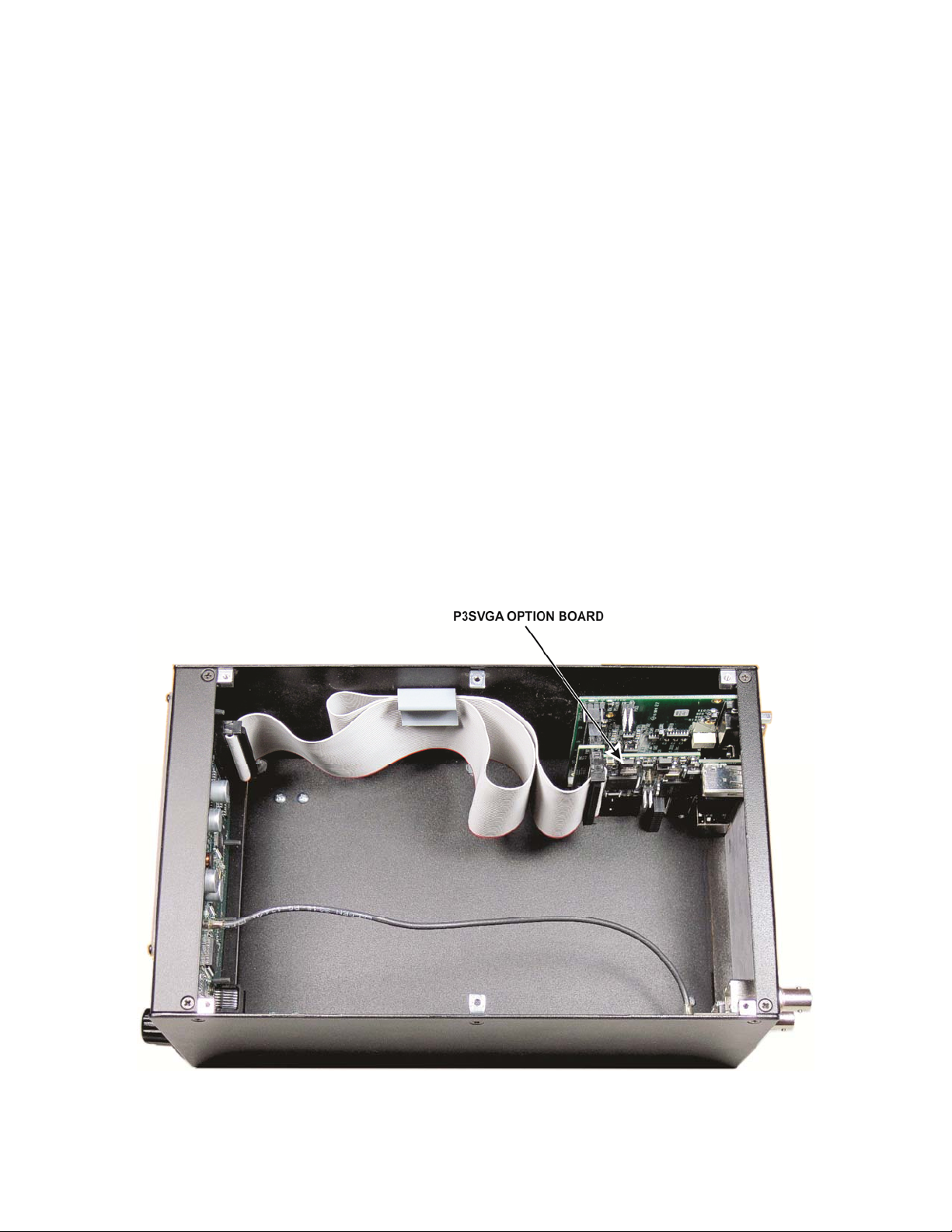
The P3SVGA is a single-plug in board (see Figure 1). Only a few basic hand tools are needed (see pg 12) to
perform the installation. No soldering or wiring is required.
Turn to page 12 to install the P3SVGA option in your P3.
KEYBOARD, EXT. DISPLAY and AUX DATA. Only
For faster screen updates when using fixed tune
mode, we recommend setting the P3SVGA
resolution to 1440 x 900 or less. Note that
1440 x 900 will display correctly on
1920 x 1080 monitors.
Figure 1. P3SVGA Board Installed (P3 Top Cover Removed).
3
Page 4

Customer Service and Support
Technical Assistance
You can send e-mail to k3support@elecraft.com and we will respond quickly – typically the same day
Monday through Friday. If you need replacement parts, send an e-mail to parts@elecraft.com
. Telephone
assistance is available from 9 A.M. to 5 P.M. Pacific time (weekdays only) at 831-763-4211. Please use e-mail
rather than calling when possible since this gives us a written record of the details of your problem and allows us
to handle a larger number of requests each day.
Repair / Alignment Service
If necessary, you may return your Elecraft product to us for repair or alignment. (Note: We offer unlimited email
and phone support, so please try that route first as we can usually help you find the problem quickly.)
IMPORTANT: You must contact Elecraft before mailing your product to obtain authorization for the
return, what address to ship it to and current information on repair fees and turnaround times. (Frequently we
can determine the cause of your problem and save you the trouble of shipping it back to us.) Our repair location
is different from our factory location in Aptos. We will give you the address to ship your kit to at the time of
repair authorization. Packages shipped to Aptos without authorization will incur an additional shipping charge
for reshipment from Aptos to our repair depot
.
Elecraft 1-Year Limited Warranty
This warranty is effective as of the date of first consumer purchase (or if shipped from the factory, the date the
product is shipped to the customer). It covers both our kits and fully assembled products. For kits, before requesting
warranty service, you should fully complete the assembly, carefully following all instructions in the manual.
Who is covered: This warranty covers the original owner of the Elecraft product as disclosed to Elecraft at the time
of order. Elecraft products transferred by the purchaser to a third party, either by sale, gift, or other method, who is
not disclosed to Elecraft at the time of original order, are not covered by this warranty. If the Elecraft product is being
bought indirectly for a third party, the third party’s name and address must be provided at time of order to ensure
warranty coverage.
What is covered: During the first year after date of purchase, Elecraft will replace defective or missing parts free of
charge (post-paid). We will also correct any malfunction to k its or assembled units caused by defective parts and
materials. Purchaser pays inbound shipping to us for warranty repair; we pay shipping to return the repaired
equipment to you by UPS ground service or equivalent to the continental USA and Canada. For Alaska, Hawaii, and
other destinations outside the U.S. and Canada, actual return shipping cost is paid by the owner.
What is not covered: This warranty does not cover correction of kit assembly errors. It also does not cover
misalignment; repair of damage caused by misuse, negligence, battery leakage or corrosion, or builder modifications;
or any performance malfunctions involving non-Elecraft accessory equipment. The use of acid-core solder, watersoluble flux solder, or any corrosive or conductive flux or so lvent will void this warranty in its entirety. Also not
covered is reimbursement for loss of use, inconvenience, customer assembly or alignment time, or cost of
unauthorized service.
Limitation of incidental or consequential damages: This warranty does not extend to non-Elecraft equipment or
components used in conjunction with our products. Any such repair or replacement is the responsibility of the
customer. Elecraft will not be liable for any special, indirect, incidental or consequential damages, including but not
limited to any loss of business or profits.
4
Page 5

Operation
Connections
Power
Connect the P3 directly to a 10 to 15 VDC power source capable of providing at least 700 mA. You may use the
K3
12VDC OUT power connector if it is labeled 1.0 A MAX SWITCHED. Older K3’s were limited to 500 mA,
which is adequate to power the P3 without the SVGA, but not the P3 with the SVGA option enabled. If your
K3’s
12VDC OUT is limited to 500 mA, you can install, or have Elecraft install, the K3 12V Output Current
Modification kit to increase the current available to 1 Ampere. Order the K312MDKT.
Monitor
Connect your SVGA monitor to the EXT. DISPLAY connector on the P3 rear panel.
Keyboard
Most PC keyboards using an USB connection will work with the P3 SVGA. Apple keyboards are not supported
at this time. Plug the keyboard into the
KEYBOARD connector on the P3 rear panel.
Firmware
Your P3 must have firmware version 1.20 or later and the SVGA must have firmware version 1.10 or later
installed. To check the firmware versions, turn the P3 on, tap
Rev. The current P3 firmware revision is shown on the P3’s internal screen. Turn the SELECT knob to SVGA
, and then tap it again to enter the SVGA sub menu. Turn the SELECT knob to SVGA FW and tap the
menu
knob again to display the revision of the SVGA firmware installed.
If needed, see Firmware Upgrades in your P3 Owner’s Manual for information on how upgrade your firmware.
MENU and then turn the SELECT knob to FW
Display Setup
Tap MENU and then turn the SELECT knob to SVGA menu. Tap the SELECT knob enter the sub-menu.
SVGA Display On/Off
The external display is activated automatically when the P3 is turned on. You can turn the external display off
or on from the SVGA sub-menu. In the SVGA sub-menu, turn the
the
SELECT knob again to toggle between SVGA on and SVGA off.
SVGA Firmware Version
In the SVGA sub-menu, turn the SELECT knob to SVGA FW and then tap the SELECT knob again to
display the installed SVGA firmware version.
SELECT knob to SVGA en and then tap
Set Resolution
In the SVGA sub-menu, turn the SELECT knob to SVGA res and then tap the SELECT knob again. Turn
the
SELECT knob to select the desired resolution.
5
Page 6
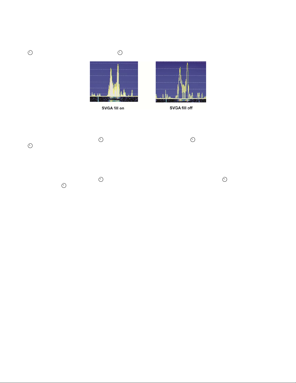
Spectrum Display Fill
This setting fills the space below the spectrum line or leaves it open (see Figure 2). It does not have any effect
on the waterfall display or the spectrum display on the P3’s internal screen. In the SVGA sub-menu, turn the
SELECT knob to SVGA fill then tap the SELECT knob to toggle the fill on or off.
Figure 2. SVGA Spectrum Display Fill.
SVGA Font Size
In the SVGA sub-menu, turn the SELECT knob to SVGA font and tap the SELECT knob again. Turn the
SELECT knob to change the font size. Three sizes are available, 0, 1 and 2, shown in the upper left of the
internal P3 display. The change will appear after a brief interval on the SVGA monitor so you can see the effect
of the change without leaving the menu.
SVGA Waterfall Color Bias
In the SVGA sub-menu, turn the SELECT knob to SVGA waterfall color bias and tap the SELECT knob
again. Turn the
The change will appear immediately on the SVGA monitor waterfall display so you can see the effect without
leaving the menu.
SELECT knob to change the bias value (shown in upper left corner of the P3 internal display).
6
Page 7

Data Terminal Setup
Data terminal mode adds three windows at the bottom of the SVGA monitor: one for received data, one for
transmitted data and a status bar (see Figure 3). These windows occupy part of the area used by the waterfall
display. The height of the status bar is fixed. The sizes of the receive and transmit data windows, and the sizes
of the fonts used for them, are variable using the setup menu as described below.
Figure 3. SVGA Display with Data Terminal Mode Enabled.
Adjusting the Receive and Transmit Windows and Font Sizes
The area occupied by the receive and transmit data windows depends upon the font size and monitor resolution
used. Since the data windows occupy part of the space normally available to the waterfall display, you may need
to increase the size of the waterfall display to provide room for them.
If the transmit data window size is set to zero, data transmission is disabled, the transmit data
window will disappear and the keyboard becomes inactive.
To set the window and font sizes, tap
SELECT knob enter the sub-menu. Turn the SELECT knob to the desired parameter tap the SELECT knob
again. Turn the
SVGA WinR Sets the size of the receive data window (in lines).
SVGA WinT Sets the size of the transmit data window (in lines).
SVGA fntD Sets the size of the font. 0 is the smallest, 3 is the largest.
SELECT knob to change the parameter:
MENU and then turn the SELECT knob to SVGA menu. Tap the
Decoding Text
The decoding of signals takes place in the K3. See your K3 Owner’s manual for details about how to configure
the K3 to decode text in CW and each of the data modes.
7
Page 8

Transmit Setup
Using the Keyboard
An asterisk on the SVGA display data line (see Figure 3) indicates that the keyboard is connected and active.
Keyboard shortcuts are listed below. (Hyphenated keys must be pressed at the same time.)
Keyboard Shortcuts
KEYS FUNCTION
Ctrl-H
Opens help screen except when editing messages or macros. Press any key to exit.
Backspace
Ctrl-Backspace
Ctrl-Alt-M
Ctrl-Alt-T
Ctrl-Alt-S
Ctrl-Alt-B
Esc
Scroll Lock
Ctrl-R
Ctrl-T
Ctrl-C
Scroll Lock
|
Deletes character to the left.
Deletes word to the left.
Opens K3 macro entry pop-up window.
Opens text messages pop-up window.
Opens setup menu.
Starts beacon transmit.
Switches K3 to receive and clears the transmit data window.
Freezes receive data window. Press again to resume.
Switches the K3 to receive. If the K3 is transmitting data or CW, transmission
pauses.
Resume transmission
Clears the transmit and receive data windows.
Freezes the receive data window.
When inserted into a text message, causes the K3 to revert to receive mode at the
end of the message
NOTE: On-screen menus use the carat,
(upper case 6), to denote the Control (Ctrl) key.
^
Setup Options
The transmit mode options and text color parameters that you can set are listed below. Press Ctrl-Alt-S to open
the setup menu on the SVGA screen. This screen will cover the transmit data window and status bar
temporarily. Use the up/down arrows on the keyboard to select a parameter and the left/right arrows to change
the parameter. Pressing
menu. The parameters are saved in non-volatile memory so they will be retained after power has been turned off
and then on again.
Transmit Mode: CR, ^T, VOX
Allows you to control when text entered on the keyboard is sent:
CR: The K3 will start transmitting the text only after the
^T: The K3 will start transmitting the text only after
VOX: The K3 will transmit each character as it is typed on the keyboard.
NOTE: Pressing
transmission. In ^T mode, press
clears any unsent text.
Ctrl-arrow changes the values in larger steps. Press Esc to save the changes and close the
Enter key is pressed.
Ctrl-T is pressed.
Ctrl-R will interrupt a transmission. In CR or VOX modes, press Enter to restart a
Ctrl-T to restart the transmission. Pressing Esc stops the transmission and
8
Page 9

Transmit Timeout: 0 to 90,000 ms (0 to 90 seconds) in 200 ms (0.2 second) increments.
The length of time an idle signal will be transmitted in PSK or RTTY modes after the last character is sent. Any
character entered on the keyboard during this time will be sent and the timeout period will start over. Pressing
|
(the vertical bar) on the keyboard will terminate the delay and return the K3 to receive mode immediately.
Transmitted Text Color: 1 to 50
The color of the text in the transmit data window changes as each character is sent. Use this parameter to choose
the color of the characters after they have been sent.
Tx Text Color: 1 to 50
Use this parameter to choose the color of the unsent characters in the transmit data window.
Rx Text Color: 1 to 50
Use this parameter to choose the color of the text shown in the receive data window.
Beacon Text Mem# and Beacon Interval
See Beacon Mode on pg 10.
Text Message Entry
There are 50 text message memory locations available that can be used in CW, RTTY or PSK modes. Each
location can store up to 124 characters (including spaces). These messages are stored in non-volatile memory so
they will not be lost when power is cycled. Create a text message as follows:
Press
Ctrl-Alt-T to enter the text message window. The window opens on top of the data and status
windows. Press the up and down arrows to find an available (empty) message location (indicated by an
<empty> key assignment), or you can select a message that is no longer needed. Figure 4 shows that
memory location 1 is available.
Figure 4. Empty Text Message Location.
Press
Enter to use the selected memory location.
Figure 5. Assigning a Recall Key.
Press the key(s) that you want to use to recall this message. In the example shown in Figure 6, the
key combination was assigned to the message. If the name of the key does not appear when it is
B
pressed, it has already been assigned to another message. You must choose a different key.
ALT-
9
Page 10

Enter the text of the message. In this example the message is “Rig is an Elecraft K3 with P3/SVGA.”
Correct errors using the
Backspace, Ctrl-Backspace or Ctrl-C keys as needed.
Figure 6. Editing a Message.
When finished, press
message. When finished, press
To send a message, press the assigned key to recover any message. In this example, pressing
Enter to save the message and prepare to select the next location and enter another
Esc to exit.
Alt-B
transfers the test message to the transmit text window and begins transmission.
To edit a message, select it and return to the key assignment (Figure 5) or editing (Figure 6) screens and
make the desired changes. To erase a message select it and, at the key assignment window, press
Ctrl-C.
Beacon Mode
Beacon mode transmits a text message repeatedly with a time interval between each transmission. The message
is stored in memory in advance. You choose the message and the time interval desired. The message will be
transmitted using the mode selected at the K3: CW, RTTY, or PSK.
Set up a message to be sent as a beacon as follows:
Store your message to be sent (see Text Message Entry, pg 9). You can use any memory location. Press
Esc when you are done entering the message. Note that the key assigned to the message when you
stored it in memory is not used when transmitting it in beacon mode. The key is used only when
manually choosing a message to send.
Press
Press the down arrow key to select
Use the right/left arrows to enter the memory location where the beacon message is stored. Right arrow
Ctrl-Alt-S to enter the setup screen.
Beacon Text Mem #.
increments the numbers by 1 and left arrow decrements the number by 1.
steps of 10.
Ctrl-Arrow moves the count in
Press the down arrow to
Beacon Interval.
Press the right/left arrows to select the desired interval between transmissions. You can select any
interval between 0 and 3600 seconds (1 hour). Right arrow increments the numbers by 1 and left arrow
decrements the number by 1.
Press
Press
Esc to exit the setup screen.
Ctrl-Alt-B to start the beacon transmission. A flashing letter B will appear in the lower right corner
Ctrl-Arrow moves the count in steps of 10.
of the status line.
If a station answers, you may:
Press
Esc. That stops the transmission and clears the transmit window. You can then type a reply that
will be transmitted immediately or when you enter CR or ^T, depending upon the transmit mode you
have selected (see Transmit Mode, pg 8 ).
Start typing your reply. This automatically cancels further beacon transmission but does not interrupt
the beacon message while it is being transmitted. Your reply will be transmitted immediately after the
beacon message. You do not need to initiate transmission.
10
Page 11

Using Macros
Macros are used to automate a sequence of control setting and button pushes on the K3 so that they may be
accomplished with a single entry on the keyboard. For example you may want to create macros to shift the K3
into a particular mode on a specific frequency or band by a simple one or two key entry on the keyboard. You
can create and enter up to 50 macros of up to 124 characters each. They are stored in non-volatile memory so
they will not be lost when power is cycled. These memory locations are independent of the message memories.
You can store 50 messages and 50 macros at the same time.
Entering Macros
Press Ctrl-Alt-M to open the macro entry window. The process of entering the various windows, assigning a key
used to recall the macro and editing macros is identical to that used for text messages. See Text Message Entry,
above. Note that to enter the text message entry window you pressed
enter the macro entry window.
Sample Macro:
Assign a macro memory to the F1 key (see Figure 5) and enter and save the following macro (see Figure 6):
FA00014970000;MD6;FA00014070000;DT3
Now pressing F1 on the keyboard will send the above macro to the K3 setting VFO A to 14.070 and the mode to
DATA, PSK31.
Ctrl-Alt-T but you must press Ctrl-Alt-M to
NOTE: When creating a macro, pressing
into the macro in the form of an FA command. For example, if VFO A is set to 7.123 and
while entering the macro,
FA00007123000; will be inserted into the macro string.
^F will place the K3’s current frequency (including RIT)
^F is pressed
For more information about writing macros, refer to the K3 Programmer’s Reference available on the Elecraft
web site at www.elecraft.com
or the K3 Utility help screens.
11
Page 12

Installing the P3SVGA Option Board
Preventing Electrostatic Discharge Damage
We strongly recommend you take the following anti-static precautions (listed in order of importance) to avoid
trouble:
Leave ESD-sensitive parts in their anti-static packaging until you install them. The packaging may be a
special plastic bag or the component’s leads may be inserted in conductive foam. Parts which are
especially ESD-sensitive are identified in the parts list and in the assembly procedures.
Wear a conductive wrist strap with a series 1-megohm resistor. If you do not have a wrist strap, touch a
ground briefly before touching any sensitive parts to discharge your body. Do this frequently while you
are working. You can collect a destructive static charge on your body just sitting at the work bench. DO
NOT attach a ground directly to yourself as this poses a serious shock hazard.
Use a grounded anti-static mat on your work bench.
If you choose to use a soldering iron to work on your P3 for any reason, be sure your iron has an ESD-
safe grounded tip tied to the same common ground used by your mat or wrist strap.
Tools Required
1. #1 size Phillips screwdriver. To avoid damaging screws and nuts, a power screwdriver is not
recommended.
2. Pliers or wrenches for installing 1/4” (6.4mm) nuts 3/16” (4.8 mm) jack screw nuts.
The following tools are strongly recommended:
1. ESD wrist strap.
2. Static dissipating work pad.
12
Page 13

Parts Included
The following parts should be included in your kit. Check to ensure you have them all. If any parts are damaged
or missing, contact Elecraft for replacements (see Customer Service and Support, pg 4).
ILLUSTRATION DESCRIPTION QTY.
P3SVGA Circuit Board Assembly
1 E850482
ESD Sensitive.
ELECRAFT
PART NO.
Jackscrew Nut, 4-40 (may be mounted on
the Circuit Board Assembly Connector)
Lock Washer, Inside Tooth, #4 (may be
mounted on the Circuit Board Assembly
Connector)
Power cord assembly (used to connect the
P3 directly to a 10 to 15 VDC power supply).
NOTE: Do not attempt to power your P3 from
the K3’s 12V outlet unless it is labeled 1.0A
Max. See Power on pg 5 for details.
2 E700078
2 E700010
1 E850427
13
Page 14

Installation Procedure
Disconnect power and all cables from your P3.
Remove the six screws to free the top cover (Figure 7 ) and lift the cover off. There is a slot at
one end that you can use to lift the cover once it is free.
Whenever you remove screws from a panel, if one screw seems too tight to loosen
without damaging it, first loosen the other screws then try again. Sometimes one
screw binds in its hole when the other screws are tightened.
Figure 7. Preparing the P3 to Install the P3SVGA Board.
CAUTION:
before touching components or circuit boards inside the P3. See Preventing
Electrostatic Discharge Damage on page 12 for more information.
Remove the four jack screw nuts and lock washers to free the I/O board (Figure 7 )
Touch an unpainted metal ground or wear a grounded wrist strap
14
Page 15

Lift the I/O board out of the P3 and unplug the ribbon cable (Figure 7 ). Take care not to damage
the board. Hold the board while working the connector side to side to “walk” it off of the pins as shown in
Figure 8.
Figure 8. Unplugging the Ribbon Cable from the I/O Board.
Unplug the TMP coaxial cable from the RF board (Figure 7 ). This is a friction-fit connector. Do
not pull on the black coaxial cable. Grip and pull only on the metal connector.
Remove the four screws holding the rear panel in place (Figure 7 ) and lift the rear panel off of
the P3.
Remove and reverse the mounting hardware for both rear feet as shown in Figure 7 ). Install the
hardware as shown in Figure 9.
INSTALLATION HINT: Put the washer and screw in the foot opening and press your finger over the
opening until the threads on the nut are caught by the screw. It may help to turn the unit over so gravity
helps. Once the nut is started pull the foot away from the bottom cover while tightening the screw. The
friction of the washer against the bushing inside the foot will keep the nut from turning as you tighten.
Figure 9. Reversing the Foot Hardware.
15
Page 16

Remove the plastic covering from the AUX. DATA, EXT. DISPLAY and KEYBOARD openings on the
rear cover, but leave the covering over the
SENSOR opening (see Figure 10). The plastic cover will snap
apart at the score mark as you bend it away from the panel.
Figure 10. Removing Hole Covers.
Mount the P3SVGA board on the I/O board as shown in Figure 11. The connector on the P3SVGA
board mates with the connector on the I/O board that originally received the ribbon cable. Be sure the
connectors are aligned so that all pins engage. To avoid over-stressing the boards, place the I/O
board on a firm surface. You may need to rock the P3SVGA board slightly while pressing down to
“walk” the pins into the connector like you did when removing the ribbon cable earlier.
Figure 11. Mating the I/O and P3SVGA Boards.
16
Page 17

Connect the ribbon cable to the P102 on the P3SVGA board as shown in Figure 12. Place the boards
on a firm surface to avoid over-stressing them. Be certain that:
1. The connector is aligned so that that it covers all of both rows of pins.
2. The ribbon cable is oriented so that the red wire is at the pin 1end of the connector as
shown. Your ribbon cable may exit the connector toward the board instead of away from it
as shown here. That is not a problem as long as you orient it to place the red wire at the pin
1 end as shown.
Figure 12. Connecting the Ribbon Cable to the P3SVGA and I/O Boards.
Mount the boards on the rear panel as shown in Figure 13. Start all of the jack screw nuts before
tightening them. Do not over-torque them. It is possible to twist the head off of the threaded section,
especially if you use a wrench.
Figure 13. Mounting Boards in Rear Panel.
17
Page 18

Replace the rear panel assembly on the P3 as shown in Figure 14. Tilt the assembly so the P3SVGA
board does not strike the screw head for the rear foot. The screw head fits in a notch on the P3SVGA
board. Secure the rear panel assembly with the screws you removed earlier (Figure 7
Figure 14. Replacing the Rear Panel on the P3.
).
Reconnect the TMP cable to the rear panel RF board (Figure 7 ).
Replace ribbon cable in the clip on the side panel (Figure 7 ). It is important that the excess cable
not be allowed to float freely in the P3 where it may be close to the RF board to avoid digital interference
on the P3 display.
Replace the top cover on the P3 with the notch to the rear using the screws you removed earlier:
REPLACE ALL THE SCREWS!
The P3's chassis strength depends upon all the screws being in place. Be sure to
replace all the screws and verify they are tight, but do not over-torque the screws.
That completes the installation of the P3SVGA option in your P3. Operating
instructions are on pg 5.
18
 Loading...