

Page 1

ELECRAFT
P3
H
IGH-PERFORMANCE
P
ANADAPTER
OWNER’S MANUAL
Revision D, December 5, 2013
Copyright © 2013, Elecraft, Inc.
All Rights Reserved
Page 2

Contents
NOTE: IF YOU PURCHASED YOUR P3 AS A KIT, GO DIRECTLY TO KIT ASSEMBLY
INSTRUCTIONS ON PAGE 43 TO ASSEMBLE YOUR P3.
Key to Symbols and Text Styles ...................... 3
Quick-Start Guide ............................................ 4
Introduction ...................................................... 7
P3 Features .......................................................... 7
P3SVGA Option .................................................. 7
Specifications ...................................................... 8
Customer Service and Support ............................ 9
Front Panel ..................................................... 10
Control Groups .................................................. 10
Display .............................................................. 11
Primary Controls ............................................... 11
Menu ................................................................. 12
Programmable Function Keys ........................... 12
Rear Panel Connectors ................................... 13
Basic Operation ............................................. 14
Using Tap/Hold Switches ................................. 14
Initial Power-Up ................................................ 14
Configuring the Display .................................... 14
Using the Menu ................................................. 14
Programmable Functions .................................. 15
Adjusting the Frequencies Displayed ................ 15
Using Markers ................................................... 16
Waterfall Markers ............................................. 16
Using Cursors .................................................... 16
How to Set Up and Interpret the P3 Display . 18
Spectrum Display .............................................. 18
Waterfall Display .............................................. 19
Averaging and Peak Hold ................................. 19
Span ................................................................... 19
Fixed-tune mode ................................................ 19
Typical Spectra .................................................. 20
Advanced Operating Features ........................ 22
Basic P3 ............................................................ 22
P3SVGA Option ............................................... 23
Firmware Upgrades ........................................ 29
Checking your Firmware Revision ................... 29
P3 Firmware Self-Test ...................................... 29
Forcing a Firmware Download ......................... 29
Updating K3 Firmware ..................................... 29
Configuration ................................................. 30
Calibration Procedures ................................... 31
Frequency Calibration ...................................... 31
Amplitude Calibration ...................................... 31
Amplitude Calibration for Transverters ............ 32
Menu Functions ............................................. 33
Basic P3 Menu .................................................. 33
P3SVGA Option Menu ..................................... 35
Troubleshooting ............................................. 36
Parameter Initialization .................................. 36
Theory of Operation ....................................... 37
Parts List ........................................................ 38
P3 Sheet Metal Box - E850435 ....................... 38
P3 Misc Bag - E850433 ................................... 39
P3 PCB Box – E850436 ................................... 41
P3SVGA Parts .................................................. 42
Kit Assembly Instructions ............................. 43
Preventing Electrostatic Discharge Damage ..... 43
Tools Required ................................................. 44
Assembly Procedure ......................................... 44
Servicing the P3 ............................................. 59
Accessing the PC Boards .................................. 59
Cleaning the LCD Bezel ................................... 59
Replacing the LCD Display .............................. 60
i
Elecraft manuals with color images may be downloaded from
www.elecraft.com
2
.
Page 3
Key to Symbols and Text Styles
AVERAGE
MENU:Font
-100
DISPLAY
SELECT
QSY
UNDO QSY
Important – read carefully
Operating tip
Characters displayed on the LCD screen
Tap switch function (labeled above a switch)
Hold switch function (labeled below a switch; hold for 1/2 sec. to activate)
Rotary control
Tap switch function of rotary control (labeled above the knob)
Hold switch function of rotary control (hold for 1/2 sec.)
Typical menu entry
3
Page 4
Quick-Start Guide
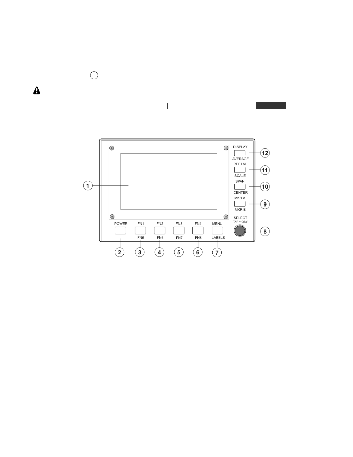
To get started using your P3 right away, please read this page and the two pages that follow, trying each of the
controls. The text uses braces to refer to numbered elements in the front- and rear-panel illustrations below. For
1
example, {1} refers to
The first thing you need to know about the P3 is that most switches have two functions. Tap (press
briefly) to activate the function labeled above a switch. Hold activates the function labeled below the switch. In
the text, tap functions are shown like this: DISPLAY . An example of a hold function is AVERAGE. Additional
typographical conventions are shown on the previous page.
, the display. Later sections provide greater detail on all aspects of P3 operation.
4
Page 5
K3’s built before September 2009 should have the I.F. Buffer Gain Modification installed for
best weak-signal display on the P3. This modification changes a single resistor to increase the
I.F. output from the K3 by about 10 dB. A modification kit consisting of the resistor and
Connections
IMPORTANT
installation instructions is included with your P3.
This modification is not required for K3 RF boards version H3 and later.
Connect a power supply to the
IMPORTANT: You may use the e K3 rear panel
10-15 VDC input jack {18} (see Specifications, page. 8).
12VDC OUT jack with the P3 alone.
If you have the P3SVGA option, the jack must be labeled 1.0 A MAX SWITCHED. Older
K3’s were limited to 500 mA, which is adequate to power the P3 without the SVGA, but
not the P3 with the SVGA option enabled. If your K3’s 12VDC OUT is limited to 500
mA, you can install, or have Elecraft install, a mod kit to increase the current available to
1 Ampere. Order the K312MDKT.
Connect a coaxial cable between the
When used with a K3, connect the cable to the
When used with a K3, connect a Male-Female DE-9 cable between the
IF IN {15} and the I.F. output of your transceiver.
IF OUT on the K3’s rear panel..
XCVR connector
{19} and the K3’s rear-panel RS232 connector.
If you have the P3SVGA Option installed:
Connect your external display to EXT DISP {16}.
Plug your USB keyboard into the KEYBOARD connector {22}.
Connector openings {17} and {21}, and are provided for future use.
The Basics
Turn on the power supply that is supplying the P3. If power is obtained from the 12VDC
OUT jack of a K3, turn on the K3. If necessary, press POWER {2} to turn on the P3. You
can position a jumper to have the P3 turn on automatically with the K3 (Page 30).
TAP and HOLD Functions: Tapping briefly activates the function labeled in white above a
switch. Holding for about 1/2 second activates the function labeled in yellow below a
switch. Try tapping
MENU {7} to bring up the main menu. Rotate
SELECT {8} knob to
scroll through the menu entries. Tapping the knob selects the entry currently displayed.
Tap the knob again to deselect the entry. Tap
MENU {7} to exit the menu.
Tap DISPLAY {12} to cycle between spectrum and waterfall display modes (Page 14).
Activating many functions enables the SELECT {8} knob so you can adjust the
parameter associated with the function. The current parameter value is shown on the screen
{1}. You can exit and save the parameter by tapping the same key a second time, even for
hold functions.
For hold functions, you can also hold the key a second time to exit parameter-entry mode.
In the case of the hold functions associated with the four keys along the
right edge of the front panel
{9-12}, holding the key a second time also
de-activates the function itself. For example, holding (CENTER) a second time returns the
display center frequency to the transceiver frequency and holding
(MKR B) a second time turns off marker B.
For best frequency accuracy, especially when using narrow spans, perform the frequency
calibration procedure described on page 30.
5
Page 6
Other
Features
Hold LABELS {7} to toggle on or off the function key labels located at the bottom of the
screen, just above the function keys (Pages 11 and 12).
Tap
Tapping the
Tap MKR A {9} or hold MKR B {9} to turn on marker A or B. Rotate the SELECT
To return from the last QSY ("undo" function), hold the
MENU {7} and use the SELECT knob {8} to scroll through the list. You can tap or
hold one of the function keys {3-6} to assign the currently-displayed function to the key. If
the function key labels are on, the label for that key will change to show the selected
function (Page 11).
SELECT knob {8} while the menu is active causes the currently-selected
menu function to execute. Select LCD Brt from the menu and tap the knob. The knob now
adjusts the brightness of the LCD display backlight. Tap the knob again to exit the
selection or tap MENU {7} to select a different menu item. Some menu items are toggle
functions. Instead of changing the parameter by turning the
automatically whenever the knob is tapped. The new value is displayed briefly near the top
of the spectrum display. Menu items are listed on page 33.
knob to place the selected marker at a desired frequency on the display. Markers may be
used to measure the frequency of an interesting signal and, if the transceiver is a K3,
tapping the knob will QSY (change the frequency of) the K3 to that frequency.
controls the K3's VFO A and MKR B controls VFO B. The marker colors match the
corresponding VFO cursors to emphasize the correspondence. Whichever marker is
currently selected is the one that causes the K3 to QSY (Page 11).
SELECT knob, it changes
MKR A
SELECT knob pushbutton. To
turn off marker A, tap
MKR A {9} while marker A is selected. To turn off marker B,
hold MKR B {9} while marker B is selected.
Tap
Hold CENTER {10} to set the center frequency of the display (Page 12). This function
Tap
Hold SCALE {11} to set the scale, or range, of both the spectrum and waterfall displays.
Hold AVERAGE {12} to turn on display averaging and allow adjustment of the averaging
SPAN {10} to set the frequency span of the display. The start and stop frequencies are
displayed at the top (left and right edge respectively) of the spectrum window (Page 11).
may be disabled when in tracking mode via the MENU:CenterEn function.
REF LVL {11} to set the amplitude reference level of the display, both spectrum and
waterfall. The term "reference level" means the signal level that corresponds to the bottom
of the spectrum display (Page 12).
For example,"60 dB" means that the bottom of the display is 60 dB below the top (Page
12).
time (Page 12).
6
Page 7

Introduction
This comprehensive manual covers all the features
and capabilities of the Elecraft P3 panoramic
display. We recommend that you begin with the
Quick-Start Guide (page. 4). The Front Panel
(page. 10) and Rear Panel (page. 13) sections are
for general reference. Basic Operation (page. 13)
and Advanced Operation (page. 17) fill in the
details of the full capabilities of the P3.
P3 Features
The P3 offers a number of advanced features to
enhance performance and versatility:
Ergonomic Design
Uncluttered interface.
No unused controls on the screen.
Field Upgradable
Software defined architecture so many new
features will require only a simple firmware
update using the provided PC utility
program.
Room inside for future hardware updates.
Compatible Receivers/Transceivers
May be used with any receiver having an
I.F. output between 455 kHz and 21.7 MHz
(including the Elecraft K2 with suitable
modification). The P3 is usable with
frequencies as low as 300 kHz.
Integrates very closely with the Elecraft K3
with point-and-click QSY and an “undo”
feature with simple control press to return
to the previous frequency.
Easy Set-Up
Only two cables for basic operation (I.F.
and power).
Optional additional connections provided
for transceiver communications, a personal
computer and optional accessories.
No configuration or calibration is required.
Display
Bright, high-resolution, full color display.
Efficient LED backlight for long life and
low power consumption.
Both fixed-tune and transceiver-tracking
modes for the display frequency.
Both Spectrum and Waterfall displays.
Fast display update.
Up to 200 kHz span.
Frequency resolution automatically
increases as span is decreased.
Excellent sensitivity and dynamic range.
P3SVGA Option
The P3SVGA Super Video Graphics Array option
adds wide screen display capability to the P3 with
enhanced data terminal operations that permits
sending text from a keyboard attached to the P3,
storing messages in memory that may be recalled
with a simple keystroke, and transmitting a stored
message at regular intervals. The P3SVGA features
a dedicated, high-speed Fast Fourier Transform
(FFT) processor that performs a 2048 point FFT in
parallel with the P3’s existing processor for a much
higher frequency resolution per dot on the larger
screen. The P3SVGA also includes an interface for
a future USB option that will permit direct digital
mode operation via the K3 and P3 with data display
on the P3 and P3SVGA screens.
The P3SVGA adds three connectors to the P3 rear
panel: KEYBOARD, EXT. DISPLAY and AUX
DATA. Only the KEYBOARD and EXT.
DISPLAY connectors are active at this time. The
AUX DATA connector is reserved for future use.
The P3SVGA supports the following video
resolutions:
1024 X 768
1280 X 1024
1440 X 900
1920 X 1080
Note that 1440 x 900 will display correctly on
1920 x 1080 monitors.
7
Page 8

Specifications
I.F. Frequency Range:
455 kHz to 21.7 MHz (usable with frequencies as low as 300 kHz)
Noise Figure:
Blocking Dynamic Range:
Absolute Level Accuracy:
Relative Level Accuracy:
Display Update Rate:
Amplitude Scale:
Span:
Resolution Bandwidth:
Power Requirements:
Weight:
Size:
< 10 dB measured at P3 input typical
> 120 dB (500 Hz bandwidth) typical
± 3 dB plus display resolution after calibration at S9 (-73 dBm)
± 0.1 dB plus display resolution
Selectable 1 Hz to 20 Hz (slower at narrowest spans)
10 dB minimum, 80 dB maximum
2 kHz minimum, 200 kHz maximum
Span / 450, 8 Hz minimum
10 to 15 VDC, 0.5 A maximum without the P3SVGA option; 0.7 A with the
P3SVGA option enabled.
5.5 lbs (2.5 kg)
Enclosure only, 4.0 x 6.1 x 10.0 in., HWD (10.2 x 15.6 x 25.4 cm). With
projections, 4.4 x 6.1 x 11.8 in. (11.2 x 15.6 x 30.0 cm).
8
Page 9

Customer Service and Support
Technical Assistance
You can send e-mail to k3support@elecraft.com and we will respond quickly – typically the same day
Monday through Friday. If you need replacement parts, send an e-mail to parts@elecraft.com
assistance is available from 9 A.M. to 5 P.M. Pacific time (weekdays only) at 831-763-4211. Please use e-mail
rather than calling when possible since this gives us a written record of the details of your problem and allows us
to handle a larger number of requests each day.
Repair / Alignment Service
If necessary, you may return your Elecraft product to us for repair or alignment. (Note: We offer unlimited email
and phone support, so please try that route first as we can usually help you find the problem quickly.)
IMPORTANT: You must contact Elecraft before mailing your product to obtain authorization for the
return, what address to ship it to and current information on repair fees and turnaround times. (Frequently we
can determine the cause of your problem and save you the trouble of shipping it back to us.) Our repair location
is different from our factory location in Aptos. We will give you the address to ship your kit to at the time of
repair authorization. Packages shipped to Aptos without authorization will incur an additional shipping charge
for reshipment from Aptos to our repair depot
.
. Telephone
Elecraft 1-Year Limited Warranty
This warranty is effectiv e as o f the date of first con sumer purchase (or if sh ipped from the factory, the date the
product is shipped to the customer). It covers both our kits and fully assembled products. For kits, before requesting
warranty service, you should fully complete the assembly, carefully following all instructions in the manual.
Who is covered: This warranty covers the original owner of the Elecraft product as disclosed to Elecraft at the time
of order. Elecraft products transferred by the purchaser to a third party, either by sale, gift, or other method, who is
not disclosed to Elecraft at the time of original order, are not covered by this warranty. If the Elecraft product is being
bought indirectly for a t hird party, the third party’s name and address must be provided at time of o rder to ensure
warranty coverage.
What is covered: During the first year after date of purchase, Elecraft will replace defective or missing parts free of
charge (post-paid). We will also correct any malfunction to kits or assembled units caused by defective parts and
materials. Purchaser pays inbound shipping to us for warranty repair; we p ay shipping to return the repaired
equipment to you by UPS ground service or equivalent to the continental USA and Canada. For Alaska, Hawaii, and
other destinations outside the U.S. and Canada, actual return shipping cost is paid by the owner.
What is not covered: This warranty does not cover correction of kit assembly errors. It also does not cover
misalignment; repair of damage caused by misuse, negligence, or builder modifications; or any performance
malfunctions involving non-Elecraft accessory equipment. The use of acid-core solder, water-soluble flux solder, or
any corrosive or conductive flux or solvent will void this warranty in its entirety. Also not covered is reimbursement
for loss of use, inconvenience, customer assembly or alignment time, or cost of unauthorized service.
Limitation of incidental or consequential damages: This warranty does not extend to non-Elecraft equipment or
components used in c onjunction with our products. Any su ch repair or replacem ent is the res ponsibility of the
customer. Elecraft will not be liable for any special, indirect, incidental or consequential damages, including but not
limited to any loss of business or profits.
9
Page 10

Front Panel
This section describes all front panel controls and the liquid crystal display (LCD). Operating instructions are
covered in later sections.
Control Groups
Primary controls (page 11): These keys are hard-
coded with permanent function assignments. They
provide the most important operational features
needed for basic panadapter operation, including
display options, amplitude scaling, frequency
control and markers.
Programmable function keys (page 12): The
function keys may be assigned to any of the
functions in the MENU list. These include less-used
operational features, test functions, and setup and
calibration routines.
10
Page 11
Display
The 480x272-pixel, color TFT-LCD display is used
both for the panadapter spectrum and waterfall
graphics as well as for general-purpose information
needed by the operator. All graphics and text are
bit-mapped and so are software-defined. The
backlight brightness and the text size can be
changed via a
MENU entry (Page 33).
Primary Controls
POWER Turns the P3 on or off. The P3 may be
configured to turn on automatically whenever
power is applied, such as when it is powered from a
K3 transceiver, by moving a jumper on the rear-
panel I/O board (see Configuration on page 30 for
details.) Holding the POWER switch for more than
10 seconds places the P3 in boot-load mode, ready
to receive new firmware via the RS232 PC
connector. If you do this accidentally, simply cycle
the POWER to restore normal operation.
MKR A and MKR B Selecting one of these
functions causes a marker to appear on the display,
using different colors for A and B. The marker
frequency can be adjusted by turning the
SELECT knob. If the transceiver is a K3 and it is
connected to the P3 via RS232, then tapping the
knob changes the frequency of (QSY) the K3 to that
frequency.
MKR B controls VFO B. The marker colors match
the corresponding VFO cursors to emphasize the
MKR A controls the K3's VFO A and
correspondence. Whichever marker is currently
selected is the one that causes the K3 to QSY. To
return from the last QSY ("undo" function), hold
the
SELECT knob pushbutton.
To turn off
MKR A, tap the key while marker A is
selected. To turn off MKR B, hold the key while
marker B is selected. When a marker is turned back
on after having been turned off, it will come back at
the same frequency unless it is off-screen, in which
case the marker defaults to the center frequency.
When another function that uses the
SELECT
knob is activated, the marker(s) stay visible and
when that other function is de-selected the last
active marker automatically becomes active again.
SPAN Sets the frequency span of the display. The
available range is 2 kHz to 200 kHz. The start and
stop frequencies are displayed at the top (left and
right edge respectively) of the spectrum window.
11
Page 12
CENTER sets the center frequency of the display,
which is also displayed at the top center of the
spectrum window when in tracking mode. If
MENU:CenterEn is set to OFF, then this function is
disabled for tracking mode. If the transceiver is a
K3, the center frequency defaults to the VFO A
frequency of the K3, but it may be tuned above and
below that value. It will then track any changes in
the K3’s VFO A.
In fixed-tune mode as well, CENTER sets the
center frequency of the display, however it does not
track the K3 VFO but stays at a fixed frequency. If
desired, you can set the center frequency to readjust automatically by setting the proper mode in
MENU:FixMode In both fixed and tracking modes,
hold the CENTER key a second time to return the
center frequency to the K3's VFO A frequency.
REF LVL Sets the amplitude reference level of the
display, both spectrum and waterfall. The term
"reference level" means the signal level that
corresponds to the bottom of the spectrum display
and the minimum signal level (dark blue) of the
waterfall. The amplitude labels that appear along
the left edge of the spectrum display may be in dBm
or S-units plus dB over S9, depending on the setting
of MENU:Lvl Mode. If the transceiver is a K3, the
amplitude is that of the signal at the K3 antenna
input, with the state of the K3's attenuator and
preamp taken into account. Tap any key to de-select
the parameter entry.
Menu
MENU Accesses an alphabetical list of functions
(see Menu Functions, page.33). Scroll through the
list with the
SELECT knob and tap the knob to
select an item. For items with only two or three
values, tapping the
SELECT knob toggles
between the parameter values. For other items, you
can turn the
SELECT knob to choose the
parameter value. Tapping the knob a second time
un-selects the item and exits the menu. If you wish
to terminate the item but keep the menu active, tap
MENU. When you wish to exit the menu, tap
MENU again.
Programmable Function Keys
Most menu functions can be assigned to a function
key by tapping or holding the FN1 – FN4 or FN5 –
FN8 key while the menu item is displayed but not
selected. The label for that function key will then
change to the function name (when labels are turned
on with the LABELS key).
LABELS toggles the function key labels on and off.
Note that the function keys are still active even
when the labels are turned off.
SCALE Sets the scale, or range, of both the
spectrum and waterfall displays. For example, "60
dB" means that the bottom of the display is 60 dB
below the top. Tap any key to de-select the
parameter entry.
DISPLAY Toggles between the spectrum, and
combination spectrum/waterfall display modes.
AVERAGE Turns on display averaging and allows
adjustment of the averaging time, in units of the
display update period. To de-select parameter entry
and turn off averaging at the same time, hold the
key a second time. To de-select parameter entry
while leaving averaging turned on, tap the key.
12
Page 13

Rear Panel Connectors
I.F. Signals: IF IN is a BNC jack that connects to
the intermediate-frequency output connector of the
transceiver (IF OUT on the K3). This should be a
buffered, low-level, high-bandwidth signal from the
receiver that is tapped off at a point before the highselectivity filters.
IF OUT is a BNC jack that may be connected to
any other device that needs the I.F. output signal
from the transceiver. When the IF OUT switch is in
the ON position, the IF IN signal is directed to a 3
dB splitter whose outputs feed both the P3 and the
IF OUT connector.
for downloading new firmware and for sending and
receiving commands to the P3 and K3 (if
connected). To set the baud rate, refer to the RS232
Menu entry on page 33. The baud rate also may be
set by using the same RS232 command (BR) as for
a K3. Refer to the K3 or P3 Programmer’s
Reference for details. To download firmware to the
K3, see Updating K3 Firmware on page 29.
Power: 10-15 VDC is a standard 2.1 mm barrel
connector for a 10-15 VDC supply. See
Connections on page 5 if you wish to take power
from the K3’s
12VDC OUT jack.
RS232 XCVR is a male DE-9 connector that
connects to the RS232 port on a K3 (if used) using
a standard 9-pin serial extender cable. It should be a
straight-through cable (not a null modem) with a
female connector on one end and male connector on
the other. Note that communications between theK3
and the P3 are always at a data rate of 38400 baud
(see figure below). The K3 baud rate is set
automatically by the P3 and cannot be changed at
the K3.
RS232 PC is a female DE-9 that optionally may be
connected to a personal computer that can be used
RS232 Communications Path through the P3.
The following are present only if the P3SVGA
option is installed:
KEYBOARD: USB jack for a USB keyboard or
thumb drive (mass storage device). Apple
keyboards are not supported at this time.
EXT.DISPLAY: Output to an external SVGA
monitor.
SENSOR and AUX DATA: For future use.
13
Page 14
Basic Operation
This section covers the fundamentals of P3
operation. Once you're familiar with the P3, please
go on to Advanced Operating Features (page.17).
Using Tap/Hold Switches
Most P3 switches have two options. Tapping
(pressing for less than 1/2 second) activates the
function labeled in white above the switch. Holding
(pressing for more than 1/2 second) activates the
function labeled in yellow below the switch.
Initial Power-Up
Connect a power supply, I.F. input and
(optionally) an RS232 cable (page 13).
Press
POWER to turn the P3 on, if it is not on
already. The screen should light and you should
see a spectrum or combined spectrum and
waterfall display. If a K3 is connected via
RS232 you should see the correct frequency at
the top center of the display.
Configuring the Display
Tap DISPLAY to cycle between spectrum and
combined spectrum and waterfall displays.
Hold AVERAGE to turn on averaging and to set the
averaging time constant with the
You can hold AVERAGE again to turn off
averaging or just tap the same key to clear the
parameter-entry text from the display while leaving
averaging enabled.
Hold LABELS to show or hide the function key
labels.
SELECT knob.
There are also several MENU functions that
configure the display, such as LCD Brt (display
brightness), Peak hold, Freeze display, Font size
and Waterfall height.
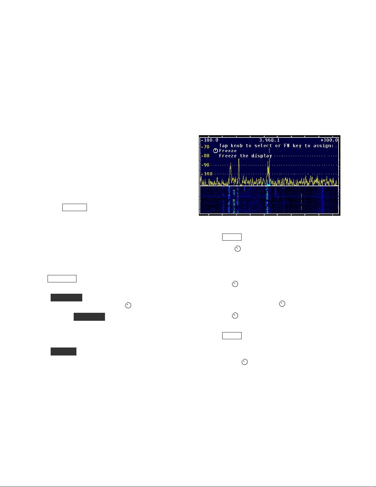
Using the Menu
Typical Display Showing a Menu Selection.
Tap
Turn the SELECT knob to scroll through an
Tap the
Most functions have a parameter which can
Tap the
Tap
Some menu items are toggle functions. The
MENU to access the menu.
alphabetical list of available menu functions, as
documented in the Menu Functions section
(page.33).
SELECT knob to select a function.
then be adjusted with the
SELECT knob again to exit the
function.
MENU again to exit the menu.
parameter changes automatically every time
you tap the
SELECT knob.
SELECT knob.
14
Page 15
Programmable Functions
Adjusting the Frequencies Displayed
Most MENU functions can be assigned to any
programmable function key, FN1 to FN8. Tap or
hold the desired function key while the function is
visible on the display but not selected by tapping
the
SELECT knob. The function name then
becomes the function key label which can be seen if
labels are currently displayed. To un-assign a
function key, select MENU:FN Erase and tap or
hold the function key you wish to erase.
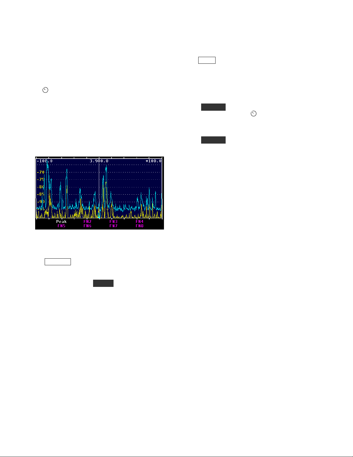
Some menu items are much more useful when
assigned to a function key. Examples are
Freeze display.
and
PEAK assigned to Function Key FN1.
Peak hold
Adjusting the Amplitude
Tap SPAN to adjust the range of frequencies that
can be seen on the display at one time. The start and
stop frequencies are indicated at the top left and
right of the display. They are shown as offsets from
the center frequency in tracking mode and as the
actual RF frequencies in fixed-tune mode.
Hold CENTER to adjust the display center
frequency by turning the
function may be disabled for tracking mode via
MENU:CenterEn.
Hold CENTER again to re-center the display on the
transceiver VFO frequency.
When used with the K3, an RF frequency is shown
at the top center of the display. In tracking mode, it
is the display center frequency, which normally is
the K3 VFO A frequency. In fixed-tune mode it is
always the K3 VFO A frequency. For transceivers
other than the K3 it is the difference between the
center frequency and the current transceiver
frequency, normally zero.
The tic marks that appear along the top and bottom
edges of the spectrum and waterfall widows
indicate RF frequency in integer multiples of 0.5, 1,
2, 5, 10 or 20 kHz, depending upon the span.
SELECT knob. This
Tap REF LVL to adjust the reference level, which
is the signal level that corresponds to the bottom of
the spectrum display and the low-signal level of the
waterfall display. Hold SCALE to adjust the
"vertical gain" of the display. For example if the
reference level is set to -100 dBm and the scale to
30 dB, then the top of the spectrum display is at -70
dBm and the bottom at -100 dBm.
The waterfall display is most useful if the reference
level is adjusted to place the noise level near the
bottom of the display and the scale is adjusted so
that the strongest signals of interest are near the top.
15
Page 16
Using Markers
Waterfall Markers
Tap MKR A to turn on marker A and allow you to
change the marker frequency by rotating the
SELECT knob. To determine the frequency of a
signal, move the marker so that it overlays the
carrier and read the frequency from the display. For
single sideband signals, place the marker where the
carrier would be if it were transmitted, i.e. on the
lower (left) edge of an upper sideband signal and on
the upper (right) edge of a lower sideband signal.
If a K3 is connected, you can QSY (change the
frequency of) the K3's VFO A to the marker A
frequency by tapping the
return to the previous frequency, hold the knob. To
turn off marker A, tap
Hold MKR B to turn on marker B and allow you to
change the marker frequency by rotating the
SELECT knob. If a K3 is connected, you can
QSY the K3's VFO B to the marker B frequency by
tapping the
previous frequency, hold the knob. To turn off
marker B, hold MKR B again.
To turn off a marker you must first make it active, if
necessary, by tapping MKR A or holding MKR B.
Then tap or hold the key a second time to hide the
marker.
If some other function that uses the
knob is activated, the marker stays on and
automatically becomes active again (you can adjust
it with the knob) when the other function is
terminated. The tap-to-QSY function affects VFO
A if marker A is active and VFO B if marker B is
active.
SELECT knob. To return to the
SELECT knob. To
MKR A again.
SELECT
Select MENU:WfallMkrs. Tapping the
SELECT knob will turn the waterfall markers
on, causing the marker line(s) to travel down into
the waterfall display, or turn the markers off.
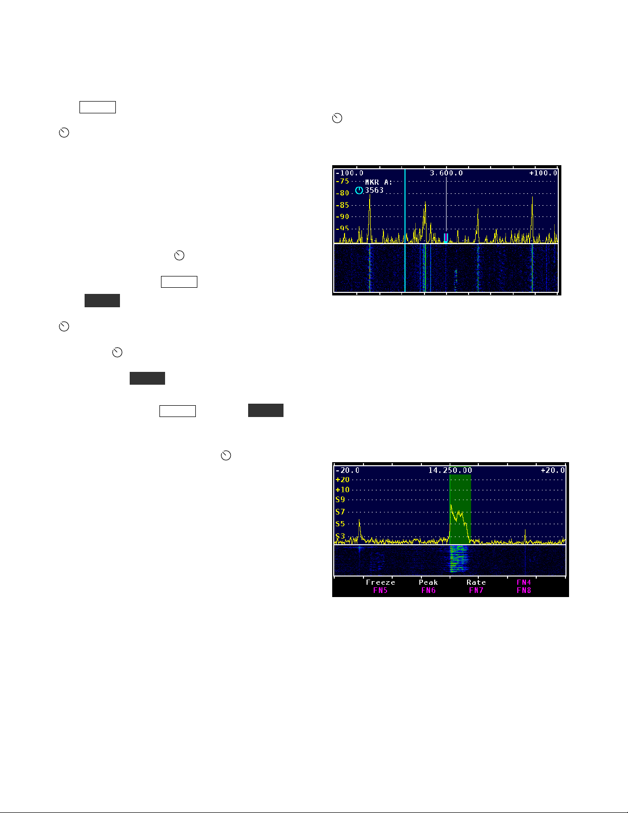
Marker A Enabled at 3563 KHz for Both Spectrum
and Waterfall.
Using Cursors
When used with a K3 transceiver, cursors show the
position of the A and B VFOs, The position and
width of each cursor shows the passband being
received. Two cursor shapes may be selected using
MENU:CURSOR, a translucent bar cursor or a “U”
shaped cursor at the bottom of the spectrum display.
When a marker is turned on, it will be at the same
frequency as the last time it was on unless that
frequency is off-screen. In that case the marker is
automatically reset to the display center frequency.
(If you lose a marker off-screen, just turn it off and
on again to return it to the center frequency.)
When you change bands on the K3, the markers are
automatically set at the new center frequency.
For best frequency accuracy, especially when using
narrow spans, perform the frequency calibration
procedure on page 31.
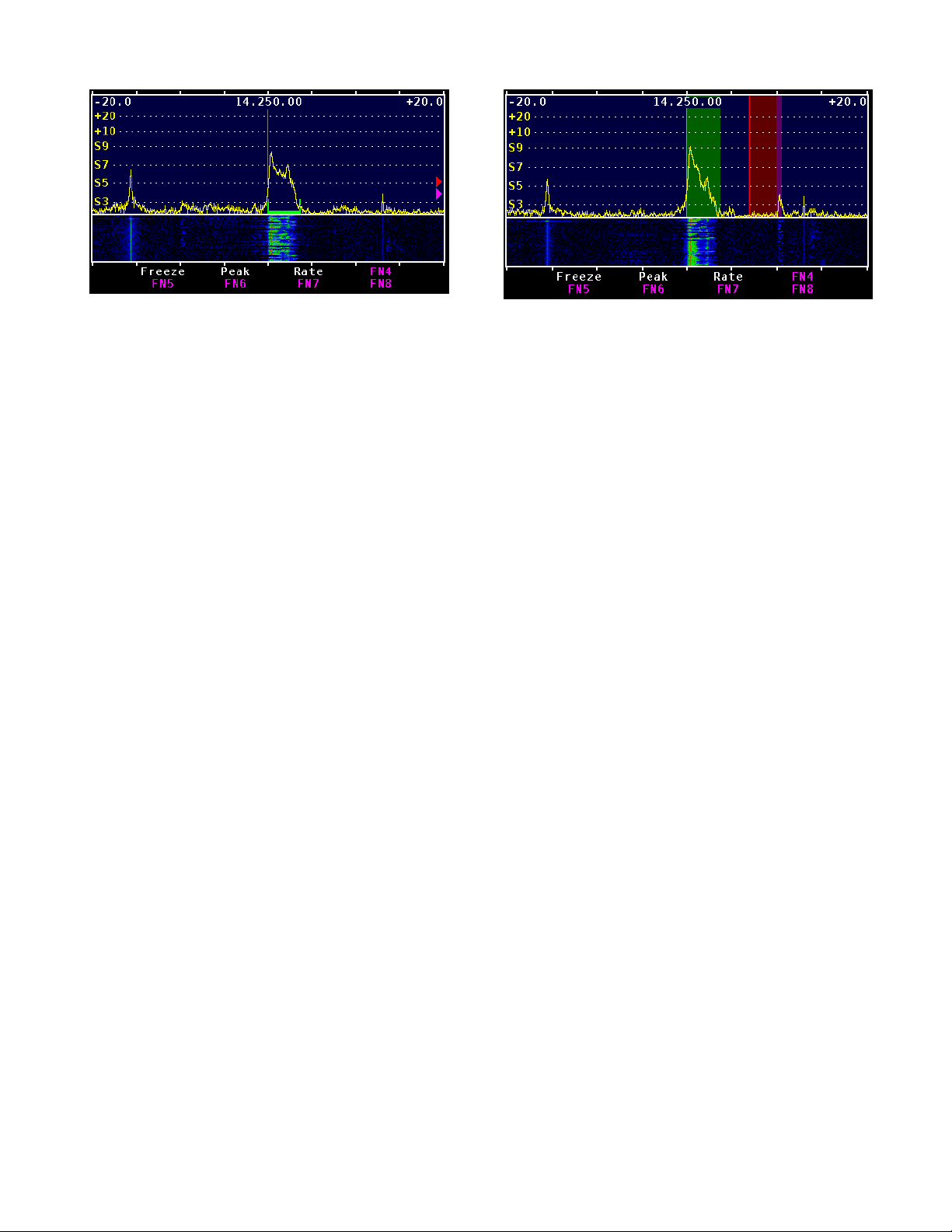
Bar Cursor on Upper Sideband Signal at 14.250 kHz
16
Page 17
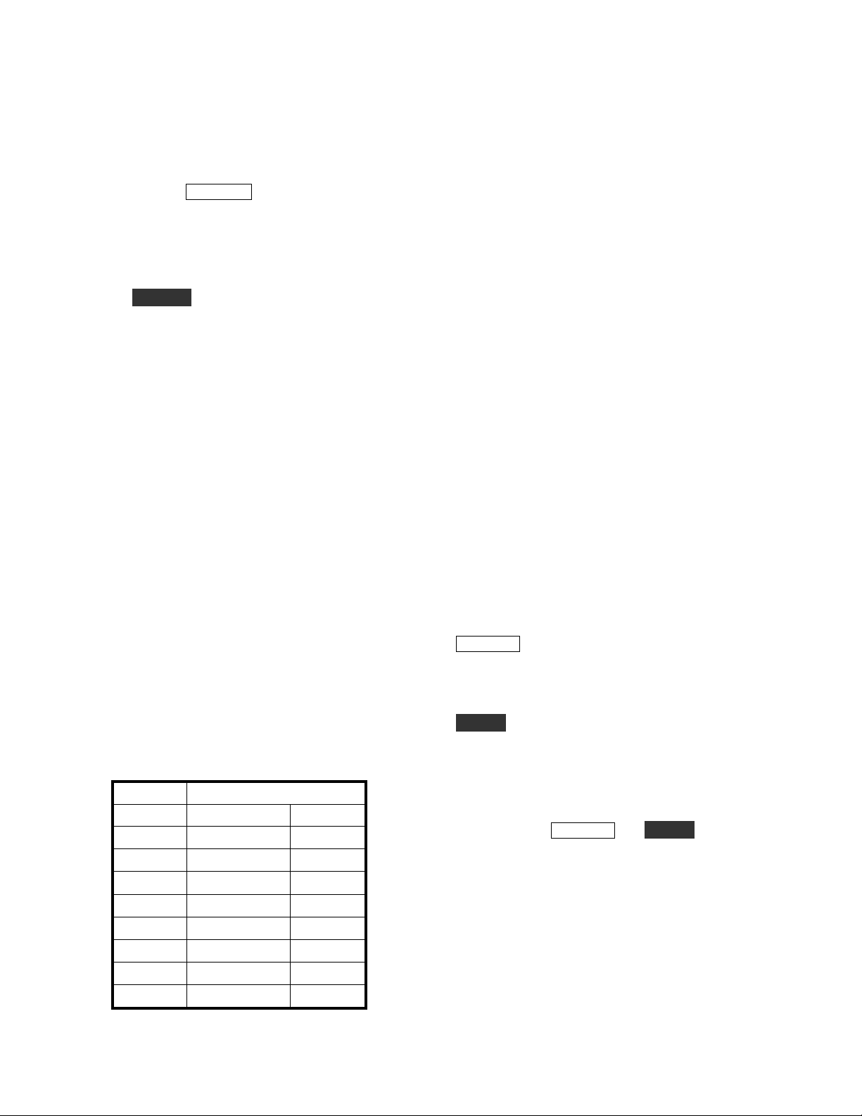
“U” Cursor on Upper Sideband Signal at 14.250 kHz
VFO A has a green cursor and VFO B has a
magenta cursor unless split mode is activated at the
K3. In split mode, the VFO B cursor changes to red
as a reminder that you will transmit on that
frequency. Similarly, if XIT is on, or if split is off
and RIT is on, a new red cursor appears at the
transmit frequency.
Red Bar Cursor Showing Transmit Frequency Above
the Receive Frequency
Whenever a cursor is tuned off-screen a small arrow
of the same color appears at the bottom left or right
of the spectrum window to indicate the direction to
the missing cursor
The VFO B cursor may be turned off using
MENU:VFO B. Tap the knob to select ON or OFF
as desired.
17
Page 18
How to Set Up and Interpret the P3 Display
There are several options to customize the layout of
your P3 display.
spectrum-only and spectrum-plus-waterfall display.
The height of the waterfall can be adjusted with
MENU:Waterfall. The function (FN) key labels
appear at the bottom of the screen by default. You
can hide them to maximize the screen area by
holding LABELS. The FN keys remain active even
when the labels are hidden. Another trick to
maximize viewing area is to choose a smaller type
font via
MENU:Font.
DISPLAY switches between a
Spectrum Display
The spectrum display on a panadapter is similar to
the display on a laboratory spectrum analyzer. The
horizontal axis is frequency and signal strength is
represented by the vertical height of each signal.
The P3's spectrum display is similar to most in that
the signal height is proportional to the logarithm of
the amplitude, represented in decibels (dB). Each 3
dB represents a doubling of power and 10 dB
means ten times the power.
The vertical scale at the left edge of the spectrum
display may be in units of dBm or S-units, as
selected by MENU:Lvl Mode. The dBm unit
means decibels with respect to one milliwatt. 0
dBm is one milliwatt, +10 dBm is 10 milliwatts, -10
dBm is 1/10 milliwatt and so on. An S9 signal is
normally considered to be 50 microvolts into 50
ohms, which is -73 dBm, an easy number for a ham
to remember! Assuming the standard 6 dB per Sunit, the following table applies.
S-Units Signal Level
S9 -73 dBm
S8 -79 dBm
S7 -85 dBm
S6
S5 -97 dBm
S4 -103 dBm
S3 -109 dBm
S2 -115 dBm
S1 -121 dBm
-91 dBm 6.25 V
50 V
25 V
12.5 V
V
1.56 V
0.78 V
0.39 V
0.2 V
You would expect the S meter on the K3 and the
signal on the P3 display to indicate the same level if
both the K3 and the P3 are properly calibrated,
however there are several reasons why that might
not be the case. One is that the P3 is not affected by
the preamplifier and attenuator in the K3. If the K3
CONFIG:SMTR MD is set to NOR, the S meter
reading changes when you turn on or off the
preamplifier and attenuator. To prevent that,
change the setting to
The noise level will generally be lower on the P3
display compared to the K3 S meter. The reason is
that the effective bandwidth of the P3 is generally
one display pixel, which is approximately span /
450. The smaller the bandwidth, the less noise. For
example, if the span is 45 kHz, the effective P3
bandwidth is 45,000 / 450 = 100 Hz. If the K3
bandwidth is 400 Hz, it will show a 6 dB (one Sunit) higher noise level than the P3.
A similar thing happens with spread-out signals like
SSB. Even at the maximum 200 kHz span, the P3's
effective bandwidth is only about 440 Hz so that
not all the SSB signal is within one pixel. That's
why the P3 tends to read a lower level on SSB
signals than the K3 S meter.
REF LVL (reference level) on the P3 shifts all the
signals up or down. The level that you are adjusting
is the signal level at the bottom of the display,
measured in dBm.
SCALE is used to expand or contract the vertical
scale. Think of it as a vertical gain control. The
scale is defined as the dB difference between the
top and the bottom of the display. For example, if
the reference level is -100 dBm and the scale is 20
dB, then a signal at the top of the display is at -80
dBm. For both REF LVL and SCALE, turning the
knob clockwise makes the signals taller.
The P3 automatically compensates for the
preamplifier and attenuator in the K3. When you
turn them on or off, the signal levels on the P3
should stay the same. If the I.F. output modification
has been done on the K3 (see note at the top of
page 5), the indicated dBm level should be the
signal level at the K3 antenna input. Perhaps
counter-intuitively, this means that if you turn on
ABS.
18
Page 19

the preamplifier in the K3, the noise level displayed
on the P3 may decrease, rather than increase. That
is because the P3 automatically reduces its gain
when the K3 preamplifier is turned on, in order to
keep the signal levels the same.
Waterfall Display
The waterfall allows you to see a history of band
activity for the past few seconds. Like the spectrum
display, the horizontal axis is frequency but in this
case the vertical axis is time. Signal amplitude is
represented by colors, from dark blue for weak
signals, then brighter blue as signals increase in
strength, through shades of green, yellow and red
for the strongest signals. Each horizontal line
represents one update of the spectrum display.
As each new line is written the old ones are shifted
down, creating a waterfall effect.
While the spectrum display is better at accurately
displaying signal strength and the shape of a
signal's modulation, it can only show what is
happening right now. The waterfall is better for
showing transient signals, such as a DX station
running a pileup that only transmits for a few
seconds at a time. Often, you can easily see a weak
fading signal on the waterfall that is invisible on the
spectrum display.
The scaling of the waterfall is the same as for the
spectrum. That is, the bottom of the spectrum
display corresponds to dark blue on the waterfall
and the top corresponds to bright red. For maximum
visibility of signals on the waterfall, it is best to set
REF LVL so that the noise level is right at the
bottom of the spectrum display and then expand
SCALE as much as possible while keeping signals
of interest below the top of the spectrum display.
That improves the color contrast on the waterfall
and makes weak signals appear to pop out of the
noise.
Averaging and Peak Hold
AVERAGE and then turn the knob. The averaging
time is in units of the spectrum update rate,
typically about 50 ms. You can apply averaging to
the waterfall as well by setting
On.
Peak hold is a way to display a memory of past
signals on the spectrum display. It shows the
strongest signals that have appeared at each
frequency since the last time peak mode was
enabled. To reset the peak trace, simply disable
peak hold and then re-enable it. This mode is most
useful if you assign
can turn it on and off at the touch of a button.
One use for peak hold is to monitor a dead band for
activity while you are away from the operating
position. If you glance at the display every now and
then you can see if any signals have appeared in the
meantime. Peak hold is also useful to see the shape
of a modulation spectrum. Since the sidebands are
continually changing with modulation, the peak is a
better indication of the spectrum than the
instantaneous value.
MENU:Peak to a FN key so you
MENU:Wfall Avg to
Span
Adjusting the span is yet another way to make weak
signals more visible. As you narrow the span, there
is less noise within the range of each frequency
display point. That reduces the apparent noise level
while the signal levels stay the same, which
increases the signal-to-noise ratio. At narrow spans,
signals that are difficult or impossible to hear
become visible, especially on the waterfall.
As mentioned before, it is useful to keep the noise
level right at the bottom of the display. The P3 can
automatically keep the noise level constant as you
adjust the span by setting the menu
MENU:SpanScale: REF LVL only. If you would
also like the level at the top of the screen to remain
constant as you adjust the span, set
MENU:SpanScale: REF LVL & Scale.
Another way to make weak signals more visible is
averaging. Because noise is random in nature,
averaging reduces the jaggedness of the noise
spectrum trace, making signals easier to pick out.
The more averaging the better the noise reduction,
but at the expense of a slower response. To turn on
averaging and adjust the averaging time, hold
Fixed-tune mode
When the P3 is used with a K3 transceiver, the
center frequency on the P3 screen normally follows
along as you tune VFO A on the K3. This is called
tracking mode. In this mode, the frequency
displayed at the top center of the screen is the
display center frequency, and the labels at the top
left and right show the frequencies of the left and
19
Page 20

right edges of the display, in terms of their offset
from the center. Usually, the VFO A frequency is
at the center of the P3 display unless you have
offset it with the P3's CENTER control. The
display can be re-centered at any time by holding
the CENTER key while already in center-frequency
mode, which can be accomplished by holding the
CENTER control twice.
In fixed-tune mode the frequencies on the P3
display stay fixed as you tune VFO A. The VFO A
cursor moves across the screen instead of always
being at the same position, as it is in tracking mode.
You can toggle between fixed-tune and tracking
modes via MENU:FixTrack. Fixed-tune mode is
only available with the K3 transceiver.
The selection of fixed-tune or tracking mode is
global, that is, it is the same on all bands and it is
remembered when cycling power. In fixed-tune
mode, the center frequency and span are stored in
non-volatile memory per band. When changing
bands or when turning on power, the last values
used on that band are remembered, unless that
would put the VFO A cursor off-screen, in which
case the display is re-centered on VFO A. The only
exception is Static mode, where the only way to
change the center frequency or span while fixedtune mode is in effect is to adjust the CENTER or
SPAN keys.
Typical Spectra
The three frequency labels at the top of the screen
have different meanings than they do in tracking
mode. The one at the center is always the VFO A
frequency, even when it is not at the center of the
display. The labels at the top left and right are the
actual RF frequencies that correspond to the left and
right edges of the display, rather than the frequency
offsets from the center.
If you tune VFO A past the left or right edge of the
screen, one of four things can happen depending on
the MENU:FixMode selection. If the mode is set to
"Full" then the center frequency jumps up or down
one full screen width whenever you tune past an
edge so as to keep the VFO A cursor on the screen.
If the mode is "Half", the center frequency jumps
one-half screen width. In "Slide" mode, it moves
the minimum amount necessary to keep the cursor
on the screen. In "Static" mode, the center
frequency is truly fixed; the VFO A cursor is
allowed to disappear off-screen. In both tracking
and fixed-tune modes, whenever either the VFO A
or VFO B cursor is tuned off-screen, a small arrow
at the bottom left or right of the display points in
the direction of the missing cursor. The arrow color
matches the cursor color.
When you switch between tracking and fixed-tune
mode, the span stays the same. The center
frequency also stays the same when switching from
tracking to fixed-tune mode, but defaults to the
VFO A frequency when going from fixed-tune to
tracking mode. In either mode, the center
frequency and span can be adjusted using the
CENTER and SPAN keys (unless the CENTER
key has been disabled for tracking mode with
MENU:CenterEn).
Below is a typical screen shot of the 40 meter band
during the day. At the center is a weak CW signal
that was inaudible on the K3 transceiver during
fades. It is hard to see on the spectrum display at the
top but is clearly visible on the waterfall. Just to the
right of that is a strong interfering carrier. At the far
right is another steady carrier and just to the left of
that is a spurious emission, probably from a
switching power supply, that is wavering back and
forth in frequency. A panadapter is a powerful tool
for tracking down interference.
This is another example of interference, this time
from a LAN router. The QRM includes both
wideband noise as well as discrete carriers and is
constantly heaving and writhing as the processor in
the router executes different portions of its software
routines.
20
Page 21

Spurious signals generated in the transceiver are
sometimes visible as well. As you tune the
transceiver you may see carriers that scroll across
the screen much faster than other signals,
sometimes tuning in the opposite direction. These
are created by high-order harmonics of the VFO,
BFO and other signal sources in the transceiver.
Normally you won't hear them in the receiver
unless one falls within the I.F. passband, but they
are easy to see on the panadapter display because of
its much wider bandwidth.
The following image shows a typical LSB spectrum
obtained in this way. Peak hold is enabled in order
to get a better view of the spectrum shape. Notice
that the low audio frequencies (on the right) are
much stronger than the high audio frequencies. A
flatter spectrum is considered desirable to improve
the signal's "punch" in the presence of noise and
interference, especially when speech compression is
used. The P3 is a handy tool for adjusting the
transmit equalizer in the K3.
This is a shot of a local AM broadcast station,
illustrating the use of peak hold to show the shape
of the modulation spectrum, which extends to plus
and minus 10 kHz from the carrier and then drops
off abruptly to meet FCC regulations.
Normally the P3 display is frozen while the K3 is
transmitting. However if you temporarily
disconnect the RS232 cable between the P3 and K3,
that function is disabled and it is possible to view
your own transmissions for test purposes. The
signal level is rather weak as it depends on random
leakage in the K3's I.F. chain, so you may need to
experiment with
REF LVL on the P3 and the power
level and frequency band on the K3 to get an
adequate signal. Also, the frequency may not be
exactly centered on the display due to the effect of
crystal filter offsets in the K3.
The previous image also illustrates an important
point when using markers. On SSB, the frequency
that is shown on the display of the K3 transceiver is
the suppressed carrier frequency. When you QSY
the transceiver using MKR A or MKR B on the P3,
that is the frequency the K3 will go to. So on bands
where LSB is used, you should place the marker
just above the spectrum of the SSB signal you are
trying to net (approximately in the center of the
above display) and for USB, place the marker just
below the spectrum.
21
Page 22

Advanced Operating Features
the
Basic P3
Use with Other Radios
The P3 can be used with any receiver or transceiver
that has means to output an intermediate-frequency
(I.F.) signal between approximately 455 kHz and
21.7 MHz. Frequencies a little beyond that range
can be used at reduced sensitivity.
The I.F. may be selected via
you are not sure what frequency is used by your
receiver, apply a test signal to the receiver antenna
and scroll through the menu list until you see the
signal on the display. Many receivers use an
inverted I.F., meaning that signals tune in the
opposite direction, so many of the selections
include that feature. As you tune the receiver
upwards in frequency the signal should move to the
left on the display.
If the correct I.F. is not in the list, the frequency of
the USER selection may be set manually via
MENU: Xcvr Def
.
MENU: Xcvr Sel. If
SELECT knob and the one with the vertical
arrows selects a character from a list by rotating the
knob.
Tap FN4 (EXIT) to return the P3 to normal
operation.
Use with Transverters
The I.F. output of many transceivers tunes
backwards. For example, the K3’s I.F. output is
inverted on all bands except 50 MHz. The P3 takes
this into account automatically. However, if you are
using an external transverter, the tuning direction
depends upon whether the band it converts down to
is the 50 MHz band (not inverted) or some other
band (inverted).
To configure the P3 so the displays moves as
expected regardless of the tuning direction, select
MENU:XV Invert, tap the SELECT knob, and
adjust the knob to select the desired transverter
band: 1-9. Tape the knob again to select either
“Inverted” or “Not Inverted.
See also Amplitude Calibration for Transverters on
page 33. If you are using your P3 with an Elecraft
K3, the K3 Owner’s manual contains more
information about working with transverters.
Xcvr Def Display.
Xcvr Def
and non-inverted I.F., change the name "USER" to
something else, and select the programming
language (currently either None or K3).
The
function (FN) keys with legends across the bottom
of the display as shown above. There are three keys
to set the frequency in 100 kHz, 1 kHz or 1 Hz
steps.
The FN2 and FN3 keys are used for changing the
transceiver name. The one with the horizontal
arrows selects the character position as you rotate
also allows you to select between inverted
Xcvr Def function temporarily re-defines the
Remote-Control Commands
Many P3 functions may be accessed by remotecontrol commands sent via RS232. These
commands use ordinary ASCII text, so they can be
tested using a terminal emulator or the Command
Tester tab in P3 Utility. When the P3's XCVR
RS232 port is connected to a K3, then both P3 and
K3 commands may be sent and received via the PC
RS232 port.
To distinguish them from K3 commands, P3
commands begin with the "#" symbol. For example,
"#RVM;" returns the P3 firmware revision and
"RVM;" returns the K3 main firmware revision. P3
remote-control commands are fully described in the
P3 Programmer's Reference.
22
Page 23

P3 Utility Program
Spectrum Display Fill
In addition to downloading firmware (page 29) the
P3 Utility can perform several other functions. For
example, it can upload a bitmap image of the P3
display which can be saved to a file or pasted into a
graphics program on the computer. Refer to the
Help menu in P3 Utility for more information.
P3SVGA Option
The following functions are applicable only if the
P3SVGA board is installed and enabled.
MENU and then turn the SELECT knob to
Tap
SVGA menu. Tap the SELECT knob enter the
sub-menu.
SVGA Display On/Off
The external display is activated automatically
when the P3 is turned on. You can turn the
external display off or on from the SVGA submenu. In the SVGA sub-menu, turn the
SELECT knob to SVGA en and then tap the
SELECT knob again to toggle between SVGA
and SVGA off.
on
SVGA Firmware Version
In the SVGA sub-menu, turn the SELECT knob
to
SVGA FW and then tap the SELECT knob
again to display the installed SVGA firmware
version.
Set Resolution
In the SVGA sub-menu, turn the SELECT knob
to
SVGA res and then tap the SELECT knob
again. Turn the
desired resolution. Note that there are two
1920x1080 resolutions available, normal and “alt”.
These have different pixel clock rates. Use the one
that works best on your monitor.
SELECT knob to select the
This setting fills the space below the spectrum line
or leaves it open as shown in SVGA Spectrum
Display Fill below. It does not have any effect on
the waterfall display or the spectrum display on the
P3’s internal screen. In the SVGA sub-menu, turn
the
SELECT knob to SVGA fill then tap the
SELECT knob to toggle the fill on or off.
SVGA Spectrum Display Fill.
SVGA Font Size
In the SVGA sub-menu, turn the SELECT knob
to
SVGA font and tap the SELECT knob again.
Turn the
SELECT knob to change the font size.
Three sizes are available, 0, 1 and 2, shown in the
upper left of the internal P3 display. The change
will appear after a brief interval on the SVGA
monitor so you can see the effect of the change
without leaving the menu.
SVGA Waterfall Color Bias
In the SVGA sub-menu, turn the SELECT knob
to
SVGA waterfall color bias and tap the SELECT
knob again. Turn the
SELECT knob to change
the bias value (shown in upper left corner of the P3
internal display). The change will appear
immediately on the SVGA monitor waterfall
display so you can see the effect without leaving the
menu.
SVGA Data Terminal Display
In the SVGA sub-menu, turn the SELECT knob
to
SVGA data and tap the SELECT knob again.
See Data Terminal Setup on the following page for
complete information on using the data terminal
functions.
23
Page 24

Data Terminal Setup
Data terminal mode adds three windows at the
bottom of the SVGA monitor: one for received
data, one for transmitted data and a status bar as
shown below. These windows occupy part of the
area used by the waterfall display. The height of
the status bar is fixed. The sizes of the receive and
transmit data windows, and the sizes of the fonts
used for them, are variable using the setup menu as
described below.
SVGA Display with Data Terminal Mode Enabled.
Decoding Text
The decoding of signals takes place in the K3. See
your K3 Owner’s manual for details about how to
configure the K3 to decode text in CW and each of
the data modes.
Adjusting the Receive and Transmit Windows
and Font Sizes
The area occupied by the receive and transmit data
windows depends upon the font size and monitor
resolution used. Since the data windows occupy
part of the space normally available to the waterfall
display, you may need to increase the size of the
waterfall display to provide room for them.
If the transmit data window size is set to zero, data
transmission is disabled, the transmit data window
will disappear and the keyboard becomes inactive.
To set the window and font sizes, tap
MENU and
then turn the SELECT knob to SVGA menu. Tap
the
SELECT knob enter the sub-menu. Turn the
SELECT knob to the desired parameter tap the
SELECT knob again. Turn the SELECT knob
to change the parameter:
SVGA WinR - Sets the size of the receive data
window (in lines).
SVGA WinT - Sets the size of the transmit
data window (in lines).
SVGA fntD - Sets the size of the font. 0 is the
smallest, 3 is the largest.
24
Page 25

Transmit Setup
Using the Keyboard
An upper case K in the right hand corner of the
SVGA display status bar (see SVGA Display with
Data Terminal Mode Enabled on page 24) indicates
Keyboard Shortcuts
KEYS FUNCTION
Ctrl-H
Backspace
Ctrl-Backspace
Ctrl-Alt-M
Ctrl-Alt-T
Ctrl-Alt-S
Ctrl-Alt-B
Esc
Scroll Lock
Ctrl-R
Opens help screen except when editing messages or macros. Press any key to exit.
Deletes character to the left.
Deletes word to the left.
Opens K3 macro entry pop-up window.
Opens text messages pop-up window.
Opens setup menu.
Starts beacon transmit.
Switches K3 to receive and clears the transmit data window.
Freezes receive data window. Press again to resume.
Switches the K3 to receive. If the K3 is transmitting data or CW, transmission
pauses.
that the keyboard is connected and active. Keyboard
shortcuts are listed below. (Hyphenated keys must
be pressed at the same time.)
Ctrl-T
Ctrl-C
Scroll Lock
|
Resume transmission
Clears the transmit and receive data windows.
Freezes the receive data window.
When inserted into a text message, causes the K3 to revert to receive mode at the
end of the message
NOTE: On-screen menus use the carat, ^ (upper case 6), to denote the Control (Ctrl) key
25
Page 26

Setup Options
The transmit mode options and text color
parameters that you can set are listed below. Press
Ctrl-Alt-S to open the setup menu on the SVGA
screen. This screen will cover the transmit data
window and status bar temporarily. Use the
up/down arrows on the keyboard to select a
parameter and the left/right arrows to change the
parameter. Pressing
in larger steps. Press
Ctrl-arrow changes the values
Esc to save the changes and
close the menu. The parameters are saved in nonvolatile memory so they will be retained after
power has been turned off and then on again.
Transmit Mode: CR, ^T, VOX
Allows you to control when text entered on the
keyboard is sent:
CR: The K3 will start transmitting the text
only after the
Enter key is pressed.
^T: The K3 will start transmitting the text
only after
Ctrl-T is pressed.
VOX: The K3 will transmit each character
as it is typed on the keyboard.
NOTE: Pressing
Ctrl-R will interrupt a
transmission. In CR or VOX modes, press
Enter to restart a transmission. In ^T mode,
press
Ctrl-T to restart the transmission.
Pressing
Esc stops the transmission and
clears any unsent text.
Transmit Timeout: 0 to 90,000 ms (0 to 90
seconds) in 200 ms (0.2 second) increments.
The length of time an idle signal will be transmitted
in PSK or RTTY modes after the last character is
sent. Any character entered on the keyboard during
this time will be sent and the timeout period will
start over. Pressing
| (the vertical bar) on the
keyboard will terminate the delay and return the K3
to receive mode immediately.
Transmitted Text Color: 1 to 50
The color of the text in the transmit data window
changes as each character is sent. Use this
parameter to choose the color of the characters after
they have been sent.
Tx Text Color: 1 to 50
Use this parameter to choose the color of the
unsent characters in the transmit data window.
Rx Text Color: 1 to 50
Use this parameter to choose the color of the text
shown in the receive data window.
Beacon Text Mem# and Beacon Interval
See Beacon Mode on page 27.
Text Message Entry
There are 50 text message memory locations available that can be used in CW, RTTY or PSK modes. Each
location can store up to 124 characters (including spaces). These messages are stored in non-volatile memory so
they will not be lost when power is cycled. Create a text message as follows:
Press
Ctrl-Alt-T to enter the text message window. The window opens on top of the data and status
windows. Press the up and down arrows to find an available (empty) message location (indicated by an
<empty> key assignment), or you can select a message that is no longer needed. The example
belowshows that memory location 1 is available.
Empty Text Message Location.
26
Page 27

Press
Enter to use the selected memory location.
Assigning a Recall Key.
Press the key(s) that you want to use to recall this message. In the example Editing a Message shown
below, the
ALT-B key combination was assigned to the message. If the name of the key does not appear
when it is pressed, it has already been assigned to another message. You must choose a different key.
Enter the text of the message. In this example the message is “Rig is an Elecraft K3 with P3/SVGA.”
Correct errors using the
Backspace, Ctrl-Backspace or Ctrl-C keys as needed.
Editing a Message.
When finished, press
message. When finished, press
Enter to save the message and prepare to select the next location and enter another
Esc to exit.
To send a message, press the assigned key to recover any message. In this example, pressing
transfers the test message to the transmit text window and begins transmission.
To edit a message, select it and return to the Assigning a Recall Key or Editing a Message screens and
make the desired changes. To erase a message select it and, at the key assignment window, press
Beacon Mode
Beacon mode transmits a text message repeatedly
with a time interval between each transmission. The
message is stored in memory in advance. You
choose the message and the time interval desired.
The message will be transmitted using the mode
selected at the K3: CW, RTTY, or PSK.
Set up a message to be sent as a beacon as follows:
Store your message to be sent (see Text
Message Entry, page 9). You can use any
memory location. Press Esc when you are
done entering the message. Note that the
key assigned to the message when you
stored it in memory is not used when
transmitting it in beacon mode. The key is
used only when manually choosing a
message to send.
Press Ctrl-Alt-S to enter the setup screen.
Press the down arrow key to select Beacon
Text Mem #.
27
Use the right/left arrows to enter the
memory location where the beacon
message is stored. Right arrow increments
the numbers by 1 and left arrow decrements
the number by 1. Ctrl-Arrow moves the
count in steps of 10.
Press the down arrow to Beacon Interval.
Press the right/left arrows to select the
desired interval between transmissions.
You can select any interval between 0 and
3600 seconds (1 hour). Right arrow
increments the numbers by 1 and left arrow
decrements the number by 1. Ctrl-Arrow
moves the count in steps of 10.
Press Esc to exit the setup screen.
Press Ctrl-Alt-B to start the beacon
transmission. A flashing letter B will
appear in the lower right corner of the
status line.
Alt-B
Ctrl-C.
Page 28

If a station answers, you may:
Press Esc. That stops the transmission and
clears the transmit window. You can then
type a reply that will be transmitted
immediately or when you enter CR or ^T,
depending upon the transmit mode you
have selected (see Transmit Mode: CR, ^T,
VOX on page 26).
Start typing your reply. This automatically
cancels further beacon transmission but
does not interrupt the beacon message
while it is being transmitted. Your reply
will be transmitted immediately after the
beacon message. You do not need to initiate
transmission.
Now pressing F1 on the keyboard will send the
above macro to the K3 setting VFO A to 14.070
and the mode to DATA, PSK31.
NOTE: When creating a macro, pressing
^F will place the K3’s current frequency
(including RIT) into the macro in the form of
an FA command. For example, if VFO A is
set to 7.123 and
the macro,
^F is pressed while entering
FA00007123000; will be inserted
into the macro string.
For more information about writing macros, refer to
the K3 Programmer’s Reference available on the
Elecraft web site at www.elecraft.com
or the K3
Utility help screens.
Using Macros
Macros are used to automate a sequence of control
setting and button pushes on the K3 so that they
may be accomplished with a single entry on the
keyboard. For example you may want to create
macros to shift the K3 into a particular mode on a
specific frequency or band by a simple one or two
key entry on the keyboard. You can create and enter
up to 50 macros of up to 124 characters each. They
are stored in non-volatile memory so they will not
be lost when power is cycled. These memory
locations are independent of the message memories.
You can store 50 messages and 50 macros at the
same time.
Entering Macros
Press
Ctrl-Alt-M to open the macro entry window.
The process of entering the various windows,
assigning a key used to recall the macro and editing
macros is identical to that used for text messages.
See Text Message Entry, above. Note that to enter
the text message entry window you pressed
but you must press Ctrl-Alt-M to enter the macro
T
entry window.
Sample Macro:
Assign a macro memory to the F1 key (see
Assigning a Recall Key on page 27) and enter and
save the following macro (see Editing a Message
on page 27):
FA00014970000;MD6;FA00014070000;DT3
Ctrl-Alt-
Screen Capture
There are two ways you can capture a bitmap image
of the P3 display:
1. Use the P3 Utility program with a computer.
With your computer connected to the P3 and
the P3 Utility Program running, click on the
CAPTURE IMAGE tab.
2. Write a bitmap directly to a thumb drive
plugged into the
of the P3 as follows:
1. With the thumb drive plugged into the
KEYBOARD jack, tap MENU and then
turn the SELECT knob to SVGA
menu.
2. Tap the
SVGA sub-menu and turn the
3. Tap the
The time required to capture the image varies
according to the resolution you have set. If you
want to abort the capture, tap
NOTES:
While most thumb drives are supported,
some will not work. You’ll have to test
the drives you have on hand.
The .BMP files are named in sequential order
starting with 00000001. The time stamp on all
captured files is fixed. It does not indicate the
actual time of the file capture.
KEYBOARD jack on the back
SELECT knob enter the
SELECT knob to Ubmp.
SELECT knob to start the capture.
MENU.
28
Page 29

Test Message and Macro Save and Restore
4. Tap the
data is saved in a file called SVGASET.SAV
SELECT knob to save the file. The
Text messages and macros created on the P3 in
Data Terminal mode can be saved to a thumb drive
and restored as needed.
1. Plug the thumb drive into the KEYBOARD
jack on the back of the P3
2. Tap
3. Tap the
MENU and then turn the SELECT knob
to the SVGA menu.
SELECT knob enter the SVGA
sub-menu and turn the
SVGA Usav.
SELECT knob to
Firmware Upgrades
New features and improvements are available to all
P3 owners via firmware upgrades.
Please visit the Elecraft K3 software page
(www.elecraft.com) to obtain our free firmware
download application, P3 Utility. Versions of the
Utility program are provided for PCs, Macs, and
Linux platforms.
Some applications or peripheral devices may
interfere with P3 downloads; check the Help
information in P3 Utility if you have difficulty.
NOTES:
While most thumb drives are supported,
some will not work. You’ll have to test
the drives you have on hand.
The time stamp on all captured files is
fixed. It does not indicate the actual
time of the file capture.
To restore the file, repeat the above but turn the
SELECT knob to SVGA Urst.
Forcing a Firmware Download
If you accidentally load an old or incompatible
firmware version and find the P3 unresponsive, do
the following: (1) Disconnect the P3 from the
power supply and wait 5 seconds; (2) connect the
power supply again while holding the P3's POWER
switch in; after about 10 seconds you'll see the Boot
Loader screen; (3) load the correct firmware
version.
If you don’t have Internet access, you can obtain a
firmware upgrade on CD. If you don't have a
computer, you can send your P3 to Elecraft to be
upgraded. See Customer Service, page. 9.
Checking your Firmware Revision
Use the MENU entry FW Rev to determine your
firmware revision.
P3 Firmware Self-Test
The P3 checks for firmware errors at turn-on. If an
error occurs, the P3 Boot Loader is started
automatically. Connect the P3 to your computer and
reload firmware.
Updating K3 Firmware
If you have the P3 XCVR port connected to the K3
RS232 port, you can update your K3 firmware
without disconnecting the RS232 cables to the P3.
The K3 utility program automatically puts the P3
into a special pass-through mode until downloading
the K3 firmware is complete. If an older version of
P3 firmware is installed that does not support this
mode (00.36 or earlier) then the K3 Utility will
prompt you to turn off the P3 before beginning the
download. Turning the P3 off automatically
bypasses the P3 so there is a direct connection
between the computer and the K3. If you have
configured the P3 so you cannot turn it off with the
POWER switch (see Configuration on page 30),
unplug the power connector on the P3’s rear panel.
Leave the P3 off until the download is finished.
29
Page 30

K3 MCU LD Error
If you accidentally cycle power on the K3 or P3
while downloading firmware to the K3, the K3 may
become unresponsive in bootstrap mode (
MCU LD
displayed on the K3’s LCD). Clear the condition as
follows:
Turn the P3 off.
If the P3 is configured to turn on automatically
when power is applied to the K3, disconnect
power from the P3’s rear panel. It’s important
that the P3 remain off throughout the procedure.
Disconnect power from the K3’s rear panel.
Exit the K3 Utility program at your computer.
Reconnect power to the K3’s rear panel and turn
the K3 on. Be sure the P3 does not come on
with the K3. If it did, repeat the procedure from
the beginning and be sure to unplug the P3’s
power cable. It won’t work to turn the P3 off
once it has turned on.
Restart the K3 Utility at your computer, and
reload the firmware.
Configuration
The front panel POWER switch may be bypassed
so the P3 turns on when power is applied. This is
useful to turn the P3 on automatically when it is
powered from the auxiliary jack on a transceiver
such as the Elecraft K3 so the P3 turns on with the
transceiver.
The jumper may be positioned on the pins as
follows:
Pins 3 & 4: Normal operation of the
POWER
switch.
Pins 2 & 3: P3 turns on automatically when power
is applied to the rear panel connector. P3 may be
turned off and on using the
POWER switch as long
as power is applied.
Pins 1 & 2:
on automatically and remains on as long as power is
applied to the rear panel connector.
POWER switch is disabled. P3 turns
Even if bypassed so power is on all the time, the
POWER switch is still used in the event it is
necessary to put the P3 in Boot Loader mode to
force a firmware download. To cancel Boot Loader
mode, remove power from the P3.
To configure the power control, remove the six flat
head screws holding the P3 top cover and lift it off.
A small slot is provided in the cover so you can use
a fingernail to lift it. The I/O board at the back of
the P3 has a jumper at the top corner farthest from
the rear panel above the large ribbon cable
connector (see below).
30
Page 31

Calibration Procedures
Frequency Calibration
The P3 requires no calibration for normal
panadapter operation. However if additional
frequency accuracy is desired, you can perform the
following calibration procedure.
Turn the transceiver and P3 on and allow
them to warm up for 30 minutes, minimum,
before performing the calibration.
If the transceiver has a calibration procedure to
correct its frequency errors, perform that
procedure first.
Using a well-calibrated signal generator or an
on-the air carrier signal of known frequency,
tune in the signal on the transceiver. An A.M.
broadcast station can serve as a suitable test
signal.
Adjust the transceiver frequency to the known
frequency of the test signal. Depending upon
the modulation mode of the transceiver, the
signal may not be audible.
Set the P3 to tracking mode via
MENU:FixTrack, set the span to minimum, and
adjust the reference level and scale so you can
easily see the signal.
Hold CENTER twice to remove any center
frequency offset that may have been introduced.
Select
MENU:Ref Cal, tap the SELECT
knob, and adjust the frequency calibration until
the carrier is centered horizontally on the
display. If the required correction is more than a
few hundred units, it may be that the I.F.
frequency is set incorrectly. That can be
adjusted via
MENU:Xcvr Def.
Amplitude Calibration
The P3 comes with a default amplitude calibration
that works well with a K3 transceiver. Note: If your
K3 was manufactured before September 2009, it
must have the “I.F. Output Buffer Gain
Modification” for the default value to be accurate
(see the note at the top of page 5).
If you have an older K3 without the modification or
you are using another type of transceiver, or if
you’d simply like to optimize the calibration, you
can perform the following calibration procedure.
You will need a signal generator with a calibrated
output level. The recommended frequency is 7040
kHz with an output level of 50 microvolts (-73
dBm). The Elecraft XG2 signal generator will
provide the recommended output and frequency.
Other power levels and frequencies within range of
your transceiver may be used. You’ll need to make
suitable adjustments to the frequencies and levels
given in the following procedure.
Connect the P3 IF IN to the transceiver’s
i.f. output.
If using a K3, connect the RS232 cable
between the K3 and P3, turn the
preamplifier OFF, the attenuator ON and be
sure the sub receiver is not enabled.
Connect the signal generator to the
transceiver antenna input. If using a K3
with the KXV3 option, it is best to use the
RX ANT IN connector to eliminate the
possibility of damaging your signal
generator if you accidentally put the K3 in
transmit. If you use the main antenna
connector and have the KAT3 option
installed, put it in bypass by holding ATU
until BYPASS appears on the LCD display.
Set the signal generator for 7040 kHz at a
signal level of 50µV (-73 dBm).
Put the P3 in tracking mode via
MENU:FixTrack, set the span to 100 kHz ,
and tune the transceiver to approximately
7015 kHz so the signal is centered on the
right half of the display.
Set the P3 Scale to maximum expansion
(10 dB) and adjust the Ref Lvl to about -78
dBm in order to place the signal peak about
half way up the screen. You may notice a
slight variation in the peak signal level with
small adjustments in the transceiver
frequency as the signal moves from pixel to
pixel on the screen. Adjust the frequency
for maximum reading.
31
Page 32

Select
MENU:Lvl Cal, tap the SELECT
knob, and adjust the knob to place the
signal peak at -73 dBm on the display.
Note: the K3’s RX ANT input has about 1
dB less loss than the ANT connector, so
you may want to set the signal level at -72
dBM when using that input.
Amplitude Calibration for
Transverters
You can calibrate a receiving or transmitting
converter, either the K3’s internal K144XV or an
external device connected to the K3.
If you plan to do the above calibration on an HF
frequency, do that first since that calibration will
affect the transverter calibration.
Set up the P3, the signal generator, the
transverter and the K3 in the manner
described above to obtain a signal in the
center of the right-hand side of the display
and with its peak centered vertically.
Select
Tap
MENU:XV Gain, tap the SELECT
knob, and adjust the knob to select the
desired transverter band: 1-9. (You can
enter separate calibration values for each
transverter band by repeating this procedure
for each band.)
the SELECT knob again, and adjust
the knob to place the signal peak at the
level corresponding to the output of your
signal generator.
32
Page 33

Menu Functions
Tap MENU and then turn the SELECT knob to scroll through the following list of menu functions. Tap the
SELECT knob to select the displayed function.
Basic P3 Menu
Entry Default Description
CenterEn OFF
Cursors Bar
DispTest off
FixMode Half
FixTrack
Font 9 x 14 Changes the font size.
FN Erase N/A
Freeze off
Tracking
mode
When OFF, the CENTER key does not adjust the center frequency when in
tracking mode.
Bar produces a full height translucent bar on the spectrum display. “U” produces a
U-shaped cursor at the bottom of the spectrum display.
Shows a test pattern with a color bar and the complete character set of each font.
Tap
MENU to exit.
Select what happens when the K3 VFO A is tuned off-screen in fixed-tune mode.
"Full" or "Half" means automatically adjust the center frequency by one full screen
or one half screen to keep VFO A within range. "Slide" means move the center
frequency the minimum amount. "Static" means don't move the center frequency at
all, that is, allow the cursor to move off screen.
Toggle between fixed-tune mode and tracking mode.
Resets a function key to its un-programmed state. Tap or hold the function key to
be erased while this menu item is displayed.
Freezes or un-freezes the current spectrum and waterfall display. This function is
most useful when assigned to a function key, which toggles between the frozen and
un-frozen state.
FW Rev N/A
Knob Tap N/A
Knob Hold N/A
LCD Brt 100
LCD Test off
Lvl Cal -5.8
Lvl Lines Dotted Select the amplitude level graticule line type, dotted or solid.
Lvl Mode dBm Select the amplitude level display units, either dBm or S-units plus dB over S9.
MKRA
zero
MKRB
zero
N/A
N/A
Displays the main firmware version number. It is not necessary to tap the
SELECT knob for this function.
When assigned to a function key, duplicates the
When assigned to a function key, duplicates the
Adjusts the display brightness from 0-100.
Set all display pixels to white at full brightness.
Calibrates the “transfer gain” (gain from antenna to IF OUT connector) of the
transceiver (see page 31).
Resets marker A to the center of the screen.
Resets market B to the center of the screen.
33
SELECT knob’s tap function.
SELECT knob’s hold function.
Page 34

Entry Default Description
Peak off
Rate 10
Ref Cal 0
Reset N/A
RS232 38400
SpanScale
Span Set N/A
SVGA
menu
REF LVL
only
N/A
Toggles peak-hold mode on and off. This function is most useful when assigned to
a function key.
Changes the display update rate in milliseconds. Although values down to zero may
be entered, the minimum display period is actually limited by hardware.
Calibrates the 60 MHz P3 reference clock frequency (Page 30).
Resets the P3.
Change the baud rate in bits per second of the serial port that connects to a host
computer. During firmware download (via the P3 Utility program), the baud rate is
set automatically to 38400 baud, but it is then restored to the value selected in this
menu entry.
Specifies the way the P3 responds to changes in SPAN. “Off” means do not change
REF_LVL or SCALE when SPAN is changed. “REF LVL only” means change the
reference level to keep the noise level approximately constant. “REF LVL &
SCALE” means also change SCALE to keep the level corresponding to the top of
the screen at a constant level as well.
Tap or hold a function key to assign a current SPAN to that key. Once assigned the
function key can be used to set the span with a single key press. The key label
shows the span in kHz.
Only available if the P3SVGA option board is installed See P3SVGA Option Menu
on the next page.
Toggle switch test mode on or off. When on, a special test screen is displayed that
Sw Test off
VFO B on Turns the VFO B cursor on or off.
Waterfall 100 Changes the height of the waterfall window when the display is in waterfall mode.
Wfall Avg off Enables or disables application of averaging to the waterfall display
Wfall Clr
WfallMkrs off Enables or disables markers on the waterfall display.
Xcvr Def off
Xcvr Sel K3
XV Gain +25.0
XV Invert Inverted
Default
Colors
shows the state of each switch and the current encoder count. Tap the
knob twice to exit.
Selects either color or gray scale (no color).
This key brings up a menu to define the “User” transceiver in the transceiver
selection menu, Xcvr Sel. You can change the intermediate frequency (I.F.), the
I.F. tuning direction (inverted or not), the transceiver’s command language, and the
transceiver name.
Allows changing among a list of transceivers. For transceivers not listed, it also
allows selecting a user-defined transceiver or simply choosing the I.F.
Calibrate the gain of the transceiving converters (transverters) used with the K3
(see page 32). Stores separate values for each of the 9 transverter bands.
Specify the tuning direction of the intermediate frequency bands used for
transceiving converters. First select one of the 9 transverter bands, and then tap the
SELECT knob to choose “Inverted” or “Not Inverted” (see page 22).
SELECT
34
Page 35

P3SVGA Option Menu
Entry Default Description
SVGA bias 2.7
SVGA data Off
SVGA en On
SVGA fill Off
SVGA fntD 0
SVGA font 0
SVGA FW N/A
SVGA res 1280x1024
SVGA Ubmp N/A
SVGA Urst N/A
Changes the waterfall color rendition on the external display (See SVGA
Waterfall Color Bias on page 23).
Enable/Disables data display on external display (see Data Terminal Setup on
page 24)
Enable/disables the external display (see SVGA Display On/Off on page 23)
Fill space below spectrum line or leaves it open on the external display (see
Spectrum Display Fill on page 23)
Sets font size in data window on the external display(see Adjusting the
Receive and Transmit Windows and Font Sizes on page 24)
Sets font size on the external display except for the font used in the data
window (see SVGA Font Size on page 23)
Displays the SVGA firmware version.
Sets the resolution on the external display (see Set Resolution on page 23)
Saves screen bitmap to external device via keyboard USB connector (see
Screen Capture on page 28)
Restores messages and macros saved to an external device (see Test Message
and Macro Save and Restore on page 29).
SVGAUsav N/A
SVGA WinR 4
SVGA WinT 3
Saves messages and macros to an external device (see Test Message and
Macro Save and Restore on page 29).
Sets receive data window size on the external display (see Adjusting the
Receive and Transmit Windows and Font Sizes on page 24).
Sets the transmit data window size on the external display (see Adjusting the
Receive and Transmit Windows and Font Sizes on page 24).
35
Page 36

Troubleshooting
The most common symptoms and their causes are listed below.
Can't turn power off. The most likely cause is the power turn-on jumper located on I/O board is set
incorrectly. See Configuration on page 30.
"FAILED CHECKSUM" message appears in the "P3 BOOT LOADER" screen. Main P3
firmware is not present or corrupted. Use P3 Utility to download new firmware. (Page.29).
"DOWNLOAD FIRMWARE, READY FOR DOWNLOAD" message appears in the "P3 BOOT
LOADER" screen. Either cycle power to return to normal operation or use P3 Utility to download new
firmware (Page. 29).
Center frequency shows zero Hertz. This is normal if the transceiver is not connected to the P3's
RS232 port. If the transceiver is a K3 that is connected via RS232, check for a loose or defective serial
cable.
P3 displays the wrong center frequency. Hold the CENTER key to select the center frequency
adjustment and then hold it again to re-tune the P3 center frequency to the K3 VFO A frequency.
Amplitude display is in error by about 3 dB. Check that the rear-panel IF OUT switch is in the
correct position.
Intermittent clicking sound heard. The P3 includes a relay that automatically bypasses the input
amplifier when very strong signals overload the front end. Try turning off the transceiver’s preamplifier
or turning on its attenuator.
Parameter Initialization
Menu parameters are stored in non-volatile EEPROM memory. It is possible, though rare, for parameters to
become altered in such a way as to prevent the firmware from running correctly. If you suspect this, you can
reinitialize parameters to defaults.
Reinitializing the parameters will erase any Function key assignments you have made
and return all of the MENU entries to the default values shown in page 33.
Write down your function (FN) key assignments and MENU parameters you have set.
Turn the P3 OFF (tap the P3’s
jumper on the I/O board is in the "always-on" position (page 30), then skip this step.
While holding in the LABELS key, tap the POWER switch to turn the P3 on. After about 2 seconds, let go
of the LABELS key. You should now see CONFIGURATION RESET on the LCD screen.
Re-enter all the menu parameters and function key assignments you wrote down.
See if the original problem has been resolved.
POWER switch, not by turning off your power supply). If the power-on
36
Page 37

Theory of Operation
The P3 is a true software-defined receiver the input goes through an amplifier directly to a 60 Msample/sec
analog-to-digital converter (ADC), with all tuning, signal processing and the user interface under software
control. The Analog Devices AD6620 digital down-converter includes a numerically-controlled oscillator
(NCO) which acts as a local oscillator and a pair of multipliers that act as a quadrature mixer that down-convert
a band of frequencies to a pair of baseband in-phase and quadrature (I/Q) signals. Those signals then pass
through three decimating low-pass filters to generate a lower-bandwidth, lower-sample-rate I/Q signal that is
passed to a Microchip dsPIC digital signal processor/controller.
The dsPIC further processes the signal for presentation on the 480x272-pixel color TFT LCD display. The
"circuitry" shown inside the processor box in the block diagram is actually implemented as software routines.
The FFT is the fast Fourier transform, which is a software version of a hardware spectrum analyzer. It reads the
incoming signal and calculates the frequency spectrum. Further software routines calculate the power of the
spectrum, take the logarithm, and then scale and offset the result so that it reads correctly in dBm on the display.
The dsPIC also acts as a controller for the rest of the circuitry. For example, whenever the user changes the
span, new decimation and filter values are calculated and loaded into the AD6620 digital down-converter and
new constants are calculated for interpolating the FFT output for display. In that way, the optimum sample rate
is used for any span, which optimizes the display update speed and ensures that each horizontal pixel on the
display always represents a distinct frequency, with minimum bleed-over between pixels.
One firmware task is to maintain communications with the K3 transceiver over one of the RS232 ports. A
special P3-specific command set has been implemented in the K3 to maximize communications efficiency. In
addition, a special P3-K3 communications protocol was set up to ensure that the P3 gets the information it needs
when it needs it, so that the P3 acts as a fully-integrated extension of the K3.
In addition to two UART (universal asynchronous receiver-transmitter) ports for the two RS232 connectors, an
SPI (serial peripheral interface) and two I
Those interfaces, plus power supplies and other signals, are carried on a 40-wire ribbon cable between the main
front-panel processor board and the rear-panel I/O board. Option boards are stacked on the I/O board, with the
40-pin connectors daisy-chained together, acting like a bus or backplane. In that way, more options may be
included in the future simply by stacking more boards.
For best efficiency, the +3.3 V and +5 V internal power supplies are supplied by a pair of switching DC-DC
converters from the +12 VDC input. The input power is approximately independent of the voltage, which means
the lower the input voltage the higher the current. While the P3 will typically work with input voltages of less
than 8 V, the current may exceed the 0.5 A specification at that voltage.
2
C (inter-integrated circuit) interfaces are provided for option modules.
37
Page 38

Parts List
P3 Sheet Metal Box - E850435
In addition to the components below, this box contains this manual and the K3 I.F. Buffer Gain Modification kit
consisting of an instruction sheet with a small envelope containing resistors attached. This kit should be installed
on some K3’s for optimal P3 performance. See page 5 for details.
P3 Side Panel Assembly – E850428
ILLUSTRATION DESCRIPTION QTY.
P3 Cover Assembly – E850429
ILLUSTRATION DESCRIPTION QTY.
P3 Front Panel Assembly E850430
ELECRAFT
PART NO.
Side Panel 2 E100361
ELECRAFT
PART NO.
Top Cover 1 E100362
Bottom Cover 1 E100363
ILLUSTRATION DESCRIPTION QTY.
Front Panel 1 E100364
Display Bezel 1 E100354
ELECRAFT
PART NO.
38
Page 39

P3 Rear Panel Assembly – E850431
ILLUSTRATION DESCRIPTION QTY.
Rear Panel 1 E100365
ELECRAFT
PART NO.
Hole Cover 1 E100396
P3 Misc Bag - E850433
P3 Chassis Hardware – E850409
ILLUSTRATION DESCRIPTION QTY.
2-D Fastener 8 E100078
ELECRAFT
PART NO.
L-Bracket 4 E700073
Jackscrew Nut, 4-40 4 E700078
Screw, Pan Head, Zinc, 4-40 7/16” (11 mm) 6 E700032
Nut, Hex, 4-40 6 E700011
Lock Washer, Inside Tooth, #4 10 E700010
Screw, Pan Head, Black, 4-40 3/16” (4.8 mm) 10 E700015
Screw, Flat Head, Black 3/16” (4.8 mm), 22 E700025
Lock Washer, BNC, Inside Tooth 9/16” (14.3 mm) 4 E850433
Nut, BNC, 9/16” (14.3 mm) 2 E700059
Tilt Stand with Front and Rear Feet 1 set E980129
Continued on next page
39
Page 40

ILLUSTRATION DESCRIPTION QTY.
Knob 1 E980089
ELECRAFT
PART NO.
P3 Front Panel Hardware Envelope – E850432
ILLUSTRATION DESCRIPTION QTY.
Screw, Black, Pan Head, 2-56 1/4” (6.4 mm) 8 E700124
Threaded Standoff, 2-56 5/16” (8 mm) 4 E700122
Lock Washer, Split Ring, #2 8 E700123
ELECRAFT
PART NO.
P3 Cables – E850434
ILLUSTRATION DESCRIPTION QTY.
Power Cable 2.1 mm Barrel – RCA 1 E850427
Ribbon Cable, 40 cond. 36” (91.5 cm) 1 E850438
ELECRAFT
PART NO.
RF Cable, BNC – BNC, 36” (91.5 cm)
1 E980170
TMP Cable, 10” (25.4 cm) 1 E850338
DE9 Cable M-F, 36” (91.5 cm) 1 E980169
Retaining Clip 1 E980228
Note: Some cables may have packages showing the original vendor’s part number instead of the Elecraft part
number.
40
Page 41

P3 PCB Box – E850436
ILLUSTRATION DESCRIPTION QTY.
Serial Number Label
P3 Front Panel Board with LCD and
Switch Matrix.
Components on this board are easily
One pin has been cut on the 40-pin
P3 Rear Panel I/O Board.
Note that one pin has been removed
(in protective envelope)
IMPORTANT:
damaged with careless handling.
Leave it in its protective wrapping
until instructed to remove it.
connector. This is intentional.
from the 40-pin connector. This is
intentional.
1 E850437
1 E850426
1 E850386
ELECRAFT
PART NO.
Header Shorting block, 2 pin (supplied
mounted on the Rear Panel I/O board.)
P3 Rear Panel RF Board 1 E850396
1 E620055
41
Page 42

P3SVGA Parts
If you purchased the P3SVGA option with your kit, the following parts are included.
ILLUSTRATION DESCRIPTION QTY.
P3SVGA Circuit Board Assembly
ESD Sensitive.
ELECRAFT
PART NO.
1 E850482
Jackscrew Nut, 4-40 (may be mounted on
the Circuit Board Assembly Connector)
Lock Washer, Inside Tooth, #4 (may be
mounted on the Circuit Board Assembly
Connector)
Power cord assembly (used to connect the
P3 directly to a 10 to 15 VDC power supply).
NOTE: Do not attempt to power your P3 from
the K3’s 12V outlet unless it is labeled 1.0A
Max. See Connections on page 5 for details.
2 E700078
2 E700010
1 E850427
42
Page 43

Kit Assembly Instructions
Preventing Electrostatic Discharge Damage
Sensitive components in your P3 are may be damaged by Electrostatic Discharge (ESD) in any location or
climate unless you take specific steps to prevent such damage. Many components can be damaged by static
discharges of only a few volts: far too little for you to notice.
ESD damage may not be apparent at first. The damaged components may not fail completely. Instead, the
damage may result in below-normal performance for an extended period of time before you experience a total
failure.
We strongly recommend you take the following anti-static precautions (listed in order of importance) to ensure
there is no voltage difference between the components and any object that touches them:
Leave ESD-sensitive parts in their anti-static packaging until you install them. The packaging may be a
special plastic bag that allow static charges to flow harmlessly over their surface, or the component’s
leads may be inserted in conductive foam that keep them at the same potential. Parts which are
especially ESD-sensitive are identified in the parts list and in the assembly procedures.
Wear a conductive wrist strap with a series 1-megohm resistor that will constantly drain off any static
charge that accumulates on your body. If you do not have a wrist strap, touch a ground briefly before
touching any sensitive parts to discharge your body. Do this frequently while you are working. You can
collect a destructive static charge on your body just sitting at the work bench.
WARNING
DO NOT attach a ground directly to yourself without a current-limiting resistor as this poses a
serious shock hazard. A wrist strap must include a 1-megohm resistor to limit the current flow. If
you choose to touch an unpainted, metal ground to discharge yourself, do it only when you are
not touching any live circuits with any part of your body.
Use a grounded anti-static mat on your work bench.
If you choose to use a soldering iron to work on your P3 for any reason, be sure your iron has an ESD-
safe grounded tip tied to the same common ground used by your mat or wrist strap.
43
Page 44

Tools Required
1. #0 and #1 size Phillips screwdrivers. Use the screwdriver that best fits the screw in each step. To avoid
damaging screws and nuts, a power screwdriver is not recommended.
2. Needle-nose pliers.
The following tools are strongly recommended:
1. ESD wrist strap.
2. Static dissipating work pad.
Assembly Procedure
Overview of the Kit
The circuit boards are mounted on the front and rear panels and interconnected by cables as shown in Figure 1.
The enclosure uses Elecraft’s 2D fasteners at the corners of the panels which allow removing any combination
of panels to gain access to the interior.
Figure 1 Assembled P3 with Top Cover Removed.
Before starting construction, do a complete inventory, comparing the parts in your kit with the parts list
beginning on 38, to familiarize yourself with all of the parts and to ensure the kit is complete, but do not
unwrap the front panel display board until instructed to do so in the assembly procedure. If any parts are
missing, contact Elecraft for a replacement (see, Customer Service and Support on page 9). Recommend you
also keep the printed circuit board assemblies in their anti-static packaging until you are instructed to remove
them.
44
Page 45

Front Panel Assembly
CAUTION: The PC Boards are ESD-sensitive. Wear an ESD-safe wrist strap or touch a
metallic ground regularly while handling the boards or at any time while working inside the
P3. See Preventing Electrostatic Discharge Damage on page 43 for more information.
Carefully remove the front panel display board from its anti-static packaging, taking care not to damage the
transformers or other components (Figure 2) or to allow the display panel to fall out of the soft rubber switch
matrix (Figure 3). You may notice that one of the pins on 40-pin connector P200 has been cut off. That is
intentional.
Figure 2. Front Panel Display Board Component Side.
Figure 3. Display Panel in Front Panel Board.
Inspect the display panel to ensure it is seated flat in the matrix as shown. Press it gently in place as needed
but avoid touching the black surface and leaving fingerprints. Take care not to pull the display free as you may
damage the connections to the printed circuit board behind it. If you ever need to remove the display panel from
the board, refer to Replacing the LCD Display on page 60 for detailed instructions.
45
Page 46

Mount four 2-56 5/16” (7.9 mm) standoffs on the front panel display board as shown in Figure 4. Be sure
to place one lock washer between the standoff and the pc board as shown. This lock washer is important to
establish the proper height of the standoff.
Figure 4. Mounting Standoffs on Front Panel Board.
Locate the front panel. There are holes at each corner of the top and bottom flange and four holes around
the opening for the display. The inside surface of the panel was masked during painting to ensure a small area of
clean metal around each hole. Check each hole to ensure there was no tape left and the metal is clean and
visible. This is important to ensure good grounding between the panels making up the cabinet.
Remove the plastic display bezel from its protective wrapping and inspect it for dirt and dust, especially on
the flat side that will face the display panel. Use a soft cloth if necessary to remove any objects clinging to the
plastic. Similarly, inspect and clean the face of the display. If either requires further cleaning see Cleaning the
LCD Bezel on page 59.
Look closely at the edge of the bezel and note that the edge is slightly beveled on one side. This side will
face away from the front panel.
46
Page 47

Position the display board behind the front panel so all four standoffs line up with the holes in the panel. Be
sure the buttons all pass through their respective holes in the panel. Place the plastic bezel over the display so its
holes line up. Be sure the flat side of the bezel is toward the front panel and the side with the beveled edges is
facing away from the panel (see Figure 5). Secure the bezel with four 2-56 1/4” (6.4mm) black pan head screws.
Do not use lock washers. Do not over-tighten the screws. You can distort or break the bezel.
Figure 5. Bezel Mounted on Front Panel.
Check to ensure the knob has its spring insert in place, then press it onto the shaft. Be sure the flat on the
shaft is aligned with the flat surface in the knob (see Figure 6). The control has a built-in switch so do not be
surprised to hear a click when you press the knob onto the shaft. The knob will stand above the surface of the
front panel to allow room for the knob to move when operating the switch. Also, some side-to-side movement of
the knob is normal in a control of this type with a built in switch.
Figure 6. Installing the Knob.
47
Page 48

Mount a 2D fastener at the top of the front panel assembly as shown in Figure 7. Do not use a lock washer.
The 2D fasteners must always be oriented so the wide side of the fastener is toward the outside as shown.
Tighten the fastener only enough to hold it in place. You will be loosening and adjusting all of the enclosure
screws later as you finish the assembly and adjust the fit of all the panels.
IMPORTANT: All of the 2D fasteners must be installed with the widest shoulder toward
the outside. The enclosure screws on the top and sides use flat head screws while those on
the bottom use pan head (rounded top) screws.
Figure 7. Installing 2D Fasteners.
Mount three more 2D fasteners on the front panel, one at each corner of the top and bottom flanges. Be
sure to use pan (rounded) head screws in the bottom two holes.
Set the front panel assembly aside in a safe place.
Locate the top and bottom covers. Both covers have six holes for screws along the edges. The bottom cover
has an additional six holes for the feet; four holes near the front end and two holes near the back. Also the
bottom cover holes are not counter-sunk for flat-head screws.
At the back end of the bottom cover (with just two holes for feet) install a foot in each hole as shown in
Figure 8. Be sure the feet are mounted on the bottom (fully-painted) side of the bottom cover.
INSTALLATION HINT: Put the washer and screw in the foot opening and press your finger over the opening
until the threads on the nut are caught by the screw. It may help to turn the cover over so gravity helps. Once the
nut is started pull the foot away from the bottom cover while tightening the screw. The friction of the washer
against the bushing inside the foot will keep the nut from turning as you tighten.
Figure 8. Installing Rear Feet.
48
Page 49

At the front end of the bottom cover, install the two feet and tilt stand as shown in Figure 9. Place the tilt
stand with the ends inserted into the holes in the feet as shown before attaching the feet to the bottom cover. Use
4-40 7/16” (11 mm) zinc pan head screws with inside tooth lock washers and nuts just as you did for the rear
feet.
Figure 9. Installing the Tilt Stand.
At the mid-point along each side of the bottom and top covers is a screw hole. Mount the four angle
brackets in these holes as shown in Figure 10. Be sure all six holes of each cover have clean metal on the inside
surface. Do not remove paint on the outside surface! Be sure to use pan head screws on the bottom cover
brackets and flat head screws on the top cover brackets. The holes in the top cover are counter sunk for the flat
head screws. Check to ensure the brackets are oriented as shown. If you install the bracket backwards the case
parts will not fit correctly.
Figure 10. Installing Angle Brackets on the Covers.
Set the top and bottom covers aside in a safe place.
49
Page 50

Locate the back cover. Check the area on the inside of the cover around each of the holes to ensure bare
metal will contact the fasteners and connectors.
Locate the hole cover. It is a transparent strip on a paper backing with adhesive that fits over the Sensor,
Keyboard, Ext Display and Aux data holes on the back cover. Do not break the strip on the perforations. They
are provided to allow you to easily remove individual sections as needed later. Remove the backing paper and
place the strip on the inside
holes above and below the EXT DISP connector opening in the cover and press it firmly in place (see Figure
11). There is no adhesive over the areas that cover the openings so dust and dirt will not adhere to it.
surface of the back cover, aligned so the two round holes are over the corresponding
Figure 11. Installing the Hole Cover.
If you have the optional P3SVGA board to install at this time, remove a portion of the hole cover as shown
in Figure 11. Installing the Hole Cover.
Do this ONLY if you have the Optional P3SVGA board to install at this time.
Figure 12. Preparing the Hole Cover to Install the P3SVGA Board.
50
Page 51

Remove the protective backing from the Serial Number label and carefully position it on the outside of the
rear cover as shown in Figure 13.
Figure 13. Attaching the Serial Number Label.
Mount a 2D fastener in the screw holes in the back cover top and bottom flanges just as you did for the
front cover (see Figure 7 on page 48), using flat head screws in the counter-sunk holes on the top flange and pan
head screws on the bottom flange. Be sure each fastener is oriented correctly with the widest shoulder toward
the outside edge of the panel as shown in the figure.
Remove the I/O printed circuit assembly from its anti-static packaging and check to see if either of the two
multi-pin connectors have jack screw nuts installed (see Figure 14). These are the nuts the jack screws on the
connector shells screw into to secure them. If either connector has jack screw nuts installed, remove them.
Figure 14. Preparing the I/O Board for Installation.
51
Page 52

If you have the P3SVGA board to install at this time, check the connector and remove the jackscrew nuts if
present, just as you did for the I/O board connectors (Figure 14). Mount the P3SVGA board on the I/O board as
shown in Figure 15. Be sure the connectors are aligned so that all pins engage. To avoid over-stressing the
boards, place the I/O board on a firm surface or support it with your fingers. You may need to rock the P3SVGA
board slightly while pressing down to “walk” the pins into the connector/
Figure 15. Mating the P3SVGA and I/O Boards.
52
Page 53

Mount the I/O board on the rear panel with the connectors in the RS232 PC and XCVR holes as shown in
Figure 16. It is held in place by the jack screw nuts as shown.
CAUTION: Do not over-tighten the jack screw nuts. It is possible to twist the hex nut
section off of the threaded section with too much torque, especially if you are using a
wrench to tighten them.
Figure 16. I/O Board Installed.
53
Page 54

Locate the RF Board, the four 7/16” (14.3 mm) inside tooth lock washers and the two 7/16” (14.3 mm)
nuts.
Mount the board on the rear panel as shown in Figure 17. Be sure two lock washers are between the BNC
connectors and the inside surface of the rear panel and two lock washers are between the nuts and the rear panel
as shown. Tighten the nuts gently until they slightly compress the lock washers. That will hold the
assembly securely in place. Over-tightening may place unnecessary strain on the RF board.
Figure 17. RF Board Installation.
NOTES:
1. The RF board connectors may be labeled RF OUT and RF IN while the rear panel is
labeled IF OUT and IF IN. That is normal.
2. The SENSOR connector opening in the rear panel is for future use.
54
Page 55

Mount the rear panel assembly to the end of the bottom cover that has the two round feet using a 3/16” (4.8
mm) pan head screw into each 2D fastener. If the optional P3SVGA board is installed, note that a notch in the
bottom of the board clears the screw for the rear foot (see Figure 18).
Figure 18. Clearance Notch in P3SVGA board.
CAUTION: Severe damage to your P3 may occur if the 40-conductor ribbon cable is not
oriented correctly and properly mated to the connectors as described in the following steps.
Retrieve the front panel assembly and locate the 40-conductor ribbon cable. Note that one edge of the
ribbon cable is colored, usually brown or red.
Plug the ribbon cable into P200 on the display board with the colored edge of the cable at Pin 1 (the bottom
of the connector when the board is oriented normally). Be sure the connectors are properly aligned so that all
pins engage and they are fully mated as shown in Figure 19). One pin has been removed from the connector on
the pc board and the corresponding hole in the cable connector is plugged to help ensure they are properly
aligned end-to-end but check carefully to ensure the connector is mated to both rows of pins.
Figure 19. Mating the 40-pin Connectors.
Mount the front panel assembly on the bottom cover end opposite the rear panel using a 3/16” (4.8 mm)
pan head screw into each 2D fastener.
55
Page 56

Plug the free end of the ribbon cable into P504 on the I/O board or, if the P3SVGA board is installed, into
P102 on the P3SVGA board. Be sure the red edge is at the Pin 1 end of the connector (the end nearest the
bottom). To avoid stressing the board, support it with your fingers while mating the connector by placing your
fingers on the side of the board opposite the connector and squeezing the connector in place with your thumbs.
Be sure the connectors are properly aligned so that all pins engage the cable connector just as you did on the
display board (see Figure 19).
Locate the TMP coaxial cable. Plug one end into J902 on the RF board and the other end into RF IN, J100
on the front panel board. The connectors simply press into the sockets and are held in place by friction. If a
connector refuses to engage, check for excess loose center conductor wires (see Figure 20).
Figure 20. TMP Connectors.
Check the position of the jumper block on P502 on the I/O board (in the top corner just above the ribbon
connector) and place it according to how you want the
POWER switch to operate (see Configuration on page
30).
Inspect the inside surface of the side covers to ensure there is bare metal around each screw hold for good
contact with the angle brackets or 2D fasteners. Be sure that you clean away paint on the inside surface, not the
outside (see Figure 10, page 49). The screws holes are not countersunk on the inside surface of the panels. They
are countersunk on the outside surface.
IMPORTANT: Do not over-tighten the case screws in the following step or when
mounting the top cover later. You can strip the threads or damage and scratch the screw
heads.
Mount the side panels, using five 3/16” (4.8 mm) flat head screws in each panel. The center top hole will be
filled when you install the top cover later. Although the panels are identical, they only fit one way so the holes
align with the fasteners. If a screw binds or does not line up properly, loosen the other screws holding the 2D
fastener or the screw into the L- bracket so it can move slightly for better alignment. If a side panel seems
pushed away from the bottom cover at the center, check the L-bracket carefully. The usual cause is an L-bracket
installed incorrectly (see Figure 10).
56
Page 57

Gather the ribbon cable into neat folds and place the clip on the cable to hold it in place as shown in Figure
21. The clip has ridges to grip the cable tightly. Use gentle folds. Avoid creasing the cable.
Figure 21. Placing Clip on the Ribbon Cable.
Slide the ribbon cable through the clip to adjust the folds so the clip lies near the side panel without being
pulled away by the cable (see Figure 22).
Check the area of the side panel behind the clip to ensure it is free of dirt or oil that would interfere with the
adhesive on the clip. Clean as necessary with a soft wipe moistened with a non-residue cleaner such as glass
cleaner. Dry thoroughly.
Remove the paper backing from the adhesive side of the clip and press it against the side panel as
shown in Figure 22.
Figure 22. Clip Mounted on Side Panel.
57
Page 58

Mount the top cover. Orient it with the notch to the rear. (The notch is to make the cover easy to remove
with a fingernail or small tool if needed.) Secure the cover with six 3/16” (4.8 mm) flat head screws; four on the
top and one through each side panel. If the angle brackets on the top cover do not fit properly, check the
orientation of the L-bracket carefully. The usual cause is an L-bracket installed incorrectly (see Figure 10).
Inspect the enclosure from all sides, loosening and retightening screws while adjusting the panels for the best fit.
IMPORTANT: Ensure that all case screws are tight but do not over-tighten the screws.
You can strip the threads or damage and scratch the screw heads. . Good electrical contact
between the enclosure panels and the circuit boards is essential for proper operation.
That completes the assembly of your P3 Panadapter kit.
58
Page 59

Servicing the P3
CAUTION: The PC Boards inside the P3 are ESD-sensitive. Wear an ESD-safe wrist
strap or touch a metallic ground regularly at any time while working inside the P3. See
Preventing Electrostatic Discharge Damage on page 43 for more information.
Accessing the PC Boards
There is a small slot at the back of the top cover that allows you to lift it easily with a fingernail or small tool
once the screws are removed. The P3 with the top cover removed is shown in Figure 1 on page 44.
The P3 uses Elecraft’s unique 2D fasteners which allow you to remove the top, bottom, front, rear, either side or
any combination of panels independently. The fasteners are shown in Figure 7 on page 48.
If a case screw is too tight to remove, it is probably because tightening the other screws
in that fastener caused it to bind against the side of the screw hole. Loosen the other screws
in that fastener to free it.
The top, bottom and sides are supported at the center by L-brackets (Figure 10 on page 49).
The TMP connectors on the coaxial cable joining the front panel and RF boards are friction fit. To remove, pull
on the metal ears on the connector. A slight twisting motion will help free a tight connector. Pull on the metal
ears. Do not pull on the coaxial cable (see Figure 20 on page 56).
The rear-panel pc boards are held in place by their connector hardware (see page 54).
Remove the knob to remove the front panel board. The knob is held by friction (see Figure 6 on page 47).
The front panel board is secured to the front panel by the four screws at the corner of the LCD display. The LCD
panel is held in place by friction against the rubber key matrix that surrounds it. Handle the assembly carefully
to avoid dislodging the LCD. If you need to remove the LCD, see Replacing the LCD Display on page 60.
If you need to replace the front panel display board, transfer the four standoffs shown in Figure 4 on page 46 to
the new board. Be sure to replace the lock washers between the standoff and the pc board as shown in the
figure. Do not over-tighten the screws holding the plastic bezel and pc board on the front panel.
When reassembling, be sure the 40-conductor ribbon cable is not twisted. The colored edge should go to the pins
1 and 2 end of the connectors on the circuit boards. Pins 1 and 2 are on the end nearest the bottom of the P3
when they are installed. Be sure you have the connectors aligned so they engage all the pins. Note that one pin is
missing and the corresponding hole is plugged to help you align the connectors, but it is still possible to leave
one row of pins exposed.
CAUTION: Severe damage to your P3 may occur if the 40-conductor ribbon cable is not
oriented correctly and properly mated to the connectors as described above.
Cleaning the LCD Bezel
When the power is off and the LCD is dark, fingerprints and dust become clearly visible on the bezel covering
the LCD screen. Avoid rubbing the bezel. It is easily scratched. Use a very soft cloth and gentle pressure. If the
bezel requires more extensive cleaning or cleaning on the inside surface, remove the front panel assembly, lay it
face up and then remove the four screws holding the bezel. Note that this will also release the front panel circuit
board with the LCD. Mild liquid dish soap is a good cleaner and has the effect of dissipating dust-attracting
static charges. Blot the bezel dry rather than wiping it.
If the LCD itself is dirty, use a soft cloth to wipe it clean. If necessary, dampen the cloth slightly with a mild
cleaner (lens cleaner for eye glasses is good). The front surface of the LCD is a plastic polarizing filter that is
essential for its operation. This filter is easily scratched.
59
Page 60

Replacing the LCD Display
Remove the front panel board with the LCD display from the P3 front panel. Be careful not to damage the tiny
transformers on the component side of the board (see Figure 2). Place the board on your work table with the
top of the board nearest you. Arrange a book or other object about level with the key matrix against the bottom
of the front panel board to support the LCD when you free it from the key matrix (see Figure 23).
Figure 23. Removing LCD Panel from Rubber Key Matrix.
Gently pry up the top edge of the LCD panel to free it from the switch matrix and fold it over onto the support as
shown. Don’t strain the two delicate ribbon cables or their connectors.
Use a fingernail to open the connectors and free the cables (see Figure 24). Be especially careful with the
smaller connector. Note it opens from the end farthest from the cable. The white latch opens only slightly.
Figure 24. LCD Cable Connectors Opened.
When replacing the cables, be sure the smaller backlight cable is oriented with the
Gently replace the LCD in the switch matrix. Be sure it is fully seated so the edge of the LCD panel is flush with
the surrounding rubber matrix.
60
as shown.
+
 Loading...