

Page 1
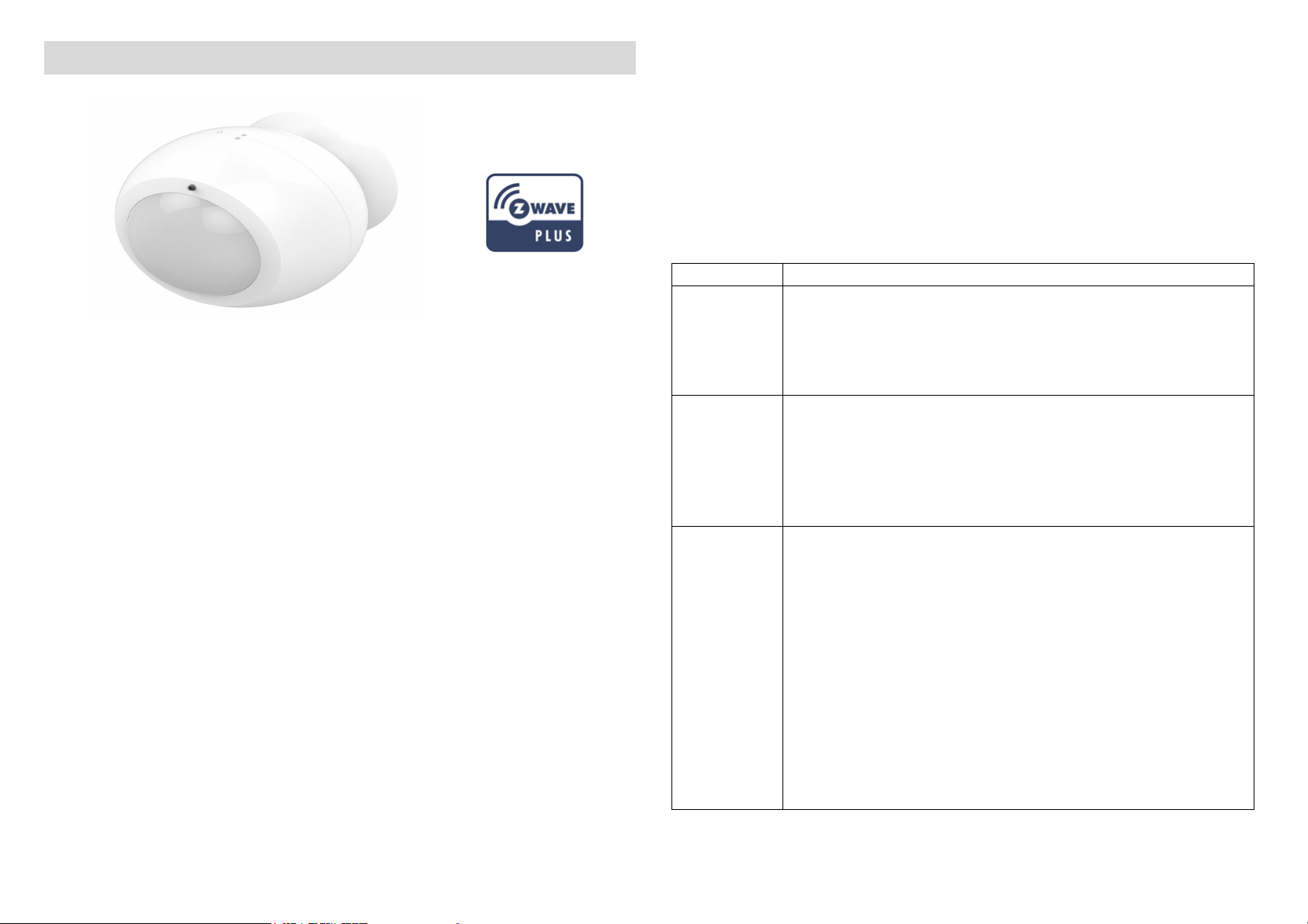
Z-Wave IR Extender PAR01
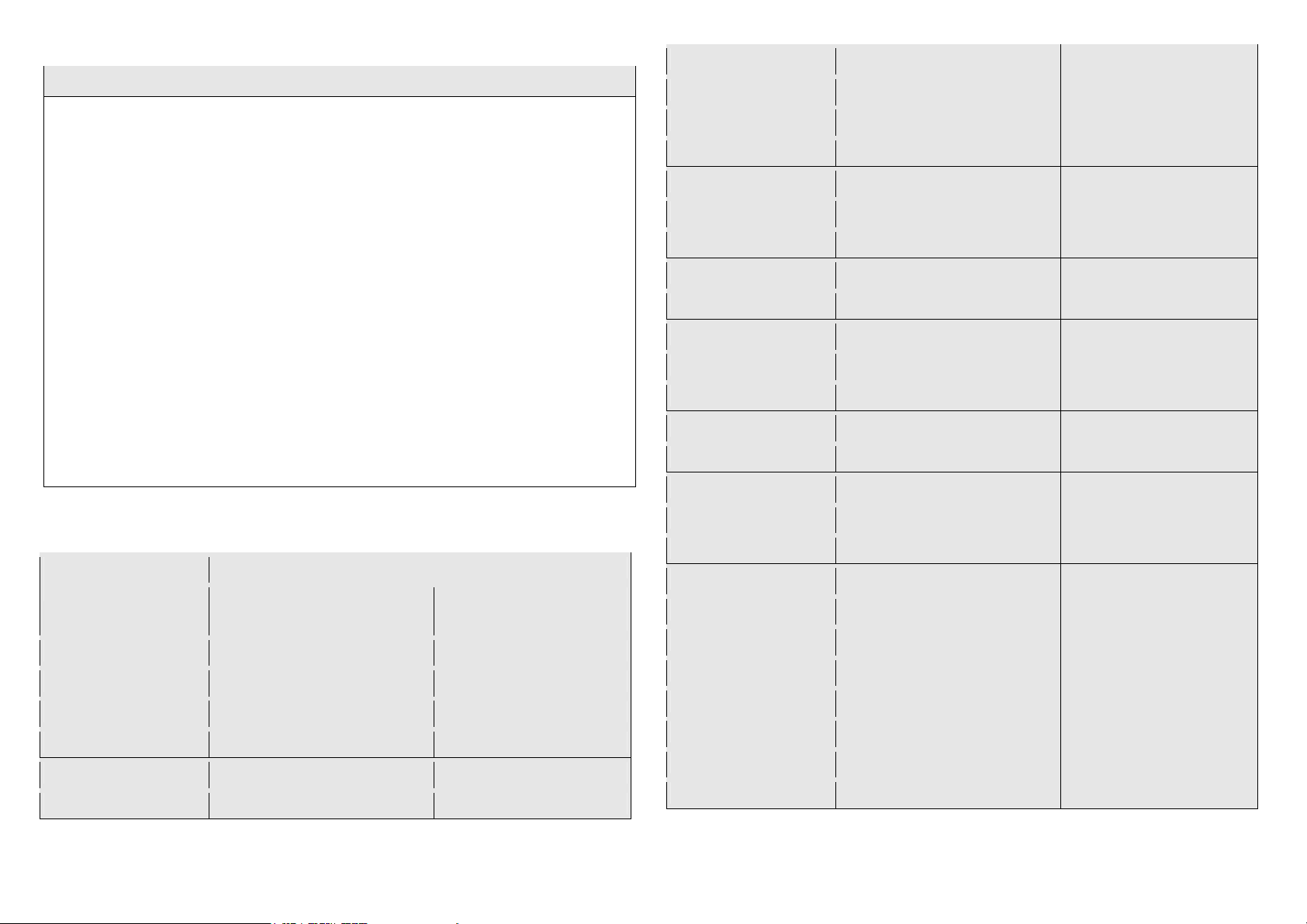
Function
Description
1. Ha
ve Z
-
Wave
TM
Controller entered add mode.
1. Have Z
-
Wave
TM
Controller entered remove mode.
Notice: Use this procedure only in the event that
PAR01, is a Z-Wave plus compliant Z-Wave-to-IR Bridge to control split
air conditioner by receiving Z-Wave command and translating to
Infrared command. With its comprehensive built-In and cloud-stored IR
database (library). PAR01 can control different
brands and models of air conditioners worldwide.
PAR01 is a security enabled Z-Wave plus device. A security Enabled
Z-Wave Plus Controller must be used in order to fully utilize the
product.
PAR01 is a Z-Wave slave device, it depends on gateway to setup
particular AC brand with correct IR code. Different gateway has
different user interface for setup.
This product can be included and operated in any Z-WaveTM network
with other Z-WaveTM certified devices from other manufacturers and/or
other applications. All non-battery operated nodes within the network
will act as repeaters regardless of vendor to increase reliability of the
network.
The device adopts the Z-WaveTM 500 series chip, when your Z-WaveTM
network system is all made by Z-WaveTM 500 series devices. The
network system will have the advantages as below.
Adding to Z-WaveTM Network
In the first time, activate the device through battery, then it can be
added into the Z-WaveTM network. First, make sure the primary
controller is in the add mode. And then power on the device. The
device will auto start the NWI (Network Wide Inclusion) mode. And it
should be added in 5 seconds. You will see the LED light ON one
second.
Add
Remove
Reset??
2. Press the add key in the casing three times
3. After add successful, the device will wake to
receive the setting command from Z-WaveTM
Controller about 20 seconds.
2. Press the add key in the casing three times
3. Hold down the central key, then press the top-right
key three times within 1.5 seconds to enter the
remove mode.Node ID has been excluded.
the primary controller is lost or otherwise
inoperable.
1. Hold down the central key, then press the top-right
key four times within 1.5 seconds and do not
release the top-right key in the 4th pressed, and the
LED will light ON.
Note: PSR03-C is reset by pressing panic key four
times within 1.5 seconds and do not release the topright key in the 4th pressed.
2. After 3 seconds the LED will turn OFF, after that
within 2 seconds, release the keys. If successful,
the LED will light ON one second. Otherwise, the
Page 2

LED will flash on
ce.
3. IDs are remove and all settings will reset to factory
Please consult your Gateway supplier for more detail.
•
Includin
g a node ID allocated by Z
-
Wave
TM
Controller means
default.
Normally, User can ignore this step during the setup.
PAR01 supports 1 association group
Association Group #1
Association Group #1 (max. 1 node) is default to
associate with the primary controller
(Gateway/Hub/Controller) for AC Master Status
Association
change report, refer to below for report details:
• Current Room Temperature (report in precision of
0.5°C or 1°F) (It will be according to Configuration
Parameter 39 setting to decide the trigger level)
• Current Battery Level (Only apply in Low Battery
Warning happened)
• Device Reset Locally Notification (Only report when
the AC Master has been triggered the RESET TO
DEFAULT)
“Add” or “Inclusion”. Excluding a node ID allocated by ZWaveTM Controller means “Remove” or “Exclusion”.
• Failed or success in including/excluding the node ID can be
viewed from Z-Wave
TM
Controller.
Notice 1: The device can not work normally in the first time. Please
make sure the battery is full before the first use.
Notice 2: Always RESET a Z-WaveTM device before trying to add it to a
Z-WaveTM network.
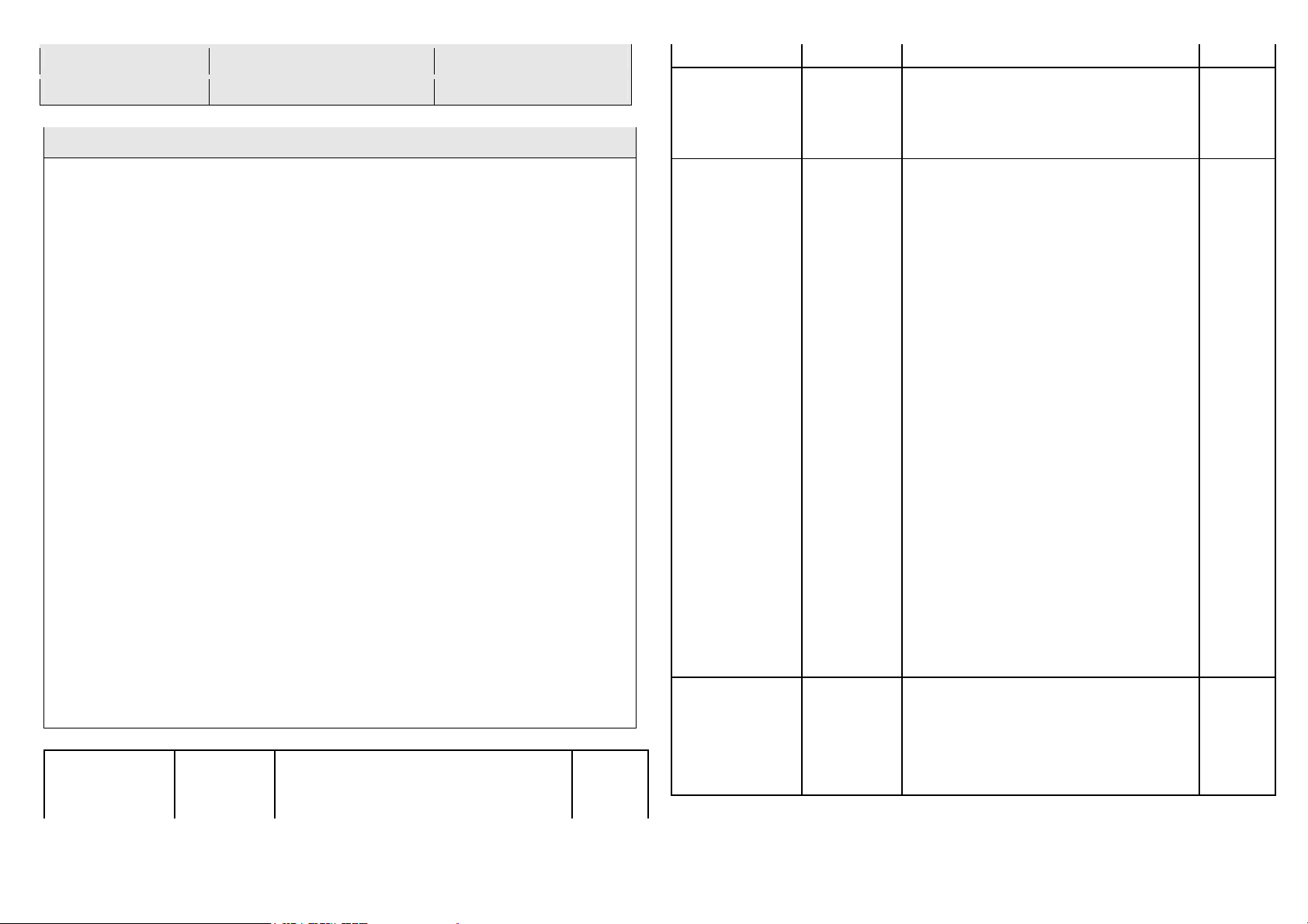
Get Started
Step 1 Apply Power to PAR01
• Open the PAR01 Casing
• InstallCR123 batteries
• PAR01 will detect the first applied power source to decide what
Z-Wave device role it will be in after included into the Z-Wave
gateway: battery= sleeping device (FLiRS mode).
• Once the PAR01 is included into a Z-Wave network, the working
mode (sleeping or awake) cannot be changed, unless it is excluded
and re-apply the power.
•PAR01 can be included and operated in any Z-Wave network
with other Z-Wave certified devices from other manufacturers
and/or other applications. All non-battery operated nodes within
the network will act as repeaters regardless of Vendor to increase
reliability of the network.
Step 2 Include PAR01 to a Z-Wave Gateway
Step Procedure / Description Status Indicator
1.Refer to your primary controller to enter into the Inclusion Mode or
Exclusion Mode
2.When it is prompted to enter it, please triple click the “PROG” button
within 1 second. Green Indicator flashes TWICE then stay off
Notes:
1. It is recommended to perform the Remove (Exclude) procedure
before performing
an Add (Include) procedure.
2. Red Indicator flashes TWICE then stay off to represent the Add /
Remove process
failed, please repeat the above step again.
Step 3 Setup Automatic Status Report Association to Gateway
•Please consult your Gateway supplier for more detail. Normally, User
can ignore this step during the setup.
Page 3

PAR01 supports 1 association group
Association Group #1
Association Group #1 (max. 1 node) is default to associate with the
primary controller (Gateway/Hub/Controller) for the Status
change report, refer to below for report details:
• Current Room Temperature (report in precision of 0.5°C or 1°F) (It
will be according to Configuration Parameter 39 setting to decide
the trigger level)
• Current Battery Level (Only apply in Low Battery Warning happened)
Step 4 Setup Air Conditioner IR code
• The UI of set up the IR code varies from different gateways. If
gateways have dedicated UI for the IR code setup please refer to the
gateway UI and ignore the below steps.
• If your gateway does not have dedicated UI for PAR01 code setup,
but support Z-Wave thermostat Command Class and Configuration
Command Class. You may refer to below steps to setup the IR code
using the configuration options in your gateway.
Important Information
• Different brand or model of air conditioner has different function.
For example, some air conditioner only support temperature set
from 18°C - 30°C, if user set 17°C on gateway, AC Master will not
respond.
• There are more than 1 code for each brand, some does not
support Heat, if User selected a code that does not support
Heat but Original air conditioner supports Heat Function, please
continue to try next code until the correct one is selected.
• You can record down your Device Code for future reference after
setting up the PAR01 correctly.
IR Code Learning
Step Procedure / Description Status Indicator
1.Refer to your primary controller user manual, enter to the browser
page that can input the Configuration parameter
2.Look up Below mapping table for learning, and decide the IR setting
you intend to learn next.
3.Open the Gateway’s Configuration Brower page input parameter
number “25” and parameter value (according to below Mapping Table),
then complete the Configuration process.
Then Green Indicator still turns ON for indicating the IR Code
Learning Start
4.Aim the Original Air Conditioner Remote at AC Master according to
below position within 1-3cm Press “Power ON“ button on the Original
Air Conditioner Remote.
If the Learning is failed, repeat Step 3 to step 4
To learn next IR code, repeat Step 2 to step 4.
Successful: Green Indicator flashes TWICE
Unsuccessful: Red Indicator flashes TWICE.
5.Once you finished the IR Code Learning,
please go to Configuration setting page on the Gateway browser and
input parameter number “27” and parameter value “000” to select the
dedicated AC code number “000” for learning.
Green Indicator flashes ONCE every time if receives a command
from Gateway
Page 4
Tips
• Make sure your Original Remote is
in Power OFF Status.
Parameter Value
Thermostat Command & IR Setting
Storage in Celsius Unit
Storage in Fahrenheit
0 OFF
OFF
1 ON(Resume)
ON(Resume)
2 17°C COOL
63°F C
OOL
3 18°C COOL
64°F COOL
4 19°C COOL
66°F or 67°F COOL
5 20°C COOL
68°F or 69°F COOL
6 21°C COOL
70°F or 71°F COOL
7 22°C COOL
72°F or 73°F COOL
8 23°C COOL
74°F or 75°F COOL
9 24°C COOL
76°F COOL
10 25°C COOL
77°F or 78°F COOL
11 26°C COOL
79°F
or 80°F COOL
12 27°C COOL
81°F or 82°F COOL
13 28°C COOL
83°F or 84°F COOL
14 29°C COOL
85°F COOL
15 30°C COOL
86°F COOL
16 17°C HEAT
63°F HEAT
17 18°C HEAT
64°F HEAT
18 19°C HEAT
66°F or 67°F HEAT
19 20°C HEAT
68°F or 69°F HEAT
20 21°C HEAT
70°F
or 71°F HEAT
21 22°C HEAT
72°F or 73°F HEAT
22 23°C HEAT
74°F or 75°F HEAT
23 24°C HEAT
76°F HEAT
24 25°C HEAT
77°F or 78°F HEAT
25 26°C HEAT
79°F or 80°F HEAT
26 27°C HEAT
81°F or 82°F HEAT
27 28°C HEAT
83°F or 84°F HEAT
28 29°C HEAT
85°F HEAT
29 30°C HEAT
86°F HEAT
30 DRY Mode
DRY Mode
• Make sure your Original Remote set FAN Speed to AUTO and FAN
SWING to AUTO/ON
• Press and Hold the Power Key on Original Remote UNTIL AC Master
indicate Successful or Not.
• User need at least Learn the OFF (Parameter Value 0), and one
Temperature Mode (Parameter Value 2 ~ 28) to complete the usage
model.
• Keep away from Incandescent Light or Direct Sunlight during
learning.
• Make sure IR Transmitter of your Original Remote alight with
learning diode of AC Master, you may also slight adjust closer or
further away the distance of two devices. Some of Remotes the
IR transmitter in hidden behind lens and may not installed center
of remote.
• Make sure the power is good on both devices, especially the
Original remote. Use Fresh Batteries in both devices recommended.
IR Learning Mapping Table (Parameter Number 25)
(Storage Location)
Unit
Page 5
31 AUTO Mode
AUTO Mode
32 FAN Mode
FAN MODE
Important Information
•After all learning completed, Us
er can go back to the
Parameter
Size
Default: 0x0000
Learn IR code
25 (0x19)
range: (0x0000 to 0x20)
2
refer to learning mapping table
Default: 0x00
range: 0 to 4 (0x00 to 0x04)
0(0x00) : Idle
- IR Channel is idle
1(0x0
1) : OK
- the last learning
2(0x02) : Learning
- PAR01
is busy
3(0x03) : Full
– All locations are being
was failed
Note:The status value 0x01 and 0x04
will be reset to 0x00 after
PAR01
receives a get command to this pa
-
rameter.
Set IR Code
number from
code library
control page on the gateway for normal operation.
• On the Gateway UI, User can only use the Temperature range
from the mapping table, OFF, ON(RESUME), COOL, HEAT, DRY
MODE, AUTO MODE and FAN MODE.
• If User only learnt ON(RESUME), OFF, or part of the settings
according to the above table, PAR01 will send the learnt data
to the Air Conditioner only. For example, User only learnt
ON(RESUME),OFF, 22°C COOL, 24°C HEAT, PAR01 will not send the
IR Data to Air Conditioner if User set 27°C Cool on the gateway.
• User can still use gateway to set up Scene and Schedule with
PAR01. For example, to have AC turn on at 23°C every day at
7am, 25°C at 11pm. Just make sure the set code is learnt.
• The learning mapping table is for split Air Conditioner, which Remote
Control is with LCD Display. For Window type Air Conditioner
(which Remote Control is without LCD Display), the mapping
table with temperatures do not apply, due to different type of IR
Control Protocol. However, User may still use OFF, ON(RESUME),
DRY, AUTO or FAN Key for Learning.
• (Because the POWER key on the Original Remote (without LCD
Display) is toggle, user can choose either ON key or OFF key to
learn Power key. After Learning is done, press once to turn on the
Air Conditioner if the Air Conditioner is OFF, press once to turn
OFF if the Air Conditioner is ON)
Check IR Code
Learning
Status
(Read Only)
26(0x1A)
opera
tion was completed
successfully
processing previous learning request
Used.
4(0x04) : The last learning request
1
Functions
Number
Parameter Value
( bytes)
27 (0x1B) Refer to Code Finder Webpage.
built-in
2
Page 6

in IR Emitter
Control
( If there have
two or more
Air Condition
-
ers with the
same code set
Default: 0xFF
that are used
0 or 255
in the same
32 (0x20)
(0x00 or 0xFF)
1
room, user
0(0x00): Disable
can disable
255(0xFF): Enable (Default)
the built
-
in IR
emitter and
use the exter
-
nal IR emitter
cable to
control each
air conditioner
Control Air
Default: 0x0
1
Conditioner
Range 0 to 1 (0x00 or 0x01)
function
1(0x01) : Swing Auto (Default)
= 0°C
1(0x01)
= 1°C
2(0x02)
= 2°C
Calibrate
3(0x03
) = 3°C
4(0x04)
= 4°C
temperature
37 (0x25)
5(0x05)
= 5°C
reading
255(0xFF) =
-
1°C
254(0xFE) =
-
2°C
253(0xFD) =
-
3°C
252(0xFC) =
-
4°C
251(0xFB) =
-
5°C
Temperature offset value.
= 0°C
1(0x01)
= 1°C
2(0x02)
= 2°C
Temperature offset value.
Set Built-
0(0x00)
0(0x00)
(Default)
(Default)
33 (0x21)
“SWING”
0(0x00) : Swing OFF
1
Page 7

0(0x00) = Disable AUTO report
func-
Report
Condition
30 (0x1E
By Room
Auto
report by the following time
5(0x05)
= 5 Hrs
tion (Default)
(for saving battery life)
Auto report if room temperature is
different from last report.
1(0x01) = 1°F (0.5°C)
2(0x02) = 2°F (1°C)
3(0x03) = 3°F (1.5°C)
4(0x04) = 4°F (2°C)
5(0x05) = 5°F (2.5°C)
6(0x06) = 6°F (3°C)
7(0x07) = 7°F (3.5°C)
Set Auto
Trigger
Temperature
Change
Set Auto
Report
Condition
By
Time Interval
34 (0x22)
8(0x08) = 8°F (4°C) 1
interval.
1(0x01) = 1 Hr
2(0x02) = 2 Hrs
3(0x03) = 3 Hrs
4(0x04) = 4 Hrs
1
6(0x06) = 6 Hrs
7(0x07) = 7 Hrs
8(0x08) = 8 Hrs (Default)
Note:
All the above Parameter Number and Value is in Hexadecimal
Numbering Format,
if the Gateway only support decimal numbering format, please change
it to decimal value accordingly.
Reset to Factory Default
Press and Hold “PROG” button for 3 seconds on AC Master, the
Green Indicator will light up. DO NOT Release the “PROG”
Button until Green Indicator flashes TWICE.
Z-WaveTM Notification
After the device adding to the network, it will wake-up once per day in
default. When it wake-up it will broadcast the “Wake Up Notification”
message to the network, and wake-up 10 seconds for receive the
setting commands.
To wake-up the device immediately, please hold down the program key,
and press the top-right key once.
Z-WaveTM Message Report
When the panic triggered, the device will report the trigger event and
also report the battery status.
Page 8

Activate the power
This marking indicates that this product should not be
* Battery Power Check
When any keys around the central key is pressed, the device will check
the battery power. If the power level is too low, the red LED will flash
once after pressing. Please charge the device through micro USB
immediately.
* NWI
When the device is activated, the device will check is it already adding
to the network? If doesn't, it will auto start the NWI mode. The LED
will flash in every second and continue 30 seconds. Until timeout or the
device successful to add by controller. Users can hold down the central
key, then press the top-right key three times within 1.5 seconds to
abort the NWI mode.
Over The Air (OTA) Firmware Update
The device support the Z-Wave firmware update via OTA.
Let the controller into the firmware update mode, and then wake up
the device to start the update.
After finish the firmware download, the LED will start flash in every 0.5
second. Wait the LED stop flash, the firmware update is succeeded.
Caution: Do not running the OTA when the battery is running low.
Spec
Power by Li 602025 battery.
Signal (Frequency):
868.40 MHz, 869.85 MHz(EU),
908.40 MHz, 916.00 MHz(US),
922~927 MHz(JP/TW),
921.40 MHz, 919.80 MHz(ANZ),
869.00 MHz(RU),
865.20 MHz(IN),
916.00 MHz(IL),
RF Maximum Power: +5dBm
Range:
Minimum 40 meters indoor, 100 meters outdoor line of sight.
Operating Temperature: 0oC ~ 40oC
For indoor use only.
Specifications subject to change without notice due to continuing
product improvement.
Disposal
disposed with other household wastes throughout the EU.
To prevent possible harm to the environment or human
health from uncontrolled waste disposal, recycle it
Company of License Holder:Philio Technology Corporation
Address of License Holder:8F., No.653-2, Zhongzheng Rd., Xinzhuang
responsibly to promote the sustainable reuse of material
resources. To return your used device, please use the
return and collection systems or contact the retailer where
the product was purchased. They can take this product for
environmental safe recycling.
Page 9

Dist., New Taipei City 24257, Taiwan(R.O.C)
ACMA
1092 986 605
ACSON
628 602 463
ACURA
94
AERMEC
429 90 606 395 292 18
AIDE 492
AIKIRA
174
AIRCON
1058 395 42 58 57
AIRWAVE
792
AIRWELL
276 670 598 433 432
AKAI 434
ALPIN
718 717 715 714 625 624
AMANA
836
AMCOR
716 668 665 664 663 662
AMERICOOL
430
AMVENT
811 46
APTON
513 839 525 524 523 522 521 520 519
517 516 515 514 508 67 40 518
ARIAGEL
507 13
ARISTON
40
AUCMA
414 413 412
AUX 407 591 585 1057 614 398 190 1190
1050 588 399 189 21 1091 1014
AZURE
424
BALLU
643
BEAVER
1080 386 383 370 184
BEKO
46
BENQ
1040
BESTECH
890 782 781
BGH 40
BLUE STAR
498 429 292 40
BLUERIDGE
1058 395
BOERKA
649 646 193 654
BOSCH
495
CARRIER
397 669 645 608 1066 1058 607 604 512
88 56 55 501 431 396 112 111 110
108 107 106 105 104 103 102 101 100
98 97 96 292 109 99
CELIERA
545
CENTURY
55
CHANG HONG
640 613 475 474 180 179 178 148 136 135
134 127 126 125 124 123 122 121 5
CHIGO
186 42 1004 574 193 547 58 57
CHIMEI
805 777 401 211
CHOFU
447 446 445 444 443 442 441 440 439
CHUANHUA
113 37
CHUNLAN
1008 1016 19 435 151 150
CKC 505
CLASSIC
46
Warning
Do not dispose of electrical appliances as unsorted municipal waste,
use separate collection facilities. Contact your local government for
information regarding the collection systems available. If electrical
appliances are disposed of in landfills or dumps, hazardous substances
can leak into the groundwater and get into the food chain, damaging
your health and well-being.
When replacing old appliances with new once, the retailer is legally
obligated to take back your old appliance for disposal at least for free
of charge.
Page 10

COAIRE
46
COMBINE
489
COMFEE
40
COMFORTAIRE
672 606 429 820 55 46
COMFORTSTAR
292 606 78 40 35
CONCORD
489
CONFORT MASTER
380
CONROWA
319 113 70 37
CONSUL
621 469 468
CONTINENTIAL EDISON
40
COOLINE
46
COOLRECH
4
COOLWEX
428 18
CORONA
288 1140 1138 1137 1132 1126 456 455 454 453
452 451 450 449 448
CRYSTAL
54
DAEWOO
70 40
DAIKIN
11 6
627 601 597 366 321 313 290 289
1189 1164 1121 1037 1034 1030 1026 829 786 394
367 324 1063 1007 887 602 26 1 1094 1075
978 971 876 875 861 608 511 374 373 325
261 211 163 162 32 30 2 384 270 269
268 267 266 265 264 29 353 349 345 344
343 33 31 543 357 354
DAITSU
788
DANTEX
841 797
DEER(SHUANGLU)
592 1047
DELCHI
40
DELONGHI
819 818 787 91 46 503 13
DEMIRDOKUM
42
186
DIAMANT
106
DIMSTAL
545
DOCTOR
846 771 756 722
DONGBAO
652 646 654
DUCTLESSAIRE
186 55
DURAMAXX
545
ECOAIR
429 42 18
ELCO
713 432
ELECISM
1011
ELECTRA
1165 433 432 467 466 465
ELECTROLUX
611 584 578 295 40 994 292 88 646 623
654 55 297
ELGIN
57
ELSONIC
1175
EMAILAIR
504 153 34
EUROPACE
1093 629 606 984 983 429 40
FAGOR
40
FANAIR
1058
FANWORLD
380
FEDDERS
812 764 762 729 276
FEILU
319 494
FERROLI
1058
FIRSTLINE
83
FORTRESS
639 40
FRESTEC(FRESTECH)
587 581 1056 1046
FRIEDRICH
832 783 606 540
FRIGIDAIRE
1058 1002 46 275 274 273
FRIGOLINE
88
FROST
567 566
FUJI ELECTRIC
1113
FUJIAIR
638 54
FUJIAIRE
542
FUJIMARU
567 527
Page 11

FUJITSU
671 1024 1021 821 204 1033 1032 1031 1029 1023
893 892 870 25 16 1081 1039 1025 1022 616
540 539 459 334 333 202 1090 853 852 335
227 206 205 203 201 200 199 161 160 159
158 34 27
FUJITSU GENERAL
671 1024 1021 821 204 1023 25 16 1025 1022
34 27
FUNAI
482 766 728 726
FUNIKI
580
GALANZ
537 381 277 86 1147 1082 193 488 473 83
70 4
GALLETTI
40
GE (GENERAL
40 637 292
GENERAL
671 1024 1021 821 204 1113 1023 25 16 1025
1022 1187 1186 57 34 27
GERMAN POOL
1019 1020 292 1185 1058 817
GIBSON
513 839 525 524 523 522 521 520 519 518
517 516 515 514 508 40
GORENJE
46 55
GREE
645 644 376 1058 823 672 395 292 18 429
15 659 658 656 606 508 195 155 154 69
GREENE
588
GSG 891
GUANGDA
319 113 37 20
GUQIAO
498
HAIER
1061 835 830 655 417 1003 999 836 406 256
75 657 535 257 210 209 208 207 198 197
172 156 77 76 23
HAMILTON DIGITAL
186
HAWRIN
894
HERAN
807 40 429 56 421 869 868 867 866 851
850 565 562 550 55
HESSTAR
380
HISENSE
975 828 382 80 12 10 427 410 68 9
405
HITACHI
600 599 418 403 291 1036 1035 1012 878 877
864 39 1173 1105 1065 1052 642 472 415 390
186 120 52 42 1178 974 973 879 865 436
391 375 263 262 260 259 258 255 53 51
50 339 299 298
HONEYWELL
833 980
HUABAO
1018 995 618 509
HUAGAO
1001
HUALING
193 547 476 70 56 37
HUIFENG
996 493 113
HYUNDAI
1125 479 1179 481 480
IATU 40
IDEMA
40
INVENTOR
292
INYAN(YINYAN)
1067 70
JDC 768 755 725
JINSONG
646 654
JINTNC
897
JOHSON
153
KANG LI
43
KAYSUN
40
KELON
12
411 409 489 487 486 485 143 14 13
KELVINATOR
87 46 17
KLIMAIRE
512 46 40
KLIMATAIR
767 757 744 724
KOLIN
810 776 534 533 532 531 530 529 206 44
KOMECO
40 88 46
KONKA
193 42 70
LENNOX
292 186 42 606 69 54 46 18 15 4
ELECTRIC)
Page 12

LEVANTE
46
LG 820 294 1111 832 817 648 615 464 91 17
82 81
LITTLE DUCK
770 765 740 739 738 737 736 720
LITTLE SWAN
653 650 649 646 193 654
LLOYD
186
LOREN
-
SEBO
844 760 759 751
MACRO
489
MAXE
1181 791 789 574 573 572 571 570 569 568
567 559 558 505 500
MAXXCOOL
545
MCQUAY
576 575 606 496 470 196
MEICO
41
MEITAV
714
MIDEA
589 579 40 972 512 56 55 54 46 78
79 48 113
MIDEA_TOSHIBA
48
MILLER
512 292 42 58 57 55 54 46 40
MIRAGE
69 18 15
MITSUBISHI
320 314 286 484 385 327 233 42 387 305
304 303 302 285 284 283 282 281 280 279
249 248 247 246 245 244 194 311 308 307
113
MITSUBISHI ELECTRIC
595 603 326 315 287 1184 1183 1182 1118 1064
1038 992 991 842 594 393 1177 1176 1100 541
528 498 484 392 371 240 239 238 236 235
234 232 231 230 229 228 193 70 37 1117
982 981 884 883 882 881 500 355 351 237
186 176 153 93 57 35 340 347
MITSUBISHI(HEAVY
346 322 319 317 316 278 1095 1084 574 568
356 329 243 36 1174 837 547 386 383 370
363 361 360 359 350 338 328 254 253 252
251 250 184 165 164 133 132 131 119 118
117 116 115 114 113 79 38 20 310 309
306
MRCOOL
512
MULTIAQUA
834
NATIONAL
402 872 401 369 211 420 404
NEC 170 169 168 167 166 152 148 147 146 142
141 140 139 138 137 136 135 134 130 129
128 127
NEO 186
NEOKA
1042
NEWCLIME
292
NORITZ
772 754
O GENERAL
25
OLIMPIA SPLENDID
40
OLIMPO
46
OLYMPUS
667 666
OSAKA
68
PANASONIC
674 673 583 323 293 211 47 1123 1122 1120
1119 1114 990 872 871 855 849 822 813 675
462 461 609 544 378 186 95 42 1171 1145
1006 854 502 491 490 437 389 379 372 368
365 242 241 191 185 183 92 65 64 63
62 61 362 337 336
PANDA
28
PEARL
548
PHILCO
778 41 40
PIONEER
380 70 46 40
PREMIUM
40
PRIDIOM
57
PROTON
790 569
INDUSTRIES)
Page 13

QLIMA
40
QUIETSIDE
1058 186 42
RAMSOND
545
RASONIC
1116 1114 394
RECCO
538
REETECH
40
REMKO
40
RENFOSS
806 40 889 1180 568 563 551
RIELLO
506
RIEWITEC
57
ROLBIT ELECTRONIC
719
ROLSEN
582
ROWA
651 626 619
RYOBISHI
1112
SABRO
774 769 763 727
SAGA
714 712 711 710 709 708 707 706 705 704
703 702 701 700 699 698 697 696 695 694
693 692 691 690 689 688 687 686 685 684
683 682 681 680 679 678 677 676 661 660
659 658 657 656
SAIJO
-
DENKI
742 741 721
SAMPO
1060 808 804 863 862 848 847 1041 422 569
562 561 556 555 554 552 550 549
SAMSUNG
590 510 301 300 1124 634 633 632 631 630
612 477 49 1169 1000 998 425 84 74 73
1148 985 888 438 171 149
SANSUI
735 730 378
SANYO
586 46 1027 849 609 218 1141 1136 1135 1134
1133 1028 874 860 536 478 187 170 169 168
167 166 152 148 147 146 142 141 140 139
138 137 136 135 134 130 129 128 127 60
59 48 45
SASUKI
773 758 750
SAUNIER DUVAL
18 40
SCHNEIDER ELECTRIC
42
SENVILLE
512 78 55
SHANGLING
70
SHARP
809 816 815 636 318 1168 623 458 426 388
364 90 1170 1167 1127 840 352 341 217 216
215 214 213 212 192 157 145 144 143 8
66 7
SHINCO
85 22
SHINING
70
SHUAIKANG
582
SIEMENS
46
SIMON
-
AIRE 608
SKG 989
SLICK
714
SMARTECH
218
SOLEUS
395 380 18
SOVA
845 753 752
SPRINGER
88
SUPER GENERAL
57
SURREY
512 55
SWIFT
784
SYNCO
735 734 733 732 731
TADIRAN
40
843 749 748 747 746 745 471 54 48
46
TAKADA
1014
TATUNG
896 895 527 526
TCL 548 545 434 380 193 547 546 24
TECO
803 859 858 857 856 513 48 508 423 839
525 524 523 522 521 520 519 518 517 516
515 514 40
Page 14

TONAL
188
TOPPING
802 564 560 557 553
TORNADO
40 48 46
TOSHIBA
814 993 177 460 457 186 358 342 332 331
330 226 225 224 223 222 221 220 182 181
175 71 56 312 219
TOSHIBA CARRIER
814 177 182
TOSOT
292
TOTALINE
621
TOYACHII
574
TOYO
42
TOYO COOL
42
TOYOAIRE
380
TRANE
292 838 174 173 69 3
UNI-AIR 743 723
VAILLANT
40
VESTEL
976
VIDEOCON
994 186 647
VIVAX
292
VOLTAS
641 409 377 46 5 4
VORTEX
598
WANBAO
1083 319
WEILI
582
WESTINGHOUSE
46
419
WESTPOINT
88
WHIRLPOOL
775 610 596 593 489 271 1115 1076 1112 977
416 408 272 211 13
WHITE
-
1172
WINIA
766 728
XILENG
150
YAIR 1059 1013
YOAU
817
YORK
56
830 827 826 825 824 637 635 617 40
1188 1166 613 608 606 292 186 18 979 978
831 470 296 89 78 55 15
YUETU
577 70
ZAMIL
46
ZANUSSI
429 186 40
ZENITHAIR
46
ZHONGYI
622
WESTINGHOUSE
 Loading...