

ElDorado Advantage, AEROTECH, AEROLITE, AEROELITE Operator's Manual
ADVANTAGE
OPERATOR’S MANUAL

CONTENTS
01 INTRODUCTION
Welcome 4
Drunk Driving 5
Distracted Driving 5
Preventive Maintenance 5
Warranty Statement 5
Vehicle Certification Labels 6
Vehicle Emissions 6
California Proposition 65 7
Serial Number 8
Warranty Service 8
Vehicle Identification Number 9
Reporting Safety Defects 89
Symbols 4
02 INTERIOR
Floor Plans 11
Emergency Equipment 12
03 DRIVER’S AREA
Cab Area 13
Vehicle Dashboard 13
Control Console 13
Control Console Switch Symbols 88
Drivers Mirror 13
Backup Assist 13
Visor Mount 14
Buswatch 14
Interlock 14
Fast Idle 14
Ramp Interlock 15
Radio 15
Gauges 15
Climate Control 15
Reverse Alarm 16
PA System 16
Defrost Fan 16
Farebox Vault 16
Destination Sign 17
Stop Request 17
Emergency Reflector Kit 18
Hills & Obstructions 18
Setup Reflector Kit 19
Jumper Cables 20
Changing a Flat Tire 20
Towing Procedures 21
Vehicle Systems Safety Checks 23
Cargo Storage 25
Driving on Snow & Ice 26
Rocking the Vehicle 26
04 DOORS & WINDOWS
Doors 27
Key Locks 27
Chassis Cab Door 27
Passenger Entry Door 27
Hinges 27
Door Actuator Cover 28
Door Seals 28
Door Alignment 28
Door Leaf Adjustment 29
Gas Shocks 30
Paratransit Doors 31
Periodic Testing of Door System 31
Door Troubleshooting 31
Lift Terminology 32
Paratransit Operation 32
Mobility Lift 33
Pendant Control 34
Lift Power On/Off 34
Loading Ramp Passengers 35
Windows 36
Sliding Windows 36
Egress Windows 37
Window Operation 37
Egress Window Maintenance 37
Plug Windows 38
Emergency Hatch 39
Venting The Hatch 40
05 SEATING
Seat Options 41
Driver’s Seating 41
Passenger Seating 41
Seat Maintenance 41
Removing Passenger Seats 42
Seat Restraints 45
Seatbelt Maintenance 45
Seat & Seat Belt Checklist 45
Wheelchair Tie-Down & Occupant
Restraint System 46
06 FLOORING
Flooring 47
2

CONTENTS
Rubber Flooring 47
Floor Maintenance 47
07 INTERIOR FIXTURES
Walls & Ceiling 49
Stanchions 49
Stanchions Maintenance 49
Modesty Panels 49
Panel Maintenance 50
Cab Area Trim 50
Trim Maintenance 50
Rails & Safety Handles 50
08 ELECTRICAL
Electrical 51
Power Distribution Center 52
Wiring Harness 53
Electrical System Repair 53
Blunt-Cut Wires 54
Ground to Frame 55
Rear Axle Connection 55
Exterior Lighting 55
Front Clearance Lights 55
Rear Clearance Lights 56
Replacing Clearance Lights 56
Side Marker Lights 56
Interior Lighting 57
Replacing Courtesy Lights 58
Replacing Speakers 58
09 EXTERIOR
Cleaning Exterior 59
Exterior Sealant 60
Composite Exterior 61
Waxing/Compounding 61
Discoloration Removal 61
Repair Minor Fiberglass Damage 61
Standard Formulations 62
To Repair Minor Surface Cracks 62
To Repair Larger Surface Cracks 62
Aluminum Exterior 63
Waxing/Compounding 63
Discoloration Removal 63
Repairing Aluminum Exterior 63
To Repair Scratches In Paint 63
To Repair Dents Or Cuts 63
Undercoat/Primer 63
10 CHASSIS
Chassis 64
Lubrication 64
Filters 64
Brake Retarder 64
Fuels 65
Fuel Filling 65
11 WHEELS & TIRES
Tires & Wheels 66
Mud Flaps 67
Changing a Flat Tire 67
12 HVAC
HVAC Options 68
Heater Shut-Off 69
HVAC Drain Hoses 69
HVAC Maintenance 69
13 MAINTENANCE CHECKLISTS
Bus Maintenance 70
Operators Pay Attention 70
Pre-Trip Inspection 71
Pre-Trip Checklist 71
14 TRAILER TOWING 87
15 VEHICLE LOADING 87
Weights & Loading 87
SERVICE LOG 90
MAINTENANCE SCHEDULES
Daily 80
Weekly 83
Monthly 83
Semi-Annual 84
Annual 84
Cyclical 84
Learn More About Rev Group 89
3

01 INTRODUCTION
SYMBOLS
i CAUTION, WARNING, IMPORTANT
NOTABLE INFORMATION
u PROCEDURES & ACTION ITEMS
CAUTION means if the precaution is not
taken, it may cause minor or moderate
injury or damage to the bus.
WARNING means if the warning is not
heeded, it can cause death or serious injury
or damage to the bus.
IMPORTANT means if the precaution is not
taken, damage or injury could occur.
WELCOME
Thank you for purchasing an ElDorado
Advantage bus. ElDorado`s goal is to
provide its customers with vehicles
that reflect the highest standards of
quality, safety and value available in
the small and mid-sized bus industry.
Our products are supported by a
nationwide sales and service dealer
network and a customer service staff
dedicated to serving your needs.
Our customer service has made us
the industry leader and we strive to
maintain that position. A safe and
cautious driver knows the bus, follows
safe operation rules and performs
routine maintenance. This operation
and maintenance manual includes both
general and specific information for
the operation and care of your new
Advantage bus.
Competent and proper maintenance
and repair are important to the safe
and reliable operation of all buses. The
bus is a highly sophisticated piece of
equipment. Therefore; always use genuine parts, available through your local
dealer when servicing. Inferior, incorrect or mismatched parts may result
in bus malfunction, damage or even
personal injury. Becoming familiar with
your bus is the first step to providing
your passengers with a safe and enjoyable ride. While this manual is not a
substitute for common sense and cautious operation, it does offer guidelines
to help make the driver’s job easier
and as trouble-free as possible. Please
keep the manual in an accessible place
within your bus for easy reference.
4
01 INTRODUCTION
This manual may describe products features
and options that may not be on your vehicle.
Contact Advantage or your local dealership for
options available for your vehicle.
DRUNK DRIVING
Drinking and driving is considered very
dangerous. Your reflexes, perceptions,
attentiveness and judgment can be
affected by even a small amount of
alcohol. If you drive after drinking
alcohol you could have a serious or
fatal collision, do not drink and drive.
DISTRACTED DRIVING
Driving while distracted can result in
loss of vehicle control, crash and injury.
We strongly recommend that you
use extreme caution when using any
device that may take your focus off the
road. Your primary responsibilty is the
safe operation of your vehilce. Make
sure you are aware of all applicable
local laws that may affect the use of
electronic devices while driving.
PREVENTIVE
MAINTENANCE
Preventive Maintenance (PM)
is a systematic approach to the
inspection, repair, and maintenance
of your vehicle. Through preventive
maintenance vehicles are maintained
in such a way that defects are
prevented, avoiding vehicle breakdown
and/or out-of-service conditions.
Preventive maintenance can reduce
long-term damage and costly
repair of your vehicle, extending
the service life of your vehicle.
Preventive maintenance is essential
to the safe operation of your motor
vehicle, keeping your vehicle on the
road. Maintenance schedules are
provided in your Operator`s Manual.
ElDorado recommends following these
recommended maintenance schedules,
as the processing of warranty
claims may be affected. ElDorado
recommends use of the Service Log
contained within this Operator`s
Manual to record preventive
maintenance and repairs performed.
WARRANTY STATEMENT
To access the warranty statement
please scan the QR code.
5

01 INTRODUCTION
INCOMPLETE VEHICLE MFD. BY FORD MOTOR COMPANY
WITH TIRES
GVWR:
REAR
WITH
16x 6. 0K
AT 550 k Pa / 80 PSI COLD
TIRES
RIMS
DUAL
T
LT225 / 75R 16E 115/ 112R
GAWR:
4355 KG ( 9600 LB )
6577 KG ( 14500 LB )
RIMS
AT
VIN:
1FDFE4FS4HDC33553
LT225/75R16E 115/112R
16x6.0K
520 kPa / 75 PSI COLD
DATE:
FRONT
2268 KG ( 5000 LB)
12/16
GAWR
EXT PNT:
Equipped with the Ford
Shuttle Bus Prep Pkg
158
INT TR
XE
MADE IN U.S.A.
WB
F
83
P
XXBB
ULN
5U5A - 3520472 - AA
TP / PS R
RC: 86 DS0:
AXLE TR SPR
YZ
VEHICLE SAFETY
STANDARD CERTIFICATION
LABELS
The Vehicle Certification Labels are
attached to either the hinge pillar,
end of driver door or the door latch
post of the door edge that meets the
door latch post next to the drivers
seating position. The labels contain
the name of the manufacturer, the
month and year of manufacture,
the certification statement, and the
Vehicle Identification Number (VIN).
The labels also contain Gross Vehicle
Weight Rating (GVWR), Gross Axle
Weight Rating (GAWR), and information
codes for additional vehicle data, (U.S.).
VEHICLE EMISSIONS
INFORMATION
Emissions information appears on
the VECI decal which is located on or
near the engine. This decal identifies
engine displacement and also provides
certain tune-up specifications.
Illustration: Vehicle Emissions Label
(Ford Motor Company Decal Shown)
Illustration: Location Of Safety Certification Label
6
01 INTRODUCTION
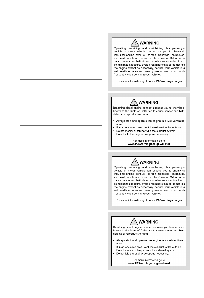
CALIFORNIA
PROPOSITION 65
Some constituents of engine exhaust,
certain vehicle components, certain
products of component wear contain
or emit chemicals known to cause
cancer and birth defects or other
reproductive harm.
Battery posts, terminals and related
accessories contain lead and lead
compunds, chemicals known to the
State of California to cause cancer
and reproductive harm. Batteries also
contain other chemicals known to the
State of California to cause cancer.
Wash your hands after handling.
7
01 INTRODUCTION
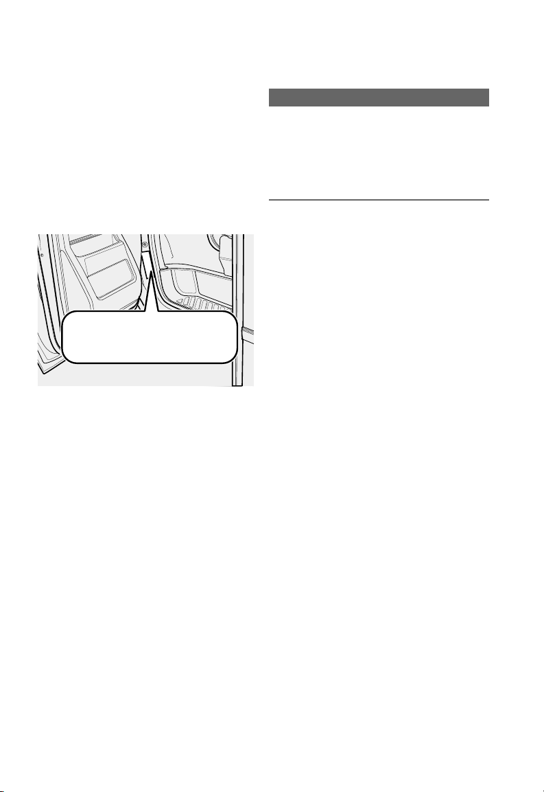
SERIAL NUMBER
The Advantage serial number is
different from the vehicle identification
number (VIN). The Advantage serial
number is located on a decal on the
driver’s door frame and is used by
the factory to identify the bus and its
options. Please refer to this number
when calling your dealer or the factory
with questions.
ElDORADO NATIONAL (KANSAS), INC.
MFD BY:
GAWR FRT GAWR INT GAWR RR
GVWR
6577KG (14500LB) 2268KG (5000LB) 4355KG (9600LB)
TIRE SIZE
AXLE
LT225/75R16 E
FRT
INT
LT225/75R16 E
RR
THIS VEHICLE CONFORMS TO ALL APPLICABLE FEDERAL MOTOR
VEHICLE SAFETY STANDARDS IN EFFECT IN 03/2017
VIN:
1FDFE4FS4HDC33553
MOD:
260 WORLD TRANS
RIM
16X6.0K
16X6.0K
TYPE:
SER:
(NOT SCHOOL BUS)
BUS
EFRSW260MH0000009
Illustration: Advantage Serial Number Location
DATE: 03/2017
PRESSURE
(COLD)
515KPA (75PSI)
550KPA (80PSI) (DUAL)
WARRANTY SERVICE
Please call your local dealer for parts
and service information or to purchase
parts. Please provide the last five (5)
digits of the Advantage serial number,
(located on a decal on the driver’s
door frame), when calling for parts
and service information. This number
is used by dealers and the factory
to locate parts information for your
particular bus.
For service, parts and product information,
please contact our REV Bus Business Support
Center at 800-955-9086.
The information contained in this
publication was accurate at the time of its
creation. Advantage and its suppliers reserve
the right to change the designs, specifications
or equipment at any time without notice
or obligation in the process of continuous
development.
i IMPORTANT
DRIVERS AND MAINTENANCE
PERSONNEL ARE ADVISED TO READ
THE MANUAL CAREFULLY. FAILURE TO
FOLLOW CERTAIN INSTRUCTIONS MAY
VOID MANUFACTURER’S WARRANTIES
AND/OR AFFECT PASSENGER SAFETY.
8

01 INTRODUCTION
Typical VIN No. 1 FM 5 K8 F 8 0 G G A69101
1-3 9 10 114-8 12-17
Position 1-3 World Manufacturer Identifier
Position 4-8 Line, Model, Body, Engine
Position 9 Check Digit
Position 10 Model Year
Position 11 Assembly Plant
Position 12-17 Sequential Number
VEHICLE IDENTIFICATION
NUMBER (VIN)
A seventeen digit combination of
numbers and letters form the Vehicle
Identification Number (VIN). The VIN is
stamped on a metal tab that is riveted
to the instrument panel close to the
windshield on the driver’s side. The VIN
number is also found on the Vehicle
Safety Certification Label. By looking
at the seventeen digit VIN number, a
variety of information about the vehicle can be determined. The first three
digits identify the manufacturer and
the vehicle make and type. The fourth
digit determines the brake system.
Digits five, six, and seven identify the
model or line, series chassis, and cab
or body type. The eighth digit points
out the particular engine found in the
vehicle. Digit nine is the VIN check dig-
it. The tenth digit identifies the model
year of the vehicle. The eleventh digit
determines the assembly plant. Digits
twelve through seventeen make up the
sequential serial and warranty number.
Digit twelve uses the letter “A” until
the production or sequence of 99,999
units is reached. Letter “B” then
becomes “C” for the next production
sequence of vehicles.
Example: (VIN) Number Positions
9

01 INTRODUCTION
POSITION 1
The first letter or number of the VIN denotes world region where the vehicle was
manufactured.
POSITION 2
The second letter or number, in combination with the first letter or number in the
VIN, tells you in what country the car or truck was manufactured.
POSITION 3
The third number or letter is used by the vehicle manufacturer to identify what
kind of vehicle it is: car, (truck, bus etc).
Each vehicle maker uses unique codes for this designation.
POSITIONS 4 5 6 7 8
Vehicle Descriptor Section (VDS)
Letters and numbers in positions 4 through 9 is the Vehicle Descriptor Section.
Each position describes the vehicle model, engine type, body and style, combined
to represent detailed information about the vehicle.
POSITION 9
This is the VIN Check Digit, which can be used to figure out if the VIN is correct.
POSITION 10
The 10th letter or number of the VIN tells you the model year of the vehicle. This
may be different from when it was actually manufactured, many automobile
manufacturers start to produce next years model this year.
If the 7th VIN position is a letter, then your vehicle is made in 2010 through 2039.
If the 7th VIN is a number, then your vehicle is made prior to 2010.
POSITIONS 11 12 13 14 15 16 17
Auto manufacturers enter unique information about the particular vehicle
the VIN belongs. The name of the assembly plant, extra vehicle options, and a
Production Sequence Number.
10
02 INTERIOR
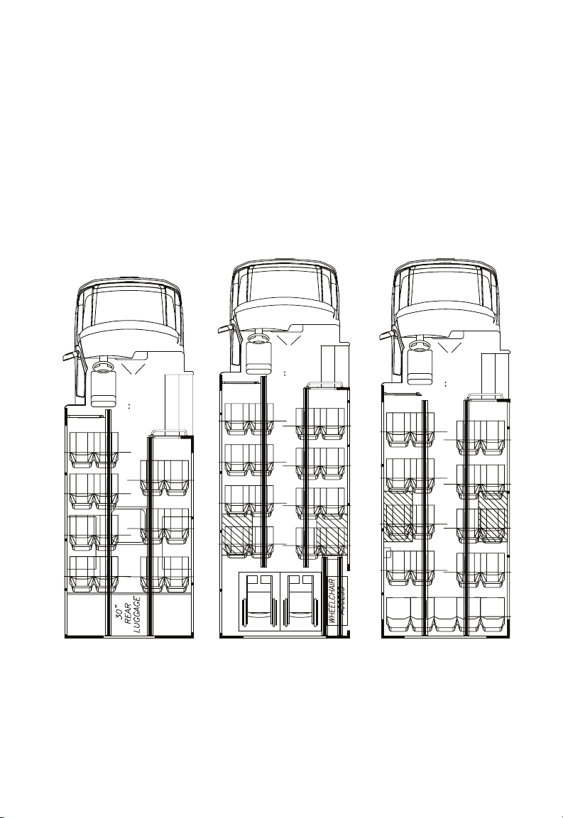
FLOOR PLANS
The Advantage offers a variety of
interior floor plans and options. This
manual includes most of the general
information which is common across
all bus platforms, but your bus may
differ in configuration and options. For
more information about your bus’s
specific options you may need to refer
to the users manuals specific to the
equipment not covered here.
Please refer to the various information
packets which were delivered with the
bus. You can also contact customer
support to get information about your
bus.
For service, parts and product information,
please contact our REV Bus Business Support
Center at 800-955-9086.
Sample floor plan:
14 passenger layout with
rear luggage
Sample floor plan:
16 passenger layout with
2 wheelchair
11
Sample floor plan:
21 passenger layout
02 INTERIOR
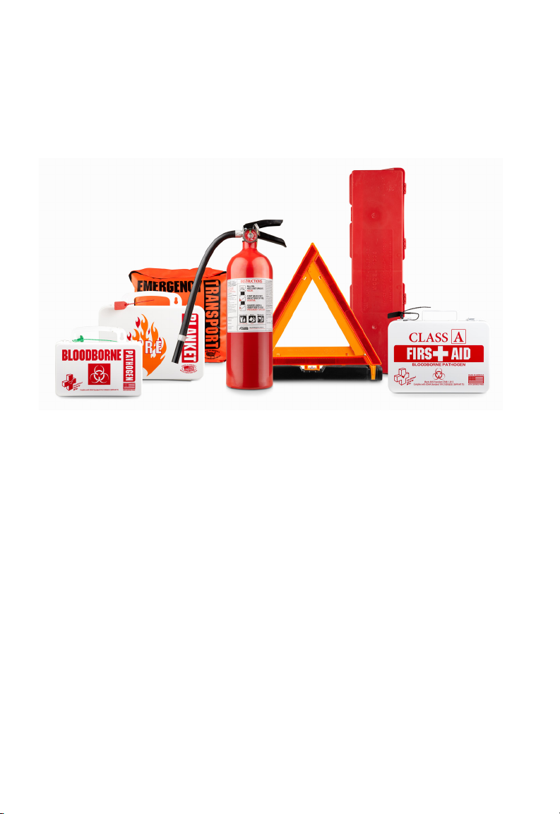
EMERGENCY EQUIPMENT
Your bus may or may not include the
following pieces of safety equipment:
Fire Extinguisher - Emergency
Image: Sample Of Safety Equipment Commonly Equipped On Advantage Buses
ADDITIONAL INFORMATION
Fire Extinguisher 5LB (Standard).
Visit: kidde.com
Fire Extinguisher 10LB (Option).
Visit: amerex-fire.com
Reflector Kit #449
Visit: lavanture.com
Body Fluid Clean-Up Kit
Visit: certifiedsafetymfg.com
Emergency Transport Blanket
Visit: certifiedsafetymfg.com
Deluxe Blood-Borne Pathogen Kit
Visit: certifiedsafetymfg.com
Transport Blanket - Fire Blanket -
Reflector Kit - CPR Kit And First Aid Kit
-Body Fluid Clean-Up Kit.
CPR and First Aid Kit
Visit: certifiedsafetymfg.com
CPR and First Aid Kit in Metal Case
Visit: certifiedsafetymfg.com
Fire Blanket 16PW 36” x 60”
Visit: certifiedsafetymfg.com
First Aid Kit 160 Unit -Calif-
Visit: certifiedsafetymfg.com
First Aid Kit #105
Visit: certifiedsafetymfg.com
12
03 DRIVER’S AREA
CAB AREA
The driver operates the bus from the
Cab Area where the driver can control
many systems: passenger lighting sound system - environmental controls
rpm
x1000
OK
SET+
CAN
RES
AIRBAG
SET-
Illustration: Driver’s Area
60
100
80
•
•
120
•
•
40
•
•
60
•
•
•
40
•
•
20
•
20
•
MODE
VOL/SEL
ST-4000
REI
WEATHER BAND
MP3/WMA
8
14
•
•
•
•
•
•
•
12
DISP
BAND
SCAN
FOLDER
APS
•
AUX 1
SD
•MENU
RPT INT
ROM
1
6
2
3 4
5
2
1
3
T/H
P
R
N
D
M
A/C
0
4
12V
AC
DOOR AJA R
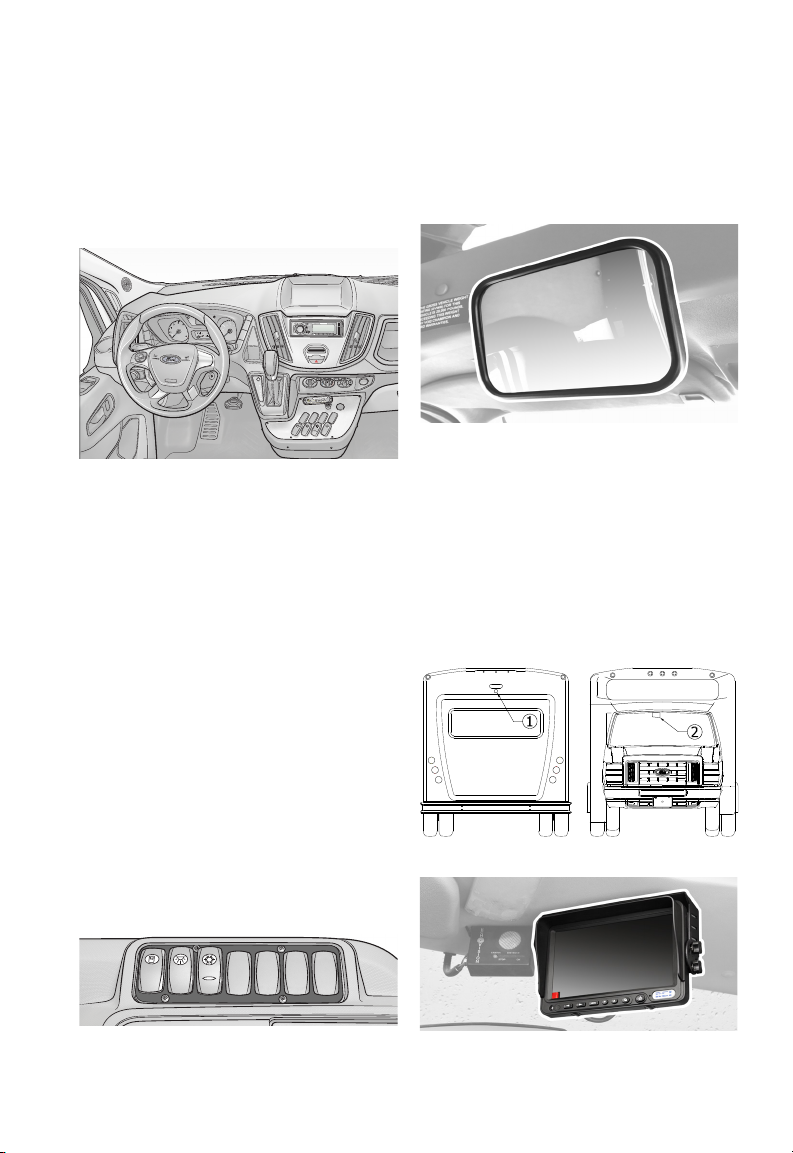
VEHICLE DASHBOARD
Details on vehicle dashboard instrumentation, steering, and other standard chassis controls are covered in
the chassis manufacturers manual
included with your bus. Please read
them thoroughly to become familiar
with the vehicle’s dashboard before
operating the vehicle. Vehicle dashboard options specific to your bus are
discussed in this manual.
CONTROL CONSOLE
The control console allows the driver
to control most of the electrical components of the bus. The specially
designed control panel is console
mounted to the right of the driver’s
seat and is within easy reach and clear
view of the driver. All controls are
labeled for easy reference. See page
88.
DRIVER’S MIRROR
If equipped, the driver’s mirror is
typically installed near the drivers sun
visor.
Image: Driver’s 6x16 Mirror
BACKUP ASSIST
CAMERA & MONITOR
If equipped, the backup assist camera
is located on the rear of the bus
exterior, typically installed in the center,
just below the 3rd brake light . The
driver’s 7” monitor is installed above
the dashboard to the right of the rear-
view mirror .
Illustration: Camera And Monitor Locations
Illustration: Driver’s Area - Control Console
Image: 7” Monitor
13
03 DRIVER’S AREA
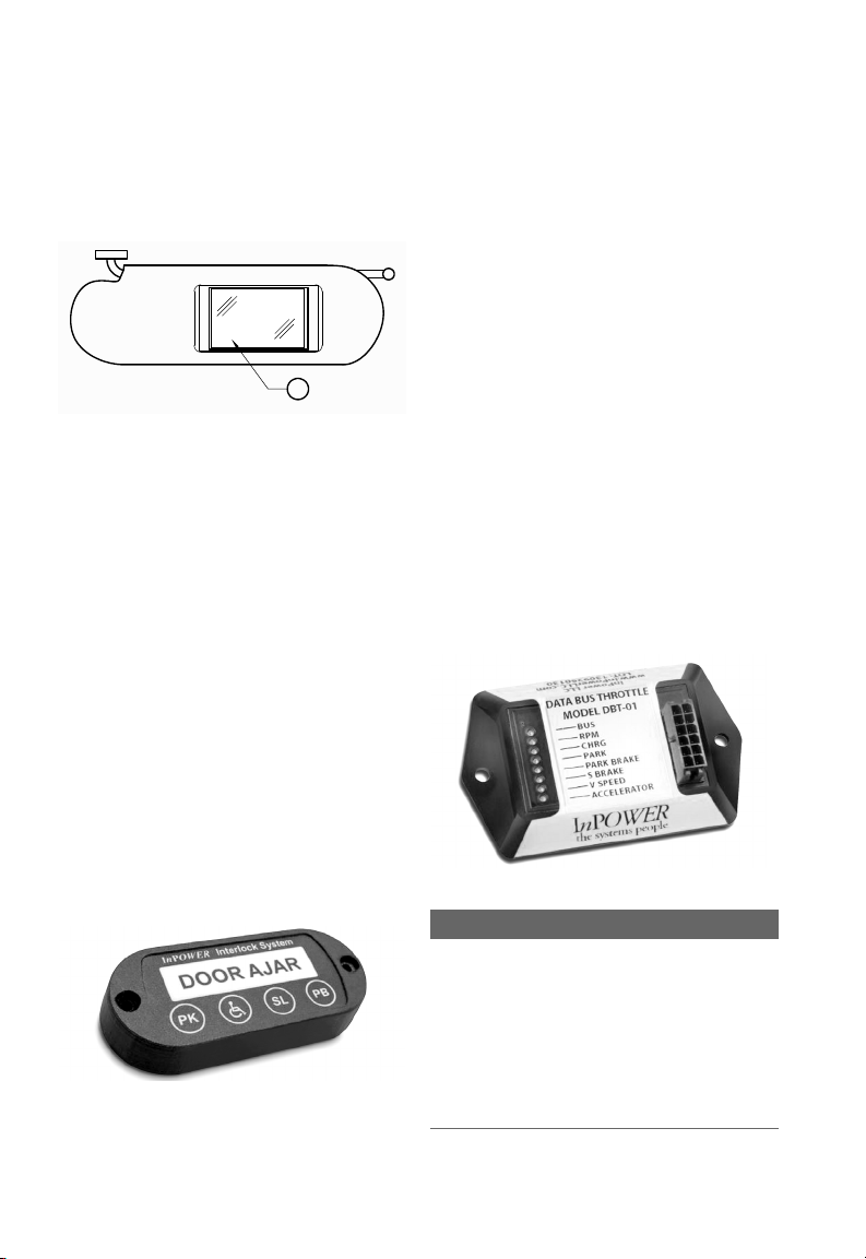
VISOR MOUNT
If equipped, the rear-observation
monitor could be mounted to the
Sun-Visor.
1
Illustration: Sun-Visor Rear Observation Monitor
Mount
BUSWATCH
If equipped, the Buswatch system can
connect multiple cameras to a DVR for
interior and exterior views.
INTERLOCK (InPower)
The interlock system provides inputs
from the platform lift door switch
and three other door switches, (Door
1 Switch, Door 2 Switch and Door 3
Switch). Anytime Door Switches 1, 2 or
3 are activated, (door not fully closed),
the DOOR AJAR display indicator
will flash and the shift lock will be
set. Anytime the Lift Door Switch is
activated, (door not fully closed), the
DOOR AJAR display indicator will flash
and the shift lock will be set. When in
PARK, with the parking brake set, the
Lift Enable will be set allowing the
platform lift to be operated.
Image: InPower Interlock
FAST IDLE
Fast Idle, (InPower shown), when
InPower’s Green Charge is activated,
the engine idle is raised to 900
RPM. It then gradually raises the
engine speed from 900 RPM to the
minimum speed necessary to charge
the batteries. Once the batteries are
charged, the Green Charge mode will
hold the engine idle at the minimum
RPM necessary to maintain the
charge, maximizing fuel economy
and minimizing emissions. On models
with the On/Off Charge Protect mode,
the engine is cycled between 900
and 1500 RPM as needed to keep the
battery charged. The preset modes
will elevate the engine to pre-adjusted
RPM. On standard models and most
custom models, the preset mode
values can be field adjusted. Some
custom models may have the field
adjustable feature locked out.
Image: InPower Fast Idle
i CAUTION
THIS ELECTRONIC THROTTLE PRODUCT
HAS BEEN DESIGNED AND MANUFACTURED
TO MEET THE INTENDED APPLICATION
REQUIREMENTS AND SPECIFICATIONS. ANY
MODIFICATIONS TO THE PRODUCT OR TO
THE INSTALLATION PROCEDURE CAN BE
DANGEROUS AND WILL VOID INPOWER’S
WARRANTY.
14

03 DRIVER’S AREA
ADVANCED FAST IDLE
INTELLIGENT LIFTINTERLOCK SYSTEM
LIFT POWER PARKING BREAK PARK SHIFT LOCK
SCAN
BAND
INTERLOCK (Intermotive)
Powered operation of your lift is
regulated by safety interlocks. These
interlocks mandate the following
conditions be met for the lift to
operate:
1. Transmission is in PARK (P).
2. Apply parking brake.
3. Open entry door.
These conditions are indicated to the
driver on an indicator panel located
near the gauge cluster. The most
common version is shown in the image.
The park, parking brake, and lift door
open indicators will glow red when
each of these conditions is proper. The
“shift lock” indicator will glow red to
indicate the shift lever has been locked
in the park position. With all four of
those indicators glowing red, the lift
can receive power.
LIFT DOOR/ AUX DOOR
DOOR AJAR
INTERMOTIVE
GAUGES
If equipped, the control panel
may include gauges to inform the
driver of the many system which
require monitoring. Common gauges
include hour-meter, voltmeter and
Temperature Gauge.
F
260
200
300
12
14
HOURS
0
0
5
0
6
6
VDO
10
VDO
Illustration: Common Gauges
120
120
16
90
150
C
VDO
CLIMATE CONTROL
Cab area heating and cooling controls
are located on the dashboard, within
easy reach of the driver. Operational
and maintenance information on your
particular system can be found in the
chassis owner’s manual.
If your bus is equipped with Passenger
Area Heating and Cooling system,
refer to manufacturer for detailed
information on operation and
maintenance.
Illustration: Intermotive Interlock
RADIO
If equipped, the radio comes in several
OEM and optional configurations
based on either the chassis or options
selected for this bus.
Illustration: Radio
Illustration: Driver’s Area - Control Console
15
03 DRIVER’S AREA
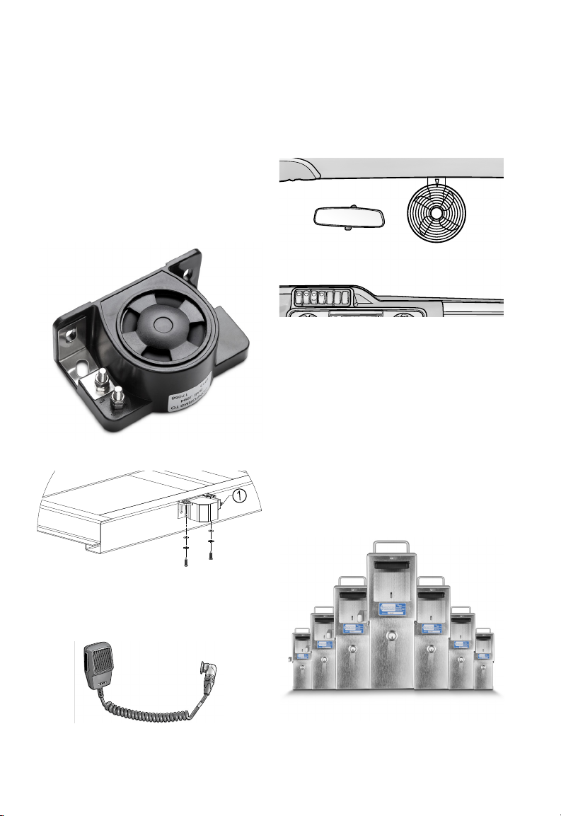
REVERSE ALARM
There are several options for reverse
alarms, based on how your bus was
equipped. Typically the alarm only
sounds when the vehicle is in reverse.
The reverse alarm may be installed
in a variety of locations based on
your bus’s equipment. It is commonly
installed under the bus on the driver’s
side, in the rear corner section.
Image: Reverse Alarm
DEFROST FAN
If equipped, the driver’s fan is mounted
in the front cab area within reach of
the driver’s seat.
Illustration: Driver’s Fan
FAREBOX VAULT
The Advantage offers several different
models of fare boxes and donation
boxes based on how your bus was
equipped. The major difference
between the styles is the type of
currency accepted. All fare boxes and
donation boxes feature high security
Medeco locks. All customer lock codes
are registered, the keys cannot be
reproduced. Replacement keys are
only available through the farebox
manufacturer.
Illustration: Location of Reverse Alarm
PA SYSTEM
If equipped, the PA Mic is dashmounted within reach of the driver.
Image: PA System Mic
Image: Fare Box
16
03 DRIVER’S AREA
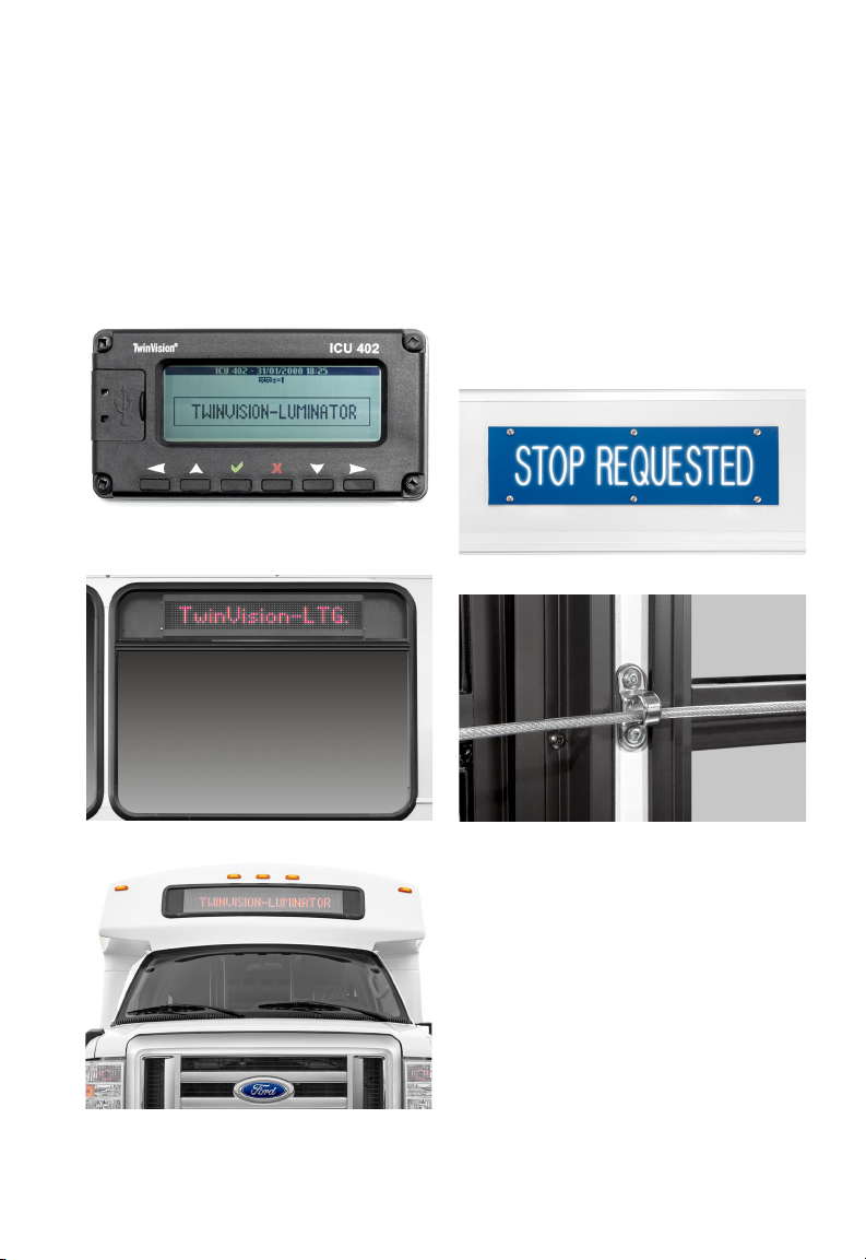
DESTINATION SIGNS
If equipped, Your bus may have front
facing and/or side facing destination
signs. Please refer to the OEM
Operator`s Manuals which came with
your bus for instructions on your signs.
u
Test system daily for proper function.
Image: Twinvision-Luminator Control Pad
STOP REQUEST
If equipped, A Stop-Request sign,
located in the drivers bulkhead, will
notify the driver and passengers to a
passenger stop-request via the PullCord which is located in the passenger
area. When the cord is pulled a chime
will sound and the sign will illuminate.
u
Test system daily for proper function.
Image: Stop-Request Sign
Image: Stop-Request Pull-Cord
Image: Destination Sign - Side Window
Image: Destination Sign - Front Of Bus
17
03 DRIVER’S AREA
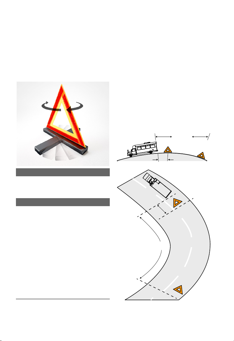
EMERGENCY REFLECTIVE
TRIANGLE WARNING KIT
To assemble Triangle:
1. Raise two (2) arms of triangle and
snap pin into slot.
2. Turn base 90° to it’s “Stop” position.
Illustration: Setting Up Emergency Triangle
i CAUTION
BEFORE LEAVING DISABLED VEHICLE
ALWAYS ACTIVATE THE VEHICLE’S
EMERGENCY FLASHERS.
i IMPORTANT
WHENEVER A COMMERCIAL MOTOR
VEHICLE IS STOPPED UPON THE
TRAVELED PORTION OF A HIGHWAY
OR THE SHOULDER OF A HIGHWAY
FOR ANY CAUSE OTHER THAN
NECESSARY TRAFFIC STOPS,
THE DRIVER OF THE STOPPED
COMMERCIAL MOTOR VEHICLE
SHALL IMMEDIATELY ACTIVATE THE
VEHICULAR HAZARD WARNING
SIGNAL FLASHERS AND CONTINUE
THE FLASHING UNTIL THE DRIVER
PLACES THE WARNING DEVICES
REQUIRED BY LAW.
HILLS, CURVES, AND
OBSTRUCTIONS
If a commercial motor vehicle is
stopped within 500 feet of a curve,
crest of a hill, or other obstruction
to view, the driver shall place the
warning signal in the direction of the
obstruction to view a distance of 100
feet to 500 feet from the stopped
commercial motor vehicle so as to
afford ample warning to other users of
the highway.
Ref. 49 CFR 392.22 - Emergency signals;
stopped commercial motor vehicles.
100’-500’
10’
10’
100’-500’
Illustration: Emergency Triangle Placement
Image Not To Scale
18
100’
(40 PACES)
10’
100’
(40 PACES)
03 DRIVER’S AREA
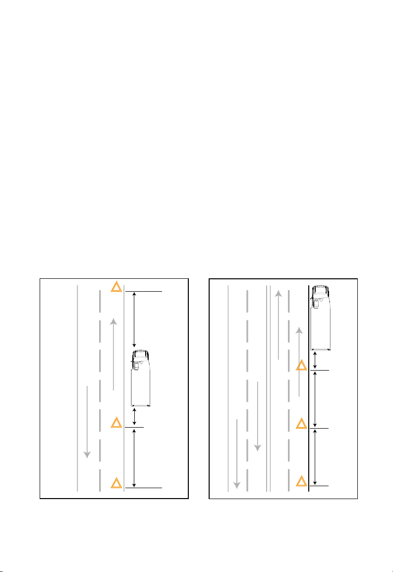
SETTING UP WARNING KIT
ON TWO (2) LANE HIGHWAY:
1. Place one (1) Reflective Triangle on
traffic side of road 4 paces (10 feet),
from the stopped commercial motor
vehicle in the direction of approaching
traffic.
2. Then place another Reflective
Triangle 100 ft. from rear of stopped
vehicle (approx. 40 paces), in the
center of the traffic lane or shoulder
occupied by the stopped vehicle.
3. Place one (1) Reflective Triangle
100ft. in front of disabled vehicle
(approx. 40 paces), from the stopped
commercial vehicle in the center of
the traffic lane or shoulder occupied
by stopped commercial vehicle in
the direction away from approaching
traffic.
100’
(40 PACES)
ON A DIVIDED HIGHWAY:
1. Place one (1) Reflective Triangle on
traffic side of road 4 paces (10 feet),
from the stopped commercial motor
vehicle in the direction of approaching
traffic.
2. Place one (1) Reflective Triangle
100 ft. from rear of stopped vehicle
(approx. 40 paces), in the center of the
traffic lane or shoulder occupied by
the stopped vehicle in the direction of
approaching traffic.
3. Then place another Reflective
Triangle 200 ft. from rear of stopped
vehicle (approx. 80 paces), in the
center of the traffic lane or shoulder
occupied by the stopped vehicle in the
direction of approaching traffic.
Ref. 49 CFR 392.22 - Emergency signals;
stopped commercial motor vehicles.
10’
100’
(40 PACES)
Illustration: Emergency Triangle Placement
Image Not To Scale
Illustration: Emergency Triangle Placement
Image Not To Scale
19
10’
100’
(40 PACES)
200’
(80 PACES)
GROUND
BOOSTERDISCHARGED
03 DRIVER’S AREA
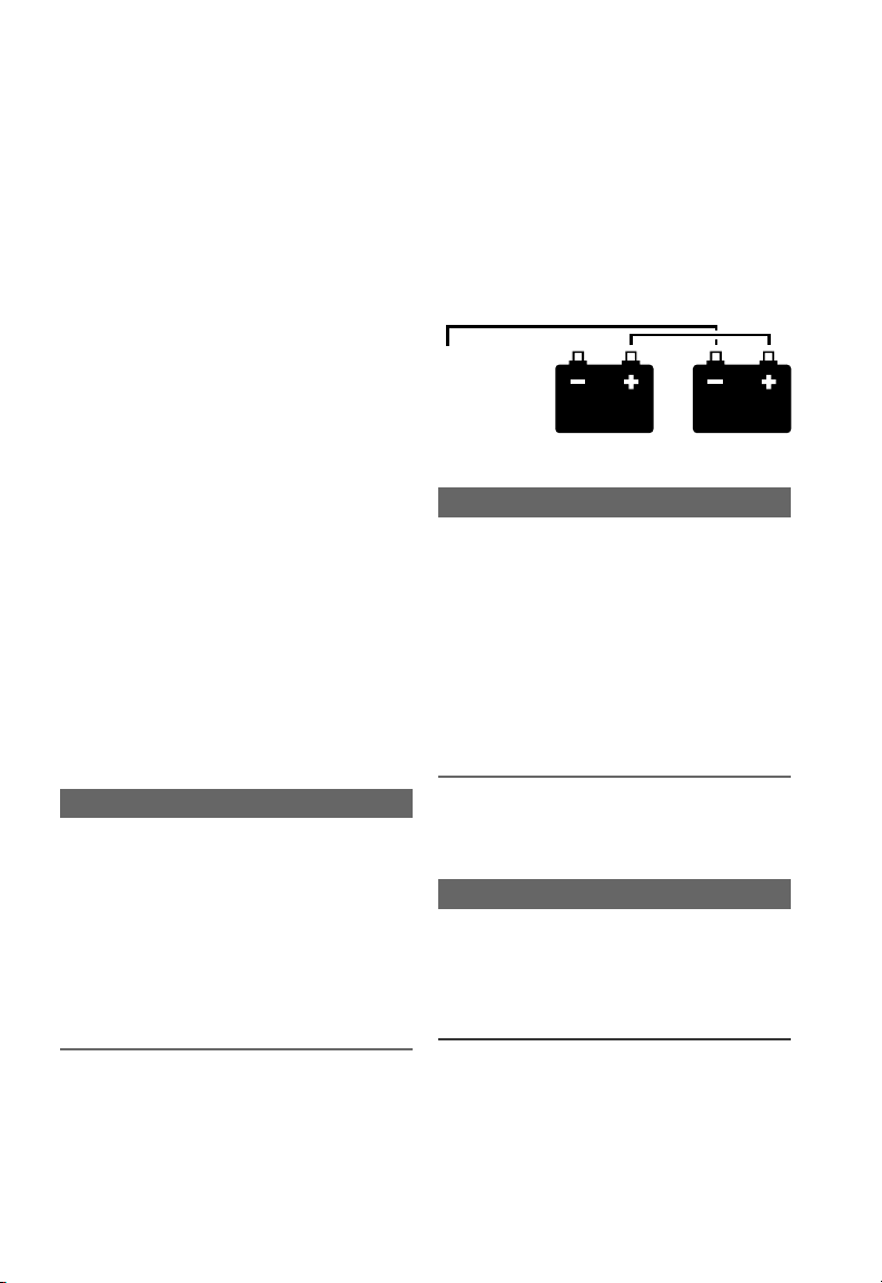
JUMPER CABLE
INSTRUCTIONS
1. Apply vehicle’s parking brake and
turn “OFF” any exterior or interior
lights that may be “ON” and any other
electrical loads.
2. Connect the (+) positive cable end of
the booster battery to the (+) positive
terminal of the discharged battery.
3. Connect the (-) negative cable
end of the booster battery to the (-)
negative terminal end (ground) at
least 12 inches (300mm) away from
the discharged batteries. The vehicle
frame usually provides a good ground.
DO NOT connect the cable to or near
the discharged batteries.
4. Start engine from the booster
batteries and let engine run a few
minutes to charge the discharged
batteries.
5. Shut “OFF” the engine, then attempt
to start engine. DO NOT operate the
starter longer than 30 seconds and
wait at least two (2) minutes between
starting attempts to allow the starter
to cool.
battery location, then disconnect other
end of (-) negative cable from booster
battery.
8. Disconnect (+) positive jumper cable
end from vehicle’s newly charged
battery first; then disconnect other
cable end from booster battery.
MIN. 12”
FROM BATT.
Illustration: Battery Jump Diagram
i CAUTION
MAKE SURE BOTH STARTING SYSTEMS
HAVE THE SAME VOLTAGE OUTPUTS
AND AVOID MAKING SPARKS.
OTHERWISE THE VEHICLE CHARGING
SYSTEMS COULD BE SEVERELY
DAMAGED. ALSO DO NOT ATTEMPT
TO CHARGE ISOLATED, DEEP-CYCLED
BATTERIES WITH JUMPER CABLES;
FOLLOW THE MANUFACTURER’S
INSTRUCTIONS WHEN CHARGING
DEEP-CYCLE BATTERIES.
i CAUTION
PERFORM THE NEXT EXACTLY AS
INSTRUCTED AND DO NOT ALLOW
THE CLAMP OF ONE CABLE TO
TOUCH THE CLAMP OF THE OTHER
CABLE, OTHERWISE A SPARK COULD
OCCUR NEAR A BATTERY, POSSIBLY
RESULTING IN SEVERE PERSONAL
INJURY FROM EXPLOSION AND ACID
BURNS.
6. When the engine starts. Let it idle a
few minutes.
7. Disconnect ground (-) negative
jumper cable from frame or other non-
CHANGING A FLAT TIRE
Refer to your OEM Operator`s Manuals
for proper jacking points.
i IMPORTANT
IF A FLAT TIRE OCCURS WHILE
DRIVING, GRADUALLY DECREASE
VEHICLE SPEED. HOLD THE STEERING
WHEEL FIRMLY, MOVE TO A SAFE
PLACE ON THE SIDE OF THE ROAD.
1. If possible, stop the vehicle on a level
surface, away from traffic.
2. Apply the parking brake and turn
“OFF” the ignition.
20

03 DRIVER’S AREA
3. Turn “ON” the emergency flashers.
4. Place warning devices, (pg 18-19).
5. Remove spare tire, jack, handle, and
lug wrench from storage, if equipped.
6. Block the wheel diagonally opposite
the wheel being changed.
The jacking point for the front and rear
wheels is directly under the axle.
7. Place the jack on a solid surface.
Insert the jack handle and pump the
handle to slightly raise the vehicle.
DO NOT RAISE THE WHEEL OFF THE
GROUND.
8. Loosen the wheel lug nuts, but do
not remove them completely.
9. Raise the vehicle until the wheel is
off the ground, then remove the lug
nuts and the wheel.
10. Install the spare wheel and lug nuts,
making sure the proper side of the
nuts face inward.
11. In a “star” pattern, tighten the nuts
evenly until snug.
12. Lower the vehicle until the wheel
touches the ground. Tighten the lug
nuts per the specifications located in
the OEM Operator`s Manuals.
13. Finish lowering the vehicle to the
ground, then remove the jack.
14. Remove the block from the
opposite tire of the repaired tire, then
stow the jack, handle and lug wrench.
15. After operating the vehicle for 100
miles (160 kilometers) refer to the OEM
Operator`s Manuals.
On vehicles equipped with single
rear wheels, re-tighten the lug nuts
to the specified torque at 100 miles
(160 kilometers), and after any wheel
disturbance (such as tire rotation,
changing a flat tire, wheel removal).
On vehicles equipped with dual rear
wheels, re-tighten the wheel lug
nuts to the specified torque at 100
miles (160 kilometers), and again at
500 miles (800 kilometers), of new
vehicle operation and after any wheel
disturbance (such as tire rotation,
changing a flat tire or wheel removal).
Always refer to your chassis manual for
proper lug nut torque settings as these numbers
may vary.
i CAUTION
WHEN A WHEEL IS INSTALLED,
ALWAYS REMOVE ANY CORROSION,
DIRT OR FOREIGN MATERIALS
PRESENT ON THE MOUNTING
SURFACES OF THE WHEEL OR THE
SURFACE OF THE WHEEL HUB,
BRAKE DRUM OR BRAKE DISC THAT
CONTACTS THE WHEEL. MAKE
SURE THAT ANY FASTENERS THAT
ATTACH THE ROTOR TO THE HUB
ARE SECURED SO THEY DO NOT
INTERFERE WITH THE MOUNTING
SURFACES OF THE WHEEL.
INSTALLING WHEELS WITHOUT
CORRECT METAL-TO-METAL CONTACT
AT THE WHEEL MOUNTING SURFACES
CAN CAUSE THE WHEEL NUTS
TO LOOSEN AND THE WHEEL TO
COME OFF WHILE THE VEHICLE IS
IN MOTION, RESULTING IN LOSS OF
CONTROL.
TOWING PROCEDURES
If you need to have your vehicle towed,
contact a professional towing service.
We recommend the use of a wheel lift
and dollies or flatbed equipment to
tow your vehicle. Do not tow with a
slingbelt. Ford Motor Company has not
approved a slingbelt towing procedure.
Vehicle damage may occur if towed
incorrectly.
21

03 DRIVER’S AREA
Your chassis manufacturer produces
a towing manual for all authorized
tow truck operators. Have your tow
truck operator refer to this manual for
proper hook-up and towing procedures
for your vehicle. Please refer to your
chassis manual for towing information.
You can flat-tow, (all wheels on the
ground, regardless of the powertrain
or transmission configuration), your
disabled vehicle, (without access to
wheel dollies or vehicle transport
trailer), under the following conditions:
• Your vehicle is facing forward so you
tow it in a forward direction.
• You shift into Neutral (N). If you
cannot shift into Neutral (N), you may
need to override the transmission.
• Maximum speed is 35 mph (56 km/h).
• Maximum distance is 50 mi (80 km).
FRONT TOW HOOKUP
1. Disconnect battery ground cable.
2. If vehicle is to be lifted from the
front and towed, remove drive axle
shaft.
i WARNING
FAILURE TO REMOVE THE DRIVE AXLE
SHAFT WHEN TOWING THE VEHICLE
WITH THE REAR WHEELS ON THE
GROUND COULD RESULT IN DAMAGE
TO THE TRANSMISSION AND OTHER
COMPONENTS.
i WARNING
IF YOUR VEHICLE HAS A STEERING
WHEEL LOCK MAKE SURE THE
IGNITION IS IN THE ACCESSORY OR
"ON" POSITION WHEN BEING TOWED.
3. Attach to towing device, (Do not tow
with a slingbelt).
4. Lift the bus and secure the safety
towing chains. If additional clearance is
needed, remove the front wheels.
i WARNING
BEFORE RELEASING THE PARKING
BRAKE, MAKE SURE THE CONNECTION
TO THE TOWING VEHICLE IS SECURED,
OR CHOCK THE DISABLED VEHICLE’S
TIRES. FAILURE TO DO SO COULD
RESULT IN HAZARDOUS CONDITIONS
BECAUSE THE VEHICLE COULD ROLL
SUDDENLY.
5. Connect clearance, tail, and signal
lights to the towing vehicle’s wire
harness. Connect any special towing
lights required by local regulations.
6. Release the parking brake.
REAR TOW HOOKUP
1. Turn the front tires to face straight
forward and secure the steering wheel
into this position.
2. Disconnect the battery ground cable.
3. Attach to towing device, (Do not tow
with a slingbelt).
4. Lift the vehicle and secure the safety
towing chains, if additional clearance is
needed, remove the bumper extension
if equipped.
5. Connect clearance, tail, and signal
lights to the towing vehicle’s wire
harness. Connect any special towing
lights required by local regulations.
Due to the many variables that exist in
towing, positioning the lifting and towing devices
is the sole responsibility of the towing-vehicle
operator, who must be familiar with industry
towing procedures and safety standards.
22

03 DRIVER’S AREA
VEHICLE SYSTEMS
SAFETY CHECKS
This bus conforms to all Federal Motor
Vehicle Safety Standards applicable
at the time of manufacture, and in
addition, incorporates other important
features. However, even with these
safety features, continued safe and
dependable operation depends greatly
on regular bus maintenance.
To retain the safety, dependability
and emission control performance
originally built into the vehicle, it
is essential that it receive regular
periodic inspection, maintenance and
service parts replacement.
Listed below are items that should be
checked prior to taking the vehicle
onto the road along with the pretrip inspection. Any deficiencies or
irregularities should immediately be
brought to the attention of service
personnel. Broken, incomplete,
damaged or worn articles should be
replaced/repaired after evaluation by
qualified personnel.
SEAT BELT
u
Check webbing, buckle, latch plate,
retractor and attaching point for
proper operation and for damage.
WINDSHIELD WIPER & WASHER
u
Check operation of wipers as well as
condition and function of wiper blades.
u
Check amount and direction of fluid
sprayed by washer during use.
MIRRORS & SUN VISOR
u
Check for proper operation and
adjust as required.
WINDSHIELD DEFROSTER
u
Check performance by moving the
fan speed switch through the various
blower settings. Note the amount of
air directed against the windshield
and the direction of air flow across the
windshield.
LIGHTS & BUZZERS
u
Check all instrument panel warning
lamps, and all interior and exterior
lights for proper illumination. Any
components found to be defective
or inoperative should be repaired or
replaced.
DOORS, WINDOWS & EMERGENCY
ESCAPES
u
Check for positive opening, closing
and latching operations. Check that
window emergency release levers
work properly and that windows open,
close and latch properly. Check that
all compartment and passenger doors
are securely closed by attempting to
re-open after each use. Also check for
broken, missing or loose parts that can
prevent positive latching.
WHEEL ALIGNMENT & TIRE
BALANCE
u
In addition to uneven or abnormal
tire wear, the need for wheel alignment
service may be indicated by a pull
to the left or right while driving on a
straight and level road. The need for
wheel balancing is usually indicated
by vibration of the steering wheel or
seat while driving at normal highway
speeds. Contact service personnel for
repair if either condition is present.
FLUID LEAKS
u
Check for fuel, water, oil or other
fluid leaks by observing the surface
beneath the bus after it has been
parked for a period of time (water
dripping from the air conditioning
system is normal). If diesel fuel or
gas fumes are noticed at any time,
the cause must be determined and
immediately corrected to reduce the
risk of fire.
23

03 DRIVER’S AREA
EXHAUST SYSTEM
u
Be alert to any changes in the sound
of the exhaust system or the smell of
exhaust fumes. This could indicate an
exhaust leak requiring repair at the
first available opportunity.
SEAT ADJUSTERS
u
Check that the seat adjuster
engages securely by pushing forward
and backward on the seat whenever
adjustments have been made.
STEERING
u
Be alert to any changes in steering
action. The need for inspection or
service is indicated if there is increased
steering effort, excessive free play
in the steering wheel or any unusual
sounds when turning or parking.
PARKING BRAKE
u
Check the parking brake by parking
the bus on a slope and setting the
brake. The vehicle should remain
stopped while the brake is applied.
BRAKES
u
Changes in braking action such as
pulling to one side, increased pedal
travel or unusual sounds when braking
or between brake actuations should be
reported and corrected immediately.
GAUGES, STEERING COLUMN,
TACH, TRANSMISSION, PARKING
BRAKE AND INSTRUMENTATION
u
Please refer to your OEM Operator’s
Manuals for any information on your
vehicles gauges, steering column,
tach, transmission, parking brake and
instrumentation guide.
Your OEM Operator’s Manuals are
included in your vehicle package.
i CAUTION
AS WITH ANY MACHINE, CARE
SHOULD BE TAKEN WHEN
PERFORMING ANY INSPECTION,
MAINTENANCE, OR REPAIR SO AS
TO MINIMIZE THE RISK OF INJURY.
IMPROPER OR INCOMPLETE
SERVICING CAN RESULT IN PERSONAL
INJURY OR VEHICLE DAMAGE.
SHOULD THERE BE ANY QUESTION
ABOUT SERVICING THE VEHICLE,
REFER REPAIRS TO QUALIFIED
PERSONNEL.
24

03 DRIVER’S AREA
REAR CARGO STORAGE
If equipped, rear cargo compartments,
offer spacious storage for all shapes
and sizes of luggage and leisure-type
gear. Optional racks and shelving can
be tailored to your requirements.
Compartments feature door-activated
interior lighting and lockable cargo
doors for easy access and security.
Optional warning lights and buzzers
are available to warn the driver when
the doors are unlatched.
Drivers and baggage handlers should
take care to arrange their cargo so
as to minimize movement in transit.
Suitcases free to fall or shift during
sharp turns or quick stops can cause
damage to contents and create a
negative impression of your bus
service. Cargo storage door jamb seals
should be checked regularly for a tight
fit to keep dust and moisture out of the
luggage area.
OPEN-SHELF STORAGE
If equipped, shelving and racks
located behind the driver’s area, let
passengers stow their own suitcases
and other large items as they enter
the bus — without assistance from the
driver. This type of storage is similar to
compartments found on commercial
aircraft and offers the same time
saving, self-service convenience.
It’s a good practice to check fasteners,
screws, etc. on the interior luggage fixtures on a
regular basis to make sure they are tight, and the
fixture is in sound operating condition.
OVERHEAD STORAGE
If equipped, overhead compartment
storage, provides convenient storage
for smaller personal items. They are
often used on transit, tour, and airport
buses, where passengers are likely
to be carrying packages and extra
personal items.
i IMPORTANT
DRIVERS SHOULD MAKE SURE THAT
THE ITEMS STOWED WILL NOT FALL
INTO THE AISLE DURING TRANSIT OR
OTHERWISE OBSTRUCT EGRESS AND
ENTRY.
i IMPORTANT
PASSENGERS CAN EASILY BE
INJURED BY OBJECTS FALLING
FROM OVERHEAD STORAGE.
DRIVERS SHOULD MAKE EVERY
EFFORT TO MINIMIZE THIS RISK.
ONE PRECAUTION IS TO WARN
PASSENGERS THAT HEAVY
ITEMS SHOULD NOT BE PLACED
IN THE OVERHEAD STORAGE
COMPARTMENTS.
25

03 DRIVER’S AREA
DRIVING ON SNOW OR ICE
When operating the vehicle on snow
or ice, reduce speed gradually. Select
a gear range that will not exceed
the speed you expect to maintain.
Accelerate or decelerate very gradually
to avoid losing traction. It is very
important to reach the gear in the
lower range selected by letting the
transmission shift down automatically
while gradually slowing. It is important
to slow gradually when a lower range is
selected. It is also important that you
reach the lower range selected before
attempting to accelerate. This avoids
unexpected down-shifting during
acceleration.
DO NOT use the retarder during
inclement weather or when the road
surfaces are slippery due to ice or rain.
i CAUTION
DRIVING THROUGH DEEP WATER,
OR SNOW WILL ADVERSELY AFFECT
BRAKING PERFORMANCE.
ROCKING THE VEHICLE
This section does not apply to vehicles
equipped with ATC (Automatic Traction
Control).
If the bus is stuck in mud, sand or
snow, it may be possible to “rock”
out. Shift to “Drive” and apply steady,
light throttle – and NEVER full throttle.
When the bus has rocked forward
as far as it will go, apply and hold
the service brakes. Allow the engine
to return to idle, and then select
“Reverse”. Release the brakes and
apply a steady, light throttle and allow
the bus to rock in “Reverse” as far as
it will go. Again, apply and hold the
service brakes and allow the engine to
idle. Never make "Neutral" to "Drive"
or directional shift changes when the
engine RPM is above idle.
To avoid injury or property damage
caused by sudden bus movement, do
not shift from “Neutral” to “Drive” or
“Reverse” when the throttle is open.
Shifting with the throttle above idle
causes the transmission to delay
engaging unless the throttle is closed
within the next three (3) seconds.
Leaving the throttle open longer than
three seconds causes the transmission
to remain in “Neutral”. When the
throttle is subsequently closed or
brought back down, the transmission
can engage without warning, causing
sudden movement of the vehicle. Avoid
this condition by making shifts from
“Neutral” to “Drive” or “Reverse” only
at idle.
Do not make “Neutral-to-Drive” or
directional shift changes with engine
RPM above idle. If the wheels are
stuck and not turning, do not apply
full power for more than 30 seconds.
Full power for more than 30 seconds
under these conditions will cause
the transmission to overheat. If the
transmission overheats, shift to
“Neutral” and operate the engine at
1200-1500 RPM until it has cooled
down (approximately 2-3 minutes).
Turn the retarder (if equipped) “OFF”
when operating the bus in inclement
weather, or when road surfaces are
slippery.
26
04 DOORS & WINDOWS
DOORS
The ElDorado Advantage installs bus
doors, except for the driver’s door,
according to the options specific to
each bus. Passenger entry doors,
paratransit doors, cargo doors, and
emergency exit doors are available for
various applications throughout the
bus. Regardless of the door type, regular inspections and routine maintenance will help keep doors functioning
properly.
KEY LOCKS
u
Lubricate key locks with a graphite-
type lubricant that is recommended for
door locks. Do not use lightweight or
detergent-type lubricants as they may
wash the original graphite lubricants
out of lock tumblers, harming the
functioning of the key locks.
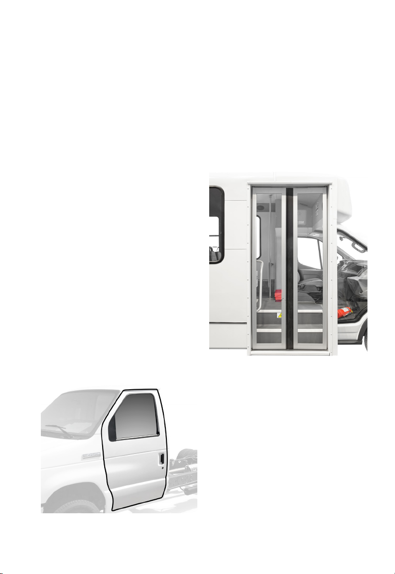
CHASSIS CAB DOOR
The chassis cab door is a typical
automotive style door with a standard
release handle, window crank, and door
locking mechanism.
The ElDorado Advantage does not
modify the chassis cab door in any way.
For additional information regarding
door operation and maintenance
consult the chassis owner’s manual.
Image: OEM Chassis Door
PASSENGER ENTRY DOOR
The passenger entry door is located
on the curb side of the bus and is
operated electrically. The steel door
frame and step well are fixture welded
to form a single unit which offers
strength and durability. Door panels
open outward and are mounted in the
door frame with pivot pins at the top
and bottom.
Image: Standard Passenger Door
HINGES
u
Lubricate hinges and closing mech-
anisms monthly with one or two drops
of light machine oil. This helps prolong
the life of hinge pins and closing mechanisms, prevents corrosion, binding,
and squeaks. SAE 5 weight non-detergent motor oil and/or WD-40TM spray
work well for these lube applications.
White lithium grease is also recommended to lubricate the closing mechanism linkage.
Avoid over-lubrication as excess oil
or grease tend to collect dirt and soil
clothing.
27
04 DOORS & WINDOWS
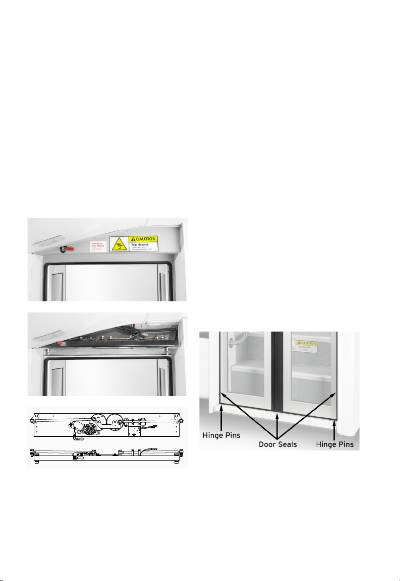
DOOR ACTUATOR COVER
The door actuator cover is located
above the passenger entry door. This
cover protects the door linkage, actuator, and door motor, (on electric doors
only). To access the door mechanism,
use a Phillips screw driver to remove
the securement fasteners. Then the
cover can be removed to access the
door mechanism. Simply reverse the
removal steps to re-install the cover.
Keep the door actuator cover installed at all
times, (except when repairs are being made), for
safety and to protect the door mechanism.
Image: Door Actuator Cover Installed
DOOR SEALS
u
Inspect door seals every week for
material quality and tight door closure.
u
Repair or replace damaged seals, as
necessary.
u
Spray door seal surfaces with a light
coating of silicone every 12,000 miles
or 3 months to keep the seals supple.
If door seals do not close tightly and they
do not show excessive wear, adjust the closing
mechanism according to the diagrams included
with the bus door, (information following in this
section).
Avoid over-lubrication as excess oil or grease
tend to collect dirt and may soil clothing.
DOOR ALIGNMENT
u
Check door alignment every week.
Over time, worn door pins and loose
fasteners may allow door hinges to
shift.
u
Tighten loose nuts, replace worn
parts, and/or realign doors as
necessary.
Image: Door Actuator Cover Removed
Illustration: Door Actuator Unit - Ortho Views
Image: Door Hinge And Seals
28
 Loading...