

Eldom Invest HPS120, HPS120S, HPS150, HPS150S Installation, Use And Maintenance Instructions
HEAT PUMP SYSTEMS WITH ADDITIONAL
WATER HEATERS (HEAT PUMP SYSTEMS)
OF 120 and 150 l.
DESIGNED FOR WALL
MOUNTING
SPECIFICATIONS
INSTALLATION, USE AND MAINT ENANC E INST R UCTIONS
IMPORTANT RUL ES
WARNING! Before installing and operating the water heater read carefully the instructions!
1
SPECIFICATIONS, INSTRUCTIONS FOR INSTALLATION AND USE HEAT
PUMP SYSTEMS WITH ADDITIONAL WATER HEATER
(HEAT PUMP SYSTEMS)
OF 120 AND 150 l. (EN 60335-2-40)
DESIGNED FOR WA LL MOUNTING (hanging)
Before beginning installation and operation of Your unit it is compulsory to read the complete
text of this instruction. It must be observed as well by You, in order to help You operate and use
the system, as well by the qualified workers who shall install and eventually maintain and repair
the unit in case of malfunctioning. Compliance with rules in present instruction booklet shall be a
prerequisite for system safe use and is part of warranty requirements.
CAUTION!
qualified persons and in accordance with the provisions of national legislation.
IT IS COMPULSORY
CAUTION!
The unit must be properly connected to both power conductors and to protective circuit! Do not
connect the unit to power supply before its water tank is completely water filled!
CAUTION!
unit must be properly connected and secured against refrigerant leak into the atmosphere.
WARNING!
water in the water heater is heated to temperatures closer the thermostat higher limit.
WARNING!
physical, sensory or mental capabilities, or lack of experience and knowledge, unless they have
been given supervision or instructions concerning use of the appliance by a person responsible
for their safety! Children should be supervised to ensure that they do not play with the
appliance!
Unit installation and connection to the water supply network must be completed by
to install only manufacturer supplied safety and other fittings!
Connection to the power supply network must be completed by qualified workers.
The connection of unit two bodies must be carried out only by qualified workers. The
When using the appliance there is a risk of hot water scalding, especially when the
This appliance is not intended for use by persons (including children) with reduced
ENVIRONMENTAL PROTECTION
This appliance is marked according the REGULATION concerning requirements for marketing
electrical and electronic devices and the treatment and transport of waste from electric and
electronic equipment. By ensuring this product is disposed of correctly, you will help prevent
potential negative consequences for the environment and human health, which could otherwise
be caused by inappropriate waste handling of this product.
The symbol
appliance may not be treated as household waste. Instead it should be handed over to the
applicable collection point for the recycling of electrical and electronic equipment. Disposal must
be carried out in accordance with local environmental regulations for waste disposal. For more
detailed information about treatment, recovery and recycling of this product, please contact your
local city office, your household waste disposal service or the shop where you purchased the
product.
on the product or on the accompanying documents indicates that this
2
SPECIFICATIONS
Water heaters operated with heat pumps are designed for household use and serve to
provide hot water from the water supply network for several consumer points – kitchen,
bathroom, etc.
The appliance transfers heat energy from the environment in the water tank, thus heating
water contained. Energy is extracted directly from the air. A small quantity of electricity is
required to operate the compressor. The amount of heat produced by the heat pump operation
is more than three times the input electricity. The heat pump operated water heaters of
Eldominvest Ltd. Consist of two parts: outdoor unit, or body, with compressor and heat
exchanger, and indoor unit, or body, consisting of water heater with heat exchanger –
condenser. Both units are connected with pipes through which flows refrigerant.
Within the external unit package you shall find the stand for appliance wall mounting and a
corrugated plastic pipe for external unit drainage.
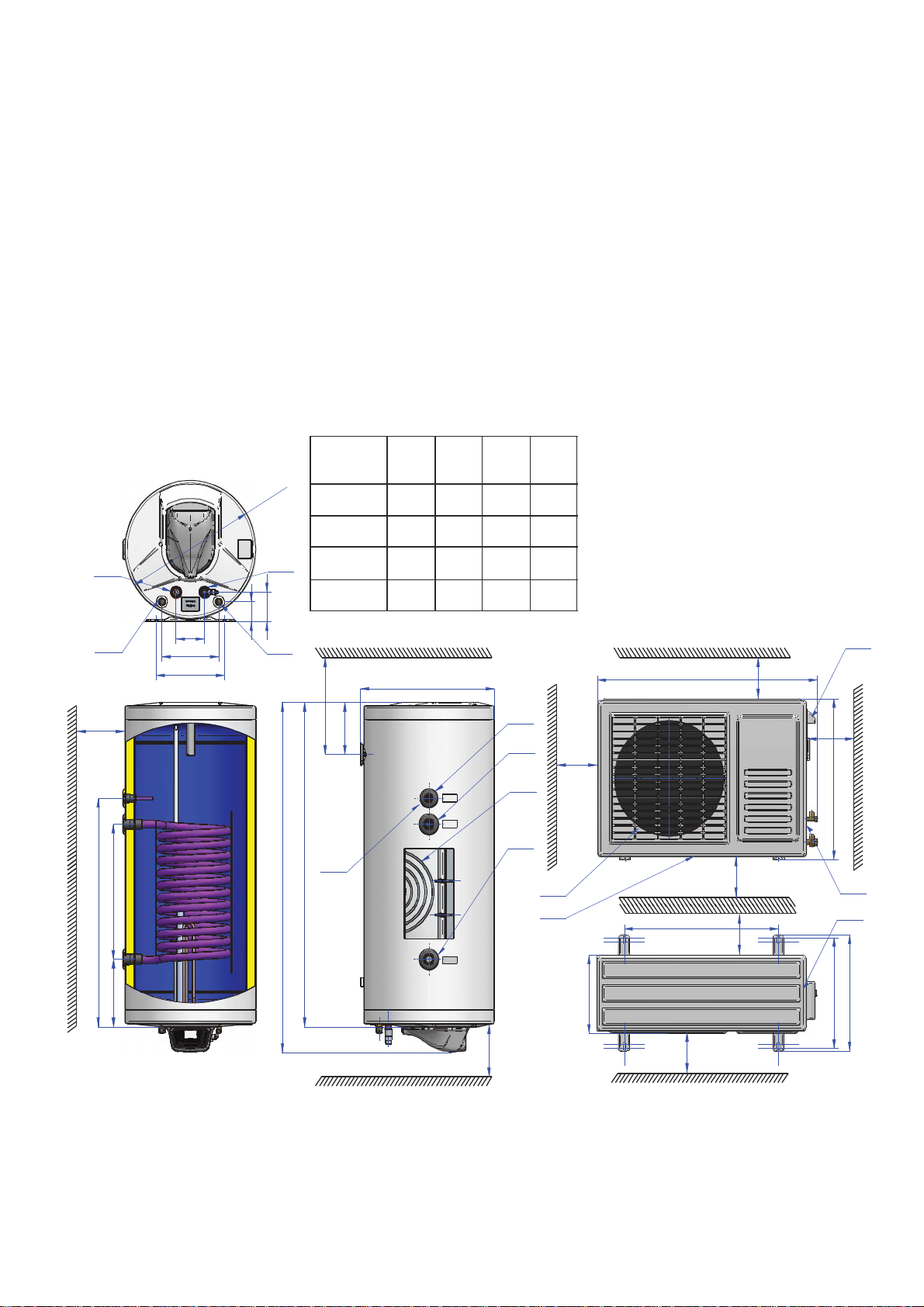
On Fig. 1 you may see a schema with dimensions and the specification data in Table 1.
Fig.1
6
7
min 250
100
200
240
66
Model L1
0
6
4
O
98
HPS120 1165 1090 1070 -
HPS120S 1165 1090 1070 450
HPS150 1415 1330 1310 -
5
HPS150S 1415 1330 1310 537
8
min 250
173
[mm]L2[mm]L3[mm]
471
L4
[mm]
1
2
3
1. Thermostat coupling
2. Solar heat exchanger inlet
3. Condenser
4. Solar heat exchanger outlet
5. Cold water inlet
6. Hot water outlet
7. Refrigerant – gaseous phase
8. Refrigerant – fluid phase.
min 200
8532
min 500
min 800
2
4
B
L3
L4
225
Table 1.
L1
4
M
L2
380
C
D
400
A
E
268
min 350
min 800
min 100
560
min 300
3
Model
Water heater tank nominal
volume
Heat pump rated nominal
heating power
Electric heater rated
nominal heating power
HPS120 HPS120S HPS150 HPS150S
120 l 150 l
3000 W
2000 W
Nominal tension 220-240 V~
Heat pump nominal electric
capacity
Heat pump maximum
electric power
780 W
1020 W
Total maximum power 3020 W
Starting current 21,15 А
Refrigerant R417A 0,8 kg
Operating temperature
range
System maximum pressure
with refrigerant
System minimum pressure
with refrigerant
Maximum tolerated system
pressure with refrigerant
Water tank nominal
pressure
Surface of the water heater
solar heat exchanger [m
2
]
Outdoor unit waterproof
class
Indoor unit water protection
class
-0,65-0,89
-10° ÷ 40°
2,7 MPa
0,7 MPa
2,8 MPa
0,8 MPa
IPX4
IPX1
Outdoor unit level of noise 49 dB(A)
The water tank unit is properly protected from corrosion with high quality enamel lining or high
quality chrome-nickel steel. Within the enameled water tanks are inserted anodes of special
alloy, which during its wear provide additional protection of the enamel lining.
The water used for heating must comply with legislation in force for household water quality
and in particular its chlorides content must be below 250 mg/l, while its conductivity must be
over 100 μS/cm and below 2000 μS/cm for water heaters with enameled tank and under 600
μS/cm for water heaters with water tank of high quality chrome-nickel steel.
The unit’s outer body is made of steel with epoxy polymer coating, while thermal insulation is
completed with Freon less polyurethane foam.
Water heater modifications are marked with numbers and letters as follow:
„HPS” – means heat pump operated water heater.
The numbers 120 and 150 mean that the water heater tank has a volume of 120 or 150 liters.
„Н“ means that the appliance water tank is made of chrome-nickel alloy steel.
“S” means that the water heater is equipped with solar heat exchanger.
The maximum pressure tolerated in a system with refrigerant for the heat pump water heaters
is 2,8 МРа. These systems are tested and designed to operate at pressures lower than 2,8МРа.
4
For this aim within their structure is mounted a fuse to prevent that the system reaches a higher
than acceptable pressure.
The heat pump heaters are intended to heat water not only with their heat pump system, but
as well with 2 000 W electric heater. It is possible to heat water only with the appliance electric
heating element.
WATER HEATERS WITH SOLAR HEAT EXCHANGERS
These models water heaters provide the opportunity to save electricity thanks to the
integrated heat exchanger. When operating the latter allows heating the water volume from
alternative heat source such as a solar collector. It is necessary to use within the system a heat
transfer fluid not exceeding 85° С.
WARNING!
IT IS ABSOLUTELY FORBIDDEN to allow heat transfer fluid circulation through
the heat exchanger when the water tank is empty. IT IS ABSOLUTELY FORBIDDEN to close
simultaneously the heat exchanger inlet and outlet.
For heat transfer fluid always use a solution of propylene glycol diluted with water in a ratio
consistent with environmental climatic conditions. Installation and connection of the water
heater heat exchanger to it must be carried out only by qualified and licensed companies with
same business in accordance with specific project.
INSTALLING THE WATER HEATER (INDOOR UNIT) TO THE WALL
The water heater (indoor unit) may be installed only in premises with regular fire safety and
where temperature may never drop below 0°С. It is necessary as well that the floor in the
premise be equipped with trap for wastewater, as it is possible during normal operation from the
relief valve outlet from time to time to drip water. The wastewater trap shall ease maintenance,
prevention and service operations for the water heater requiring drain of tank water.
The place for installation of the water heater must comply with its dimensions, way of
mounting, and location of fixing elements and pipes and its waterproof class of protection. The
latter is noted on the appliance plate serial number. It is absolutely necessary that the appliance
is protected from dripping or spraying with water.
Water heater must be rigidly mounted to the premise wall. For the purpose apply firmly
fastened in the wall steel bolts (pins) of 10-12 mm diameter. The fasteners must be secured
against pulling out of the wall, i.e. these must be anchor bolts or bolts passing through the wall
section (depending of wall material). It is not allowed to mount the water heater on decorative
walls (of single bricks or lightweight materials).
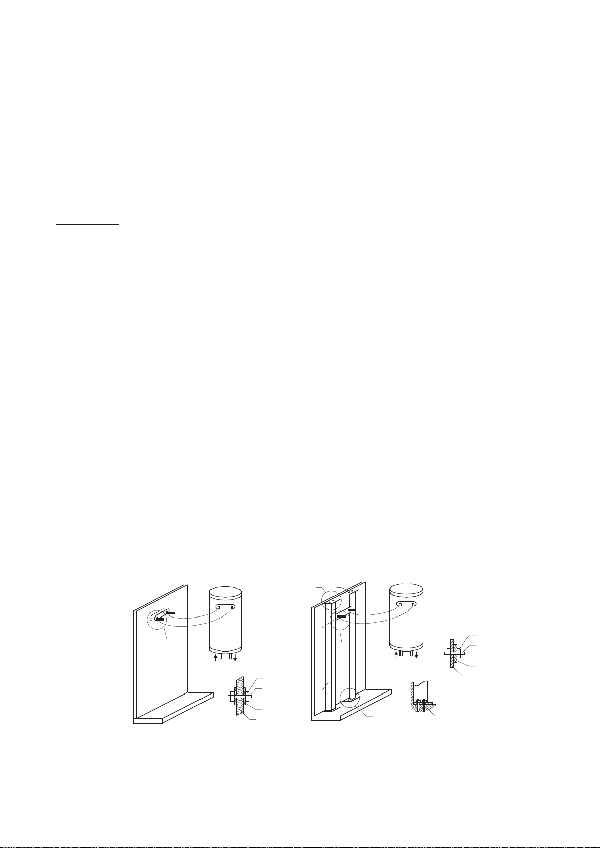
Mounting on support wall. Support walls are those
made of reinforced concrete or masonry with solid
bricks with thickness at least 25 cm.
A
Mounting on curtain wall. Curtain wa lls are those
made of masonr y wit h non-solid bricks or oth er light
materials.
B 6
1
A
A
4
3
Fig. 2
1. Wall; 2. Plate; 3. Pin; 4. Nut
2
A
4
3
2
1
5
B
1. Plate (4x60x3 60); 2. Unit plate; 3. Bol t (pin) M10; 4. Nut;
5. Column (set square 50x50x5); 6. Plate (4x100x100);
7. Treenail for concrete.
NOTES: 1. Posit ions 1, 5 and 6 are welded.
2. The premise floor and c eiling are made of rei nforced concrete.
B
1
7
5
WARNING! Failure to comply with requirements for fixing the water heater to the wall may
cause damage to the appliance or to other appliances in the premise where it is located, to
corrosion or even more severe damages and harms. In such cases eventual damages and
harms shall not be covered by the manufacturer or seller warranty liabilities and shall be at the
expense of those violating these instructions.
Only qualified workers shall be allowed to mount the water heater on the wall.
MOUNTING THE OUTDOOR UNIT
RECOMMENDATIONS: Use only the fittings supplied in the delivery set and placed in the
package for the external unit wall mounting stand and the supplied corrugated drainage pipe.
CAUTION!
requirements:
а) Find the most suitable position with enough space on the wall in order to make easier the
installation and maintenance of the outdoor unit (Fig. 1);
b) The outdoor unit is installed on support or curtain wall with built support structure. The place
must be safe in any respect and noise and cold air must not cause any problems. For mounting
the unit use fastening brackets. The place must not allow passage near the outdoor unit and
must ease discharge of condensation water;
c) The outdoor unit must be installed completely horizontal. (Fig. 1);
d) Provide space for connection of pipes and power cables, as well as an opening in the wall
where these shall pass through;
e) Mount the unit securely on the wall with suitable screws or anchors (pay attention for hidden
cables and pipes). Secure the location against vibrations.
f) Condensation or water appearing during outdoor unit operation must be removed and offset
through drainage. A nipple or flexible sleeve may be installed in order to secure free flow of
water (Fig. 3).
Before starting installation be sure that the place selected fulfills the following
Fig.3
6
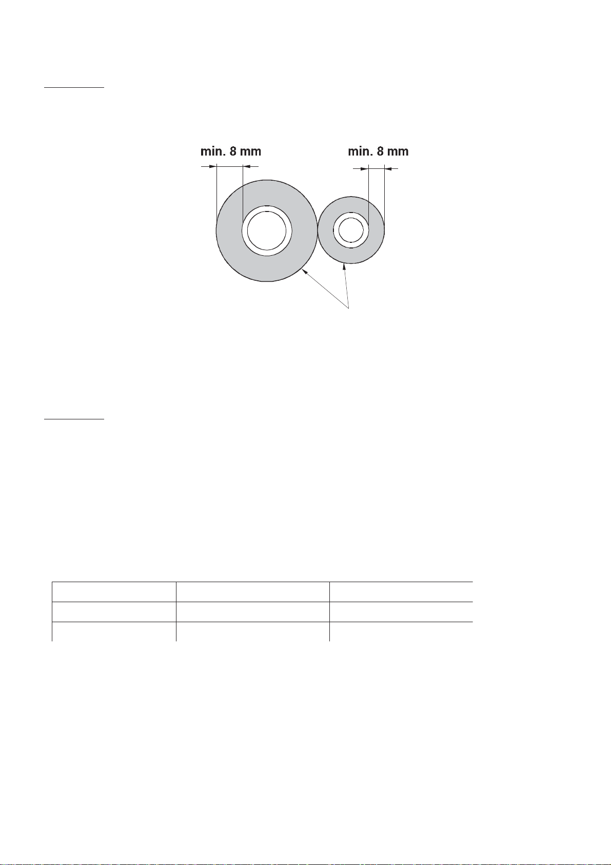
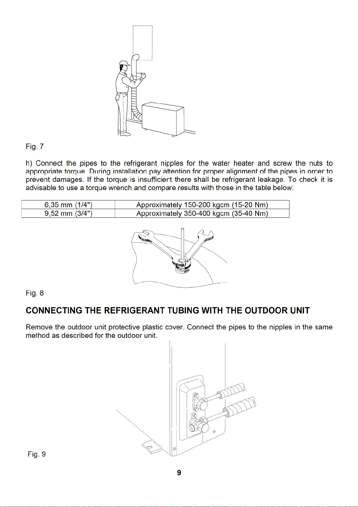
REFRIGERANT PIPES PREPARATION
Insulation
CAUTION! Before starting installation check for the following:
а) Apply copper tubing used for installation of air conditioning systems (1/4'' and 3/8”) with
appropriate insulation (at least 8 mm), Fig. 4, suitable for use with refrigerant R417a;
Fig. 4
b) Do never apply pipes thinner than 0.8 mm;
c) Secure the simplest and shortest passage (max. distance 8 m. length and 3 m displacement),
d) Protect both pipes and cables to prevent damages.
CAUTION!
prevent burns, cuts or loss of product.
The pipes should not be wet and dirty. Avoid any sharp bends of pipes or harm to its cylindrical
shape. Any bending must be carried out with suitable tool.
The pipes and fittings for the refrigerant must be thermally insulated in order to
CONNECTING THE REFRIGERANT TUBING WITH THE INDOOR UNIT
(WATER HEATER)
а) Unfold required pipes length from the rolls;
Marking External diameter [mm] Thickness [mm]
1/4“ 6,35 0,8
3/8“ 9,52 0,8
b) Remove the refrigerant nipples protective nuts of the indoor unit (make sure there is no dirt or
moisture);
c) Cut the pipes desired length with suitable tool avoiding formation of burrs and distortions. The
cut must be perpendicular to the pipe axis (Fig. 4);
7
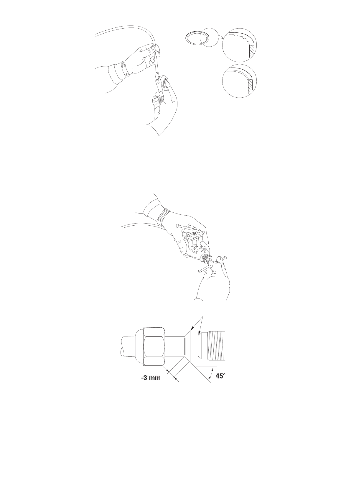
Fig.5
Grease
d) Remove the burrs or other contaminants (if any) in order to prevent passing in the system;
e) Place insulation on the pipes;
f) Place the pipes brass nuts in the right direction and make cones on pipe’s both ends in
suitable shape and size with appropriate tool. (Fig. 6):
Fig. 6
g) Connect the two pipes with insulation with the power and communication cable in a bundle
and wrap it tightly with PVC tape with UV protection.
8
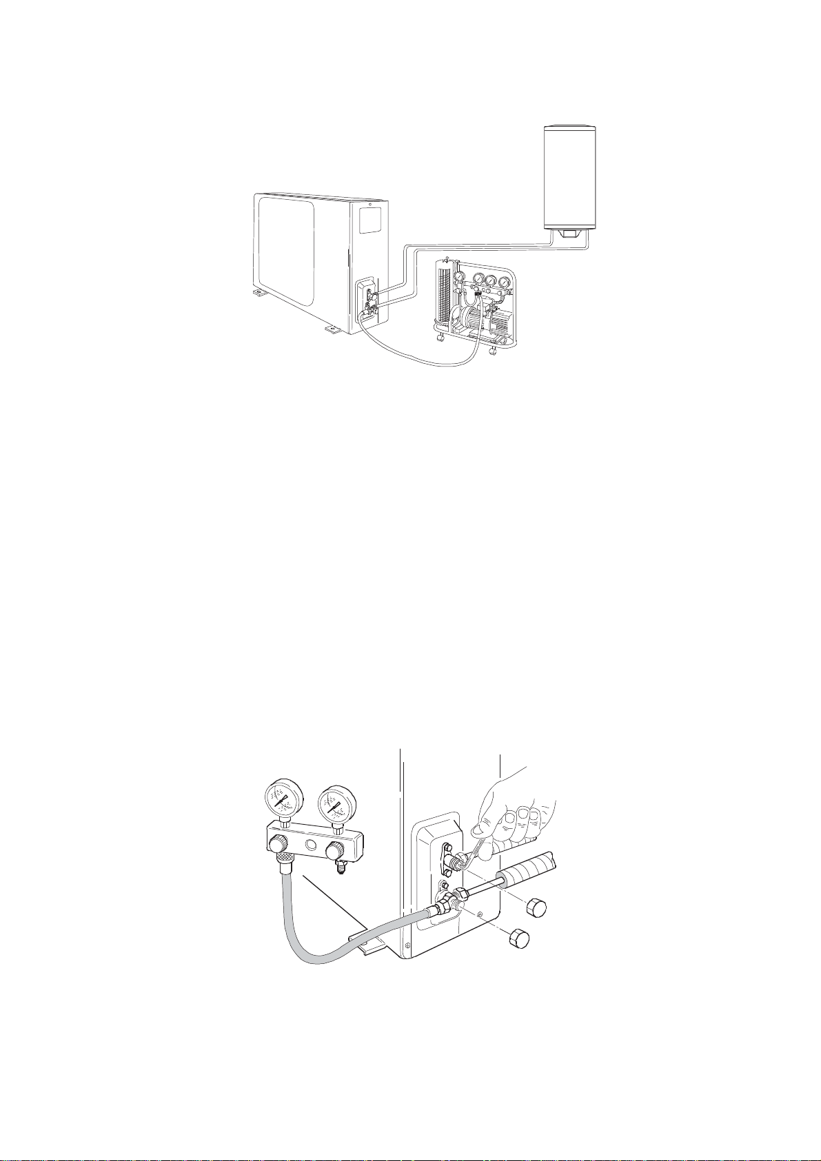
SYSTEM VACUUMING AND CHECK FOR LEAKS
Fig. 10
It is first necessary to purge the air from the system with a vacuum pump. Both connections
and gauges must be adapted to R417A (or R22). Make sure the vacuum pump is in good
working condition.
а) Remove the plugs of the outdoor unit two and three-way valves, as well as of the service
valve. Check if both valves of the outdoor unit are closed;
b) Connect the vacuum pump to the service valve;
c) After opening the valve plug the pump and let it run. It shall make vacuum for about 20-25
minutes.
d) Check whether the pressure gauge indicates pressure equal to 1 bar (or -76 cm Hg);
e) Close the pump valve. Make sure that the pressure gauge arrow does not move for at least 5
minutes. If the arrow is moving it means that within the system penetrates air and it shall be
necessary to check all connections. After finding and fixing the leak repeat the procedure from
start.
f) Turn off the pump and remove the hose connected to the service valve.
g) Open completely the two and three-way valves using Allen key.
h) Screw and tighten the valve plugs.
i) Check for refrigerant leaks with appropriate detector.
Fig. 11
10
ADDING REFRIGERANT
CAUTION! It is compulsory that this procedure be performed only by qualified workers.
The outdoor unit is pre-charged with refrigerant suitable for system operation with tubing length
up to 8 m. Longer piping length may affect adversely system performance. Overflowing with
refrigerant shall have same negative impact on system operation.
If it is necessary to add refrigerant R417a to the system, it should be known that for each
additional meter of tubing must be added 20 g refrigerant and the following shall be necessary:
а) electronic balance with accuracy to 10 g;
b) bottle with refrigerant R417a.
It shall as well be necessary to use a hose with appropriate charging connections.
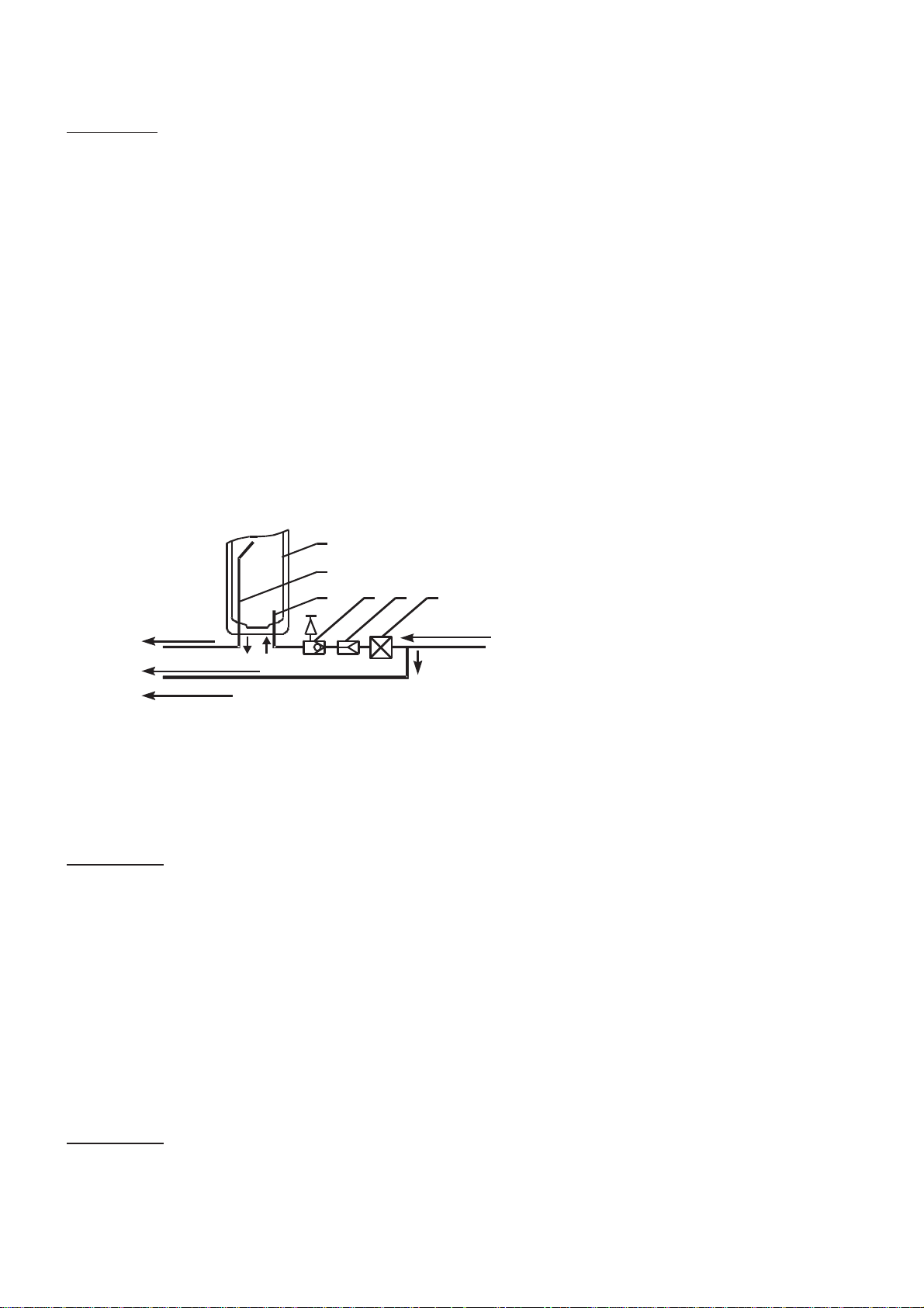
CONNECTING THE WATER HEATER (INDOOR UNIT) TO WATER SUPPLY
NETWORK
When connecting the water heater to the hot and cold water in the building plumbing you must
comply with arrows and pointing rings on water heater pipes. The cold water pipe is indicated
with arrow and blue color (inlet pipe), while with arrow and red colour – the hot water pipe
(outlet pipe). Pipes ends are threaded 1/2”. You may refer to water tank connection scheme on
Fig. 12.
1
1. Water tank;
2. Inlet pipe;
3. Outlet pipe;
4. Closing valve (option);
5. Combined valve;
6. Reduction valve (where necessary, i.e. with
water supply network pressure over 0.6
MPa)
Hot water
To mixing tab
Cold water
3
2564
Cold water
The water heater is fit with combined check-safety valve mounted on the cold water pipe in
factory.
The minimum water supply pressure for system normal functioning is 0,2 МРа.
WARNING!
It is not allowed to install check or shut-off valves between the combined valve and
the water heater! It is absolutely forbidden to clog the combined valve side hole and/or block its
lever!
If necessary you may shape a drainage system for the water dripping from the combined valve
side hole. The drainage water must have constant downward gradient, located in frost free
environment and its ends permanently connected to the atmosphere.
Following its connection to the water supply network the tank must be filled with water. The
steps of this procedure are as follow: open completely the hot water tap of the farthest mixing
tap; then open the shut-off valve, pos. 4 on Fig. 12; and wait until dense water jet flows out;
close the hot water mixing tap and lift the combined valve lever, then wait about 30-60 seconds
until complete and full water jet flows; close the valve lever.
WARNING!
If from the valve there is no water flow or the jet is insignificant (at normal pressure
in the supply network), this is a malfunction indicating that impurities from the plumbing
connections or pipes have blocked the safety valve of the combined valve.
11
 Loading...