

eldoLED LINEARdrive User Manual
LINEARdrive Display
User manual


LINEARdrive Display
User manual
4
Disclaimer
All information and content available on or accessible through the eldoLED website, all information contained in any eldoLED documentation, whether provided electronically or in hardcopy, such as product
manuals, and all information and content in e-mails or other ways of communication used by eldoLED,
(collectively hereafter referred to as: ‘the Information’) has been prepared solely fro the purpose of providing information about eldoLED products and teh eldoLED companies (“eldoLED”as used herein, refers to eldoLED B.V. and any of its affiliated companies.) While the content hereof has been prepared by
eldoLED with the utmost care, some information may nevertheless be incomplete, incorrect or may become outdated in time. TO THE FULLEST EXTENT PERMISSIBLE BY LAW, ELDOLED MAKES NO
REPRESENTATIONS OR WARRANTIES OF ANY KIND, WHETHER EXPRESS OR IMPLIED, FOR
THE CURRENCY, ACCURACY, OR COMPLETENESS OF ANY INFORMATION, AS DEFINED
ABOVE. FURTHERMORE, ELDOLED MAKES NO REPRESENTATIONS OR WARRANTIES IN CONNECTION TO ITS PRODUCTS, INCLUDING WARRANTIES ABOUT ITS PRODUCTS’ MERCHANTABILITY OR FITNESS FOR A PARTICULAR PURPPOSE, UNLESS EXPLICITLY MADE AND
PROVIDED BY ELDOLED IN WRITING TO THE PURCHASER OF ITS PRODUCTS. The provided Information must not be relied upon in connection with any investment decision.
eldoLED B.V. cannor be held liable for any direct or indirect loss or damage resulting from the use of the
Information and/or resulting from the use of its products or material(s), except in the event of actions
verging on eldoLED’s gross intent or intentional recklessness. ELDOLED’S MAXIMUM AGGREGATE
LIABILITY FOR ANY CAUSES WHATSOEVER, AND REGARDLESS OF THE FORM OF ACTION,
WILL AT TIMES BE LIMITED TO 100,- EURO OR THE PURCHASE AMOUNTS PAID TO ELDOLED,
IF ANY, IN CONNECTION TO THE PRODUCTS ON WHICH THE LIABILITY CLAIM IS BASED.
All intellectual property rights relating to the Information and all eldoLED products, belong to and remain
with eldoLED B.V. and/or its licensor(s) at all times. The Information and the eldoLED products may not
be used in any way without eldoLED B.V.’s and/or its licensor’s prior explicit written consent.
eldoLED develops and produces building blocks for control of LED lighting. Continuous technological innovation beiong one of the pillars of eldoLED’s company philosophy, eldoLED has developed and continues to develop breakthrough solutions in the filed of solid-state lighting. eldoLED’s steadily growing IP
portfolio proves eldoLED’s commitment to help its customers to bring SSL applications to a higher level.
Because of eldoLED’s leading position in the field and its sophisticated knowledge of the market, it is
very unlikely that its products infringe upon intellectual property rights of third parties. However, due to
the nature of intellectual property protection (e.g the secretive nature of patent applications), eldoLED,
like any other company, cannot give any warranties in this respect. Furthermore, eldoLED cannot vouch
for any system built by a third party in which eldoLED’s building blocks are comprised.
The laws of the Netherlands govern this website and (the use of) the Information, the sale and use of
any of the eldoLED products, and all business relationships between eldoLED and third parties. Disputes
will be submitted exclusively to the applicable judge of the court in ‘s-Hertogenbosch, the Netherlands.
ANY CAUSE OF ACTION ARISING OUT OF OR RELATED TO THIS WEBSITE, (THE USE OF) THE
INFORMATION, OR ANY OF THE ELDOLED PRODUCTS, MUST COMMENCE WITHIN ONE (1)
YEAR AFTER THE CAUSE OF ACTION ACCRUES. OTHERWISE, SUCH CAUSE OF ACTION IS
PERMANENTLY BARRED.
© All rights reserved eldoLED 2007-2009

5
Table of contents
1 Product description ............................................................................................................ 9
1.1 Setup is a breeze! ..................................................................................................... 9
1.2 Robust thermal management.................................................................................... 9
1.3 ShowMaster ............................................................................................................ 10
1.4 Low EMI .................................................................................................................. 10
1.5 Easy to connect ...................................................................................................... 11
2 Mounting the driver/controller.........................................................................................13
2.1 Realizing the right thermal conditions ..................................................................... 13
2.2 Removing the cover ................................................................................................ 13
2.3 Preparing the mounting surface.............................................................................. 14
2.4 Fastening the driver/controller to the surface.......................................................... 14
3 Connecting the driver/controller......................................................................................17
3.1 Required wire sizes................................................................................................. 17
3.1.1 LINEARdrive 180 ........................................................................................ 17
3.1.2 LINEARdrive 720 ........................................................................................ 18
3.2 Removing the strain reliefs ..................................................................................... 18
3.3 Connecting the leads .............................................................................................. 20
3.3.1 Locating the right connector ....................................................................... 21
3.3.1.1 Connecting power leads................................................................. 21
3.3.1.2 Connecting an external input device .............................................. 22
3.3.1.3 Connecting DMX network cabling .................................................. 22
3.3.1.4 Connecting DALI network cabling .................................................. 22
3.3.1.5 Connecting LED groups ................................................................. 23
3.4 Replacing the strain reliefs...................................................................................... 24
4 Configuring the driver/controller.....................................................................................25
4.1 Working with the menu buttons and display............................................................ 25
4.1.1 General function of menu buttons............................................................... 26
4.2 Main menu items..................................................................................................... 26
4.2.1 Setting the mode of operation..................................................................... 27
4.2.2 Configuring LED groups ............................................................................. 28
4.2.3 Configuring the operation mode ‘COLR’.................................................... 30
4.2.4 Configuring the operation mode ‘SHOW’.................................................... 35
6
4.2.5 Configuring the operation mode ‘DMX’....................................................... 36
4.2.6 Viewing the settings of operation mode ‘DALI’ ........................................... 37
4.2.7 Locking the configuration............................................................................ 38
4.2.8 Unlocking a soft-locked driver/controller..................................................... 39
4.2.9 Carrying out a test run ................................................................................ 39
4.2.10 Resetting the driver/controller to its factory default settings ..................... 40
A Specifications ................................................................................................................... 41

7
List of figures
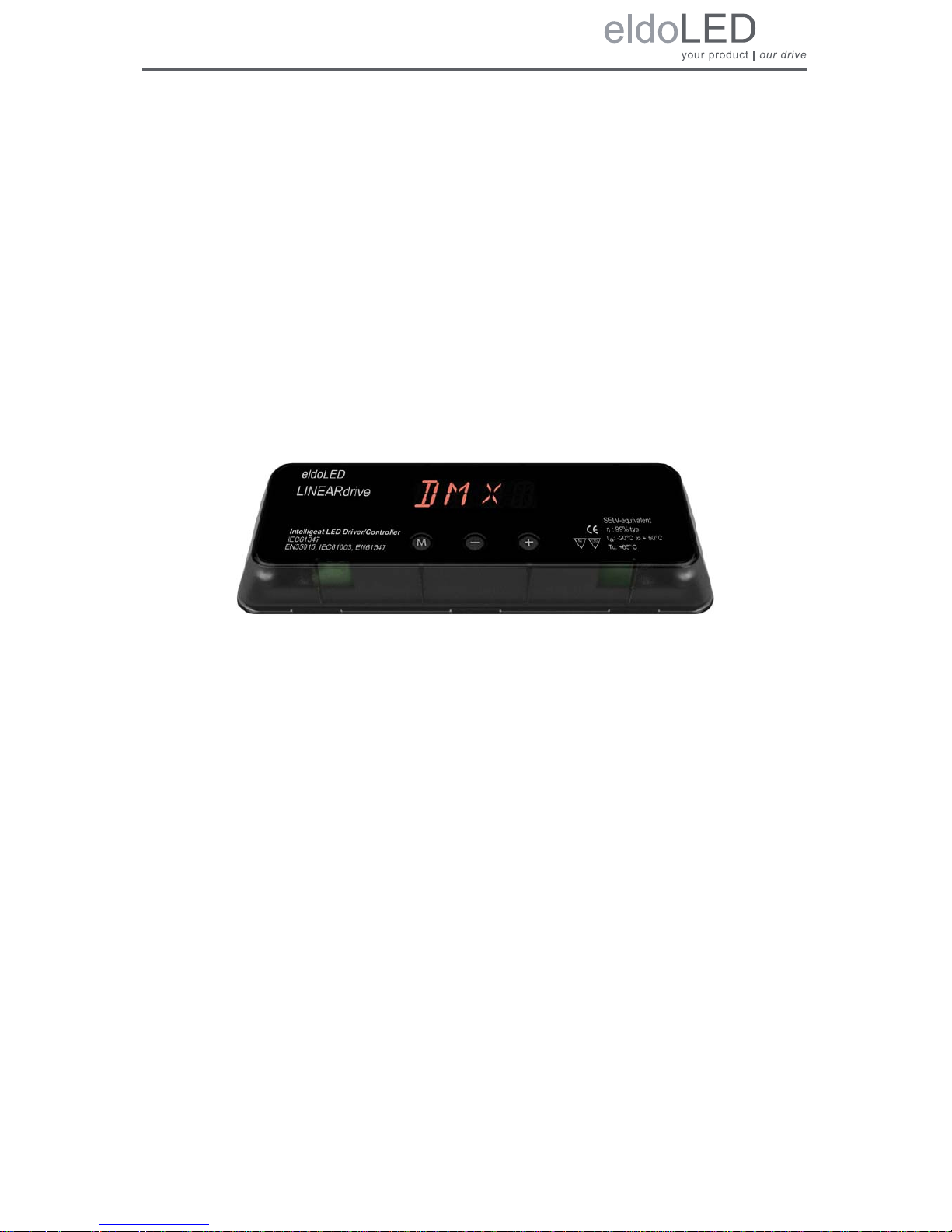
Figure 1.1: LINEARdrive ................................................................................................. 9
Figure 1.2: Creating your own show sequences with eldoLED PC software ................ 10
Figure 1.3: Clearly marked connectors on the LINEARdrive ........................................ 11
Figure 1.4: Strain reliefs on the LINEARdrive ............................................................... 11
Figure 2.1: Removing the cover.................................................................................... 13
Figure 2.2: LINEARdrive’s mounting holes ................................................................... 14
Figure 2.3: Fastening the mounting screws .................................................................. 15
Figure 3.1: Removing the strain reliefs ......................................................................... 19
Figure 3.2: Connecting the leads ................................................................................. 20
Figure 3.3: LINEARdrive Display 180 wiring diagram................................................... 21
Figure 3.4: LINEARdrive Display 720 wiring diagram................................................... 21
Figure 3.5: Connecting LED groups on LINEARdrive 180............................................ 23
Figure 3.6: Connecting LED groups on LINEARdrive 720............................................ 23
Figure 3.7: Fastening the strain reliefs.......................................................................... 24
Figure 4.1: Intuitive user interface................................................................................. 25
Figure 4.2: Setting the mode of operation..................................................................... 27
Figure 4.3: Configuring the LED groups ....................................................................... 28
Figure 4.4: COLR settings for 1-1L and 1-4L................................................................ 30
Figure 4.5: COLR settings for 2-2L and 2-4L................................................................ 30
Figure 4.6: COLR settings for 3-3L ............................................................................... 31
Figure 4.7: COLR settings for 4-4L ............................................................................... 31
Figure 4.8: COLR settings for CCWW or CWWW ........................................................ 32
Figure 4.9: Setting the colour....................................................................................... 33
Figure 4.10: COLR settings for RGB, RRGB or RGGB ................................................ 33
Figure 4.11: COLR settings for RGBW or RGBA .......................................................... 34
Figure 4.12: Setting the colour (left) and adding white or amber (right)....................... 34
Figure 4.13: Configuring show settings......................................................................... 35
Figure 4.14: Configuring DMX network settings for the LINEARdrive 180 (left)
and the LINEARdrive 720 (right)............................................................... 36
Figure 4.15: Viewing DALI network settings ................................................................. 37
Figure 4.16: Locking and unlocking the driver/controller’s configuration ...................... 38
Figure 4.17: Carrying out a test run of the connected LEDs......................................... 39
Figure 4.18: Resetting the driver/controller to its factory default settings ..................... 40
Figure A.1: The LINEARdrive’s dimensions.................................................................. 41

8
Figure A.2: LINEARdrive’s mechanical dimensions...................................................... 42
Figure A.3: Clearly marked connectors......................................................................... 43
9
1 Product description
LINEARdrives are highly integrated, enclosed and easy-to-configure direct voltage controlled
driver/controllers for low-power, indoor LED lighting applications requiring up to 24A.
LINEARdrives can be integrated in a network or used as standalone devices. ShowMaster,
supported on all eldoLED driver/controllers, allows you to upload show sequences for use in
standalone mode. You can create and manage your own show sequences with the eldoLED
TOOLbox and freely available PC software.
LINEARdrives are DMX, DALI and LedSync compatible, allowing up to 15-bit dimming and col-
our control and bidirectional communication for driver configuration and temperature read-out.
Figure 1.1: LINEARdrive
1.1 Setup is a breeze!
Configure the LINEARdrive over its intuitive, 3-button user interface with display. The easy-to-
navigate menu allows you to set parameters such as number of channels, DMX or DALI settings for networked mode and show/colour/dim values for standalone operation. You can also
lock the driver’s configuration and perform a test run of the connected LED groups.
1.2 Robust thermal management
Built-in over temperature protection protects the LINEARdrive against overheating.
10
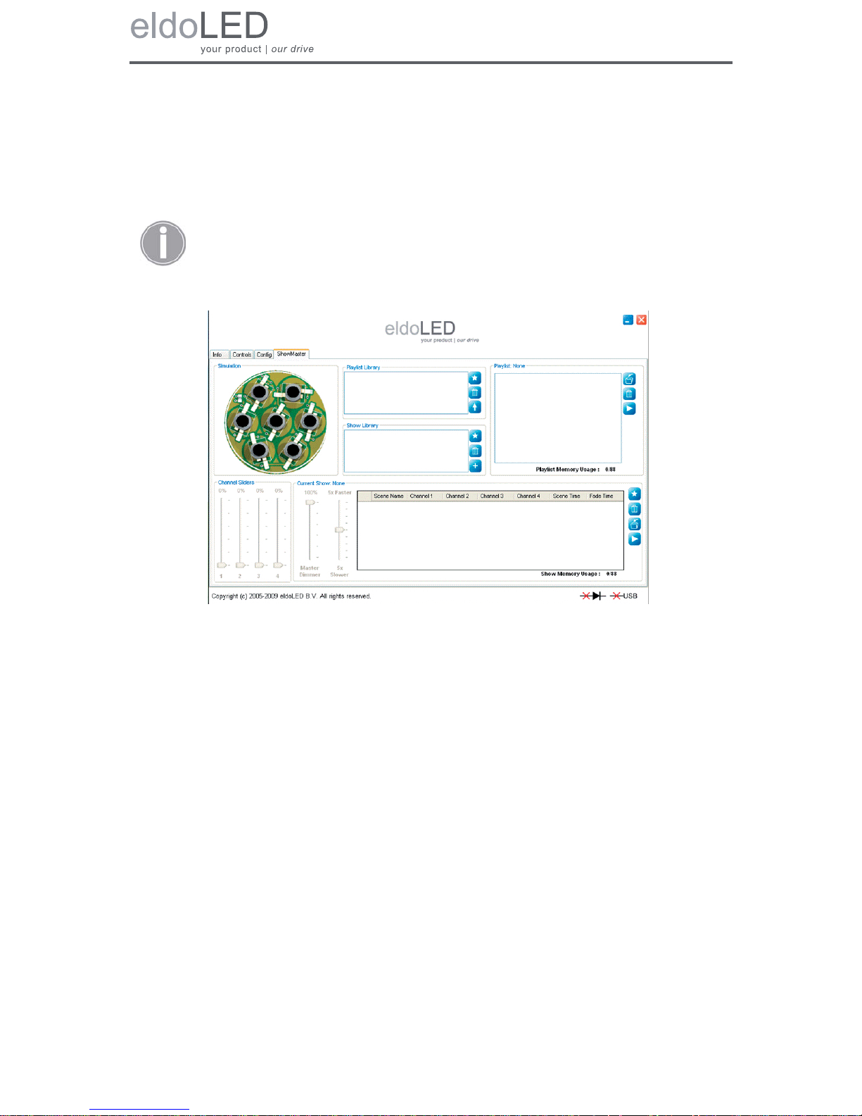
1.3 ShowMaster
ShowMaster, supported on all eldoLED driver/controllers, allows you to upload show sequenc-
es for use in standalone mode. You can create and manage your own show sequences with
the TOOLbox and freely available PC software.
Figure 1.2: Creating your own show sequences with eldoLED PC software
1.4 Low EMI
LINEARdrive’s EMI is very low due to the implementation of slew-rate controlled dimming and
shielded conductors.
Visit www.eldoled.com/software to download the freely available PC software.
11
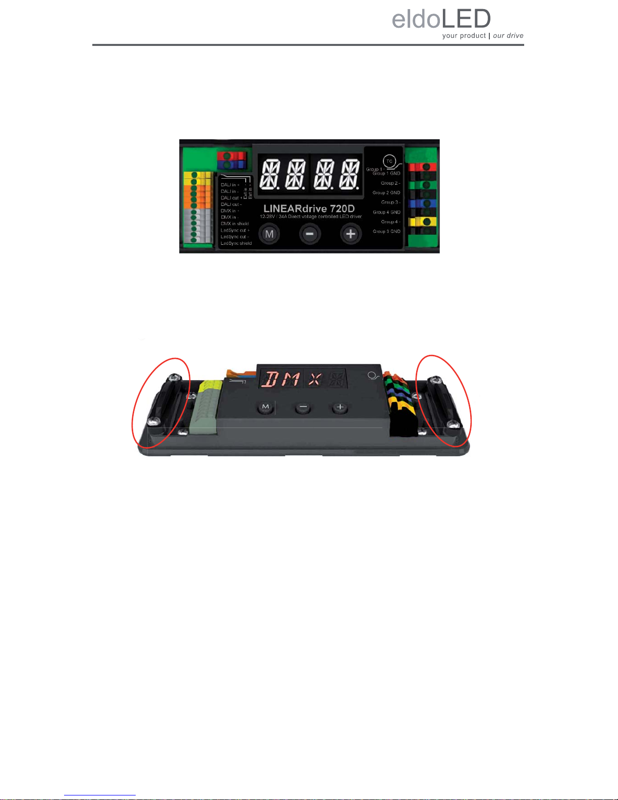
1.5 Easy to connect
Connecting the LINEARdrive is self-explanatory: the spring-cage connectors for LEDs, power
and network leads are all clearly marked.
Figure 1.3: Clearly marked connectors on the LINEARdrive
Strain reliefs prevent leads from being pulled out by accident.
Figure 1.4: Strain reliefs on the LINEARdrive
LINEARdrive 720D
Ext in +
Ext in
DMX in +
DMX in DMX in shield
LedSync out +
LedSync out LedSync shield
-
DALI out -
DALI out +
DALI in -
DALI in +
TC
Group 1
Group 1 GND
Group 2 -
Group 2 GND
Group 3 -
Group 4 GND
Group 4 -
Group 3 GND
12-28V / 24A Direct voltage controlled LED driver

12

13
2 Mounting the driver/controller
2.1 Realizing the right thermal conditions
LINEARdrive 180 can be operated without a heat sink, as its own heat generation always stays
within an acceptable temperature range.
Being the most powerful of its range, LINEARdrive 720 must be mounted onto a heat sink. To
ensure the best possible contact between the LINEARdrive 720 and the heat sink, LINEAR-
drive 720 features a dual heat spreader.
The general rule of thumb you can use when calculating a heat sink’s required dissipating capabilities is that an eldoLED driver/controller adds 10% at the very most to the power consump-
tion of the connected LEDs. In other words, if the connected LEDs consume 90W, the driver/
controller will add a maximum of 9W: the heat sink will have to be able to deal with a total of
99W.
It is recommended to keep ambient temperature values between -20
°C and +50°C (-4°F and
+122
°F). If the ambient temperature exceeds these limits and causes the LINEARdrive to heat
up above normal operating values, its built-in overheating protection will make it shut down.
2.2 Removing the cover
To remove the driver/controller’s cover:
1. Take hold off the driver/controller as indicated by arrow 1 in Figure 2.1: “Removing the
cover”.
2. Pull the cover off the base unit in the upward movement indicated by arrow 2.
Figure 2.1: Removing the cover
1
2
LINEARdrive
Intelligent LED Driver/Controller
I
EC61347
EN55015, IEC61003, EN61547
130
M
SELV-equivalent
: 99% typ
t
a
:
-20°C to + 50°C
: +65°C
Tc

14
2.3 Preparing the mounting surface
LINEARdrive can be mounted onto wood, plastic or metal. If you need to pre-drill mounting
holes into the mounting surface or heat sink:
1. Remove the LINEARdrive’s cover as shown in 2.2 “Removing the cover”.
2. Place the LINEARdrive onto the mounting surface in the desired position.
3. Indicate the position of the mounting holes on the surface by drawing them through
the LINEARdrive’s M4 mounting holes with a pencil.
Figure 2.2: LINEARdrive’s mounting holes
4. Take away the LINEARdrive and pre-drill the screw holes in the mounting surface.
2.4 Fastening the driver/controller to the surface
To fasten the driver/controller to the mounting surface:
1. The driver/controller has four mounting holes suited for M4 screws. Make sure you
have four screws that are appropriate for the surface that you want to mount the driver/
controller onto. Use mounting screws with a minimum length of 15mm.
2. Place the driver/controller in the desired location, matching the LINEARdrive’s mount-
ing holes with the predrilled screw holes on the mounting surface.
3. With a screwdriver, fasten the driver/controller to the surface.
The LINEARdrive’s mechanical dimensions are listed in appendix A “Specifi-
cations”.
The LINEARdrive must be mounted according to the requirements of local
legislation.
M4 mounting hole
M4 mounting hole
M4 mounting hole
M4 mounting hole
TC
Group 1
LINEARdrive 720D
Group 1 GND
Group 2 -
Group 2 GND
Group 3 -
Group 3 GND
Group 4 -
Group 4 GND
Ext in +
Ext in
DMX in +
DMX in DMX in shield
LedSync out +
LedSync out LedSync shield
-
DALI out -
DALI out +
DALI in -
DALI in +
12-28V / 24A Direct voltage controlled LED driver
 Loading...