

Page 1

Eldex
Eldex®
Optos Metering Pumps
Operator’s Manual
Eldex Laboratories, Inc.
30 Executive Court
Napa, CA 94558
Tel: (707) 224-8800
Fax: (707) 224-0688
www.eldex.com
© 2008 Eldex Laboratories, Inc.
Rev. M: 022708
All Rights Reserved
Page 2

Page 3

TABLE OF CONTENTS
CONTENTS PAGE
I. INTRODUCTION 1
Optos Metering Pumps 1
Principles of Operation 1
Materials of Construction 1
About This Manual 1
A Guided Tour of Optos Metering Pumps 2
Specifications 6
Stainless Steel Pump Specifications 6
PEEK Pump Specifications 7
II. INSTALLATION 8
What You Will Need 8
The Unit 8
Tools 8
Unpacking and Location 8
Electrical Connections 8
Power Entry Module 8
Inputs/Outputs 8
Plumbing 9
Solvent Preparation 9
Attaching Inlet Tubing 10
Priming The Pump 10
Attaching Outlet Tubing 10
Pulse Damper Use 10
Using the Piston Wash System 10
III. OPERATION 11
Basic Operation 11
General Notes on Software Operation 11
Setting the Flow Rate 11
Setting the High Pressure Limit 11
Setting the Low Pressure Limit 11
Configuration Screens 12
Setting the Compressibility Compensation Factor 12
Sending the Piston to the Home Position 12
Changing the Refill Rate Setup 12
Setting the Liquid End Type 12
Setting the Remote Control Setting 13
Viewing the EPROM Revision Level 13
Page 4

Advanced Screens 13
Setting the Home Position Offset 13
Setting the Output Function 14
Setting the High/Low Pressure Limit Shutdown 14
Setting the Motor Stall Shutdown 14
Pump Limits 15
Viscosity Limits 15
Chemical Limits 15
Mechanical Limits 15
Temperature Limits 15
Shutdown Procedures 15
IV. MAINTENANCE 16
Cleaning 16
Piston Seals 16
Replacing The Piston Seal 16
Replacing Valves 17
Removal Of Existing Valves 17
Installation Of New Valves 18
Replacing Valve Cartridges 18
Troubleshooting 19
V. SPARE PARTS AND ACCESSORIES 20
For 3/32” Stainless Steel Pumps 20
For 1/8” Stainless Steel Pumps 21
For ¼” Stainless Steel Pumps 22
For 3/32” PEEK Pumps 23
For 1/8” PEEK Pumps 24
For ¼” PEEK Pumps 25
VI. APPENDIX 26
RS232 26
Warranty 27
Return Procedure 27
Trademarks 27
Page 5
CAUTION: The exclamation point within an equilateral triangle is intended to
alert the user to the presence of important operating and maintenance (servicing)
instructions in the literature accompanying the appliance.
ATTENTION: Le point d’exclamation dans un triangle equilatéral signale à
alerter l’utilisateur qu’il y a des instructions d’operation et d’entretien tres
importantes dans la litérature qui accompagne l’appareil.
ACHTUNG: Ein Ausrufungszeichen innerhalb eines gleichwinkeligen Dreiecks
dient dazu, den Benutzer auf wichtige Bedienungs-und Wartungsanweisungen in
der dem Gerät beiliegended Literatur aufmerksam zu machen.
CAUTION: We have tested this pump with 2 propanol. Residual amounts of 2
propanol may be in the pump. You may wish to flush with an appropriate,
miscible solvent.
You may be using a variety of fluids which require special handling procedures
and safety precautions. Consult the appropriate MSDS (Material Safety Data
Sheet) supplied with the materials you will be using. Be certain to follow all
handling, safety, and disposal procedures appropriate for the materials you use.
ATTENTION: Gardez à l’esprit que nous avons testé cette pompe avec le
propanol-2. Les quantités résiduelles du propanol-2 peuvent se trouver sur le
dispositif de raccordement du liquide et vous souhaiterez certainement les
chasser avec un solvant miscible approprié.
Vous pouvez utiliser une variété de liquides qui nécessitent des manipulations et
des précautions particulières. Consultez la fiche technique de sécurité
appropriée; elle est fournie avec le matériel que vous utiliserez. Veillez a bien
respecter toutes les procédures de manipulation, sécurité et élimination du
matériel.
ACHTUNG: Die Pumpe wurde mit 2-Propanol getestet. Geringe Restmengen
von 2-Propanol können sich noch im System befindend, so dass wir Ihnen vor
Inbetriebnahme das Spülen mit einem geeigneten Lösungsmittel empfehlen.
Sie können eine Vielzahl von Lösungsmitteln einsetzen, deren Verwendung unter
Umständen spezielle Sicherheitsvorkehrungen voraussetzt. Bitte beachten Sie
in allen Fällen die, den Lösungsmitteln vom Hersteller beigelegten
Sicherheitsdatenblätter.
Page 6

Page 7
INTRODUCTION
Laboratory and industrial procedures often require metering precise amounts of fluids in a controlled and
reproducible manner. Optos pumps were developed in response to this need. These pumps are capable of
delivering measured amounts of fluids against significant backpressure.
Pump Features Include:
Piston wash chamber for backflushing piston to extend seal life.
Electronic control of piston motion to minimize pulsation.
Optional pulse damper for further pulse reduction.
Easy to use interface for flow setting and other pump parameters.
Metal-free options
Principles of Operation
Optos pumps attain precise metering at intermediate and high pressures by a positive displacement, reciprocating
piston. The piston is driven by a stepper motor via an eccentric. Advanced software algorithms control motor
speed based on piston position, achieving rapid fluid intake and smooth, constant fluid delivery, minimizing
pulsation. Additional reductions of pulsation can be achieved by use of the optional damper.
Ball and seat inlet and outlet valves ensure precise metering. The suction created by the piston retracting to refill
the piston chamber pulls the inlet ball off the inlet seat allowing fluid to travel through the inlet check valve.
Simultaneously, the outlet ball is pulled back onto its‟ seat, preventing fluid from exiting the piston chamber.
During the delivery portion of the piston‟s duty cycle, the inlet ball is pushed back onto its‟ seat as the piston
moves forward, preventing fluid from travelling back to the pump reservoir. Simultaneously, the outlet ball is
forced off its‟ seat, allowing fluid to exit the outlet valve. For the valves to operate effectively, a pressure
differential of at least 25 psi is required on the outlet side of the pump.
The pump‟s flow rate is set directly in mL/min. using the up and down buttons on the user interface. Flow rates
are determined by piston displacement (diameter, and stroke length) and motor speed.
Some Optos pumps may be fitted with a pulse damper. The damper is a diaphragm type damper, where a
diaphragm made of an inert material flexes against a compressible fluid (spiked with red dye), thereby absorbing
pulses in fluid delivery. To maximize the damper‟s efficiency, the system should operate against at least 500 psi.
If your system does not normally generate such pressures and you wish to increase the efficiency of the damper,
you can install a backpressure device, or some narrow ID tubing downstream of the pump.
Materials of Construction
The materials used for the liquid end of your Optos Pump were carefully chosen for corrosion resistance. The
piston is sapphire, and the inlet and outlet valves incorporate sapphire seats and ruby balls.
The piston seal material is made from specially formulated PTFE and has excellent chemical compatibility
characteristics.
The liquid end housing is made of passivated type 316 stainless steel because of its superior resistance to
corrosion. In applications requiring the use of chemicals corrosive to type 316 stainless steel, you may order a
PEEK (polyetheretherketone) liquid end.
About This Manual
This manual provides instructions and information on Optos metering pumps.
Section II of this manual, beginning on page 8, describes the unpacking, location, and initial installation of your
metering pump. Section III, beginning on page 11, describes the operation of the Optos hardware and the menu
system in detail.. Section IV, beginning on page 16, describes maintenance procedures. Section V, beginning on
page 20, contains appendixes, including, lists spare parts and accessories for the various pump models.
1
Page 8

A Guided Tour of the Optos Metering Pumps
Front Panel
As you look at the front panel of your Optos Metering Pump (Figure 1.1), you will see:
Component Details
Local Interface:
1. Liquid Crystal Display (LCD). Displays flow rate, pressure (with optional pulse damper), other
allowed functions.
2. Up/Down Keys. UP and DOWN arrow keys set flow rates, change pump settings.
3. Permanent Functions Keys. DISPLAY, ΔMENU, and RUN/STOP keys are control keys permanently
defined for direct control of major instrument functions.
4. Status LEDs. Indicate pump running or fault.
Pulse Damper: optional pulse damper for minimized fluid delivery pulsation.
5. Outlet Port: Connection to downstream device.
6. Inlet Port: Connection from pump outlet.
Liquid End Assembly:
7. Outlet Valve: Provides tubing connection for pump output.
8. Cylinder: Contains pumping chamber and piston wash ports.
9. Inlet Valve: Provides tubing connection to fluid source. Inlet valve has an additional groove on
the hexagonal portion of the valve.
Rear Panel
As you look at the rear panel of your Optos Metering Pump (Figure 1.2), you will see:
Component Details
1. RS232: RJ11 connector for RS232 communication.
2. I/O: Input/output connections for remote analog control, pressure out, error out, remote start, stop.
3. Power Entry: Provides power connection with modular cord.
4. Fuse: Housing for pump fuses.
5. On/Off: Turns the power to the pump on and off.
2
Page 9
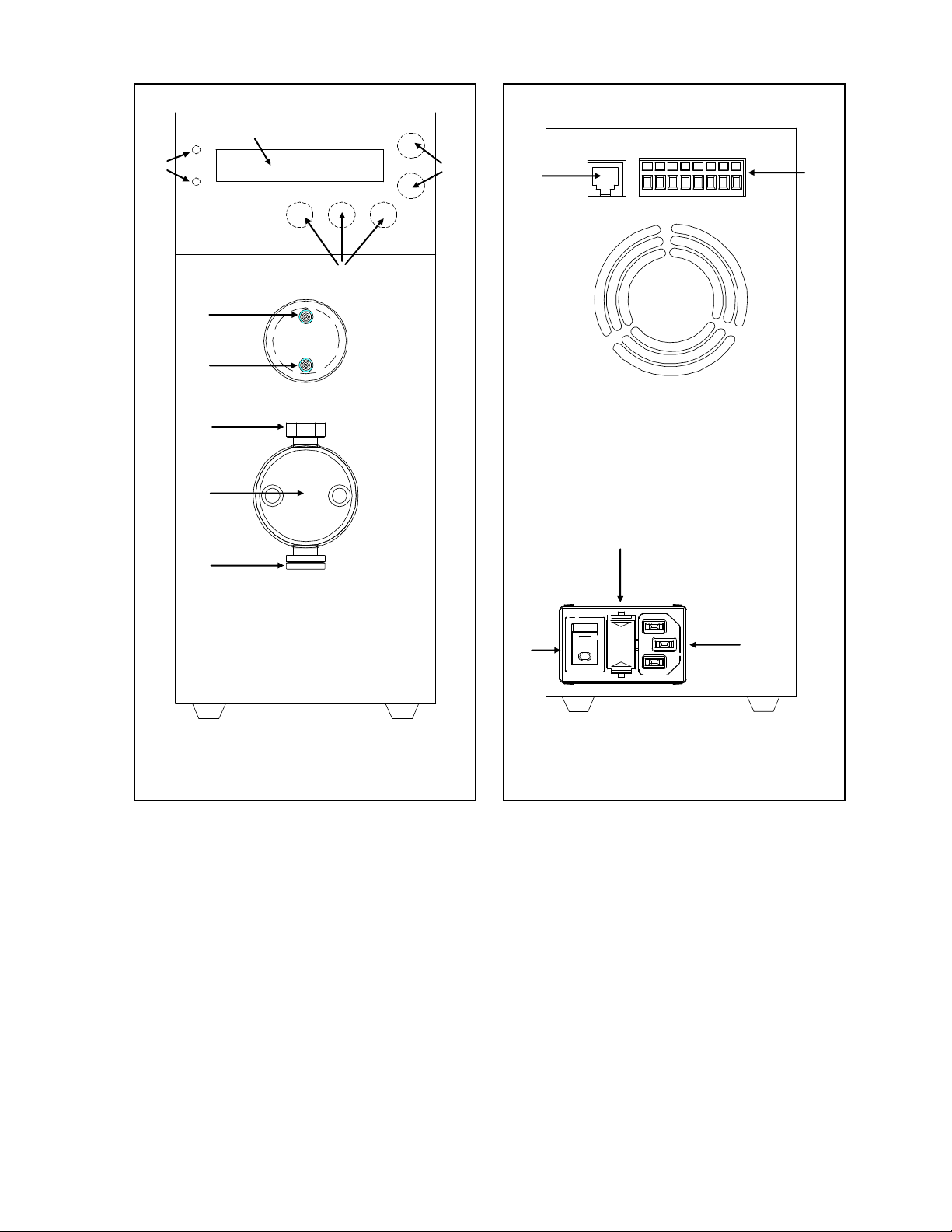
Figure 1.1: Front View of Optos
Figure 1.2: Rear View of Optos
1
2
3
4
5
6 7 8
9
1
2 3 4
5
3
Page 10
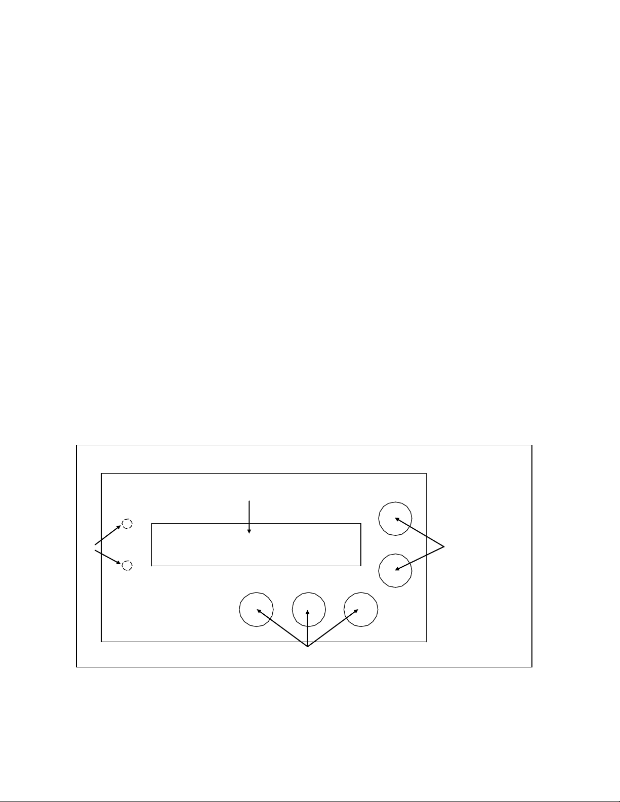
Figure 1.3: Local Interface
1
2
3
4
An Overall Look at the Local Interface
Operation of the Optos Pump is controlled from a series of menus and there is no need to remember esoteric
control codes or command sequences. A detailed description of the menu sequence is given in Section III.
As you look at the local interface (Figure 1.3), you will see:
Component Details
1. Status LEDs: Upper green LED indicates pump is running; lower red LED indicates a pump fault (for
example, an overpressure limit, or motor stall condition.
2. Display: A one line, 16 character LCD display is used to provide readout of flow and pressure (with
optional pulse damper), and access to pump functions.
3. Up/Down Keys: UP and DOWN arrow keys set flow rates, pressure limits (with optional pulse damper),
and function settings.
4. Permanent Function Keys: ΔMENU key changes the display to different pump functions, DISPLAY key
toggles display back to main display of flow, or flow and pressure (with optional pulse damper),
RUN/STOP key runs the pump and stops the pump.
Key Definitions
ΔMENU: The ΔMENU (Change Menu) key scrolls through the main menu selections.
DISPLAY: The DISPLAY key toggles back to main display of flow, or flow and pressure (with optional pulse
damper).
UP/DOWN: UP and DOWN arrow keys increase or decrease flow rate setting, high or low pressure limit settings,
and change setting of other pump parameters.
DISPLAY, then ΔMENU: Holding down the DISPLAY key followed by pressing the ΔMENU key brings up a series
of sub menus which pertain to various pump settings. Pressing the DISPLAY key alone returns to main display.
ΔMENU, then DISPLAY: Holding down the ΔMENU followed by pressing the DISPLAY key brings up a series of
sub menus which pertain to obscure pump settings. Pressing the DISPLAY key alone returns to main display.
4
Page 11
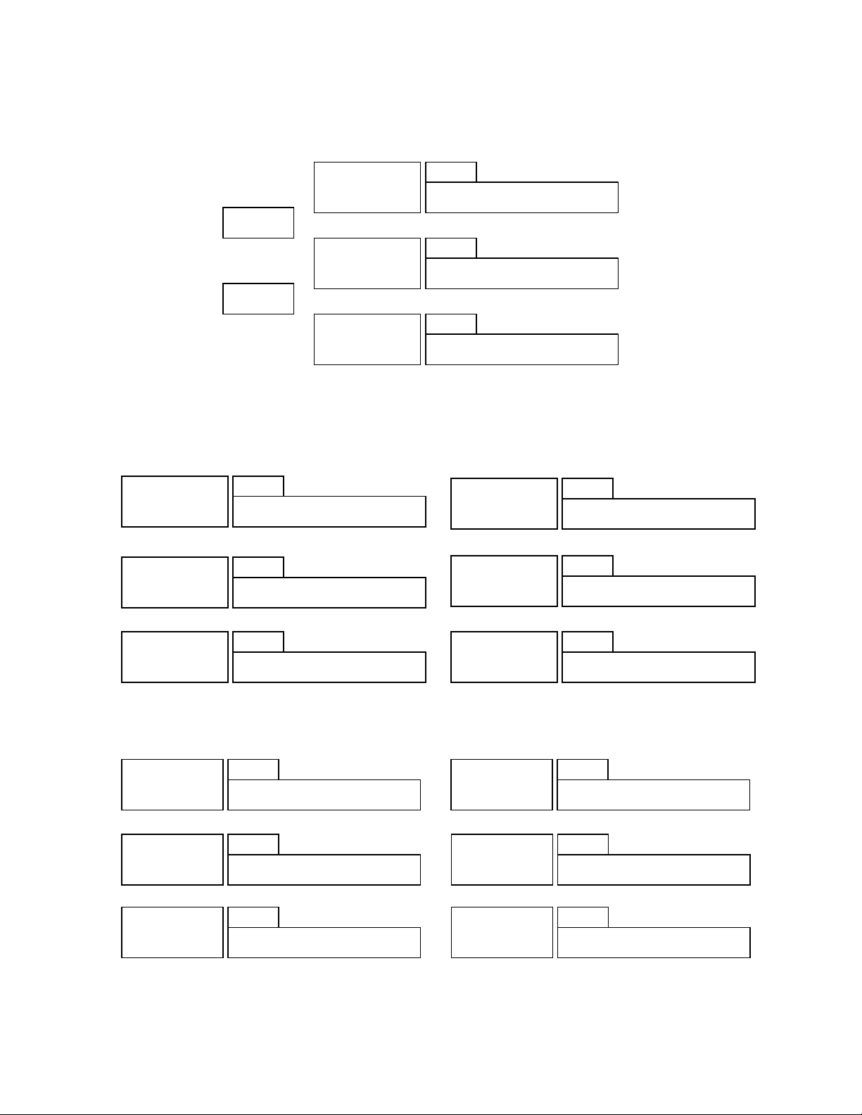
XX.XXXmL XXXXpsi
MAIN
HI LIMIT: XXXX
H
LO LIMIT: XXXX
L
GO HOME: HIT RUN
HP
COMPRESS: XX
C
REFILL: FULL OUT
R
HEAD: 1/8 SS
LE
REMOTE: OFF
REM
VERSION: X.XX
V
HOME OFFSET: XX
HO
0-5V OUT: PRESS
S
STOP STALL: ON
SS
PRESS LIMIT: ENA
LI
Read/set flow
rate
Read pressure
Set high
pressure limit
Set low pressure
limit
Adjust
compressibility
compensation
Set refill:output
ratio
View EPROM
level
Set remote
control
configuration
Set piston &
materials of
pump
Send piston to
forward position
Set pressure
limit ON/OFF
Set motor stall
ON/OFF
View/set
voltage out
Set home
position offset
ΔMENU
ΔMENU
PRESS 0: HIT RUN
XDC
Zero Pressure
Transducer
STROKE: .125
ST
View stroke
length
Menu Schematic
The menu schematic indicates the general structure of the menu map. The specific screens shown may vary
from your specific configuration.
Basic Screens
Configuration Screens: DISPLAY & ΔMENU
Advanced Screens: ΔMENU & DISPLAY
5
Page 12
Model
Flow Rate
Range (min.to
max.) mL/min.
Max
Pressure
(psi)
Piston
Diameter
(inches)
Max.
Piston
Stroke
Piston
Displacement
Electrical
VA
Dimensions (L x W
x H inches)
Weight
(lbs.)
1LM
0.002 - 2.5
6000
.093
.125”
.014 mL
100-230V;
50/60Hz
80
9.5 x 4 x 9
12
1LMP
0.002 - 2.5
6000
.093
.125”
.014 mL
100-230V;
50/60Hz
80
9.5 x 4 x 9
12
1SM
0.003 - 5.0
6000
.125
.125”
.025 mL
100-230V;
50/60Hz
80
9.5 x 4 x 9
12
1SMP
0.003 - 5.0
6000
.125
.125”
.025 mL
100-230V;
50/60Hz
80
9.5 x 4 x 9
12
1HM
0.01 - 20.0
3000
.250
.125”
.1 mL
100-230V;
50/60Hz
80
9.5 x 4 x 9
12
Model
Flow Rate
Range (min.to
max.) mL/min.
Max
Pressure
(psi)
Piston
Diameter
(inches)
Max.
Piston
Stroke
Piston
Displacement
Electrical
VA
Dimensions (L x W
x H inches)
Weight
(lbs.)
2LM
0.003 - 5.0
6000
.093
.250”
.028 mL
100-230V;
50/60Hz
80
9.5 x 4 x 9
12
2LMP
0.003 - 5.0
6000
.093
.250”
.028 mL
100-230V;
50/60Hz
80
9.5 x 4 x 9
12
2SM
0.01 - 10.0
6000
.125
.250”
.05 mL
100-230V;
50/60Hz
80
9.5 x 4 x 9
12
2SMP
0.01 - 10.0
6000
.125
.250”
.05 mL
100-230V;
50/60Hz
80
9.5 x 4 x 9
12
2HM
0.02 - 40.0
1500
.250
.250”
.2 mL
100-230V;
50/60Hz
80
9.5 x 4 x 9
12
Model
Flow Rate
Range (min.to
max.) mL/min.
Max
Pressure
(psi)
Piston
Diameter
(inches)
Max.
Piston
Stroke
Piston
Displacement
Electrical
VA
Dimensions
(L x W x H inches)
Weight
(lbs.)
3LM
0.01 - 10.0
3000
.093
.500”
.057 mL
100-230V;
50/60Hz
80
9.5 x 4 x 9
12
3SM
0.01 - 20.0
1500
.125
.500”
.1 mL
100-230V;
50/60Hz
80
9.5 x 4 x 9
12
3HM
0.04 - 80.0
750
.250
.500”
.4 mL
100-230V;
50/60Hz
80
9.5 x 4 x 9
12
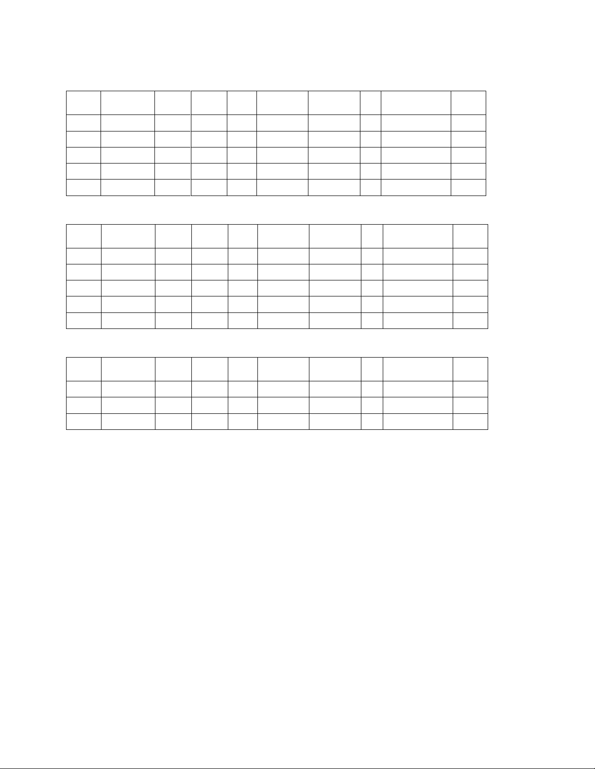
Specifications
Stainless Steel Optos/Model 1 Pump Specifications
Stainless Steel Optos/Model 2 Pump Specifications
Stainless Steel Optos/Model 3 Pump Specifications
Maximum flow rate specifications are based on the theoretical volume displacement; actual flow rates will vary depending on such factors as fluid viscosity, compressibility, and
temperature.
Common Specifications:
Wetted Parts: Type 316 stainless steel, PTFE, CTFE, sapphire, ruby
Reproducibility: ±0.3% typical
Tubing Connections: Inlet valve: ¼” –28 plastic fitting for 1/8” Teflon® tubing
Outlet valve: 1/16” I.D. ferrule and tube nut, 10-32 thread
Pumps with .250” pistons use 1/8” Swagelok connections on the inlet and outlet
Other connections available on request
Viscosity Limit: 500 Centipoise
Fuses: .63 A
Operating Environment:
Temperature: 5 – 35ºC
Maximum Humidity: 85%, non-condensing
Maximum Altitude: 2,000 meters
Optional Damper
Type: Diaphragm
Wetted Parts: Type 316 stainless steel, Kalrez
valves
6
Page 13

Model
Flow Rate
Range (min.to
max.) mL/min.
Max
Pressure
(psi)
Piston
Diameter
(inches)
Max.
Piston
Stroke
Piston
Displacement
Electrical
VA
Dimensions (L x W
x H inches)
Weight
(lbs.)
1LI
0.002 - 2.5
6000
.093
.125”
.014 mL
100-230V;
50/60Hz
80
9.5 x 4 x 9
12
1LIP
0.002 - 2.5
6000
.093
.125”
.014 mL
100-230V;
50/60Hz
80
9.5 x 4 x 9
12
1SI
0.003 - 5.0
6000
.125
.125”
.025 mL
100-230V;
50/60Hz
80
9.5 x 4 x 9
12
1SIP
0.003 - 5.0
6000
.125
.125”
.025 mL
100-230V;
50/60Hz
80
9.5 x 4 x 9
12
1HI
0.01 - 20.0
3000
.250
.125”
.1 mL
100-230V;
50/60Hz
80
9.5 x 4 x 9
12
Model
Flow Rate
Range (min.to
max.) mL/min.
Max
Pressure
(psi)
Piston
Diameter
(inches)
Max.
Piston
Stroke
Piston
Displacement
Electrical
VA
Dimensions (L x W
x H inches)
Weight
(lbs.)
2LI
0.003 - 5.0
6000
.093
.250”
.028 mL
100-230V;
50/60Hz
80
9.5 x 4 x 9
12
2LIP
0.003 - 5.0
6000
.093
.250”
.028 mL
100-230V;
50/60Hz
80
9.5 x 4 x 9
12
2SI
0.01 - 10.0
6000
.125
.250”
.05 mL
100-230V;
50/60Hz
80
9.5 x 4 x 9
12
2SIP
0.01 - 10.0
6000
.125
.250”
.05 mL
100-230V;
50/60Hz
80
9.5 x 4 x 9
12
2HI
0.02 - 40.0
1500
.250
.250”
.2 mL
100-230V;
50/60Hz
80
9.5 x 4 x 9
12
Model
Flow Rate
Range (min.to
max.) mL/min.
Max
Pressure
(psi)
Piston
Diameter
(inches)
Max.
Piston
Stroke
Piston
Displacement
Electrical
VA
Dimensions
(L x W x H inches)
Weight
(lbs.)
3LI
0.01 - 10.0
3000
.093
.500”
.057 mL
100-230V;
50/60Hz
80
9.5 x 4 x 9
12
3SI
0.01 - 20.0
1500
.125
.500”
.1 mL
100-230V;
50/60Hz
80
9.5 x 4 x 9
12
3HI
0.04 - 80.0
750
.250
.500”
.4 mL
100-230V;
50/60Hz
80
9.5 x 4 x 9
12
PEEK Optos/Model 1 Pump Specifications
PEEK Optos/Model 2 Pump Specifications
PEEK Optos/Model 3 Pump Specifications
Maximum flow rate specifications are based on the theoretical volume displacement; actual flow rates will vary depending on such factors as fluid viscosity, compressibility, and
temperature.
Common Specifications:
Wetted Parts: PEEK, UHMW Polyethylene, CTFE, sapphire, ruby
Reproducibility: ±0.3% typical
Tubing Connections: Inlet valve: ¼” –28 plastic fitting for 1/8” Teflon® tubing
Outlet valve: 1/16” I.D. ferrule and tube nut, ¼-28 thread
Other connections available on request
Viscosity Limit: 500 Centipoise
Fuses: .63 A
Operating Environment:
Temperature: 5 – 35ºC
Maximum Humidity: 85%, non-condensing
Maximum Altitude: 2,000 meters
Optional Damper
Type: Diaphragm
Wetted Parts: PEEK, Kalrez
7
Page 14
CAUTION: We have tested this pump with 2 propanol. Residual amounts of 2
propanol may be in the pump. You may wish to flush with an appropriate,
miscible solvent.
You may be using a variety of fluids which require special handling procedures
and safety precautions. Consult the appropriate MSDS (Material Safety Data
Sheet) supplied with the materials you will be using. Be certain to follow all
handling, safety, and disposal procedures appropriate for the materials you use.
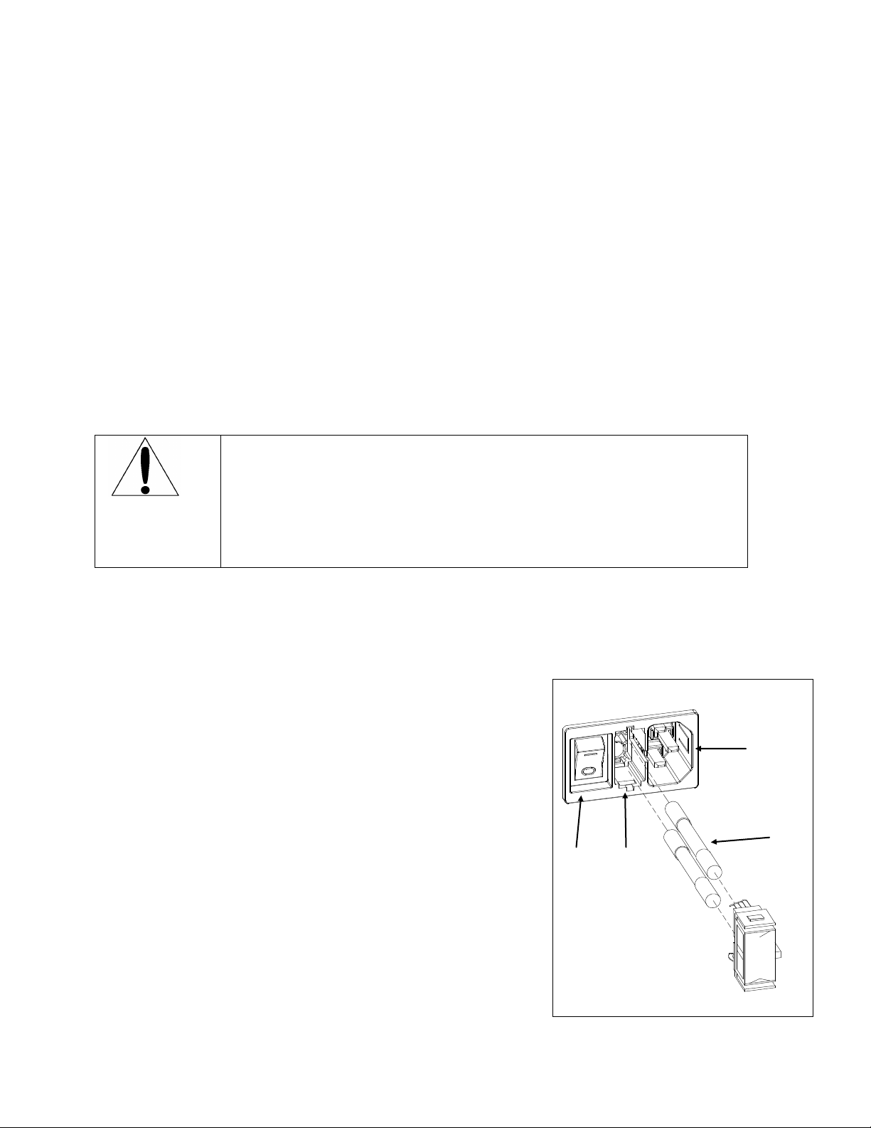
Figure 2.1: Power Entry Module
1
2
3
4
INSTALLATION
What You Will Need
The Unit
A Optos Pump consists of the pump assembly, a fittings kit for tubing connections (except for ¼” piston
stainless steel pumps, which have fittings attached to the valves), a syringe (except ¼” pumps), a power cord,
this manual and warranty card.
Tools
You will not need special tools for the routine use of your OptosPump. For installation, all you will need are a
few wrenches to attach the fittings and perhaps a small blade screwdriver if you are making I/O connections.
The tool sizes you will need will depend on the specific fittings used (and are referenced in the appropriate
section of the instruction manual). If you have not already ordered a Preventive Maintenance Kit, we suggest
you consider doing so now. A listing of the various PM Kits beings on page 17.
Unpacking and Location
Before attempting to operate your pump, unpack it carefully. You should not discard any packing material, as
you will want to re-use it for storage and shipping. If any damage is evident from improper handling from
shipping, you should contact the freight company that delivered the unit to file a claim.
You must use your Optos Pump in a clean, well ventilated and dust free environment, free of corrosive or
explosive vapors. Optos Pumps are designed for table top use; you should not install your pump on the floor.
Your Optos Pump must be operated in a horizontal position. Safety may be impaired if use of your Optos pump
is not as instructed.
Electrical Connections
Power Entry Module
As you look at the Power Entry Module (Figure 2.1), you will see:
1. ON/OFF Switch
2. Fuse Drawer
The power cord is plugged into the power inlet. Plug the power cord of the
pump into a grounded, properly rated outlet and turn the power switch to
ON. The power is turned on by positioning the ON/OFF switch so the “1”
is depressed. After you have confirmed there is electrical power, turn the
power off by positioning the ON/OFF switch so the “0” is depressed.
3. Power Inlet
4. Fuses
Inputs/Outputs
I/O functions are available on the connector on the rear panel. To wire the
I/O connector for inputs or outputs, use a small screwdriver to depress the
lever in the upper port of the I/O connector; this will open the lower port of
the I/O connector. Insert the wire and release the upper port lever.
8
Page 15
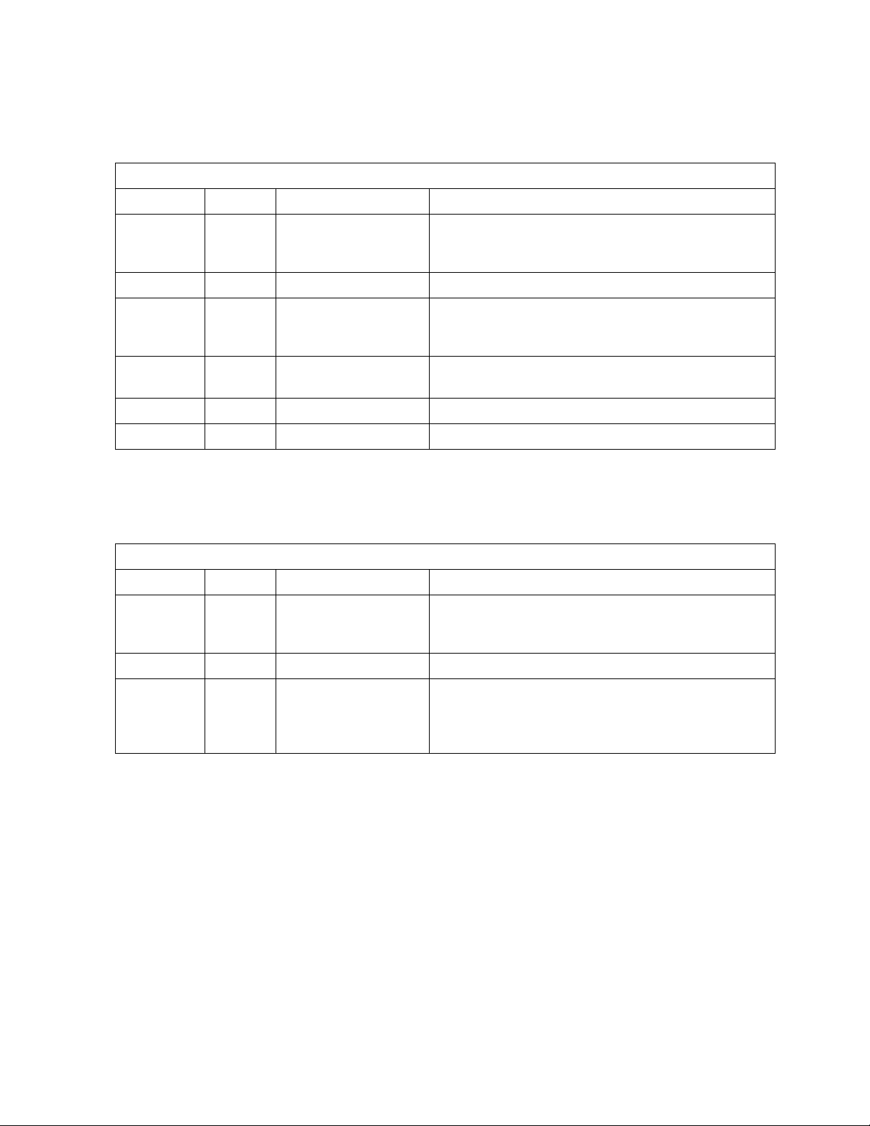
Table 2.1
I/O Position
Label
Function
Description
1
4-20mA
4-20mA current loop
Allows for remote control of flow rate using a 4-20mA
current loop. Wire signal to position 1 and common to
position 2.
2
Common
Common
Used in conjunction with position 1.
3
5VDC
5 VDC
Allows for remote control of flow rate using a 0-5VDC
control. Wire signal to position 3 and common to
position 5.
5
GND
Ground
Ground position for use in conjunction with position 3, 6
or position 7.
6
RUN
Run pump
Contact closure, starts running pump at set flow rate.
7
STOP
Stop pump
Contact closure, stops pump.
Table 2.2
I/O Position
Label
Function
Description
4
PRESS
Output of pressure
0-5 VDC ouput of pressure (when optional damper is
installed), or flow. Signal output is on position 4; use
with ground on position 5.
5
GND
Ground
Used in conjunction with position 4 or position 8.
8
ERROR
Error output
TTL low output indicating pump error (pressure limit
violation when used with optional damper; motor stall).
Signal output is on position 8; use with ground on
position 5.
Inputs
The Optos can be remotely controlled from devices which can send current loop or voltage signals. In addition,
the Optos can be remotely controlled using contact closures. The remote inputs available are defined in Table
2.1:
Outputs
The Optos can send contact closures and an analog signal to remote devices. The remote outputs available are
defined in Table 2.2:
RS232
The RJ11 connector on the rear panel provides an RS232 communication port. For details on use of the RS232,
consult Section V.
Plumbing
Solvent Preparation
Solvent Degassing
We strongly recommend you degass the fluid prior to using it to prevent cavitation. There are many means of
degassing the fluid, including ultrasonication and vacuum systems. Many users find helium sparging convenient
and effective. The usual procedure is to sparge the solvent vigorously for 15 minutes or so and then maintain a
trickle of helium during solvent use. Some users blanket the reservoir with helium after sparging (pressurize
reservoirs to about 3 psi with helium).
9
Page 16
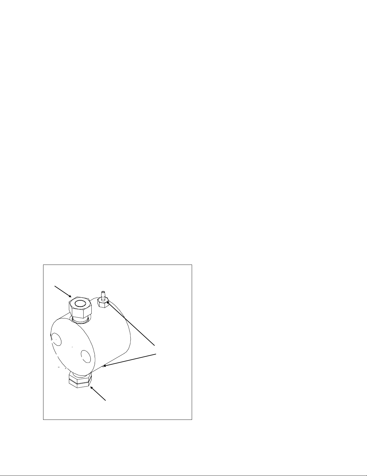
Figure 2.2: Liquid End Assembly
Wash Ports
Inlet Valve
Outlet Valve
Solvent Filtration
You must filter your solvents. We recommend you install a 10 micron sintered stainless steel filter (P/N 5776)
on the inlet line. When you wish to avoid metal, a 10 micron plastic filter is available (P/N 1279).
Attaching Inlet Tubing
Most Optos pumps come supplied with a fittings kit, which includes inlet tubing, as well as inlet and outlet nuts
and ferrules. Attach the 1/8” Teflon tubing to the inlet valve. Hand tighten the nut onto the valve.
Optos stainless steel pumps with ¼” diameter pistons use 1/8” Swagelok® fittings on the inlet and outlet valves
and use 1/8” tubing (not supplied) and require a 7/16” wrench to tighten the fittings and a ½” wrench to tighten
the valves.
Priming the Pump
After you attach the inlet tubing to the pump, place the other end of the tubing in a reservoir of the liquid you
will be pumping. Be certain you completely submerge the end of the tubing (or the filter) in the liquid. Insert
the syringe into the outlet (top) valve opening. You should exercise care when handling the syringe. Improper
use can cause the syringe to break off in the valve (and you will have to install a new valve).
Turn the power switch to ON, set a flow rate (usually, for priming, an elevated flow is desireable) and press the
run key. Manually draw a few milliliters of fluid into the syringe. Remove the syringe and look at the valve
opening. There should not be traces of air bubbles. If the air bubbles persist, turn off the pump, check the liquid
level in the reservoir and the tightness of the inlet fitting. If the inlet tubing is above the surface of the liquid, or
if the inlet fitting is loose, you will need to correct the condition and repeat the priming procedure. When the
pump is primed, press the stop key.
Attach Outlet Tubing to Pump (if required)
With a ¼” wrench, attach 1/16” tubing (not supplied) to the outlet (top) valve using the tube nut and ferrule. Do
not set the ferrule in the valve, since doing so may compress and damage the valve components. Instead, set the
ferrule onto the tubing in a column or similar non-compressible fixture. Always stabilize the valve housing with
a ½” wrench when attaching fittings. Never tighten fittings to beyond 40 in./lbs., or the point where no leakage
occurs. Excessive force in tightening fittings can result in valve compression and damage. On PEEK® pumps,
the fitting on the outlet valve is hand tightened.
Optos stainless steel pumps with ¼” pistons use
1/8” Swagelok® fittings on the inlet and outlet
valves and use 1/8” tubing (not supplied) and
require a 7/16” wrench to tighten the fittings and
a ½” wrench to tight the valves.
Pulse Damper Use (optional
damper on Optos pumps with .093
or .125 pistons)
Optos pumps provided with a pulse damper have
a line already connected between the pump
outlet and the damper inlet. Priming the system
is achieved in the same way as outlined above,
except the syringe is attached to the outlet port
of the damper.
Attaching outlet tubing to the outlet port of the
damper is achieved in the same way as outlined
above. Excessive force in tightening fittings can
damage the damper, which is expensive to
replace.
Using the Piston Wash system
The use of buffers or solutions which crystallize when exposed to air can lead to abrasion of the piston seal.
Optos pumps have a built-in wash chamber. The wash system is designed to flush the back end of the primary
piston seal. By using the wash system, you can significantly extend the life of the piston seal (particularly when
10
Page 17

pumping salt solutions). Your choice of a wash solution depends on the nature of the fluid being pumped
(usually a mixture of water with 20% methanol is suggested).
The pump cylinder has two barbed fittings installed. Usually, the lower fitting is used as the wash inlet and the
upper fitting is used as the wash outlet. Attach 1/8” ID tubing to the inlet and outlet ports of the wash system. A
common means of employing the wash system is to use a syringe attached to the wash outlet tubing to pull fluid
into the wash chamber (when fluid comes out the outlet port, you know you have filled the wash chamber). We
recommend flushing the wash chamber periodically to minimize piston seal abrasion.. Alternatively, you could
deliver fluid continuously through the wash system by circulating the wash solution with a pump.
11
Page 18
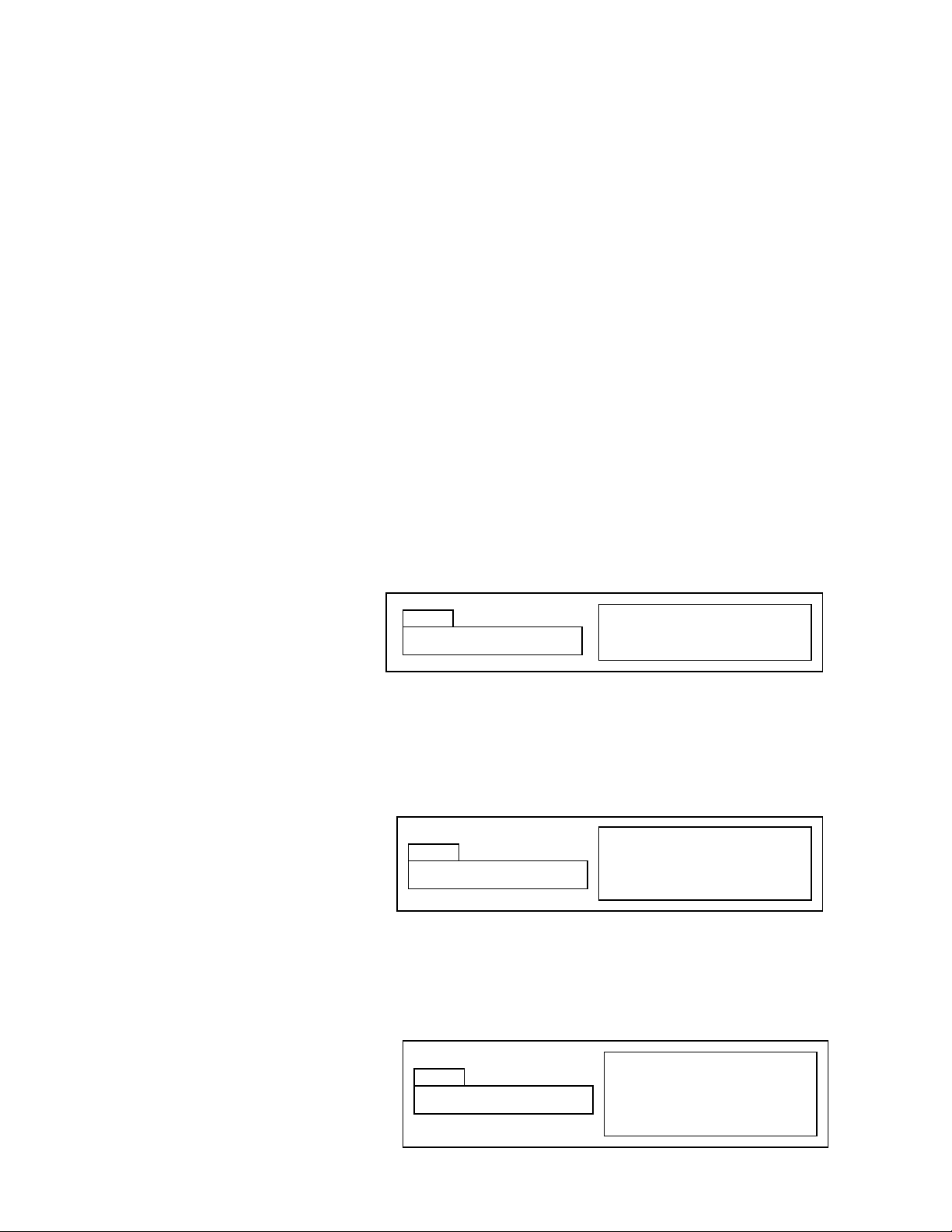
Turn power ON
Use UP and DOWN keys to set
Press RUN/STOP key to run pump
XX.XXXmL XXXXpsi
MAIN
HI LIMIT: XXXX
H
Press ΔMENU key
Use UP and DOWN keys to set
Press DISPLAY key to return to
main display
LO LIMIT: XXXX
L
Press ΔMENU key (twice from
main display)
Use UP and DOWN keys to set
Press DISPLAY key to return to
main display
OPERATION
Basic Operation
Optos pumps perform more reproducibly if there is some degree of backpressure (preferably at least 25 psi). In
all cases, outlet resistance must exceed inlet pressure. Otherwise, the fluid will simply flow through the pump
without being metered. If the system in which the pump is being used does not generate enough backpressure,
we suggest you install a device, e.g., a “dummy” column or a backpressure regulator, to artificially maintain the
appropriate backpressure. The ideal setup for the pump is where there is a little positive pressure on the inlet
side of the pump (achieved by elevating or pressurizing the reservoir) to minimize cavitation, and substantially
greater outlet pressure to maximize valve efficiency.
General Notes on Software Operation
The Optos pumps have intuitive software control. Three separate levels of software control can be accessed.
The most common commands, setting the flow rate and the high and low pressure limits, are accessed either
from the main display screen, or by pressing the ΔMENU key (the ΔMENU key will cycle through commands for
each level of software control). More infrequently used commands are accessed by holding down the DISPLAY
key and pressing the ΔMENU key (commands which send the piston to the home position, setting the
compressibility compensation factor, setting the refill/output ratio, changing the liquid end type, setting the
remote mode, and viewing the EPROM revision). Least frequently used commands are accessed by holding
down the ΔMENU key and pressing the DISPLAY key (commands which set the home offset, voltage output,
whether the high and low pressure limits will be activated, and the stall stop condition).
The UP and DOWN keys change the setting of the various parameters. When the setting is numeric, the longer the
key is held down, the faster the value changes. The DISPLAY key returns to the main display of flow (and
pressure when the optional damper is installed).
Setting the Flow Rate
When the power is turned ON, the
display shows the set flow rate (and
pressure when the optional damper is
installed).
To set the flow rate, press the UP arrow
key to increase the flow set point, press the DOWN arrow key to decrease the flow set point. The longer you hold
down the up or down arrow, the faster the display scrolls through flow settings. To run the pump at the flow set
point, press the RUN/STOP key. The green LED will be illuminated when the pump is running.
Setting the High Pressure Limit
Optos pumps fitted with a pulse damper
are able to have high pressure limits set.
The default setting is the maximum
pressure capability of the model. To
change the setting, press the ΔMENU key
once. Use the UP or DOWN arrow key to
increase or decrease the high pressure limit. To return to the main screen, press the DISPLAY key.
When the high pressure limit is violated, the pump stops running, the lower red LED lights and the display
shows HI PRESS XXXX.
Setting the Low Pressure Limit
Optos pumps fitted with a pulse damper are
able to have low pressure limits set.
The default setting is the zero psi. The
maximum setting is 50 psi less than the high
pressure limit. To change the setting, press
12
Page 19
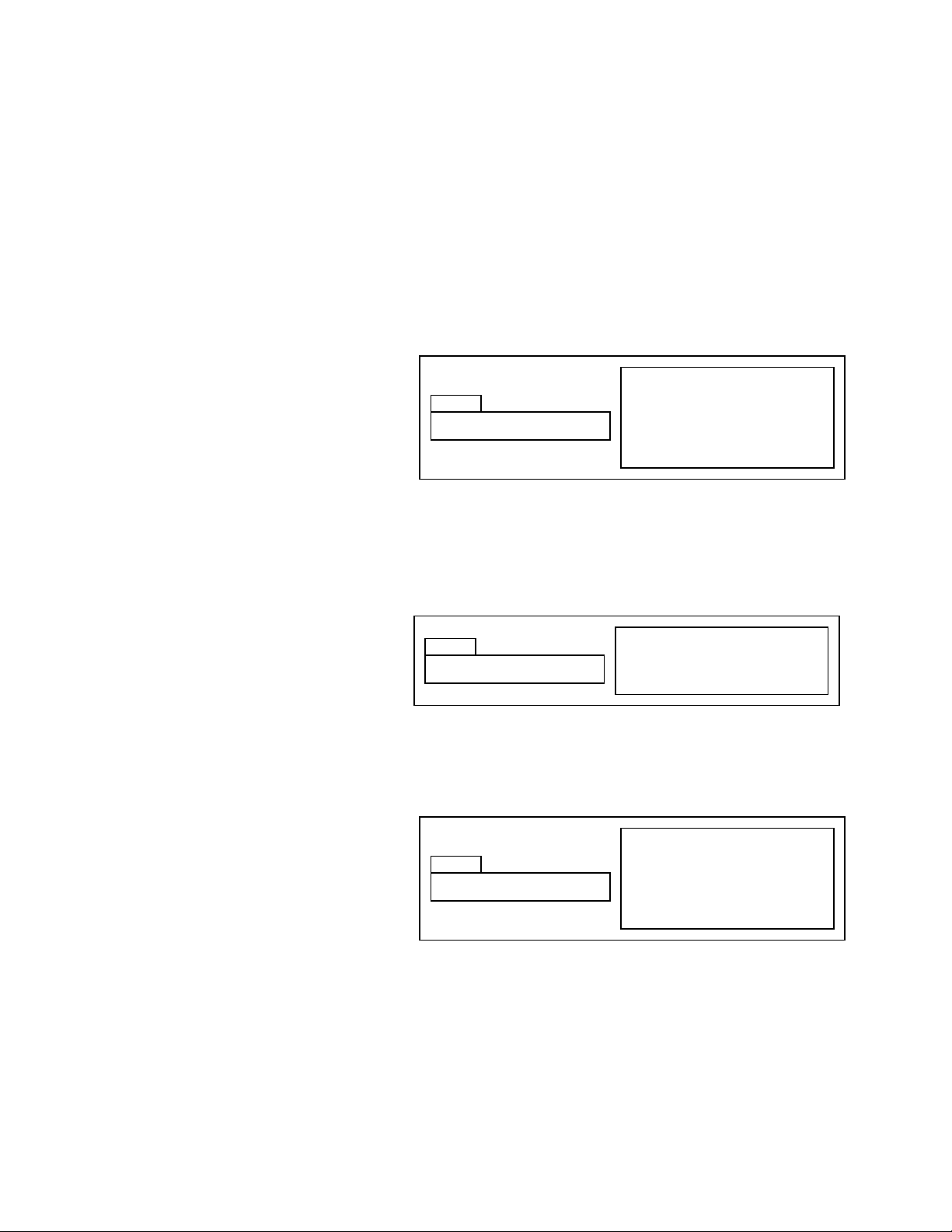
COMPRESS: XX
C
Hold DISPLAY & press ΔMENU key
from main display, press ΔMENU
key
Use UP and DOWN keys to set
Press DISPLAY key to return to
main display
REFILL: FULL OUT
R
Hold DISPLAY & press ΔMENU key
from main display, press ΔMENU
key
Use UP and DOWN keys to set
Press DISPLAY key to return to
main display
Hold DISPLAY & press ΔMENU key
from main display
Press RUN to send piston to home
(forward) position
GO HOME: HIT RUN
HP
the ΔMENU key twice. Use the UP or DOWN arrow key to increase or decrease the low pressure limit. To return
to the main screen, press the DISPLAY key.
When the low pressure limit is violated, the pump stops running, the lower red LED lights and the display shows
LO PRESS XXXX.
Configuration Screens
To access the configuration screens, hold the DISPLAY key while pressing the ΔMENU key. To cycle to the next
command, press the ΔMENU key.
Setting the Compressibility Compensation Factor
Various fluids have different
compressibilities at different pressures.
You can adjust for compressibility by
setting the compressibility compensation
factor. The default setting is 0. The
maximum setting is 60. Each increment
increases motor speed by approximately
1%.
To change the compressibility compensation factor, hold the DISPLAY key and press the ΔMENU key (from the
main display), or, when in the configuration screens press the ΔMENU key to display the “compress” screen. Use
the UP or DOWN arrow key to increase or decrease the compressibility compensation factor. To return to the
main screen, press the DISPLAY key.
Sending the Piston to the Home Position
The piston can be sent to the fully forward
position, useful when changing piston
seals.
To send the piston to the forward position,
hold the DISPLAY key and press the
ΔMENU key (from the main display). Press the RUN key. The motor will drive the piston to the home position.
To return to the main screen, press the DISPLAY key.
Changing the Refill Rate Setup
Optos pumps can be set to a variety of refill:output ratios. The default setting, refill: full out, optimizes the ratio
for minimal pulsation throughout the flow
rate range, by minimizing the refill portion
of the duty cycle. Other settings are:
refill: 15 out: 85 (sets the ratio to 15:85),
refill: 30 out: 70 (sets the ratio to 30:70),
refill: 50 out: 50 (sets the ratio to 50:50),
refill: 70 out: 30 (sets to ratio to 70:30).
To change the refill rate, hold the DISPLAY key and press the ΔMENU key (from the main display), or, when in the
configuration screens press the ΔMENU key to display the “refill” screen. Use the UP or DOWN arrow key to
change the refill:output ratio. To return to the main screen, press the DISPLAY key.
Setting the Liquid End Type (Piston size and Liquid End material)
Optos pumps can have one of several different liquid ends and pistons installed. When shipped from the factory,
the setting is for the model purchased.
13
Page 20
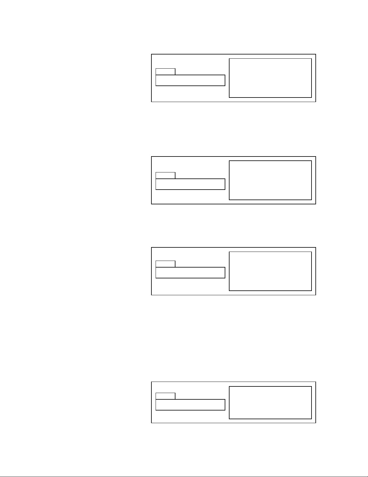
HEAD: 1/8 SS
LE
Hold DISPLAY & press ΔMENU key
from main display, press ΔMENU
key twice times
Use UP and DOWN keys to set
Press DISPLAY key to return to
main display
REMOTE: OFF
REM
Hold DISPLAY & press ΔMENU key
from main display, press ΔMENU
key three times
Use UP and DOWN keys to set
Press DISPLAY key to return to
main display
VERSION: X.XX
V
Hold DISPLAY & press ΔMENU key
from main display, press ΔMENU
key four times
Use UP and DOWN keys to set
Press DISPLAY key to return to
main display
HOME OFFSET: XX
HO
Hold ΔMENU & press DISPLAY key
from main display
Use UP and DOWN keys to set
Press DISPLAY key to return to
main display
You may have occasion to wish to change the piston and/or liquid end type to change the flow rate range or
material of construction.
To change the liquid end type, hold the
DISPLAY key and press the ΔMENU key
(from the main display), or, when in the
configuration screens press the ΔMENU
key to display the “head” screen. Use the
UP or DOWN arrow key to change the
liquid end type. The numeric field
indicates piston size (3/32, 1/8, ¼), and
alpha field indicates material of construction of the head (SS, PK). To return to the main screen, press the
DISPLAY key. The high and low pressure limits are reset when changing the liquid end type to the default for that
type.
Setting the Remote Control Setting
Optos pumps can be controlled remotely
via an analog signal (either 4-20 mA or 05 VDC). If you wish to operate the Optos
pump remotely using one of the available
analog signals, you need to set the field to
that signal (operating via RS232 does not
require any setup).
To change the remote control setting, hold the DISPLAY key and press the ΔMENU key (from the main display),
or, when in the configuration screens press the ΔMENU key to display the “remote” screen. Use the UP or DOWN
arrow key to change the remote control setting. To return to the main screen, press the DISPLAY key.
Viewing the EPROM Revision Level
Optos pumps have EPROM software.
You can view the version of software
installed.
To view the software version, hold the
DISPLAY key and press the ΔMENU key
(from the main display), or, when in the
configuration screens press the ΔMENU
key to display the “version” screen. To
return to the main screen, press the DISPLAY key.
Advanced Screens
To access the configuration screens, hold the ΔMENU key while pressing the DISPLAY key. To cycle to the next
command, press the ΔMENU key.
Setting the Home Position Offset
The software for speeding up and slowing
down the motor is set off the home
position sensor location. The software is
optimized for running flows with minimal
pulse at substantial pressures. If your
conditions are different, you may wish to
change the home offset setting to
minimize pulsation. The default setting is 0. Other settings are from -99 to +99.
14
Page 21
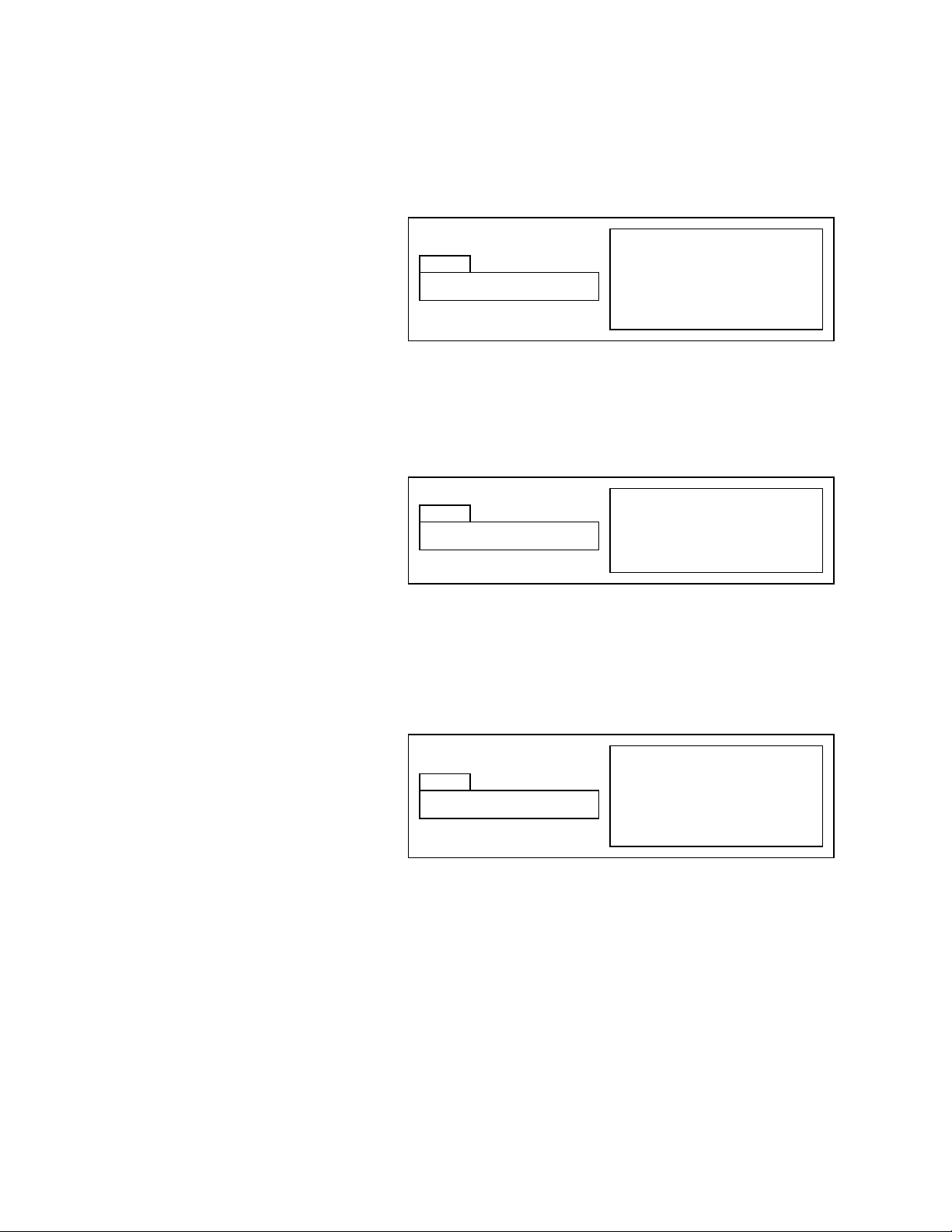
PRESS LIMIT: ENA
LI
Hold ΔMENU & press DISPLAY key
from main display, press ΔMENU
Use UP and DOWN keys to set
Press DISPLAY key to return to
main display
STOP STALL: ON
SS
Hold ΔMENU & press DISPLAY key
from main display, press ΔMENU
Use UP and DOWN keys to set
Press DISPLAY key to return to
main display
0-5V OUT: PRESS
S
Hold ΔMENU & press DISPLAY key
from main display, press ΔMENU
Use UP and DOWN keys to set
Press DISPLAY key to return to
main display
To change the home position offset setting, hold the ΔMENU key and press the DISPLAY key (from the main
display), or, when in the advanced screens press the ΔMENU key to display the “home offset” screen. Use the UP
or DOWN arrow key to change the home offset setting. To return to the main screen, press the DISPLAY key.
Setting the Output Function
One of the outputs on the I/O ports is a 05V output. This output can be changed
between pressure and flow.
To change the output, hold the ΔMENU
key and press the DISPLAY key (from the
main display), or, when in the advanced
screens press the ΔMENU key to display
the “output” screen. Use the UP or DOWN arrow key to change the setting (PRESS means the output will
correspond to pressure, FLOW means the output will correspond to flow). To return to the main screen, press
the DISPLAY key.
Setting the High/Low Pressure Limit Shutdown
Optos pumps (with the optional damper)
can have their high and low pressure
limits de-activated. The default setting is
ENA (limits are active).
To change the limit setting, hold the
ΔMENU key and press the DISPLAY key
(from the main display), or, when in the
advanced screens press the ΔMENU key to display the “limit” screen. Use the UP or DOWN arrow key to change
the limit setting (DIS = limits de-activated; ENA = limits activated). To return to the main screen, press the
DISPLAY key.
Setting the Motor Stall Shutdown
If Optos pumps are not fitted with the
optional damper or if the pressures limits
are de-activated, the motor will stall
when exposed to excessive pressure.
When the stall stop field is set to ON, the
pump will stop pumping when a stall
condition is noted; when the stall stop
field is set to OFF, the pump will
continue pumping, or trying to pump even in the presence of a motor stall. The default setting is OFF.
To change the stall setting, hold the ΔMENU key and press the DISPLAY key (from the main display), or, when in
the advanced screens press the ΔMENU key to display the “stall” screen. Use the UP or DOWN arrow key to
change the limit setting (OFF = pump runs after stall; ON = pump stops after stall). To return to the main screen,
press the DISPLAY key.
15
Page 22
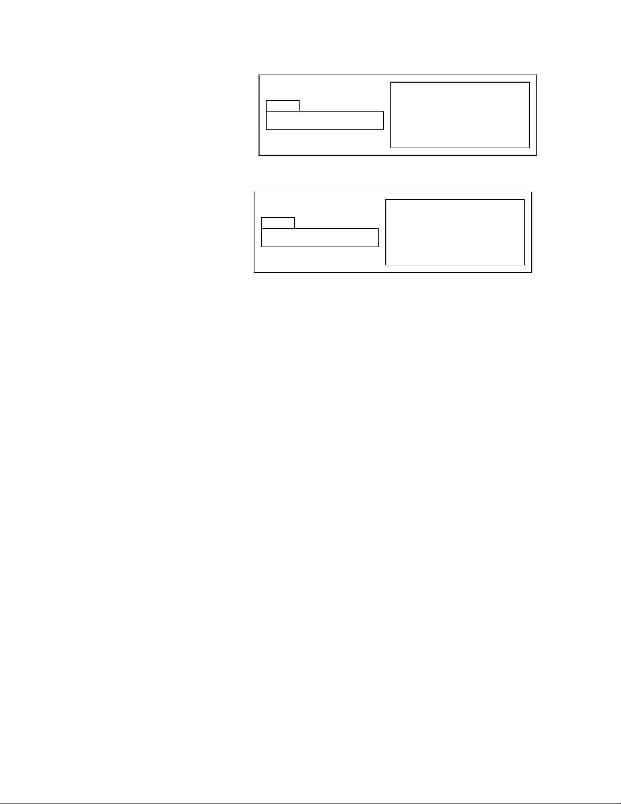
PRESS 0: HIT RUN
XDC
Hold ΔMENU & press DISPLAY key
from main display, press ΔMENU
Press RUN key to zero
Press DISPLAY key to return to
main display
STROKE: .125
ST
Hold ΔMENU & press DISPLAY key
from main display, press ΔMENU
Press DISPLAY key to return to
main display
Viewing the Stroke Length
You may view the stroke length of the
piston of your pump by holding the ΔMENU
key and pressing the DISPLAY key (from
the main display), or, when in the
advanced screens press the ΔMENU key to
display the “stroke” screen. To return to
the main screen, press the DISPLAY key.
Zeroing the Pressure Transducer
If the Optos pump is fitted with the
“Plus” option, a pressure transducer is
present in the damper assembly. The
pressure transducer is sensitive to
temperature changes and can read a
pressure when no pressure is present. It is
possible to re-zero the pressure
transducer.
To zero the pressure transducer, hold the ΔMENU key and press the DISPLAY key (from the main display), or,
when in the advanced screens press the ΔMENU key to display the „press” screen. Press the RUN key to zero the
transducer. Be sure to do this when there is no pressure on the pump. To return to the main screen, press the
DISPLAY key.
16
Page 23

CAUTION: It is important to note that salts and buffers can lead to corrosion of stainless steel or distortion
of plastics if they are left in contact with the pump for long periods of time. Failure to flush potentially
corrosive substances from the pump may void your warranty.
Pump Limits
You should note the limits of your Optos pump. Exceeding or violating these limits may damage your pump and
will void your warranty.
Viscosity Limits
Liquids with viscosities of 100 centipoise or higher often reduce nominal flow rate values. You cannot pump
liquids with viscosities exceeding 500 centipoise.
Chemical Limits
Some buffers, particularly halide salts at high concentrations, can cause corrosion of type 316 stainless steel. If
you leave buffers in the pump, crystallization may occur and cause damage to the seal material. Some solvents
can swell the plastic material in the valves or the piston seal. Usually, you can substitute less damaging fluids,
and you can minimize potential damage by carefully flushing the pump. You can sometimes substitute special
materials; please consult with the factory.
Mechanical Limits
Pumped fluids should be free of particulate matter, since clogged valves may result in erratic flow rates. We
strongly recommend the use of a filter on the inlet line to protect the valves from small particles. A 10 micron
sintered stainless steel filter is available from Eldex (Part No. 5776) and is suitable for most applications. When
you need to avoid metal, a 10 micron plastic filter is available from Eldex (Part No. 1279).
Damage to the mechanical parts will result from subjecting the pump to excessive pressure. Do not try to pump
fluid against pressures which exceed the maximum pressure capability of your model.
Temperature Limits
Eldex pumps are designed to operate under ambient temperature conditions. If you take appropriate precautions
to prevent condensation, you can use the pump in a cold room. Do not use the pump in an environment which
exceeds 35ºC.
It is possible to pump fluids which are at elevated temperatures. Although the reaction of specific fluids at
elevated temperatures to the wetted parts may vary, it is usually the plastic materials in the liquid end which will
be of concern. Generally, the CTFE maintains integrity at temperatures up to 200ºC. The PTFE piston seal
material is generally good to 260ºC. You will want to consult the factory when pumping fluids at elevated
temperatures if there is any question in your mind about how the wetted parts will react.
Shutdown Procedures
Eldex pumps are manufactured using materials selected to resist corrosion. However, some buffers, most
notably halide salts at high concentration, are capable of corroding type 316 stainless steel, and some solvents
are capable of distorting CTFE or other plastics used in the pumps. Therefore, it is important to flush the pump
after using any potentially damaging materials.
To flush the pump, first pump distilled water to remove any salt(s) or solids. You should do this for a minimum
of ten minutes as soon as possible after using the pump. Next, you should flush the pump with an inert solvent
such as methanol for at least five minutes.
17
Page 24
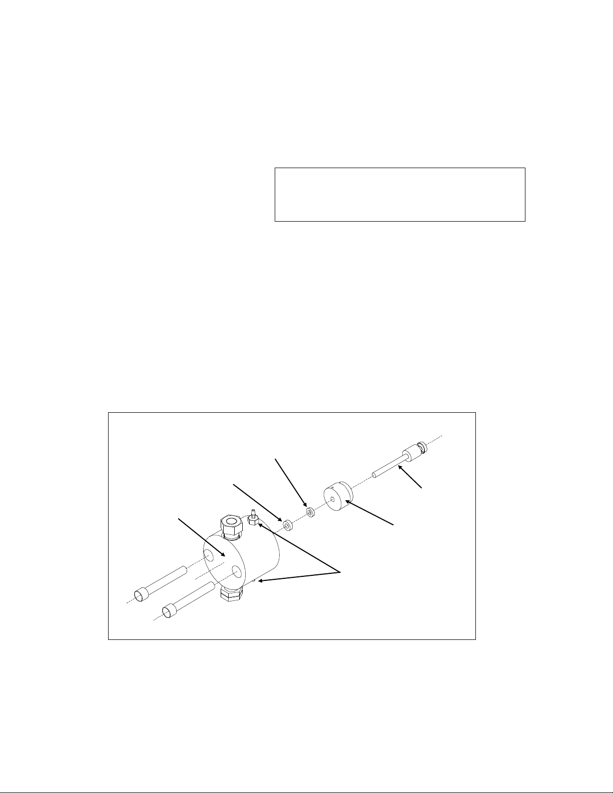
Figure 4.1: Pump Assembly
TIP: We have found, especially with metal-free seals, that
“breaking-in” the seals with IPS or methanol for an hour
or so, under conditions similar to your expected operating
conditions enhances seal life.
Liquid End
Wash Ports
Piston Seal
Backup Washer
Retainer/Wash
Piston
MAINTENANCE
We have designed Eldex Metering Pumps to give years of trouble-free service. By following a few simple
maintenance procedures, you can ensure the longevity of your pump.
Cleaning
Before cleaning your pump, disconnect the pump from the power supply. Cleaning can be accomplished by
wiping down with a damp cloth.
Piston Seal
The seal material used is a specially formulated
PTFE. It is the standard seal material because
of its broad range of chemical compatibility, its
mechanical properties, and its stability in
reciprocating applications.
The length of service to be expected from any given piston seal depends on a wide variety of factors, including
the fluid being pumped and the pressure of the system. It is critically important that the seal be replaced
immediately upon failure, or better yet, before failure, because fluid can travel into the mechanical housing of
the pump and cause corrosion damage.
When a leak occurs, you may notice fluid just underneath the liquid end. However, a leak may not always be
visible, particularly at low flow rates. We suggest you place a wick or litmus paper up the drain slots just
underneath the liquid end. You should remove the wick or litmus paper periodically and check for wetness or
color changes to see if leakage has occurred.
Piston seal life can often be significantly extended by using the piston wash system integrated in the pump.
Replacing the Piston Seal
1. Use tools supplied with Part Nos, 5911, (3/32” installation tool and 5/32 hex key); 5941(installation tool
and 5/32 hex key); 5944, (1/4” diameter dowel pin and 5/32 hex key).
2. Send the piston to the home position. Turn the power switch to OFF.
3. Remove the liquid end from the pump as follows: Unscrew the two 5/32” socket head bolts. Pull the
liquid end straight out from the pump housing, in line with the axis of the piston. If you cock or tilt the
liquid end, you may break the piston. See Figure 4.1.
18
Page 25
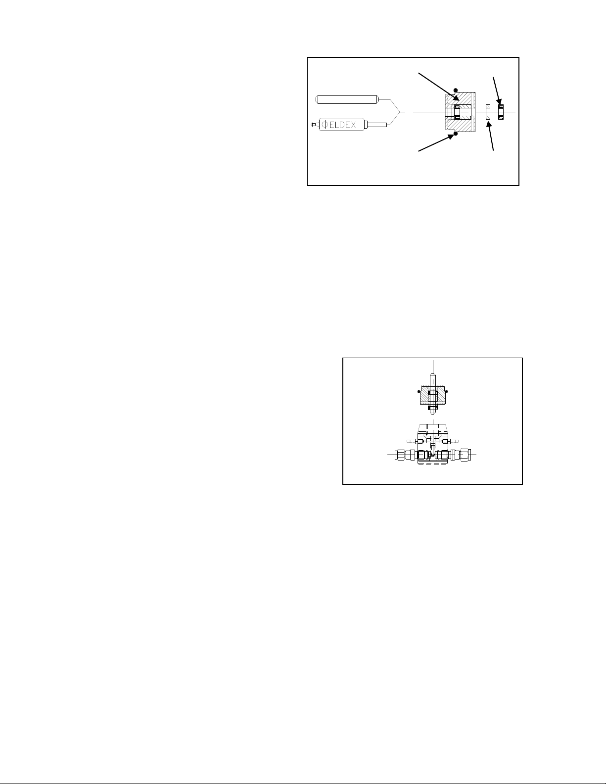
Figure 4.1: Piston Seal Assembly
Figure 4.2: Piston Seal Replacement
Retainer/Wash
O Ring
Backup
Washer
Piston Seal
4. Remove the retainer/wash from the liquid
end, and insert the installation tool/dowel
pin into the liquid end through the piston
seal (if your pump uses a 3/32” or 1/8”
diameter piston, the installation tool has a
“hooked” end, which is used to remove the
seals). If you are using the installation tool,
hook the existing seals and remove and
discard both the washer and the seal. If you
are using the ¼” dowel pin, rock the dowel
pin back and forth gently, and remove and
discard both the washer and seal. Do not
scratch the walls of the piston seal gland in the liquid cylinder with the tool/dowel pin.
5. Inspect the piston. You can remove the piston by moving the piston up in the slot which holds it in
place. If the piston has scratches on the sapphire, or significant corrosion on the stainless steel piston
holder, you should replace it. If there is minor corrosion on the piston holder, clean the piston holder.
Also inspect for evidence of deposits on the sapphire. If deposits are present on the sapphire
(discoloration or particulates), clean it. If the sapphire does not clean, you should replace the piston.
6. Inspect the retainer. Clean the retainer/wash if necessary. If there is evidence of wear, or if the piston
does not fit snugly in the retainer/wash, or if the retainer/wash grips the piston too tightly, you should
replace the retainer/wash.
7. Inspect the liquid cylinder, paying special attention to the gland for the piston seal. Any scratches or
irregularities will require replacement of the liquid end.
8. Clean all parts with a liquid detergent, followed by a rinse. Clean any fluid in the mechanical end of the
pump.
9. Insert the installation tool/dowel pin into the
retainer/wash and then into the new seal backup
washer (if present) and new piston seal. When
inserting the tool through the new piston seal, the
piston seal should lay flat on a hard surface with the
spring side down (the seal will generally “snap” onto
the tool). Position the parts on the tool in the order
shown. Insert the tool into the liquid end bore.
CAUTION: The open side of the seal (side
revealing the spring or the O ring) should face the
closed (fluid side) end of the liquid end.
10. Keeping the tool perpendicular with the face of the liquid end, push the piston seal and washer into the
liquid end bore, by pressing down gently and evenly on the edge of the retainer/wash with both thumbs.
11. Withdraw the tool, while holding the retainer/wash and liquid end firmly in place. When installing the
retainer/wash, make sure you line up the holes in the retainer with the wash system.
12. Reinstall the liquid end on the pump. See Figure 4.1.
PRECAUTIONS:
1. Do not re-use the old piston seal.
2. Cleanliness is very important for optimal seal and check valve operation.
3. Note suggestion regarding seal “break-in” on page 15.
NOTE: If you retain the tools supplied with Eldex Part Nos. 5911, 5941, or 5944, you can purchase just the
seals and re-use the tools.
19
Page 26
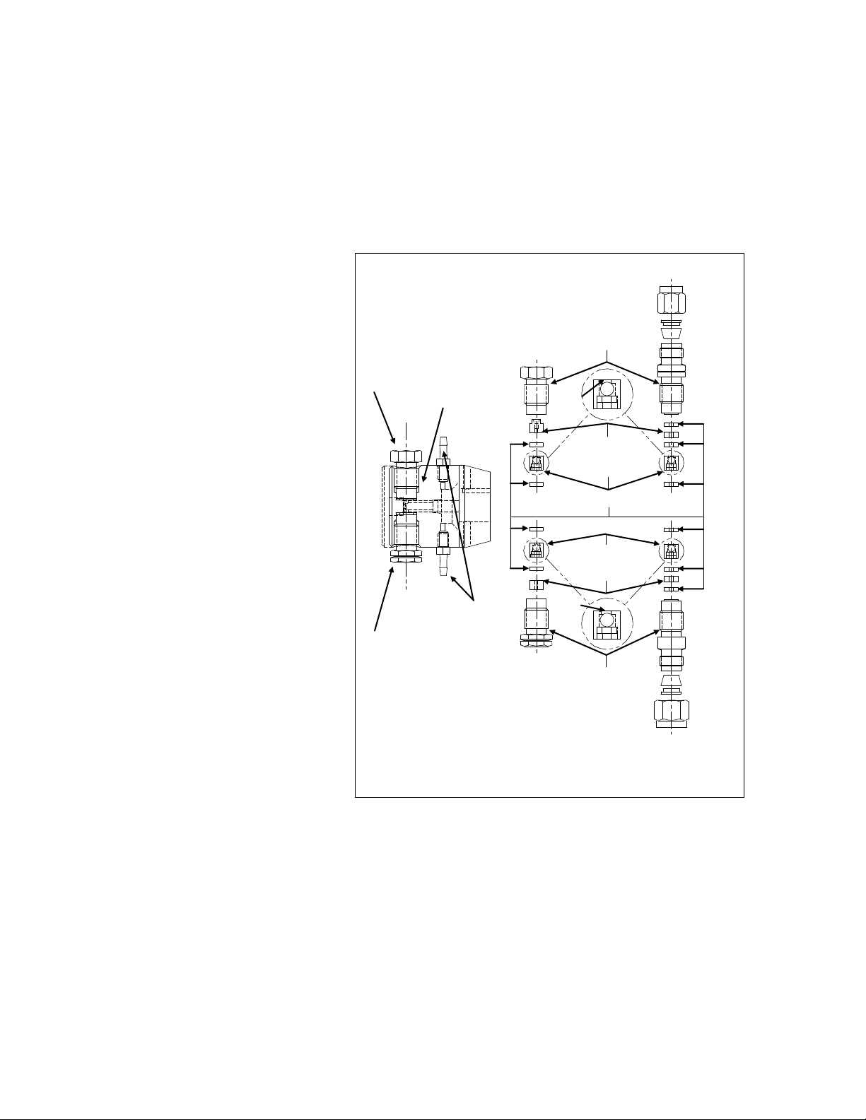
Figure 4.4: Liquid End Assembly
Note Orientation of Inlet and Outlet
Valve Cartridges
Outlet Valve Housing
Outlet Valve Insert
Outlet Valve Cartridge
Valve Seal
Inlet Valve Cartridge
Inlet Valve Insert
Inlet Valve Housing
Inlet Valve
Cylinder
Outlet Valve
Wash Ports
Triangular
opening
Triangular
opening
Replacing Valves
Always replace valves in a clean area to prevent dust and dirt from entering the pump.
Removal of Existing Valves
The valves are the two hexagon-shaped components on the liquid end assembly (see Figure 4.4). Inlet valves
can be distinguished from outlet valves by the groove on the hexagonal part of the valve. Remove the valves
with a ½” wrench, turning in a counter-clockwise direction. After removal, be careful to keep the valve oriented
so the translucent washers face upwards to prevent parts from falling out. If you wish to replace the cartridge in
the valve, you may purchase replacement
cartridges, which include the cartridge
and instructions.
Installation of New Valves
1. Inlet valves can be distinguished
from outlet valves by the groove
on the hexagonal part of the
valve.
2. Unscrew the shipping nut and
remove the metal shipping
washer, as these are not used for
installation of the valves.
3. Insert the new valve into the
liquid end assembly and tighten
by hand until just finger-tight.
Then use a ½” wrench and
tighten ¼ turn more. You should
tighten valves to the point at
which no further leakage occurs,
or not more than 4.5 ft./lbs.
OVERTIGHTENING THE VALVES
CAN CAUSE THE SAPPHIRE SEATS
TO CRACK.
STABILIZE THE VALVE WITH A ½”
WRENCH WHEN ATTACHING YOUR
FITTINGS TO PREVENT FURTHER
VALVE TIGHTENING. DO NOT
TIGHTEN FITTINGS TO BEYOND 40
IN./LBS., OR THE POINT WHERE NO
FURTHER LEAKAGE OCCURS.
Replacing Valve Cartridges
1. Remove the valve from the cylinder (see above for detailed instructions).
2. Using the smaller dowel pin provided (1-1/4” long by 1/8”diameter), press out the internal components
of the valve assembly using a steady pressure. Do not hammer parts through with the dowel pin or
hammer on the dowel pin. Do not allow the valve parts to fall out of the valve onto a hard surface.
3. Reassemble the valve by placing the valve insert in the valve housing using the larger (3/16”) dowel pin
provided (1373 and 1374 valves use a total of 3 washers, one is installed before installing the valve
insert). Make sure it is oriented correctly (see Figure 4.4). Press a CTFE seal into place. Slide the
valve cartridge into the valve housing making certain it is oriented correctly. Press another new CTFE
seal into place. The CTFE seal will extend approximately 0.020 – 0.030” from the valve housing.
4. Re-install the rebuilt valve into the liquid end assembly and tighten by hand until just finger-tight. Then
use a ½” wrench and tighten ¼ turn more. You should tighten valves to the point at which no further
leakage occurs, or not more than 4.5 ft./lbs.
20
Page 27

Question
Answer
Solution
Is the motor turning?
No
Check electrical connections:
1. Is instrument plugged in?
2. Does outlet provide electricity?
3. Is fuse blown? If so, replace.
Is fluid degassed prior to use?
No
Degass fluid prior to use:
1. Boil.
2. Bubble helium through fluid.
3. Subject fluid to a vacuum.
Is fluid filtered?
No
1. Do not pump fluids with suspended particles (a
particle as small as ten microns can clog a valve).
2. Install an inlet line filter.
3. Flush with liquid detergent or 20% solution of nitric
acid (at max. flow for about 10 minutes), or suck
cleaning fluid through pump with a syringe.
4. Ultrasonicate valve assembly.
Is filter clogged?
Yes
Clean filter (clogged filter can create restriction to flow,
causing cavitation).
Is mechanical assembly OK?
No
Inspect parts of mechanical assembly; is piston broken?,
pushrod frozen in bushing?
Are valves OK?
No
Rebuild or replace valves (excessive force used to tighten
fittings to valves or valves to cylinder can cause sapphire
seats to crack, chip, or shatter, thereby inhibiting flow).
Question
Answer
Solution
What is backpressure on pump
Less
than 25
psi
Insufficient backpressure, create more pressure on pump so
valves can work properly (install backpressure regulator, or
length of small I.D. tubing).
Is fluid degassed prior to use?
No
Degass as per above.
Is fluid filtered?
No
Clean valves as per above, install inlet line filter.
Is filter clogged?
Yes
Clean filter.
Is there a leak at fitting(s)
Yes
Tighten fittings.
Is there a leak at valve
connection?
Yes
Tighten valves
Are valves OK?
No
Rebuild or replace valves.
Question
Answer
Solution
Are seals worn?
Yes
Replace piston seal.
Question
Answer
Solution
Is fluid degassed prior to use?
No
Degas as per above.
Troubleshooting
Symptom: No flow (probably cause(s) shown in bold)
Symptom: Erratic flow (probable cause(s) shown in bold)
Symptom: Leakage
Symptom: Steadily decreasing flow rate
21
Page 28

Order
No.
Description
Preventive Maintenance Kits
5918
Includes two PTFE piston seals, tools for installation, two valve cartridges, one retainer/wash, a sintered stainless
steel filter.
Piston Seals
5911
Piston seal assembly kit; includes one PTFE seal, and tools for installation.
5912
Piston seal replacement kit; includes two PTFE seals.
5913
Piston seal replacement kit; includes five PTFE seals.
Valves
1369
Inlet valve assembly, cartridge style, 1/4"-28 fitting.
1372
Outlet valve assembly, cartridge style, 10-32 fitting.
1373
Inlet valve assembly, cartridge style, 1/8" Swagelok® fitting.
1374
Outlet valve assembly, cartridge style, 1/8" Swagelok® fitting.
1371
Inlet valve assembly, cartridge style, 10-32 fitting.
1370
Outlet valve assembly, cartridge style, 1/4"-28 fitting.
1381
Valve cartridge kit (rebuilds one inlet or one outlet valve).
Piston
5819
1/8" sapphire piston.
Liquid End Assembly
5902
Includes inlet and outlet valve assemblies, cylinder, piston seals and retainer. Piston not included.
Fittings
5988
Includes 60 cm of 1/8" Teflon inlet tubing, inlet (1/4-28) and outlet (10-32) tube nuts, and outlet ferrule.
Filters
5776
10 micron sintered stainless steel filter, with 60 cm long Teflon inlet tube and tube nut.
Other Parts
5899
Retainer/wash assembly.
For other parts, consult factory.
Optos SPARE PARTS AND ACCESSORIES
For 3/32” Stainless Steel Pump
22
Page 29

Order No.
Description
Preventive Maintenance Kits
5920
Includes two PTFE piston seals, tools for installation, two valve cartridges, one retainer/wash, a sintered stainless
steel filter.
Piston Seals
5941
Piston seal assembly kit; includes one PTFE seal, and tools for installation.
5942
Piston seal replacement kit; includes two PTFE seals.
5943
Piston seal replacement kit; includes five PTFE seals.
Valves
1369
Inlet valve assembly, cartridge style, 1/4"-28 fitting.
1372
Outlet valve assembly, cartridge style, 10-32 fitting.
1373
Inlet valve assembly, cartridge style, 1/8" Swagelok fitting.
1374
Outlet valve assembly, cartridge style, 1/8" Swagelok fitting.
1371
Inlet valve assembly, cartridge style, 10-32 fitting.
1370
Outlet valve assembly, cartridge style, 1/4"-28 fitting.
1381
Valve cartridge kit (rebuilds one inlet or one outlet valve).
Piston
5820
1/8" sapphire piston.
Liquid End Assembly
5903
Includes inlet and outlet valve assemblies, cylinder, piston seals and retainer. Piston not included.
Fittings
5988
Includes 60 cm of 1/8" Teflon inlet tubing, inlet (1/4-28) and outlet (10-32) tube nuts, and outlet ferrule.
Filters
5776
10 micron sintered stainless steel filter, with 60 cm long Teflon inlet tube and tube nut.
Other Parts
5900
Retainer/wash assembly.
For other parts, consult factory.
For 1/8” Stainless Steel Pump
23
Page 30

Order No.
Description
Preventive Maintenance Kits
5922
Includes two PTFE piston seals, tools for installation, two valve cartridges, one retainer, a sintered stainless steel
filter.
Piston Seals
5944
Piston seal assembly kit; includes PTFE seal, and tools for installation.
5945
Piston seal replacement kit; includes two PTFE seals, no tools..
5946
Piston seal replacement kit; includes five PTFE seals, no tools..
Valves
1373
Inlet valve assembly, cartridge style, 1/8" Swagelok fitting.
1374
Outlet valve assembly, cartridge style, 1/8" Swagelok fitting.
1381
Valve cartridge kit (rebuilds one inlet or one outlet valve).
Pistons
5821
1/4" sapphire piston.
Liquid End Assembly
5904
Includes inlet and outlet valve assemblies, cylinder, piston seals and retainer. Piston not included.
Other Parts
5901
Retainer/wash assembly.
For other parts, consult factory.
For 1/4” Stainless Steel Pump
24
Page 31

Order No.
Description
Preventive Maintenance Kits
5923
Includes two uhmw polyethylene seals, backup washers, tools for installation, two valve cartridges, one retainer, a
sintered stainless steel filter.
Piston Seals
5914
Piston seal assembly kit; includes one uhmw polyethylene seal, backup washer, and tools for installation.
5915
Piston seal replacement kit; includes two uhmw polyethylene seals, backup washers.
5916
Piston seal replacement kit; includes five uhmw polyethylene seals, backup washers.
Valves
1377
Inlet valve assembly, cartridge style.
1378
Outlet valve assembly, cartridge style.
1383
Valve cartridge kit (rebuilds one inlet or one outlet valve).
Pistons
5819
1/8" sapphire piston.
Liquid End Assembly
5905
Includes inlet and outlet valve assemblies, cylinder, piston seals and retainer. Piston not included.
Fittings
5987
Includes 60 cm of 1/8" Teflon inlet tubing, inlet (1/4-28) and outlet (1/4-28) tube nuts.
Filters
1279
10 micron plastic filter, with 60 cm long Teflon inlet tube and tube nut.
Other Parts
5896
Retainer assembly.
For other parts, consult factory.
For 3/32” PEEK Pumps
25
Page 32

Order No.
Description
Preventive Maintenance Kits
5924
Includes two uhmw polyethylene seals, backup washers, tools for installation, two valve cartridges, one retainer, a
10 micron plastic filter.
Piston Seals
6007
Piston seal assembly kit; includes one uhmw polyethylene metal-free seal, backup washer, and tools for installation.
6008
Piston seal replacement kit; includes two uhmw polyethylene metal-free seals, backup washers.
6009
Piston seal replacement kit; includes five uhmw polyethylene metal-free seals, backup washers.
Valves
1377
Inlet valve assembly, cartridge style.
1378
Outlet valve assembly, cartridge style.
1383
Valve cartridge kit (rebuilds one inlet or one outlet valve).
Pistons
5820
1/8" sapphire piston.
Liquid End Assembly
5906
Includes inlet and outlet valve assemblies, cylinder, piston seals and retainer. Piston not included.
Fittings
5987
Includes 60 cm of 1/8" Teflon inlet tubing, inlet (1/4-28) and outlet (1/4-28) tube nuts, and outlet ferrule.
Filter
1279
10 micron plastic filter, with 60 cm long Teflon inlet tube and tube nut.
Other Parts
5897
Retainer assembly.
For other parts, consult factory.
For 1/8” PEEK Pumps
26
Page 33

Order No.
Description
Preventive Maintenance Kits
5925
Includes two uhmw polyethylene seals, backup washers, tools for installation, two valve cartridges, one retainer, a
10 micron plastic filter.
Piston Seals
6010
Piston seal assembly kit; includes one uhmw polyethylene metal-free seal, and tools for installation.
6011
Piston seal replacement kit; includes two uhmw polyethylene metal-free seals.
6012
Piston seal replacement kit; includes five uhmw polyethylene metal-free seals.
Valves
1377
Inlet valve assembly, cartridge style.
1378
Outlet valve assembly, cartridge style.
1383
Valve cartridge kit (rebuilds one inlet or one outlet valve).
Pistons
5821
1/8" sapphire piston.
Liquid End Assembly
5907
Includes inlet and outlet valve assemblies, cylinder, piston seals and retainer. Piston not included.
Fittings
5987
Includes 60 cm of 1/8" Teflon inlet tubing, inlet (1/4-28) and outlet (1/4-28) tube nuts, and outlet ferrule.
Filter
1279
10 micron plastic filter, with 60 cm long Teflon inlet tube and tube nut.
Other Parts
5898
Retainer assembly.
For other parts, consult factory.
For ¼” PEEK Pumps
27
Page 34

RJ 11 Pin
Function
DB 9 pin
1,6 (white, purple)
Ground
5
2 (black)
DSR (Input)
6
3 (red)
RXD (Input to pump)
2
4 (green)
TXD (Output from pump)
3
5 (yellow)
DTR (Output)
4
Command
Response
Default
Minimum
Maximum
Comments
RU
OK/ Sets the pump to the RUN state.
ST
OK/ Sets the pump to the STOP state.
SFxx.xxx
OK/
1.0
Pump specific
Pump specific
Sets the flow rate to xx.xxx mL/min
RF
Okxxxxx/
1.0
Pump specific
Pump specific
Reads the flow rate
ID
Okxyzaaa/
Reads ID of pump where:
x = piston diameter (0=.093, 1=.125, 2=.250)
y = piston stroke (0=.125, 1=.250, 2=.500)
z = pump material (0=ss, 1=pk)
Aaa = EPROM revision
RP
OK,xxxx/
0 Pump specific
Reads the pump pressure
SHxxxx
OK/
Pump
specific
0
Pump specific
Sets the pump high pressure limit
SLxxxx
OK/ 0 0
Pump specific
Sets the pump low pressure limit
RH
Okxxxx/
Pump
specific
0
Pump specific
Reads the pump high pressure limit
RL
Okxxxx/
0 0 Pump specific
Reads the pump low pressure limit
SC,xxxx
OK/ 0 0
60
Sets the pump compressibility compensation
RC
OK,xxxx/
0 0 60
Reads the pump compressibility compensation
SRxx
OK/ Sets the pump refill rate factor
RR
Okxx/
Reads the pump refill rate factor
KD
OK/ Disables keypad (default status at power-up is
enabled).
KE
OK/ Enables keypad.
SDx
OK/ 1 0 2 Sets the pump piston diameter (0=.093, 1=.125,
2=.250)
RD
Okx/ 1 0 2 Reads the pump piston diameter (0=.093, 1=.125,
2=.250)
SSx
OK/ 1 0 2 Sets the pump stroke (0=.125, 1=.250, 2=.500)
RS
Okx/ 1 0 2 Reads the pump stroke (0=.125, 1=.250, 2=.500)
SMx
OK/ 0 0 1 Sets the pump material (0=ss, 1=pk)
RM
Okx/ 0 0 1 Reads the pump material (0=ss, 1=pk)
RX
Okxyz/
Reads the pump fault status where:
X = motor stall, 0=no fault, 1=fault
Y = hi press limit, 0=no fault, 1=fault
Z = lo press limit, 0=no fault, 1=fault
SX
OK/ Sets LED to red and stops pump
APPENDIX
RS232
An RS232C modular jack (connector is RJ-11) is on the rear panel. It is configured for 9600 baud, 8 data
bits, 1 stop bit, and no parity. Pinout is:
The pump uses hardware handshaking. The pump does not transmit on the TXD output if the DSR input is
at a low logic level. The pump does not receive on the RXD input when the DTR output is at a low logic
level. A low logic level is –3.0 to –15 volts, and a high logic level is 3.0 to 15 volts.
The pump does not send a message except when queried. Each command is characterized by a unique twoletter command code. Only one command can be issued per line. Case is irrelevant. Command strings sent
by the pump are terminated by the “/” character.
28
Page 35

RI
Okxxxxxyyyy
zzzzaaaabbbb
ccdefgh/
Xxxxx=pump flow rate
Yyyy=pressure
Zzzz=high pressure limit
Aaaa=low pressure limit
Bbbb=compressibility compensation
Cc=refill rate factor
D=piston diameter (0=.093, 1=.125, 2=.250)
E=piston stroke (0=.125, 1=.250, 2=.500)
F=pump material (0=ss, 1=pk)
G=keyboard status (0=enabled, 1=disabled)
H=fault (0=none, 1=motor, 2=high pressure, 3=low
pressure)
Z
OK/ Reset Command buffer
Warranty
Eldex products are guaranteed against manufacturing defects for one year from the date of shipment. Parts and
labor are both covered under the warranty. Seals, valves, and other disposable items are not included in the
warranty. The warranty does not apply when there has been obvious misuse or mistreatment by the user or when
damage has been caused by attempted repairs by the user. Exposure of Eldex products to inappropriate
chemicals also voids the warranty.
Eldex Laboratories, Inc. will not assume responsibility for contingent liability through alleged failure(s) of its
products.
There are no warranties, express or implied, which extend beyond this description. Eldex neither assumes, nor
authorizes any person to assume for it, any other liability in connection with the sale and use of the products.
Damages are limited strictly to repair or replacement of the products. Eldex expressly disclaims liability for
incidental and consequential damages resulting from the use of the products.
Return Procedure
To return an instrument for repair, contact our factory at (800)969-3533 or (707)224-8800 to obtain
authorization. Describe the problem with the instrument to our factory personnel and receive a Return
Authorization Number. Reference the number on the outside of the packing box in which you return the
instrument. Also reference the Return Authorization Number on any paperwork you send with the unit. Be sure
to enclose a brief note describing the problems, reference the serial number of the unit, and describe any
chemicals used. Also reference your return address. Send the instrument freight prepaid to:
Eldex Laboratories, Inc.
30 Executive Ct.
Napa, CA 94558-6278
Trademarks
Eldex and ReciPro, Eldex Laboratories, Inc., Teflon, E.I. DuPont de Nemours, Inc.; Swagelok, Swagelok Co.;
PEEK, Victrex plc
Eldex reserves the right to incorporate improvements and alter construction details without notice.
29
Page 36

Page 37

 Loading...