

elddis aspire, Encore 2015 Owner's Handbook Manual

Motor Caravan
OWNERS
HANDBOOK
Issue 3

CONTENTS
WELCOME & INTRODUCTION ............. 1-1
End Of Life Vehicle Directive .................. 1-1
Elddis Technical Approvals...................... 1-1
GENERAL SAFETY ............................... 2-1
Please read before using your new
motorhome. ............................................. 2-1
Proper And Safe Use Of Storage
Areas In Motorhomes .............................. 2-1
Ventilation ............................................... 2-2
High-Level Ventilation ............................. 2-2
Low-Level Ventilation .............................. 2-2
Ventilation in Separate Bedrooms........... 2-2
Gas Dispersal Holes ............................... 2-2
Fire Safety ............................................... 2-2
Fire Extinguishers ................................... 2-2
In Case Of Fire ........................................ 2-2
Fire Retardant Foams ............................. 2-2
PREPARING FOR THE ROAD............... 3-1
Motorhome Weights Explained ............... 3-1
Mass in Running Order ........................... 3-1
Maximum Technically Permissible
Laden Mass ............................................ 3-1
User Payload .......................................... 3-1
Loading ................................................... 3-1
Roof Racks ............................................. 3-1
Roof Loading ........................................... 3-1
Before moving off .................................... 3-2
Pulling Off................................................ 3-2
Bicycle Racks .......................................... 3-2
Tow Bars ................................................. 3-2
MOTORWAY HANDLING ....................... 4-1
Best Practice ........................................... 4-1
Speed Limits ........................................... 4-1
Towing Your Motorhome ......................... 4-1
ARRIVING ON SITE ............................... 5-1
Check Site Regulations ........................... 5-1
Selecting A Pitch ..................................... 5-1
Lateral Levelling (Side To Side) .............. 5-1
Leveller Jack ........................................... 5-1
Ramp ...................................................... 5-1
GETTING STARTED .............................. 6-1
Electricity ................................................. 6-1
Power Supply Charger ............................ 6-1
12v Systems: .......................................... 6-1
Generator/Charger .................................. 6-1
Electricity Mains Supply .......................... 6-1
Connecting To Mains Supply On
Arrival at Site ........................................... 6-1
Disconnecting Mains Supply When
Leaving Site ............................................ 6-2
Overseas Electrical Connection .............. 6-2
Gas Supply ............................................. 6-3
Connection .............................................. 6-3
Gas Regulator ......................................... 6-3
Road Safe Gas Regulator ....................... 6-4
High Pressure Gas Hoses ...................... 6-5
Water System .......................................... 6-5
Filling your fresh water tank .................... 6-5
Waste Water Tank ................................... 6-5
Draining Down Your Water System ......... 6-5
GAS SAFETY ADVICE........................... 7-1
Facts about LPG ..................................... 7-1
Awning Spaces, LPG and Appliance
Exhaust ................................................... 7-1
LPG Gas System .................................... 7-1
ELECTRICAL SYSTEM .......................... 8-1
12v Power Supply ................................... 8-1
Battery Installation .................................. 8-1
Battery Maintenance ............................... 8-1
Generators / Charger .............................. 8-1
230v Power Supply ................................. 8-1
Mains Unit ............................................... 8-1
Resetting the RCD .................................. 8-1
Automatic Charging System ................... 8-2
Internal Lights ......................................... 8-2
Maximum Bulb Ratings for Internal
Lights ...................................................... 8-2
HOW TO USE YOUR MOTORHOMES
EQUIPMENT ........................................... 9-1
How To Operate Your Aspire
Motorhome Entrance Door ...................... 9-1
High Pressure Gas Hoses ...................... 9-2
Electrical Control Panel ........................... 9-2
Cooking equipment ................................. 9-8
Gas Hob .................................................. 9-8
Electric Hotplate ...................................... 9-8
Gas Burners ............................................ 9-9
Using the appliance ................................ 9-9
Leaks ...................................................... 9-9
Gas Grill ................................................ 9-10
Gas Oven .............................................. 9-10
Refrigerator (RM8555) (205 Only) ......... 9-11
Operation ............................................... 9-11
Refrigerator (RML8555)
(All other models) .................................. 9-14
Operation .............................................. 9-14
Starting the boiler .................................. 9-17
The control panel in standby mode ....... 9-17
From standby mode to setting menu .... 9-17
Set the required temperature ................ 9-18
Extra warm water .................................. 9-18
Heating with electricity .......................... 9-18
Heating with gas ................................... 9-19
Unlocking the tool menu ....................... 9-19
Microwave ............................................. 9-20
Battery Charger ..................................... 9-20
Smoke Alarm ......................................... 9-20
CONTENTS-1
MY2014/Elddis Aspire Motorhome

CONTENTS
Operation .............................................. 9-20
Nuisance Alarms ................................... 9-21
Maintenance ......................................... 9-21
Cleaning your alarm .............................. 9-21
Carbon Monoxide Alarm ....................... 9-22
Recognising alarm signals and
warnings ................................................ 9-22
Using your alarm ................................... 9-22
Switching on your CO alarm ................. 9-22
Re-setting the alarm .............................. 9-22
Replacement of batteries ...................... 9-22
Carbon Monoxide Alarm Procedure ...... 9-23
Maintenance of your alarm ................... 9-23
Rooflights .............................................. 9-24
The Heki 2 ............................................. 9-24
To Open To The Tilted Position: ............ 9-24
To Open In The Intermediate Position: . 9-24
To Open In The Ventilation Position: ..... 9-24
Closing The Blinds: ............................... 9-24
Opening The Blinds: ............................. 9-24
The Omnivent (12v) Rooflight ............... 9-25
Door Flyscreen ...................................... 9-25
Windows ............................................... 9-26
Taps ...................................................... 9-26
Internal Doors ....................................... 9-27
To ilet / Washroom Doors ....................... 9-27
Other Internal Doors ............................. 9-27
Magnetic Catches ................................. 9-27
Sprung Hinges ...................................... 9-27
Dometic CT3050 Toilet .......................... 9-28
Description of parts ............................... 9-28
Cleaning ................................................ 9-29
Maintenance ......................................... 9-29
Dismantling the cassette seal ............... 9-29
Preparing cassette tank ........................ 9-29
Filling fresh water tank .......................... 9-30
Control panel ......................................... 9-30
Using the toilet ...................................... 9-31
Emptying the cassette tank ................... 9-31
Exchanging the fuse on the
control panel ......................................... 9-32
Winter use ............................................. 9-32
Decommissioning .................................. 9-32
How To Make Up Your Beds ................. 9-33
How To Make Up Your Beds ................. 9-35
Tracker (Option) .................................... 10-1
Motorhome Theft ................................... 10-1
Alarm ..................................................... 10-2
Exterior Body Shell ................................ 11-1
Glass Fibre Reinforced Plastic (GRP) ... 11-1
Acrylic Windows .....................................11-1
Window Blinds & Flyscreens .................. 11-1
ABS - Wheel Spats & Panels .................11-1
Interior Walls .......................................... 11-1
Furniture ................................................. 11-1
Carpets, Upholstery And Curtains.......... 11-2
Washroom And Handbasin Fittings ........11-2
Shower Trays ......................................... 11-2
Water Systems .......................................11-2
Water Containers ................................... 11-2
Internal Water Systems .......................... 11-2
Thetford Toilet ........................................ 11-3
Changing A Wheel ................................. 11-3
STORAGE ............................................ 12-1
Long Term & Winter Storage ................. 12-1
Motorhome Covers ............................... 12-1
Power Drain .......................................... 12-1
MOTORHOME WARRANTY COVER .. 13-1
non warranty repairs ............................ 13-3
Remedial Work...................................... 13-3
MOTORHOME CONSTRUCTION -
MAIN COMPONENTS .......................... 14-1
SOLID CONSTRUCTION Body Shell ... 14-1
Windows ............................................... 14-1
Insulation ............................................... 14-1
EQUIPMENT LIST ................................ 15-1
Aspire .................................................... 15-1
ELECTRICAL DRAWINGS................... 16-1
Aspire .................................................... 16-1
GENERAL QUESTIONS ...................... 17-1
GLOSSARY .......................................... 18-1
ANNUAL HABITATION SERVICE
RECORDS ............................................ 19-1
NOTIFICATION OF CHANGE OF
OWNERSHIP ........................................ 20-1
NOTIFICATION OF CHANGE TO
NAME AND ADDRESS ........................ 21-1
INDEX ................................................... 22-1
CONTENTS-2

INTRODUCTION
WELCOME & INTRODUCTION
Thank you for choosing a motorhome
manufactured by Elddis.
Before you drive off, please familiarise
yourself with the motorhome and read this
owners’ handbook. This will help you to
obtain the maximum pleasure from your
vehicle and avoid endangering yourself and
others.
Additional information and detailed appliance
instruction manuals are also contained in
your Owner’s Information Pack.
Your new Elddis motorhome has been
designed as a recreational vehicle and is
intended for recreational use only. It is not
intended for business use or for
permanent habitation. Elddis accepts no
liability if the motorhome is used for any
purpose other than recreational/holiday
use. Any other use other than
recreational/holiday use will invalidate
your warranty.
Please Note: All Elddis motorhomes are
classified as Grade 3 and therefore meet with
the thermal insulation and heat levels for
specific climatic conditions as specified within
the British and European Standard BS EN
1646 part 1.
By following the instructions provided in this
handbook and maintaining your motorhome
in a first class roadworthy condition, you are
sure to have many years of carefree use. To
ensure the very best quality and reliability all
motorhome designs and new developments
are rigorously tested. Therefore Elddis will
accept no liability or uphold the warranty if
the motorhome is altered or modified in any
way that would adversely affect the reliability.
IMPORTANT
Elddis serial number of your motorhome
should be quoted in all correspondence, it
can be found stamped on a plate fixed next
to the Peugeot plate within the engine
compartment. Your Elddis motorhome serial
number can also be found on the NCC
certificate that can be found within your
Owner’s Information Pack.
There is also a Peugeot serial number on the
chassis cab or pillar, which should be quoted
in any communications with Peugeot.
Changing market and supply situations may
prevent us from maintaining the exact
specification details in this guide and we
therefore reserve the right to alter
specifications as materials and conditions
demand and if necessary supply an
alternative.
Enjoy your new motorhome.
End Of Life Vehicle Directive
Your new motorhome fully complies with the
European Directive on the End of Life
Vehicles. In order to obtain information on
how to dispose of your motorhome at the end
of its life please visit the Peugeot website.
The Peugeot website contains full details on
all Peugeot products together with details of
their environmental and recycling policies.
The site address is www.peugeot.co.uk.
Elddis Technical Approvals
All Elddis Motorhomes have been European
Commission Whole Vehicle Type Approved
via the Vehicle Certification Agency (VCA). In
order to ensure your new motorhome is safe
to use, Elddis are members of and have been
inspected by the following bodies.
NCC who operate a certification scheme to
ensure compliance with the European safety
standards for motorhomes. National
Inspection Council for Electrical Installation
and Contracting (NICEIC) who carry out an
annual inspection of Elddis electrical
installations within motorhomes.
Gas Safe Register™ approved installers
carry out an annual inspection to ensure that
the gas installation installed by Elddis fully
comply with all relevant regulations and
standards.
Elddis is an ISO 9001:2008 approved
manufacturer certified by SGS Limited.
Please note: Elddis Motorhome model year.
Elddis model year starts on the 1st
September and runs to the 31st of August.
1-1

INTRODUCTION
1-2

GENERAL SAFETY
GENERAL SAFETY
Please read before using your new
motorhome.
In order for you to get the most out of your
new Elddis motorhome it is necessary for you
to be aware of the following:
(i) Do not obstruct ventilators (See Safety
Section - Ventilation)
(ii) Inspect the flexible gas hose regularly
for deterioration and renew as
necessary, with approved type, as and
in any case no later than the expiry
date stated on the hose.
(iii) It is recommended that you provide a
dry powder fire extinguisher complying
with ISO 7165 of at least 1 KG
capacity by the exit door and a fire
blanket next to the cooker. Ensure you
read the ‘advice to occupier label’ fitted
to your motorhome.
(iv) Never use portable cooking or heating
equipment inside your motorhome. Do
not use your fitted cooking equipment
as heating at any time.
(v) Never allow modification to your gas or
electrical system unless qualified
persons carry them out. A Gas Safe
Register™ approved gas fitter should
carry out all modification to the gas
system. Any modifications carried out
on the electrical system should be
carried out by an electrician on the roll
of the NICEIC or be a member of the
ECA.
(vi) Never exceed your motorhome’s
Maximum Technical Permissible Laden
Mass.
(vii) Never exceed the front or rear axle
maximum load as specified by the
Peugeot weight plate under the
bonnet.
(viii) Pull out worktop extensions, where
fitted, are only designed to take
maximum weight of 6kgs.
(ix) Please ensure extra care when young
children use high level bunks and
always use the safety net provided.
(x) With the exception of the Alde heating
system ensure all the gas taps for the
appliances are turned off before
travelling.
(xi) If you suspect there is a gas leak
please open all the windows then
vacate the motorhome. Switch off the
gas supply if it is safe to do so. Then
contact your nearest Elddis Retailer to
arrange for them to check the gas
system.
(xii) Do not leave children under 14 years
of age unattended in your motorhome.
(xiii) Only those seats designated for
travelling should be occupied when the
motorhome is in motion.
(xiv) Please note that motorhomes are
covered by the new seat belt
regulations, which came into force in
October 2006. These require children
that are under 12 years old and also
under 135cm in height to be seated in
either child seats or on bolster
cushions.
(xv) Ensure you remove all items from the
microwave before travelling.
Proper And Safe Use Of Storage
Areas In Motorhomes
The storage areas provided in your
motorhome are designed solely for the
purpose of carrying personal possessions;
these areas must not be used:
• As a habitation area (e.g. living, sleeping
or cooking).
•To carry passengers, animals or
livestock.
• For the installation (or use) of any LPG
gas operated appliances, (unless
supplied fitted by the manufacturer).
• For carrying LPG gas bottle cylinders,
(unless designated by the manufacturer).
•To carry any flammable liquids, (unless
properly stored, sealed and secured).
• For the operation of an electrical
generator.
•In such a way that the loading exceeds
the payload limit, as defined by the
manufacturer.
• Such that the weight distribution of the
vehicle means non-compliance with the
vehicle axle loads.
It is essential that you have securely
closed and locked the habitation door
before setting off on any journey.
2-1
GENERAL SAFETY
VENTILATION
All motorhomes manufactured by Elddis are
ventilated at both high and low level in
accordance with BS EN 721 Safety
Ventilation. The fixed ventilation points fitted
in your motorhome must not be blocked
under any circumstances as your safety may
depend upon them. It is advisable that the
fixed ventilation points are checked and
cleaned (where necessary) on a regular
basis.
High-Level Ventilation
This is always provided by fixed ventilation
within the fitted roof skylight. All roof skylights
fitted by Elddis provide fixed free area
ventilation. These roof skylights should be
cleaned annually by use of a small brush to
remove any dust that may have accumulated
around the mesh fitted. On some roof
skylights the mesh can be easily removed to
aid cleaning. On fan-assisted roof skylights it
is essential that the fan is switched off prior to
cleaning
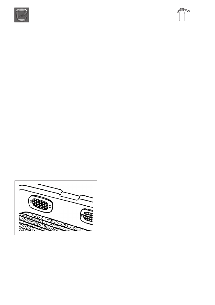
Low-Level Ventilation
The vents built into the step by the main
entrance door provide lowlevel ventilation.
These vents should be kept clear and
cleaned regularly using soapy water.
Gas Dispersal Holes
All appliances and gas unions have a gas
dispersal hole nearby. It is essential that
these are not blocked or made ineffective.
FIRE SAFETY
Fire Extinguishers
It is recommended that a 1 kg (21b) minimum
capacity dry powder fire extinguisher be
carried inside your motorhome at all times. A
pan fire must not have an extinguisher aimed
at it, but must be smothered with a fire
blanket.
In Case Of Fire
(i) Get everyone out of the motorhome as
quickly as possible using whichever exit
is quickest including windows. Do not
stop to collect any personal items.
(ii) Raise the alarm. Call the fire brigade.
(iii) Turn off the gas container valve if safe to
do so.
Fire Retardant Foams
All motorhomes are equipped with either
Combustion Modified High Resilient (CMHR)
foam cushions or sprung mattresses and fire
retardent fabric. All furnishings and fabrics
used by Elddis comply with the Furniture and
Furnishings (Fire Safety) Regulations. In
addition all upholstery is made of fire
retardant fabric.
Ventilation in Separate Bedrooms
In motorhomes with separated sleeping
areas, separate ventilation is required and is
provided via a roof skylight at high level and
a ventilator at low level within a bed box.
2-2
PREPARING FOR THE ROAD
PREPARING FOR THE ROAD
Before venturing out on to the road with your
motorhome, it is important that you prepare
correctly.
MOTORHOME WEIGHTS EXPLAINED
Mass in Running Order
The weight of your motorhome as it leaves
the factory, as new with standard fixtures and
fittings, plus an allowance for the driver of
75kgs and the mass of the fuel when the tank
is full, 90% of the water carried in the water
tank and an allowance for the gas bottles.
Maximum Technically Permissible
Laden Mass
The maximum mass the vehicle can be when
fully laden for use on the road.
User Payload
The load margin (payload), this represents
the difference between the Mass in Running
Order and the Maximum Technically
Permissible Laden Mass. It shows the
maximum weight that can be loaded into your
motorhome, covering items such as food,
crockery, cutlery, clothing, bedding, etc.
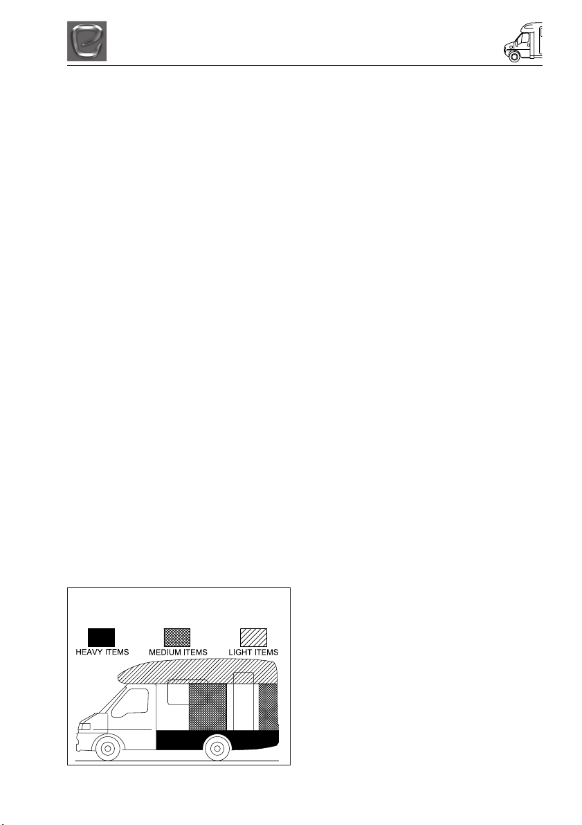
Loading
It should be noted that even weight
distribution is a major factor in making your
motorhome an easy and pleasant vehicle to
drive. Care should therefore be taken in
balancing the load, ensuring that heavy items
are well spaced and are in as low a position
as possible, for example, low cupboards and
bed boxes.
SENSIBLE LOADING
HOW TO APPORTION WEIGHT
Note: Light items are considered as clothing
and bedding. It is not recommended to travel
with tinned items in overhead lockers.
IMPORTANT: Do not exceed maximum
technical permissible laden mass for your
motorhome.
Roof Racks
Some models of motorhomes have, available
as an option, a roof rack and ladder. Care is
needed when using this facility. We
recommend you exercise extreme caution
when loading and unloading.
CAUTION: Do not allow anyone to climb onto
the roof. Do not exceed the stated maximum
load. Items fitted other than standard
equipment will deplete the payload stated in
this handbook.
Roof Loading
All motorhomes have a specially designed
roof rack system fitted or available as an
optional extra. The roof of each motorhome is
strengthened to accommodate the roof rack.
Please note: The roof rack is capable of
withstanding a maximum weight of 12 stone/
76kgs. Static roof loading or top box loading
should be limited to a maximum of 76kgs
including contents, or the limit set by the top
box manufacturer, whichever is the lower
figure.
WARNING: Under NO circumstances walk
on the roof section
Before venturing out on to the road with your
motorhome, it is important that you prepare
correctly.
Roof loads should be evenly distributed and
securely fastened, but care must be taken
not to overtighten straps or ropes to the point
where roof rails or brackets may become
distorted, particularly as during braking and
cornering, forces exerted by straps or ropes
are greatly increased.
It is also worth noting that when carrying
heavy or large objects on the roof, the
vehicles handling may change due to the
resultant displacement of the centre of gravity
and the increased area exposed to the wind.
3-1

PREPARING FOR THE ROAD
BEFORE MOVING OFF
Whenever making a journey with your
motorhome, either setting off on holiday or
returning home, it is good practice to run
through this simple checklist.
(i) Close and secure all cupboards and
drawers and secure any loose articles.
(ii) Do not store tins, bottles, etc. in
overhead lockers.
(iii) Close and secure all windows and
roof lights.
(iv) Leave all curtains and blinds open to
aid visibility.
(v) Check that gas cylinders are securely
fastened and that the valve on the gas
cylinder is turned off. Also ensure that
the gas locker door is securely locked.
(vii) Switch off 240volt supply at source;
disconnect mains cable and store in an
appropriate place.
(viii) Check that the battery is secure and
that the battery box door is locked.
(ix) Ensure the fridge is on 12V operation
and door lock is set.
(Note: the electrical relays will allow
the fridge to be run on the vehicle
battery when the engine is running.)
(x) Remove any external fresh water
connections etc.
(xi) Make sure any heavy articles are
stored in accordance with the loading
procedure.
(xii) Lock the motorhome habitation door
(remember to take out your keys).
(xiii) Check your external rear view mirrors
and adjust if necessary.
(xiv) If a step is used, ensure it is put away
before moving off.
(xv) Your new Elddis motorhome has been
designed to carry passengers in
designated passenger seats only. The
fitting of a 3-point seat belt can identify
these seats. Any seat not fitted with a
3-point seat belt is not designated as a
passenger seat.
(xvi) You are strongly recommended not to
carry passengers unless they are
seated in a designated passenger
seat.
(xvii) Ensure all tables have been stored in
their designated table storage position.
(xviii) Ensure you remove all items from the
microwave and cocktail cabinet before
setting off.
Pulling Off
• Pull away smoothly.
•Avoid wear and tear on clutch and
transmission by taking extra care.
• Change gears smoothly.
•Try not to jerk the clutch.
Bicycle Racks
Fitting a bicycle rack to the rear panel of a
motorhome will affect how weight is
distributed. There are restraints to be aware
of with such fitments.
The maximum loading allowed on the back
panel is 75 kgs including the weight of the
bike rack and bicycles.
The motorhome must also be balanced to
take into account the new weight distribution.
Weight must be distributed evenly.
Bicycle racks are not standard fit or supplied
as an optional extra by Elddis. Elddis cannot
be held responsible for problems related to a
bicycle rack fitted by a third party. A copy of
the rear panel drawing must be obtained by
the retailer or service centre from Elddis to
ensure correct fixing points are located.
Tow Bars
Your new Elddis motorhome has been
designed to accept a Witter tow bar. This has
been approved via type approval to ensure it
is safe to use and is the only tow bar
approved for fitting to Elddis motorhomes.
The maximum load allowed on the tow ball is
100kgs and the maximum overhang is
specified by the tow bar when fitted. The
fitting points for the tow bar are designated
by the fixing hole in the Witter extensions
fitted to the Peugeot chassis and full details
are available upon request from Elddis.
3-2

MOTORWAY HANDLING
MOTORWAY HANDLING
Best Practice
To gain the most enjoyment and ensure a
long life for your motorhome, the following
should be observed:
• Do not bump kerbs with wheels.
• When overtaking ensure sufficient
clearance is given to other vehicles.
•Your motorhome will not accelerate as
quicly as a car, so take this into account
when attempting to overtake other
vehicles.
• Carry out all manoeuvers as smoothly as
possible.
• Use the wing mirror to check your
motorhome has cleared has cleared the
other vehicle.
•Slow down and take care when driving
over raised speed bumps, ‘sleeping
policemen’ or when embarking/
disembarking ferries.
•In high or cross winds, travelling downhill
or in conditions of poor visibility reduce
your speed.
•High-sided vehicles can cause air
buffeting so extra care must be taken
when passing or being passed. Leave as
much space as possible when overtaking
these types of vehicles
Speed Limits
Be sure to observe all statutory speed limits
and adapt your speed to take account of
prevailing weather and road conditions.
Towing Your Motorhome
In the unlikely event that you have to tow
your motorhome, the towing point is fitted
within the front bumper, behind the
removable flap provided by Peugeot. The
towing hook can be found in the tool box
supplied by Peugeot, found under the front
passenger seat.
4-1

MOTORWAY HANDLING
4-2
ARRIVING ON SITE
ARRIVING ON SITE
CHECK SITE REGULATIONS
On arrival at a campsite, you should always
check the site regulations. This will help avoid
any unnecessary conflict with site
management and other site users.
SELECTING A PITCH
Carefully select where you wish to place your
motorhome. The site should be as level as
possible, preferably not under or near trees,
well drained and away from possible boggy
areas. Consider how you will move the
motorhome when it is time to leave the site.
On sloping ground it is better to pitch facing
downhill, especially during wet weather.
LATERAL LEVELLING (SIDE TO SIDE)
A quick glance at your pitch should tell you if
you are likely to need side to side leveling i.e.
levelling across the axle. On uneven ground
lateral levelling is accomplished by the use of
a leveler jack or ramp and a spirit level
placed ‘across’ the motorhome floor.
LEVELLER JACK
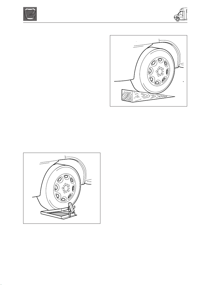
RAMP
Reverse onto your pitch about a foot further
back than you wish to end up. Then place the
levelling ramp in front of the wheel that needs
to be raised.
Place a spirit level parallel to the axle or just
inside the motorhome door. It helps to have
two people at this point. One should drive the
motorhome very slowly forward moving the
wheel up the ramp, and the other should
indicate when the spirit level bubble is in the
middle.
Whichever method you use, once level,
apply the motorhome handbrake and chock
the motorhome wheel if necessary.
Place the leveller jack, folded flat, in front of
the wheel that is to be raised to level the
axle. Drive the motorhome onto the leveler
jack and adjust the height until the spirit level
shows that the motorhome is laterally level.
5-1

ARRIVING ON SITE
5-2
GETTING STARTED
GETTING STARTED
You have arrived at your destination and now
want to start to enjoy your new Elddis
motorhome. The following is a step by step
guide to connecting your services and getting
everything in your motorhome working.
ELECTRICITY
Power Supply Charger
Your motorhome is fitted with a power supply/
charger. This will charge the motorhome
leisure battery when fitted and also power the
12V systems in your motorhome.
It is recommended that you always carry a
leisure battery.
The Charger is fully automatic and will not
overcharge the leisure battery.
Elddis recommend that you fit a good leisure
battery rated at least 85 amp hours.
12v Systems:
Your motorhome is fitted with an automatic
system for selection of power.
When connected to the 230V site supply the
automatic Power Supply/Charger will charge
the leisure battery and the 12V systems.
When the ignition is switched on the 12V
system in the motorhome is automatically
switched off, vehicle power is supplied to the
refrigerator and battery charging is in
operation.
GENERATOR/CHARGER
When connecting to a generator, always
switch off the RCD (residual current device),
start the generator and allow running for a
few minutes to stabilise. When this has
happened, switch the RCD to the ON
position.
ELECTRICITY MAINS SUPPLY
Your motorhome’s main electrical installation
is designed to run on 230V at 50 hertz AC
supply.
CONNECTING TO MAINS SUPPLY ON
ARRIVAL AT SITE
Before connecting the motorhome installation
to the mains supply, check that:
(i) The mains supply is suitable for your
installation and appliances, i.e. whether
it is AC or DC and whether it is at the
correct voltage and frequency.
(ii) Your motorhome is properly earthed.
Never accept a supply from a socket
outlet or plug having only two pins, or
from a lighting outlet.
(iii) Any residual current device (earth
leakage circuit breaker) in the mains
supply to the motorhome has been
tested within the last month. In case of
doubt, consult the site owner or their
agent.
(iv) Make sure that the switch at the site
supply point is off and that all electrical
equipment in the motorhome is switched
off by ensuring your motorhome mains
isolating switch on the MCB (miniature
circuit breaker) is in the ‘OFF’ position.
Once the above checks have been made:
(v) Remove any cover to the electricity inlet
provided on the motorhome, and insert
the female connector of the flexible
orange supply cable as shown.
(vi) Locate the site supply and remove any
cover from the socket outlet provided at
the supply point. Insert the male plug at
the other end of the flexible orange
supply cable. Switch on the main switch
at the site supply point (if appropriate).
6-1
GETTING STARTED
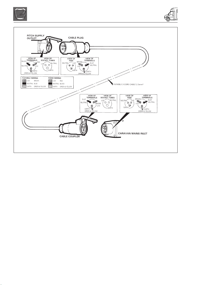
WIRING OF CONNECTING CABLE AND MOTORHOME MAINS INLET
WARNING: It is essential that connections are made exactly as shown. If terminal
markings are not in accordance with the above diagram they must be ignored.
(vii) Place any surplus cable under the
motorhome. Ensure that the surplus
cable is not coiled up as it could
overheat.
(viii) The MCB main electricity supply switch
should be put in the ‘ON’ position.
(ix) Check the RCD is working by pressing
the test button. Once pressed all
electrical lights and appliances should
cease to operate. Reset, and then check
the electrical system is operational.
(x) Finally in order to get your 12V system
operational, ensure the master 12V
switch is in the ‘ON’ position.
DISCONNECTING MAINS SUPPLY
WHEN LEAVING SITE
(i) Switch ‘OFF’ at the motorhome mains
isolating switch.
(ii) Remove the male plug from the site
supply.
(iii) Disconnect the female plug from the
motorhome and store the cable in an
appropriate locker.
OVERSEAS ELECTRICAL
CONNECTION
Please Note: Connection to a mains voltage
supply OVERSEAS requires particular
attention.
Care must be taken when connecting
supplies abroad since the supplies can be of
REVERSE POLARITY.
The significance of REVERSE POLARITY is
that when equipment is switched off, it may
not be electrically isolated. The only certain
way of making equipment safe is to unplug it.
A means of checking the polarity of the mains
supply when overseas is recommended.
There are available several proprietary
makes of equipment for the purpose.
If it can be achieved, it is preferable to
connect live to live and neutral to neutral to
maintain full electrical protection.
CHECK all motorhome equipment is set-up
to accept the site supply before actually
switching on.
6-2
GETTING STARTED
GAS SUPPLY
Your motorhome is designed to operate using
either propane or butane liquefied petroleum
gas at 30M/bar. Gas can be obtained from
your motorhome dealer. Your motorhome is
designed to accept a maximum 2 x 6kg Calor
Lite propane cylinders available from
motorhome dealers and Calor gas retailers.
For further information please visit
www.calorlite.co.uk.
Connection
Make sure that heating and cooking
appliances and gas cylinders are switched
off.
Each gas appliance is connected to its own
gas isolation tap under the cooker. These are
identified on the tap via a label. Below is a
key to identify each label.
To operate the tap the arrow on the tap
shows the direction of flow for the gas. The
arrow should be pointing towards the
appliance for the appliance to operate. There
will be a small label next to the bank of taps
under the cooker, which is also reproduced
below:
Water Heater
Space Heater
Refrigerator
Cooking Appliance
Hob
Gas On/Off
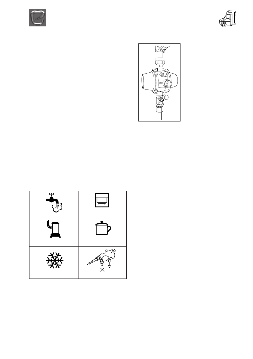
Gas Regulator
Your Motorhome is
fitted with a Road safe
gas regulator.
The operating
instructions are given
below.
Intended use
The Truma SecuMotion
gas-pressure regulator is
a device that ensures
uniform gas pressure (30
mbar) with a permissible
inlet pressure range of
0.3 - 16 bar.
SecuMotion regulates and monitors the
consumption of liquid gas. If the specified
consumption is exceeded or if the pressure at
the regulator outlet falls below 27 mbar (due
to gas pipe break, for example), the integrated
gas flow monitor will shut off the flow of gas. A
high pressure hose with a hose-break safety
device is essential for connecting the
SecuMotion gas pressure regulator to the gas
cylinder.
Truma offers hoses with common connection
fittings to enable use of gas cylinders with
various valve connection sizes.
Your Motorhome has been supplied with a
hose for connection to a propane gas
bottle.
The integrated overpressure safety device
complies with the requirements for a
commercial safety device against
impermissible pressure increases throughout
Europe, a type tested liquefied-gas heating
system may be used while driving (according
to the EU directive 2001/56/EC) if the system
includes a regulator with an appropriately
configured gas installation.
Pressure regulating devices and hoses must
be replaced with new ones no more than 10
years after their date of manufacture (every 8
years if used commercially). This is the
responsibility of the operator.
6-3

GETTING STARTED
ROAD SAFE GAS REGULATOR
Operating instructions
The use of upright gas cylinders from which
gas is taken in the gas phase is mandatory
for the operation of gas regulators, gas
equipment and gas systems. Gas cylinders
from which gas is taken in the liquid phase
(e.g. for fork lifts) must not be used, since
they would result in damage to the gas
system.
Taking into operation
Open gas remote switch if present.
1. Open the cylinder’s valve.
2. Firmly press the green reset button on
the high pressure hose.
3. Press gas flow monitor reset button
(green button) on gas pressure regulator
slowly.
4. Release gas flow monitor reset button
(green button) on gas pressure regulator
slowly (3 seconds). If no pressure point
is felt when the button is pressed again,
the regulator is ready for operation
(repeat procedure if necessary). Start
the gas-burning devices if desired. If the
gas cylinders are closed, SecuMotion
may switch off after an extended period
of no usage.
Changing a gas cylinder
Please use the included screwing tool to
attach and remove the high pressure hoses.
It will help you generate the necessary
tightening torque and will prevent damage to
the screw fittings, which may otherwise result
from using an improper tool.
When the cylinder is connected please
ensure that the high pressure hose is not
placed under any strain.
Residual gas: No smoking! No open
flames!
-Close the empty gas cylinder’s valve.
- Remove the high pressure hose from the
gas cylinder and remove the clip-on
adapter, if present.
-Attach the high pressure hose to the full
gas cylinder and apply the clip-on adapter,
if present.
- Open the full cylinder’s valve.
- Press the hose-break safety device and
the gas-flow monitor (see “Taking into
operation”).
Anytime after making changes, check the
hose connection to the cylinder valve for
leaks (see “Checking for leaks in the high
pressure area”).
Exchanging hoses.
Please use the included screwing tool to
attach and remove the high pressure hoses.
It will help you generate the necessary
tightening torque and will prevent damage to
the screw fittings, which may otherwise result
from using an improper tool.
Residual gas: No smoking! No open
flames!
-Close the gas cylinder’s valve.
- Remove the high pressure hose from the
gas cylinder (or from the slip-on adapter)
and from the regulator inlet.
When performing a hose change, please
ensure that the white gasket provided with
the hose (hose outlet - regulator inlet) is
correctly installed and not damaged.
We recommend that the gasket (part no.
50020-76300) be replaced with every hose
change.
- Screw country-specific high pressure hose
to SecuMotion inlet and cylinder (or to
adapter).
Open the gas cylinder’s valve.
- Press the hose-break safety device and, if
necessary, the gas-flow monitor (see
“Taking into operation”).
Anytime after making changes, check the
hose connections to the cylinder valve and to
the inlet of the SecuMotion gas-pressure
regulator for leaks.
6-4

GETTING STARTED
High Pressure Gas Hoses
You should only connect to this regulator
using a length of approved high-pressure
hose not exceeding 450mm from the gas
cylinder to the regulator. These approved
high-pressure hoses are available from your
Elddis Retailer. These hoses are connected
using screw thread fittings, which will make a
seal if connected and tightened using a
spanner. Once the hose is securely
connected turn on the gas tap above the
regulator, then turn on the gas bottle to allow
gas to flow into the motorhome.
In order to make all your motorhome gas
appliances operational it is necessary to
open each appliance gas tap as detailed in
previous column. All your gas appliances
should now be operational. Instructions on
how to use each appliance are detailed later
in your handbook.
WARNING: Aerosols and highly flammable
liquids must not be stored in the
compartment behind, or adjacent to, any
gas appliance. Some industrial LPG
appliances operate at high pressure and
require a ‘high pressure’ regulator. This
often has an adjusting handle on it.
NEVER use such a regulator on a
motorhome.
Ventilation holes must be clear at all
times.
WATER SYSTEM
Filling your fresh water tank
Your Aspire motorhome is fitted with a
standard water inlet which can be filled using
a hose pipe connected to a tap placed into
the water filler point.
Please take care not to over fill your tank it is
advised that someone monitors the water
level in the tank while filling is in progress.
Waste Water Tank
Your new Elddis motorhome is also fitted with
a 70Litre waste water tank. All waste water
excluding the toilet waste will run into the
waste water tank. The level of water in the
tank can be monitored using the control
panel. Opening the grey waste outlet
provided on the outside of the motorhome
empties the tank. Open the tap when the
outlet is over a drain and the water will run
out of the tank.
Draining Down Your Water System
(i) It is essential that you drain down your
motorhome water system when it is not
in use. This is most important during
winter months to protect against frost
damage
(ii) Disconnect the water pump and switch
off power supply.
(iii) Open the safety drain valve on the water
heater located next to the water heater.
(iv) Open all taps and remove all plugs from
sinks and showers. Lever operated taps
should have the lever put into the up and
central position.
(v) Open both the blue and grey drain
outlets on the outside of your
motorhome.
(vi) Adjust the level of the motorhome to
ensure that the drain outlet is at the
lowest point of the motorhome.
After 30 minutes level the motorhome and
prepare it for storage if necessary.
6-5

GETTING STARTED
6-6

GAS SAFETY ADVICE
GAS SAFETY ADVICE
In the event of a suspected gas leak the gas
must be turned off using the isolation valve
on the gas bottle. A competent gas fitter
should then check the system before it is
used/reused.
Regularly check flexible gas hose, joints and
connections for tightness. Finally, make sure
that each gas appliance is working efficiently
to the recommendations of the appliance
manufacturers.
See Index - Ventilation
FACTS ABOUT LPG
• LPG is not poisonous.
•Bi-products are harmless.
• LPG is dangerous if all air and oxygen is
excluded.
• LPG has been given a smell by the
manufacturers in order to identify leaks.
• The gas is heavier than air and therefore
sinks to the lowest point.
AWNING SPACES, LPG AND
APPLIANCE EXHAUST
There is no danger of pollution of an
enclosed awning space from the LPG
exhaust from a refrigerator venting into it.
Space heaters may produce sufficient
exhaust to pollute the awning space, if it is
totally enclosed, from a general comfort,
smell and hygiene point of view. In extreme
cases there could be a build up of carbon
dioxide to a dangerous level. Motorhome
owners are advised to allow some fresh air
circulation in the awning space when such
appliances are in use.
Please note: Ventilation holes must be clear
at all times.
LPG GAS SYSTEM
Elddis does not recommend the use of any
external cylinders. All cylinders in use should
be within the gas locker provided. If you wish
to utilise a larger cylinder and have this
outside the gas locker then the connecting
hose must not exceed 750mm.
It is recommended that no flammable
material is stored or placed within 300mm of
any open flame. Your attention is also drawn
to the fact that the surface of the Space
Heater in your motorhome will get hot when
in use. You are advised not to use any
additional gas appliances outside your
motorhome.
Please ensure that you have read the
operating instructions for each gas appliance
contained in your Owners Information Pack.
Please ensure that any gas hose left
unconnected is protected from dirt or other
foreign bodies entering the hose.
7-1

GAS SAFETY ADVICE
7-2

ELECTRICAL SYSTEM
ELECTRICAL SYSTEM
12v POWER SUPPLY
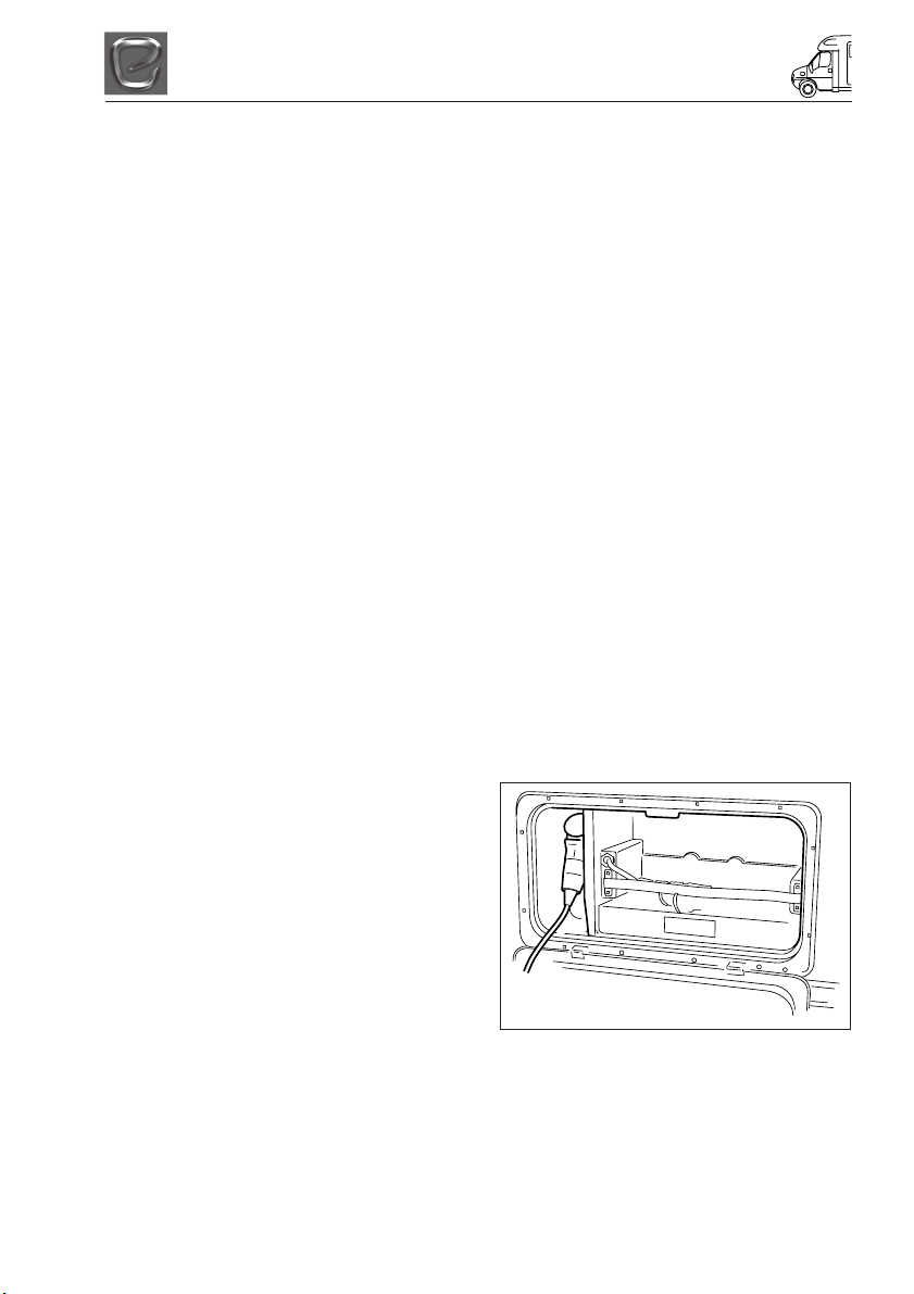
Battery Installation
Your motorhome will be fitted with a charging
and power distribution unit.
If you wish to install a leisure battery please
ensure that it is placed on the battery tray
supplied with your motorhome. Then place
the tray in the battery locker fitted to the side
of your motorhome. Connect the battery to
the clamp fittings connected to the
connection leads within the battery box.
Elddis recommends that you use sealed for
life leisure batteries of a minimum rating off
85 ampere-hours at 20 hours discharge rate.
Battery Maintenance
Your leisure battery should be maintained in
accordance with the manufacturer’s
instructions. For information on the automatic
charging system in your motorhome please
refer to ‘Automatic Charging System’ in the
index.
Do not charge your leisure battery with any
charger other than that supplied. Failure to
comply may cause damage to your battery. If
you remove your leisure battery, ensure that
it is not placed on a cold surface as the
battery will deteriorate more rapidly than if
stored at a suitable temperature
Generators / Charger
All electrical equipment fitted in your new
motorhome can be run from either a
controlled generator or charger whose output
is maintained between 11volts and 14volts.
At least once every 3 years, the motorhome
electrical installation should be inspected and
tested, and a report on its condition obtained,
as prescribed in British Standard BS7671.
230v POWER SUPPLY
Mains Unit
The Mains Unit replaces the conventional
fuse box. Similar, but larger ones are often
fitted in new houses. The unit, normally
located in the wardrobe, gives overloads and
earth leakage protection for the 230V
electrical supply in your motorhome.
For normal operation all switches on the unit
need to be in the ON position. The switches
on the left of the unit are known as MCB’s
(miniature circuit breakers). These take the
place of the conventional fuse but are more
convenient. In the event of a fault the MCB
‘trips’ i.e. automatically moves to the OFF
position. After elimination of the fault the
MCB can be re-set by switching to the ON
position (against the spring pressure in an
upwards direction). If an earth fault develops,
or a person was to touch a live piece of
equipment, the leakage of current to earth
should immediately operate the RCD
(residual current device) and ‘trip’ the main
switch, to the OFF position. This switch can
only be re-set after elimination of the fault.
Please note: In case of difficulty, consult an
approved electrical installation contractor
(who may be the local electricity board). It is
dangerous to attempt modifications and
additions yourself.
CAUTION: Lamp holder-plugs (bayonet- cap
adaptors) should not be used under any
circumstances.
Resetting the RCD
To re-set, operate the switch as for MCB’s.
Periodically, the RCD should be checked by
operating the test button marked ‘T’. The unit
should immediately switch to the OFF
position. If the unit does not switch off then a
qualified electrician should be consulted. If
the unit does switch off, the test is complete
and the switch can be re-set restoring the
supply back to normal.
Please note: Simultaneous operation of all
of the 230V mains electrical equipment may
not be possible. A typical UK site mains hookup point provides a maximum output of 16
amps and on some continental sites the
available output may be as low as 5 amps. If
your loading exceeds the site supply it may
trip the site circuit breaker. Please check the
available mains output with your site
operator. The following items need to be
added together if used simultaneously.
8-1

ELECTRICAL SYSTEM
230V mains equipment typical consumption
figures:
• Refrigerator ............................... 0.50 amps
• Charger ..................................... 0.50 amps
• Water heater ............................... 3.9 amps
• Blown air heaters ........................ 8.5 amps
• Colour TV .................................. 3.33 amps
AUTOMATIC CHARGING SYSTEM
The battery charger will operate automatically
when the motorhome is connected to the
mains outlet on a motorhome site. The 12V
system, with the exception of the 12V
refrigerator and battery charging, will not
operate when the motorhome when the
motorhome engine is running.
CHECK all motorhome equipment is set-up
to accept the site supply before actually
switching on.
INTERNAL LIGHTS
Your new Aspire motorhome is fitted with all
LED lighting.
You should not need to replace these long
life lights, however should the need arrive
please only replace these lights with identical
lights which are available from your Elddis
retailer.
MAXIMUM BULB RATINGS FOR
INTERNAL LIGHTS
Type of Light Maximum Bulb Rating
Front locker light ............................. 20 watts
Downlighters .................................. 1.2 watts
Reading lights ................................ 1.2 watts
Floor LED ..................................... 0.36 watts
Under locker strip lights 300mm .... 1.2 watts
Under locker strip lights 600mm .... 2.2 watts
Awning lights ................................... 10 watts
Please note: Ensure that you only replace a
blown bulb with one of the same rating.
Never replace a bulb with one with a higher
rating. You should ensure that when fitted,
no bulb is in contact with the surface of the
lamp or shade.
Note: All LED lights can only be replaced
with a new complete unit and not a
replacement bulb.
CAUTION: The reading lights will become
hot when in use. Do not touch the bulb when
they are illuminated and allow sufficient time
for them to cool after switching off. It is
recommended to set the position of the
reading light before switching on.
CAUTION: Do not look directly at LED lights.
8-2
HOW TO USE YOUR MOTORHOME’S EQUIPMENT
HOW TO USE YOUR
MOTORHOMES EQUIPMENT
Within this section of your motorhomes
handbook we will give you brief details on
how to operate all of the motorhomes
equipment from the gas cooking equipment
to the window blinds. For further details on
the major equipment within your motorhome
please read the individual appliance
instructions contained with your user
information pack.
Please note: Before attempting to use any
gas equipment please ensure that the gas
bottle is connected securely to the
motorhomes regulator via a high pressure
gas hose and the bottle valve is in the on
position. Also ensure the appliance isolation
valves are in the on position as shown in the
gas system section.
Please note: Before attempting to use any
electrical appliance please ensure that you
have connected the mains connection cable
to a mains hook up and that the mains
isolation switch is in the on position. Ensure
the 12V master switch is in the ON position.
This is found in the side of the unit next to the
entrance door.
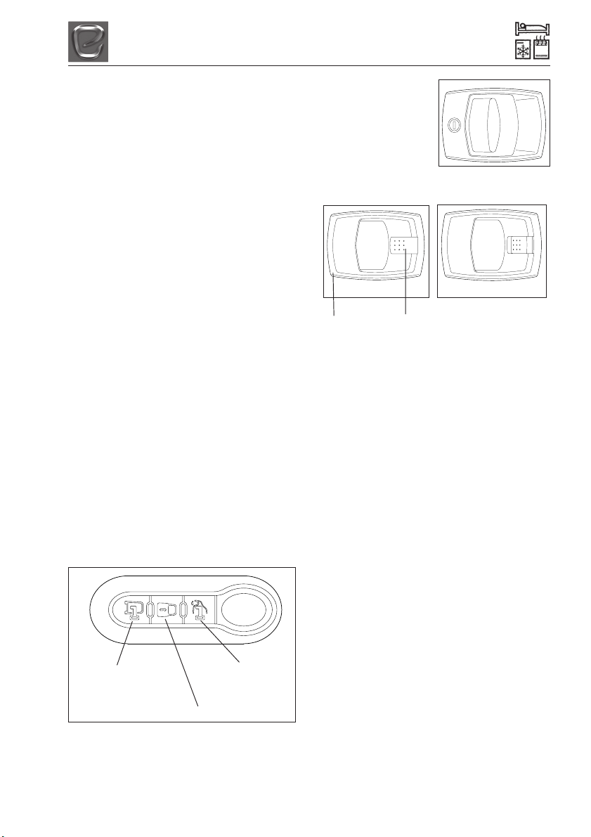
HOW TO OPERATE YOUR ASPIRE
MOTORHOME ENTRANCE DOOR
From the Outside
It is recommended that you always lock and
unlock your Aspire habitation door via the use
of the key fob shown below.
When pressed this
unlocks all doors
When pressed this locks all doors
When pressed this
locks just the cab
doors
Once you have
unlocked the entrance
door, to open the door
pull the lever shown
opposite.
From the inside
Door unlocked
Large
Lever
Locking
Button
Door Locked
Opening the door
Pull the large lever towards you and if locked,
the locking button will release. Pull the large
lever towards you again and the door will
open.
To close and lock your door
Pull the door closed to ensure it is fully
latched so that no visible light can be seen
past the door seal.
Now depress the locking button which can be
found in the centre of the handle.
To check the door is locked, try pushing the
door open without using the handle.
It is important that the locking button is in
the locked position before you start your
journey.
Please note: The main entrance door fitted
to your Motorhome is a burst proof door and
therefore requires more force to close it
before it can be locked.
Do not attempt to open or close the door
while the vehicle is in motion.
9-1

HOW TO USE YOUR MOTORHOME’S EQUIPMENT
High Pressure Gas Hoses
You should only connect to this regulator
using a length of approved high-pressure
hose not exceeding 450mm from the gas
cylinder to the regulator. These approved
high-pressure hoses are available from your
Explorer Group Retailer. These hoses are
connected using screw thread fittings, which
will make a seal if connected and tightened
using a spanner. Once the hose is securely
connected turn on the gas tap above the
regulator, then turn on the gas bottle to allow
gas to flow into the motorhome.
In order to make all your motorhome gas
appliances operational it is necessary to
open each appliance gas tap as detailed in
previous column. All your gas appliances
should now be operational. Instructions on
ELECTRICAL CONTROL PANEL
how to use each appliance are detailed later
in your handbook.
CAUTION: It is strongly recommended that
only Gas Safe Register™ approved gas
fitters carry out any work on your
motorhomes gas installation..
WARNING: Aerosols and highly flammable
liquids must not be stored in the
compartment behind, or adjacent to, any
gas appliance. Some industrial LPG
appliances operate at high pressure and
require a ‘high pressure’ regulator. This
often has an adjusting handle on it.
NEVER use such a regulator on a
motorhome.
Ventilation holes must be clear at all
times.
1 Button for control of car and leisure batteries
voltage (in Volt) and for the regolation of the
programmable parameters’ setting (see
SETTING).
2 Button for the control of drink water tank (in %),
for drinking water refilling function operation
(see “DRINK WATER TANK REFILLING”
function) and for the regolation of the
programmable parameters’ setting (see
SETTING).
3 “PROG” button for system setting (see
SETTING).
4 On/off main button (to turn on/off press for 2
seconds): at the start-up the display carries out
a functioning test and shows all symbols
(including unused symbols). If the relevant LED
is green the control panel is on, if it is red an
alarm is on (batteries, tanks, etc.).
5 Button to switch the lights on and off.
6 Button to switch the pump on and off.
7 Awning light button; this ext. light switches
automatically off when you start up the engine,
depends on the button rif.5.
NOTE: The watch is supplied from the leisure
battery (B2).
Should B2 be disconnected, the watch is able to
keep working, without visualisation, for about 2
weeks.
9-2
HOW TO USE YOUR MOTORHOME’S EQUIPMENT
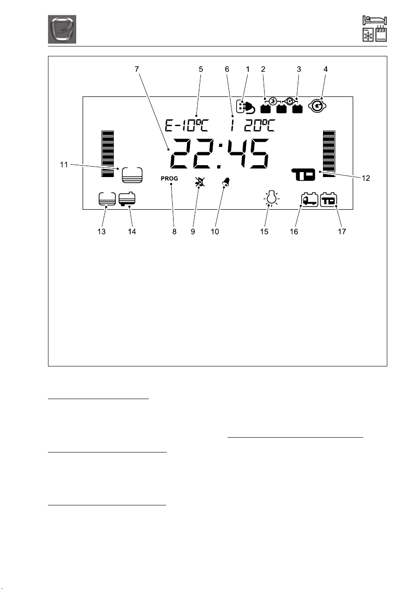
MAIN
DISPLAYS
1 It indicates that the 230V net is connected.
2 It displays that the car battery recharging
unit is on.
3 It displays that the battery parallel is on
when engine is on.
4 It indicates that the engine is on.
5 External temperature digital indicator.
6 Internal temperature digital indicator.
7 Clock digital display.
8 It displays the setting menu.
9 It displays that the tones are off.
FUNCTIONS
CAR BATTERY ALARM (B1)
When car battery voltage goes below 12V,
Car Battery Discharge alarm goes on and the
symbol ref. 16 starts blinking. Alarm goes off
when the voltage goes above 12.5V
CAR BATTERY RECHARGE (B1)
With battery charger: an electronic device
allows the recharge (max 2A) of car battery
(B1). Priority is given to leisure battery (B2)
charge.
LEISURE BATTERY ALARM (B2)
When leisure battery voltage reaches 11.5V
the leisure battery reserve alarm goes
automatically on, the symbol ref. 17 starts
blinking, you hear a short beep. When the
10 It displays that alarm clock is set.
11 Drinking water tank status display.
12 “B2” leisure battery status display.
13 It displays that the drinking water tank is
empty.
14 It displays that the waste water tank is full.
15 It displays the minimum voltage device is
on.
16 It displays that the car battery (B1) has run
down.,
17 It displays that the leisure battery (B2) has
run down.
leisure battery voltage reaches 10.5V, the
Leisure Battery Discharge alarm goes
automatically on, the symbol ref. 17 starts
blinking, you hear two short beeps. Alarms go
off when the voltage goes above 12.5V.
LEISURE BATTERY RECHARGE (B2)
a) Through engine alternator: through
spreader relays while engine is running. The
ignition controls the relays electronically:
parallel, fridge, awning light, etc.
b) trough 230V net: pad system through
battery charger.
c) trough solar panel: through solar charge
regulator.
9-3

HOW TO USE YOUR MOTORHOME’S EQUIPMENT
FUNCTIONS (continued)
MINIMUM VOLTAGE CONTROL (BATTERY
PROTECTION)
The electronic battery protection device
disconnects the 12V users when leisure
battery reaches 10V and disables: pump,
lights, awning light, stove, 12V sockets,
Omniventfans, motorised bed and TV
antenna. Symbol ref. 15 is the visual alarm
signal.
It is possible to connect all users for one
more minute by pressing the on/off button
(ref. 4 on control panel).
The control panel automatically turns off with
a voltage lower than 9.5V.
Users are automatically reconnected with a
voltage higher than 13.5V.
This device doesn’t control the the 12V users
connected directly to the leisure battery 132.
TANKS
a) Drinking water tank with electronic probe:
visualisation in % (steps of 5%). b) Waste
water tank with screw probe.
DRINKING WATER TANKALARM
Alarm turns on when drinking water level
goes below 15% of the tank capacity and
automatically turns off when level exceeds
25%. Alarm is acoustic (when engine is off),
visual (symbol ref. 13 blinking).
WASTE WATER TANK ALARM
Alarm turns on when the waste water level
exceeds the screw sensor level.
Alarm is shown acoustically (when engine is
off) and visually with the symbol ref. 14
blinking.
DRINKING WATER TANK REFILLING
This function is used during the drinking
water refilling and indicates the water level
during refilling.
To activate this function press the “test tank”
button ref.2 for more than 2 seconds, until the
“water refilling” is displayed on the screen.
The control panel beeps in order to warn that
tank is getting filled: one short beep at 75%,
two short beep at 85% and a long beep at
95%.
To exit this function press buttons ref. 1 or 2.
AWNING LIGHT AUTOMATIC TURN OFF
An electronic device switches off the awning
light when engine is turned on
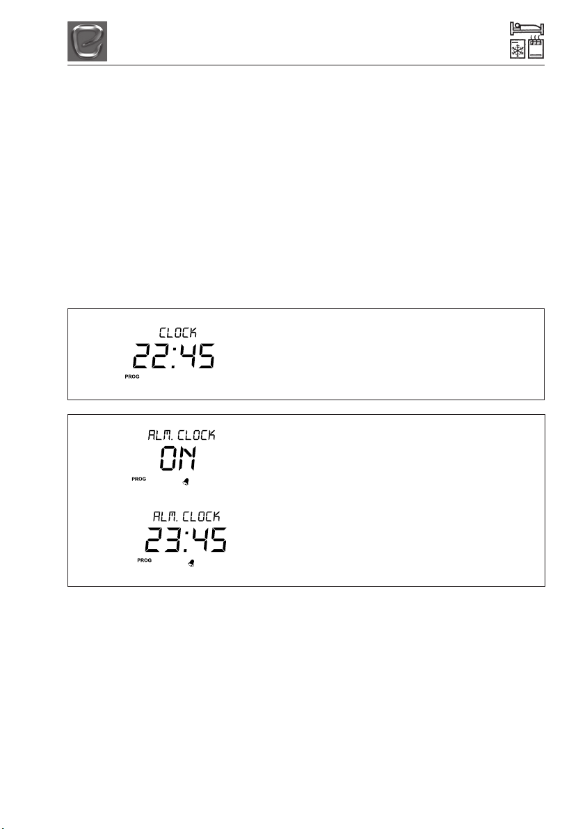
DIGITAL CLOCK
To set clock see “SETTING”.
ALARM CLOCK
To set and activate/deactivate the alarm clock
see “SETTING”. To reset alarm press any
test button; there is no delayed alarm!
TEMPERATURE
- Both int. and ext. temperatures have a
sensor, which is placed inside or outside of
the vehicle.
- The precision of the temperature value is ±1
°C.
ELECTRONIC BATTERY SEPARATOR
An electronic device controlled by the ignition
switches on the batteries parallel when the
car battery voltage is over 13,5V and
switches off when engine is off or voltage is
lower than 12.2V. This device operates only
if the B2 leisure battery is connected.
This device controls the relays of the users
depending from exit simulating +OUT D+ (3
way function fridge, awning light, antenna
motion, etc.).
9-4
HOW TO USE YOUR MOTORHOME’S EQUIPMENT
USER’S SETTING
•To enter the set mode, press the “PROG”
button (ref. 3) for more than 2 seconds
from the main clock screen.
• Select, by pushing the arrow keys ref. 1
and 2, the setting menu you want to
operate and then confirm by pushing the
“PROG” button ref. 3;
- by selecting “CLOCK” you operate the
menu to set only the parameters clock
and alarm clock
- by selecting “SYSTEM” you operate the
menu to set all parameters.
CLOCK SETTING
• By using the arrow keys ref. 1 and 2 you
can modify the setting of the parameters.
• Confirm the setting by pushing the
“PROG” button (ref. 3), you then go
automatically to next parameter.
• Press the “PROG” button (ref. 3) more
than once to save the settings and exit
the setting mode.
•To exit without saving wait 30 seconds
without pressing any key.
•Clock setting
- HOURS (blinking)
- MINUTES
(blinking)
• Activation of alarm clock
- ON (activation)
- OFF (deactivation)
• Set alarm clock time (only if alarm
clock has been previously activated)
- ON (activation)
- OFF (deactivation)
9-5
HOW TO USE YOUR MOTORHOME’S EQUIPMENT
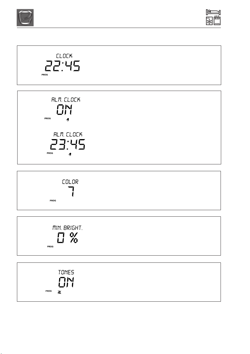
SYSTEM SETTING
•Clock setting
- HOURS (blinking)
- MINUTES
(blinking)
• Activation of alarm clock
- ON (activation)
- OFF (deactivation)
• Set alarm clock time (only if alarm
clock has been previously activated)
- ON (activation)
- OFF (deactivation)
• Backlight colour
selection
•Display’s backlight setting when
control panel is in stand-by
• Activation/Deactivation of acoustic
alarms
9-6
 Loading...