

elddis Buccaneer 2014, Crusader 2014 Owner's Handbook Manual

Buccaneer
Touring Caravan
OWNERS
HANDBOOK
Issue 5

CONTENTS
WELCOME AND INTRODUCTION ........ 1-1
Model Year .............................................. 1-1
Buccaneer Technical Approvals .............. 1-1
GENERAL SAFETY ............................... 2-1
Please read before using your
new caravan. ........................................... 2-1
Ventilation ............................................... 2-2
High-Level Ventilation ............................. 2-2
Low-Level Ventilation .............................. 2-2
Ventilation in Separate Bedrooms........... 2-2
Gas Dispersal Holes ............................... 2-2
Petrol/Diesel Fumes ................................ 2-2
Fire Safety ............................................... 2-2
Fire Extinguishers ................................... 2-2
In Case Of Fire ........................................ 2-2
Fire Retardant Foams ............................. 2-2
Your Caravan Payload Explained ........... 2-3
PREPARING FOR THE ROAD............... 3-1
Caravan Towing Vehicle Weight Ratio .... 3-1
Loading ................................................... 3-1
Internal Loading & Checks ...................... 3-1
External Loading & Checks ..................... 3-1
Pre-Tow Checklist & Hitch-Up ................. 3-2
Winterhoff Stabiliser - Hitch Head
Operation ................................................ 3-2
Activating the stabiliser ........................... 3-2
Checking the stabiliser ............................ 3-2
Uncoupling .............................................. 3-3
Use of Your Caravans Breakaway Cable 3-3
Handbrake .............................................. 3-5
Cables ..................................................... 3-5
TOWING AND DRIVING ......................... 4-1
Reversing ................................................ 4-1
Speed Limits ........................................... 4-1
Setting Off ............................................... 4-1
Caravan Handling ................................... 4-1
ARRIVING ON SITE ............................... 5-1
Check Site Regulations ........................... 5-1
Selecting a Pitch ..................................... 5-1
Side-To-Side Levelling ............................ 5-1
Leveller Jack ........................................... 5-1
Ramp ...................................................... 5-1
Front & Back Levelling ............................ 5-1
Parking on a Reverse-Sloping Site
or Steep Hill ............................................ 5-2
GETTING STARTED .............................. 6-1
Electricity ................................................. 6-1
Power Supply Charger ............................ 6-1
12v Systems: .......................................... 6-1
Generator/Charger .................................. 6-1
Electricity Mains Supply .......................... 6-1
Connecting To Mains Supply On
Arrival at Site ........................................... 6-1
Disconnecting Mains Supply
When Leaving Site .................................. 6-2
Overseas Electrical Connection .............. 6-2
Gas Safety Advice................................... 6-3
Facts about LPG ..................................... 6-3
Awning Spaces, LPG and Appliance
Exhaust ................................................... 6-3
LPG Gas System .................................... 6-3
Gas Supply ............................................. 6-3
Connection .............................................. 6-3
Changing a Gas Cylinder ........................ 6-4
Gas Regulator ......................................... 6-4
High Pressure Gas Hoses ...................... 6-4
Water System .......................................... 6-5
Water system control panel ..................... 6-5
How to Use Your Aquasource ................. 6-6
Connection to your water inlet ................ 6-6
Draining Down Your Water System ......... 6-6
ELECTRICAL SYSTEM .......................... 7-1
12v Power Supply ................................... 7-1
Battery Installation .................................. 7-1
Battery Maintenance ............................... 7-1
Generators / Charger .............................. 7-1
230v Power Supply ................................. 7-1
Mains Unit ............................................... 7-1
Resetting the RCD .................................. 7-1
Automatic Charging System ................... 7-2
Maximum Bulb Ratings for Internal Lights7-2
HOW TO USE YOUR CARAVAN’S
EQUIPMENT ........................................... 8-1
Cooking equipment ................................. 8-3
Gas Hob .................................................. 8-3
Gas Grill .................................................. 8-4
Gas Oven ................................................ 8-4
Refrigerator (RM8551) ............................ 8-5
Operation ................................................ 8-5
The control panel in standby mode ......... 8-8
From standby mode to setting menu ...... 8-8
Set the required temperature .................. 8-9
Extra warm water .................................... 8-9
Heating with electricity ............................ 8-9
Heating with gas ................................... 8-10
Unlocking the tool menu ....................... 8-10
Microwave ..............................................8-11
Battery Charger ...................................... 8-11
CONTENTS-1
MY2014/Buccaneer

CONTENTS
Smoke Alarm ..........................................8-11
Operation ............................................... 8-11
Nuisance Alarms ................................... 8-12
Maintenance ......................................... 8-12
Cleaning your alarm .............................. 8-12
Carbon Monoxide Alarm ....................... 8-13
Recognising alarm signals and
warnings ................................................ 8-13
Using your alarm ................................... 8-13
Switching on your CO alarm ................. 8-13
Re-setting the alarm .............................. 8-13
Replacement of batteries ...................... 8-13
Carbon Monoxide Alarm Procedure ...... 8-14
Maintenance of your alarm ................... 8-14
Dometic CT3050 Toilet.......................... 8-15
Description of parts ............................... 8-15
Cleaning ................................................ 8-16
Maintenance ......................................... 8-16
Dismantling the cassette seal ............... 8-16
Preparing cassette tank ........................ 8-16
Filling fresh water tank .......................... 8-17
Control panel ......................................... 8-17
Using the toilet ...................................... 8-18
Emptying the cassette tank ................... 8-18
Exchanging the fuse on the
control panel ......................................... 8-19
Winter use ............................................. 8-19
Decommissioning .................................. 8-19
Rooflights .............................................. 8-20
The Heki 4 Rooflight ............................. 8-20
The Omivent (12v) Rooflight ................. 8-20
Standard MPK Rooflight ....................... 8-20
Midi Heki Rooflight ................................ 8-21
Windows ............................................... 8-22
Polyplastic Window Opening ................ 8-22
Seitz Window Opening .......................... 8-22
Blinds & Flyscreens .............................. 8-23
Flyscreens ............................................. 8-23
Taps ...................................................... 8-23
Gas Locker Door ................................... 8-24
Internal Doors ....................................... 8-24
Magnetic Catches ................................. 8-25
Sprung Hinges ...................................... 8-25
Sliding Doors ......................................... 8-25
Paddle Lock .......................................... 8-25
Bed Make-up ......................................... 8-26
Front Wrap Round Seating (Option) ..... 8-26
Removable Drawer Locker ................... 8-27
Satellite Dish (Optional) ........................ 8-27
TV Avtex LCD Flat Screen TV ............... 8-27
Radio/CD with MP3 Connectivity .......... 8-27
Avtex Aerial ........................................... 8-27
Protect - Autowatch Alarm System ........ 8-28
BPW Intelligent Drive Control (iDc)
System .................................................. 8-29
SECURITY .............................................. 9-1
Caravan Theft ......................................... 9-1
Tracker .................................................... 9-1
Diamond Standard Wheel Lock .............. 9-2
How to fit your Diamond Standard
Wheel Lock ............................................. 9-2
Hints for using the Diamond
Standard Wheel Lock .............................. 9-2
Key Card ................................................. 9-2
Tracker .................................................... 9-3
Activation ................................................ 9-3
CRIS - The Caravan Registration and
Identification Scheme - VIN .................... 9-5
Window Etching & Chassis Marking ....... 9-5
Electronic Tagging ................................... 9-5
CARE OF YOUR CARAVAN ................ 10-1
Exterior Cleaning .................................. 10-1
Acrylic Windows .................................... 10-1
Care Instructions for Seitz Windows ..... 10-1
Care Instructions for Seitz Rooflights .... 10-1
Window Blinds & Flyscreens ................. 10-1
Winterisation/Storage ............................ 10-1
Interior Walls ......................................... 10-1
Furniture ................................................ 10-1
Cooking Equipment ............................... 10-2
Carpets, Upholstery and Curtains ......... 10-2
Shower Trays, Shower Room and
Wash Basin Fittings .............................. 10-2
Cleaning of all Taps ............................... 10-2
Water Containers .................................. 10-2
Water Systems - SteriliSation ............... 10-3
Thetford Toilet ....................................... 10-3
Chassis Mounted Spare Wheel Carrier 10-4
Tyres ..................................................... 10-4
Pressures .............................................. 10-4
Tyre Wear and Damage ........................ 10-4
Changing a Wheel ................................ 10-4
Jacking .................................................. 10-6
Lubrication ............................................ 10-6
Maintenance of your BPW Chassis ...... 10-7
Procurement of Spare Parts ................. 10-7
Caravan Motor Movers ......................... 10-7
STORAGE ............................................ 11-1
Long Term & Winter Storage ..................11-1
Caravan Covers ..................................... 11-1
Power Drain ........................................... 11-1
CONTENTS-2

CONTENTS
CARAVAN WARRANTY COVER ......... 12-1
non warranty repairs ............................. 12-3
Remedial Work...................................... 12-3
CARAVAN CONSTRUCTION -
MAIN COMPONENTS .......................... 13-1
BPW Chassis ........................................ 13-1
Braking System ..................................... 13-1
Solid Construction Body Shell ............... 13-1
Windows ............................................... 13-1
Insulation ............................................... 13-1
Front Panel and Gas Bottle Locker Door13-1
Awning Channel .................................... 13-1
EQUIPMENT LIST ................................ 14-1
Buccaneer ............................................. 14-1
ELECTRICAL DRAWINGS................... 15-1
13 Pin Plug Wiring Diagram .................. 15-1
Wiring Diagram - Buccaneer ................. 15-2
Road Lights - Buccaneer ...................... 15-3
GENERAL QUESTIONS ...................... 16-1
GLOSSARY .......................................... 17-1
SERVICE DOCUMENTS ...................... 18-1
NOTIFICATION OF CHANGE OF
OWNERSHIP ........................................ 19-1
NOTIFICATION OF CHANGE TO
NAME AND ADDRESS ........................ 20-1
INDEX ................................................... 21-1
CONTENTS-3

CONTENTS
CONTENTS-4

INTRODUCTION
WELCOME AND
INTRODUCTION
Congratulations on choosing a Buccaneer
Touring Caravan.
This Owner’s Handbook has been prepared
for your guidance to help you derive the
greatest amount of pleasure from the use of
your caravan and your leisure time. We
strongly recommend that you read this guide
thoroughly so that you are fully aware of all
the caravan’s features, equipment and
systems.
Additional information and detailed appliance
instruction manuals are also contained in
your Owner’s Information Pack.
Your new Buccaneer caravan has been
designed as a recreational vehicle and is
intended for recreational use only. It is not
intended for business, hire use or for
permanent habitation. Buccaneer accepts
no liability if the caravan is used for any
purpose other than recreational/holiday
use. Any other use other than
recreational/holiday use will invalidate
your warranty.
Your new Buccaneer caravan has been fitted
with a GRP underskin to the floor, this
reduces weight and provides a water
resistant barrier. This will eliminate the
problem of long term water damage and
rotten floor underside.
Your caravan has been designed for towing
behind a normal motor car. Additional care
should be exercised when towing with a 4x4
because of the ‘off-road’ nature of the
suspension. Owners should not tow their
touring caravans with commercial vehicles.
When selecting a towing vehicle it is
recommended that you consult the Caravan
Towing Code, which is available from the
NCC.
By following the instructions provided in this
handbook and maintaining your caravan in a
first class roadworthy condition, you are sure
to have many years of carefree use.
To ensure the very best quality and reliability
all touring caravan designs and new
developments are rigorously tested.
Therefore Buccaneer will accept no liability or
uphold the warranty if the caravan is altered
or modified in such a way that would
adversely affect the reliability.
Please note: It is a condition of your
warranty that the caravan must have an
“annual service” carried out by a Buccaneer
approved Retailer / Service Centre or NCC
Approved workshop and a record is kept.
Pages are provided in the back of this guide,
for your assistance.
A Buccaneer Approved Retailer / Service
Centre will be able to supply any replacement
parts for your caravan, should the need arise,
and in most cases any accessories you may
require.
Please note: It is not possible to purchase
replacement parts direct from Buccaneer.
Changing market and supply situations may
prevent us from maintaining the exact
specification details in this guide and we
therefore reserve the right to alter
specifications as materials and conditions
demand.
Enjoy your new caravan
Model Year
All Touring caravans manufactured by
Buccaneer are designated by their model
year. The 2014 model year runs from 1st
September 2013 to 31st August 2014.
Buccaneer Technical Approvals
All Buccaneer Caravans have been
European Commission Whole Vehicle Type
Approved via the Vehicle Certification Agency
(VCA).
In order to ensure your new caravan is safe
to use, Buccaneer are members of and have
been inspected by the following bodies.
NCC who operated a certification scheme to
ensure compliance with the European safety
standards for caravans.
National Inspection Council for Electrical
Installation and Contracting (NICEIC) who
carry out an annual inspection of Buccaneer
electrical installations within caravans.
Gas Safe Register™ approved installers
carry out an annual inspection to ensure that
the gas installations carried out by Buccaneer
1-1

INTRODUCTION
fully comply with all relevant regulations and
standards.
Buccaneer has also obtained ISO9001:2008
accreditation and this is audited by SGS UK
Limited
1-2

GENERAL SAFETY
GENERAL SAFETY
Please read before using your new
caravan.
In order for you to get the most out of your
new Buccaneer caravan it is necessary for
you to be aware of the following:
(i) Do not obstruct ventilators and clean
them regularly, it is advisable to clean
and check all the ventilators annually
for blockages and where necessary
rectify any blockages found.
(ii) Inspect the high pressure flexible gas
hose (available from your retailer)
regularly for deterioration and renew
as necessary, with an approved type,
in any case no later than the expiry
date stated on the hose.
(iii) Ensure the gas supply and all
appliances are turned off before towing
your caravan.
(iv) If your caravan has been fitted with a
gas BBQ it must be only used for its
intended purpose. Do not use a gas
barbeque within an awning.
(v) Never use portable cooking or heating
equipment inside your caravan. Do not
use your fitted cooking equipment as
heating at any time.
(vi) Never allow modification to your gas or
electrical system unless qualified
persons carry them out. All
modification to the gas system must be
carried out by a Gas Safe Register™
approved gas fitter. Any modifications
carried out on the electrical system
must be carried out by an electrician
on the roll of the NICEIC or be a
member of the ECA.
(vii) If you suspect there is a gas leak
please open all the windows then
vacate the caravan. Then contact your
nearest Buccaneer Retailer to arrange
for them to check the gas system.
(viii) In the interest of safety, replacement
parts for an appliance should conform
to the appliance manufacturer’s
specifications and should be fitted by
them or an authorised agent.
(ix) It is recommended that you provide a
dry powder fire extinguisher complying
with ISO 7165 of at least 1KG capacity
by the exit door and a fire blanket next
to the cooker. Ensure you read the
‘advice to occupier label’ fitted to your
caravan usually found on the inside of
the wardrobe door.
(x) Never exceed your caravans Maximum
Technical Permissible Laden Mass.
(see Caravan Towing Vehicle Weight
Ratio).
(xi) The laden nose weight for your
caravan should not exceed the lower
of the following:
•Towing vehicles maximum nose
weight.
•Tow bar maximum nose weight.
• The caravan’s maximum nose weight
(xii) Ensure heavy and large items are
secured before towing your new
caravan to reduce the risk of damage
being caused while the caravan is in
motion.
(xiii) Pull out worktop extensions, where
fitted, are only designed to take
maximum weight of 6kgs.
(xiv) When your caravan is connected to
your towing vehicle it should be level
or slightly nose down. However, in the
UK the maximum speed allowed for
towing a caravan is 100kmh/60mph.
(xv) When your caravan is loaded to its
MTPLM and the weight distributed in
accordance with the handbook, your
caravan is designed to be towed at a
maximum speed of 100kmh/60mph.
(xvi) It is illegal to tow your caravan
whilst it is occupied.
(xvii) Do not leave children under 14 years
of age unattended in your caravan.
IMPORTANT: Your attention is drawn
to the notice affixed in the caravan’s
wardrobe advising on fire
prevention, ventilation and what to
do in case of fire.
2-1

GENERAL SAFETY
VENTILATION
All caravans manufactured by Buccaneer are
ventilated at both high and low level in
accordance with BSEN 721 Safety
Ventilation.
High-Level Ventilation
This is always provided by fixed ventilation
within the fitted roof skylight. All roof skylights
fitted by Buccaneer provide fixed free area
ventilation. These roof skylights should be
cleaned annually by use of a small brush to
remove any dust that may have accumulated
around the mesh fitted. On some roof
skylights the mesh can be easily removed to
aid cleaning. On fan-assisted roof skylights it
is essential that the fan is switched off prior to
cleaning
Low-Level Ventilation
Low-level ventilation is provided under the
front chest of drawers. The exact position can
be identified via a cover used to prevent the
ventilation from being obstructed. In order to
clean the ventilator, remove the cover by
undoing the two screws and clean using a
small brush. It is essential that the cover is
replaced once cleaning is complete.
Ventilation in Separate Bedrooms
In caravans with separated sleeping areas,
separate ventilation is required and is
provided via a roof skylight at high level and
a ventilator at low level within a bed box or
under the fixed bed.
Gas Dispersal Holes
All appliances and gas taps have a gas
dispersal hole nearby. It is essential that
these are not blocked or made ineffective.
Petrol/Diesel Fumes
The fitting of a tail pipe to your exhaust will
reduce the possibility of fumes entering your
caravan through the front fixed ventilation
points.
FIRE SAFETY
Fire Extinguishers
It is recommended that a 1 kg (2lb) minimum
capacity dry powder fire extinguisher be
carried inside your caravan at all times. A
pan fire must not have an extinguisher aimed
at it, but must be smothered with a fire
blanket.
In Case Of Fire
(i) Get everyone out of the caravan as
quickly as possible using whichever exit
is quickest including windows. Do not
stop to collect any personal items.
(ii) Raise the alarm. Call the fire brigade.
(iii) Turn off the gas container valve if safe to
do so.
Fire Retardant Foams
All caravans are equipped with either
Combustion Modified High Resilient
(C.M.H.R.) foam cushions or sprung
mattresses and fire retardent fabric. All
furnishings and fabrics used by Buccaneer
comply with the Furniture and Furnishings
(Fire Safety) Regulations. In addition all
upholstery is made of fire retardant fabric.
2-2

GENERAL SAFETY
YOUR CARAVAN PAYLOAD
EXPLAINED
Definitions
Plated maximum technical
permissible laden mass (PMTPLM)
As specified by Buccaneer and in compliance
with the European Directive on Masses and
dimensions of vehicles.
Actual MTPLM
Maximum mass of the vehicle, which takes
into account operating conditions including,
factors such as the strength of materials,
loading capacity of the tyres etc.
Mass of the caravan in running
order (MIRO)
This is the weight of your caravan as it
leaves our factory plus the following:
18kgs to allow for the carrying of 2 x
6kgs BP gas light bottles.
9kgs of water in the water heater.
Personal effects payload (PEP)
This is calculated by the following formula:
10L + 10N + 50
L is the body length of the caravan in
meters.
N is the number of berths.
50 is for normal equipment carried in the
caravan, a sample list is given below.
Kettle ................................... 0.5kgs
Bed linen ................................. 6kgs
Crockery ................................. 5kgs
Saucepans .............................. 3kgs
Wastemaster...........................6kgs
Aquaroll (empty) ..................... 5kgs
Waste bin ................................. 1kg
Cutlery .................................... 2kgs
To ilet fluid etc ....................... 2.5kgs
Battery .................................. 25kgs
Optional equipment payload (OEP)
This is an amount of weight provided by us
for factory fitted options.
Please note: Any options fitted by the
retailer will reduce the overall payload
available to the customer.
User Payload is the sum of the PEP and
OEP.
Note: It is possible to upgrade your Plated
MTPLM to the Actual MTPLM up to the
caravan being 3 years old, there is an
administration fee for this service.
Note: Please ensure you never load your
caravan above the plated MTPLM.
2-3

GENERAL SAFETY
2-4

PREPARING FOR THE ROAD
PREPARING FOR THE ROAD
Before venturing out on to the road with your
touring caravan, it is important that you
prepare correctly.
CARAVAN TOWING VEHICLE
WEIGHT RATIO
This ratio has a major influence on stability. It
is recommended that:
(i) The laden nose weight for your caravan
should not exceed the lower of the
following:
*Towing vehicles maximum nose
weight,
*Tow bar maximum nose weight
* The caravan’s maximum nose weight.
(ii) The actual laden weight of the caravan
should always be kept as light as
possible. The lighter it is whilst being
towed on a road, the safer the outfit
combination will be.
(iii) What you are able to tow is dependent
on your driving licence.
(iv) If you are a B licence holder you can
only tow a car/caravan combination of
total weight not exceeding 3500kgs and
the cars kerb weight must be greater
than the caravans plated MTPLM.
Note: It is strongly recommended that
the caravan plated MTPLM should not
exceed the cars kerb weight.
(v) If you hold a B + E licence you can tow
up to a combination weight of 7000kgs.
(vi) The greater the actual laden weight of
the caravan in relation to the kerb weight
of the towing vehicle the more careful
and experienced the driver needs to be
and the lower the speed at which
instability could occur.
WARNING: It is strongly recommended
the loaded weight of the caravan does not
exceed the kerb weight of the towing
vehicle.
LOADING
Always lower and secure the jockey wheel
and the four corner steadies (with the brace
provided) before entering the caravan. This
will ensure that the caravan does not tip up
when you are inside.
Please note: Corner steadies should not be
used as a jacking or levelling device.
Internal Loading & Checks
When loading your caravan it is advisable to:
(i) Distribute items evenly over the axle and
as low as possible to optimise road
holding and achieve the best possible
braking effect.
(ii) Do not overload on one side as this will
cause the caravan to lean and affect the
road holding and stability.
(iii) Do not stow tins, bottles or heavy items
in overhead lockers when towing.
(iv) Loose articles should be stowed
securely to avoid movement and
possible damage.
(v) Ensure that all lockers and cupboard
doors are closed and secured.
(vi) Secure all bunks (if appropriate).
(vii) Store the main dining table in its transit
position.
(viii) Set the refrigerator for 12V operation if
any fresh food is stored in it and ensure
the door is locked.
(ix) Fully close and lock all windows and
rooflights. Never tow with windows on
night setting.
(x) Leave all curtains and blinds open to
prevent damage in transit. If your
caravan has a rear window this may aid
visibility.
(xi) Ensure you remove all items from the
microwave and cocktail cabinet before
towing.
External Loading & Checks
(i) Gas cylinders should only be stored,
correctly positioned, and secured in the
gas bottle locker. The gas should be
turned off.
3-1
PREPARING FOR THE ROAD
(ii) The leisure battery is stored and
secured in the battery locker box, set
into the tray provided and secured.
(iii) Any external connections (battery
chargers, connecting cables etc), should
be disconnected and stowed.
(iv) Check that all exterior locker doors are
secure and locked.
(v) Secure and lock the main caravan
entrance door.
PRE-TOW CHECKLIST & HITCH-UP
Having loaded the touring caravan and
secured the lockers and main entrance door:
(i) Check touring caravan wheel bolts are
torque tightened to the required level
(See Index - Changing a Wheel).
(ii) Check tyre pressures (Refer to the
Technical Data Sheet) and tyre condition
for roadworthiness.
(iii) Ensure the jockey wheel is down, in
good contact with the ground, clamp
tightly secured, and the caravan
handbrake is fully on.
(iv) Wind up the corner steadies.
(v) Reverse the car close up to the
caravan’s hitch. It is advisable to seek
assistance to guide you so that the car
tow ball aligns with the caravan’s hitch.
(Use of the caravan handbrake is
advised. Extreme caution should be
taken if manoeuvring the caravan down
hill or on wet, slippery surfaces).
(vi) Make sure the jockey wheel height is
sufficient for the hitch head to clear the
towing vehicles tow ball.
(v) Manoeuvre the hitch head over the tow
ball and lower the jockey wheel using
the winding handle, until the hitch head
opening sits comfortably over the tow
bar ball.
WINTERHOFF STABILISER - HITCH
HEAD OPERATION
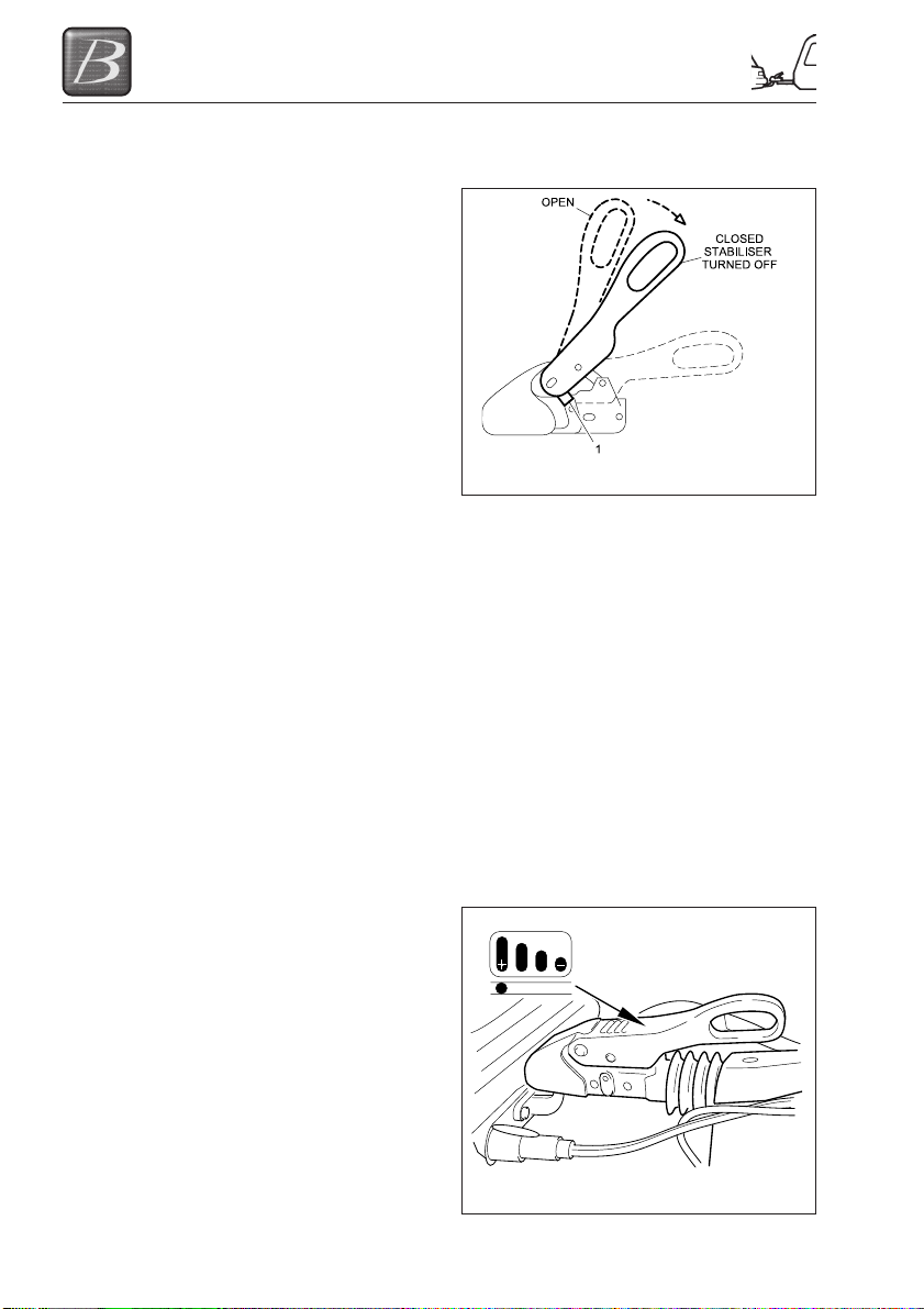
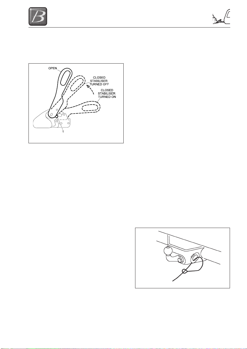
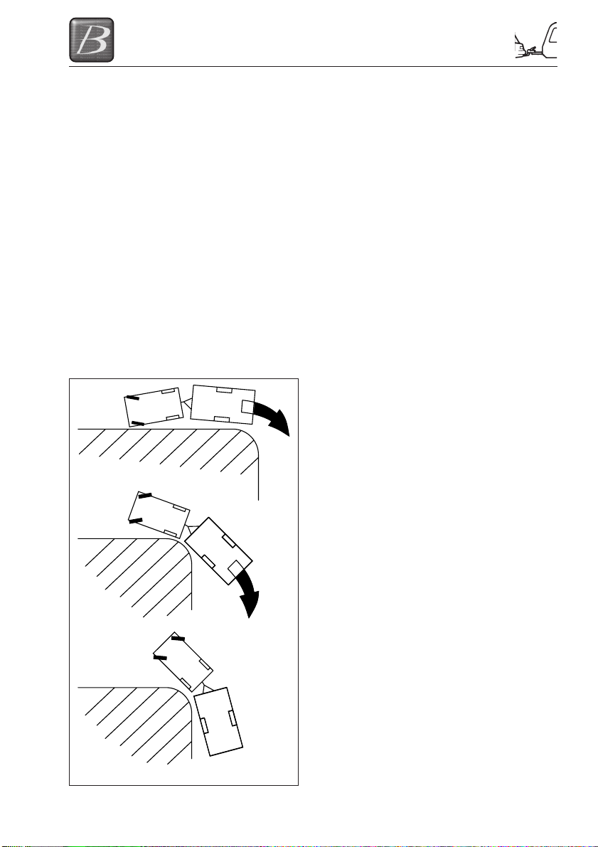
Coupling
The opened ball coupling is placed over the
tow ball of the towing vehicle. As the
coupling load is applied to the tow ball the
coupling will automatically close, this is
indicated when the security lugs become
parallel on the side of the housing. (Fig 3.1)
Fig 3-1
Activating the stabiliser
The operating handle will not operate until
the automatic closing function has been
engaged. The handle can now be fully
pushed down. The hitch will remain coupled
with the stabiliser deactivated to facilitate
easier manoeuvring.
Checking the stabiliser
With the caravan coupled to your towing
vehicle and the stabiliser activated, the
condition of the friction linings can be
checked. The wear indicator (as shown in Fig
3.2) is within the top of the operating handle.
The bar graph is marked with (+) and (-)
symbols with (+) indicating good condition of
the pads and (-) indicating that the pads
should be checked.
Fig 3-2
3-2
PREPARING FOR THE ROAD
Disengaging the stabiliser
Lift up the operating handle with care to
release the sprung loaded stabiliser function.
Uncoupling
Fig 3-3
Before uncoupling disconnect the electrical
connections and breakaway cable. Also
check that it is safe to uncouple your caravan
taking into account any gradients. With the
stabiliser function disengaged,
simultaneously pull back and lift the operating
handle, this swings the securing lugs out of
the locked position allowing the operating
handle to be lifted into the fully open position.
Before operating the jockey wheel, which will
lift the caravan free of the tow ball, check that
both caravan and towing vehicle handbrakes
are applied!
If the caravan is not to be used for any
lengthy period of time we recommend the ball
coupling is kept in the closed position. This
can be done easily by pressing the safety ball
into the ball space and slowly closing the
operating lever.
USE OF YOUR CARAVANS
BREAKAWAY CABLE
UK LAW requires that all caravans with
brakes (e.g. caravans, horse boxes, car
transporters etc), built on or after 1st October
1982, are fitted with a safety device to
provide protection in the unlikely event of the
separation of the main coupling while in
motion. It’s also a legal requirement to use
the breakaway cable whenever it’s provided.
The purpose of the breakaway cable is to
apply the caravan’s brakes if it becomes
separated from its towing vehicle. The cable
assembly is designed to part, allowing the
caravan to come to a halt away from the
towing vehicle.
Construction - Usually a thin steel cable,
possibly plastic coated, and fitted with a
means of attachment to connect to the towing
vehicle.
Operation - The cable should be able to pull
tight to engage the caravan’s brakes without
any hindrance to its action, if the main
coupling of the caravan separates from the
towing vehicle. It should never become taut
during normal use.
Correct Procedure For Use
(i) Check cable assembly for damage. If in
doubt contact your Retailer or Service
Centre.
(ii) Make sure the cable runs as straight as
possible, and goes through a cable guide
underneath the caravan coupling.
(iii) Determine whether or not you have a
designated attachment point (a feature of
the tow bar which has been identified by
the tow bar supplier as being for the
attachment of a breakaway cable).
Where a Designated Attachment
Point Is Provided On The Tow Bar
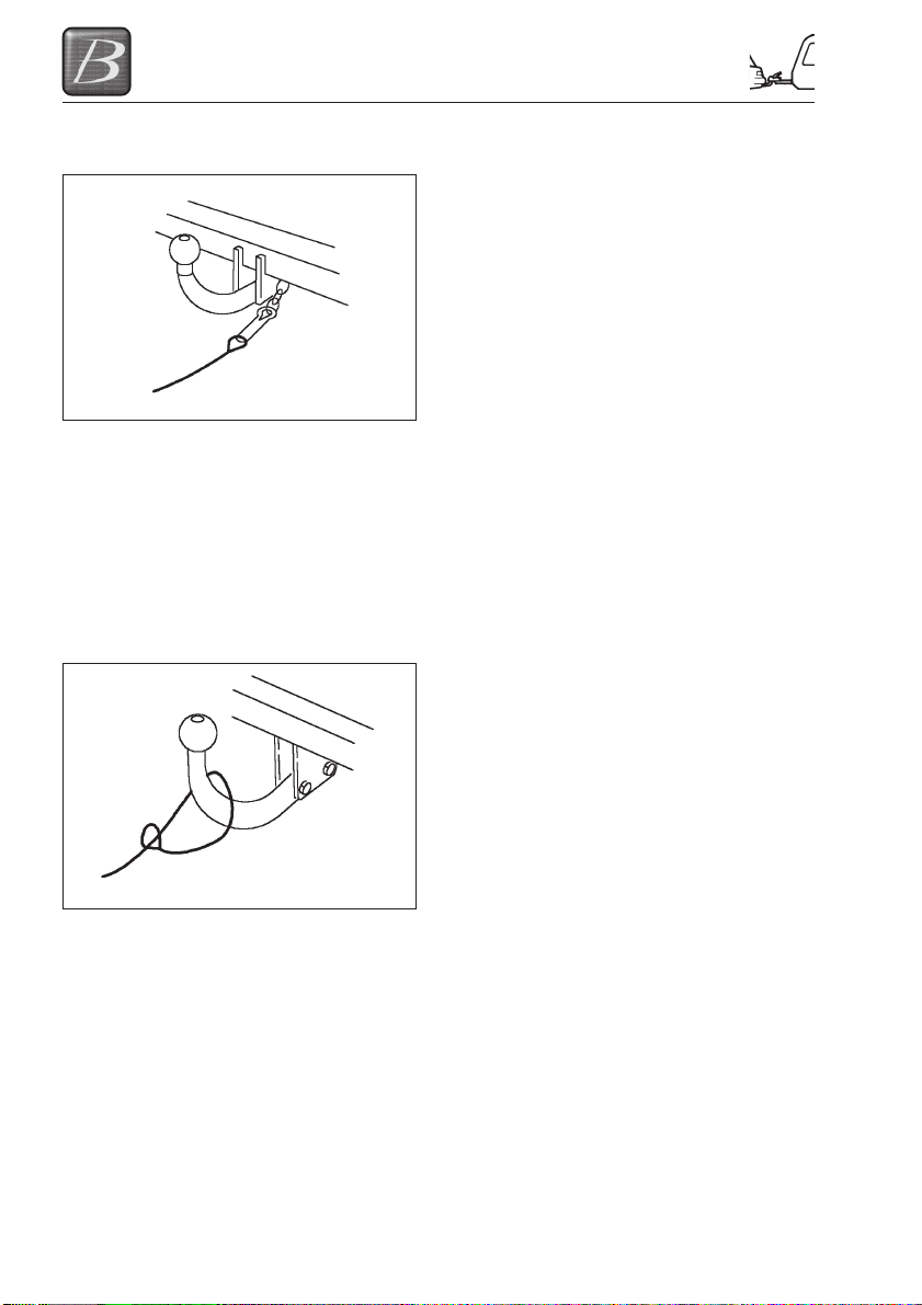
(i) Pass the cable through attachment point
and clip it back on itself (Fig 3-4, Step 1);
STEP 1
Fig 3-4
or
3-3
PREPARING FOR THE ROAD
(ii) Attach the clip directly to the attachment
point (Fig 3-5, Step 2).
STEP 2
Fig 3-5
Note: this must be specifically permitted by
the caravan manufacturer’s guidance, as the
clip may not be sufficiently strong.
Where No Designated Attachment
Point Is Provided On The Tow Bar
(i) Fixed Ball - Loop the cable around the
neck of the tow ball. If you fit the cable
like this use a single loop only (Fig 3-6,
Step 3).
STEP 3
Fig 3-6
(ii) Detachable Ball - You must contact the
tow bar supplier for advice.
Other Means of Attachment
Alternatively, it may be possible to attach the
cable assembly to a permanent part of the
tow bar structure with the approval of the tow
bar supplier, or to an accessory sold for the
purposes of breakaway cable attachment.
When The Breakaway Cable Is
Attached Check To Ensure
(i) That the cable cannot snag in use on the
caravan hitch, jockey wheel or any
accessories e.g. a stabiliser, bumper
shield, cycle carrier etc.
(ii) That there must be sufficient slack in the
cable to allow the towing vehicle and
caravan to fully articulate without the
cable ever becoming taut and applying
the brakes.
(iii) That it is not so slack that it can drag on
the ground. Leave it too loose, and the
cable may scrape along the ground, and
be weakened so that it fails before doing
its job!
BEFORE SETTING OFF
(i) Connect the 13 pin plug on the caravan
A-frame to the towing vehicle.
(ii) Check that all tail-lights, brake lights,
road lights and indicators work correctly.
(iii) Ensure that the correct vehicle license /
registration plate is attached to the rear
of the touring caravan.
(iv) Using the jockey wheel lift the tow ball
slightly to check hitch is locked onto the
ball
(v) Wind up the jockey wheel until the wheel
supports locate into the cut out sections
at the base of the winding section.
(vi) Raise and secure the jockey wheel
using the clamp. The jockey wheel
should be parallel to the direction of
travel at all times.
(vii) Check condition of and secure the
breakaway cable to the tow vehicle.
3-4
PREPARING FOR THE ROAD
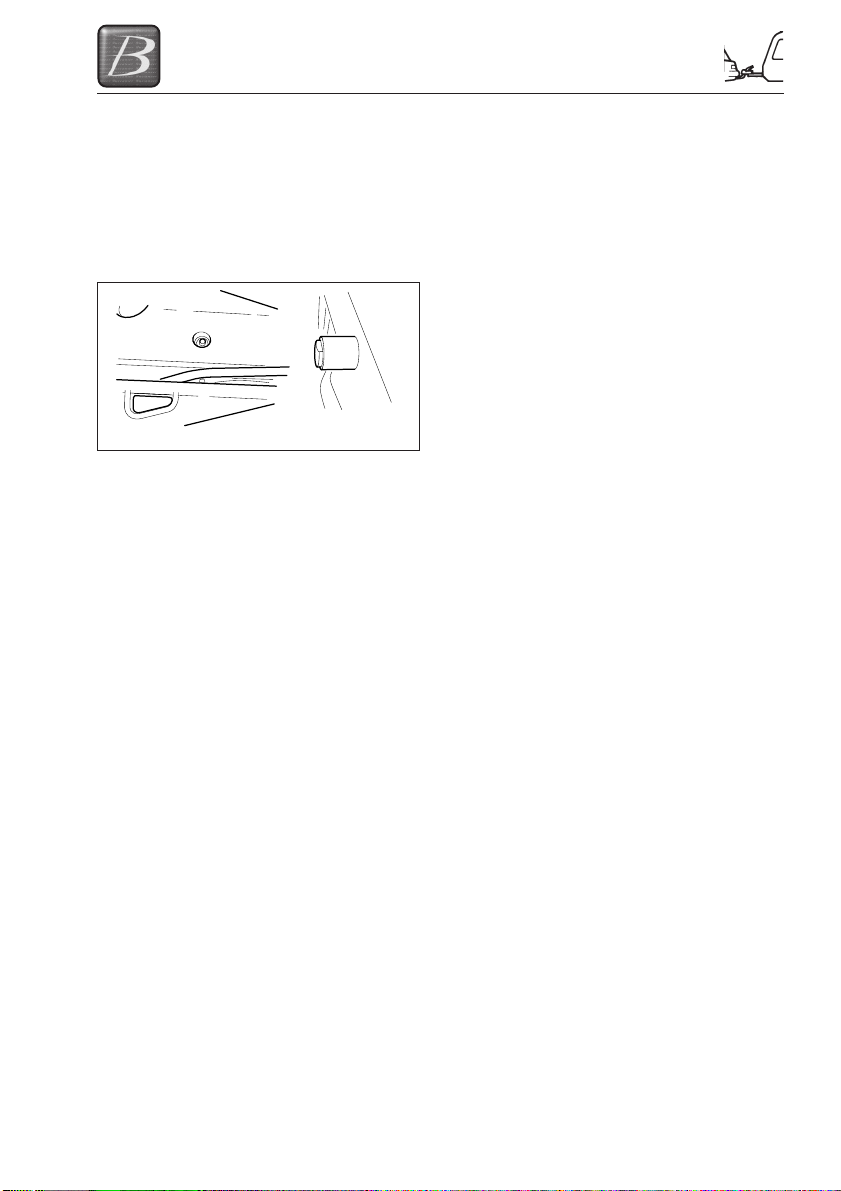
HANDBRAKE
Your caravan is fitted with BPW running gear
and handbrake. It is essential that prior to
towing you ensure that your handbrake is in
the fully off position. This can be confirmed
by ensuring that the handbrake arm is resting
on the blue stop fitted to the side of the A
frame as shown in Fig 3-7 below.
Fig 3-7
CABLES
For peace of mind, you may wish to check
the ability of the cables to be able to cope
with towing the vehicle at extreme angles
before setting off. To do so position the
vehicle at alternate extreme angles and
check that the cables do not pull too tight, are
liable to stretch or become unplugged. No
cables should be allowed to touch the ground
as they will wear and become damaged and
ineffective.
Please Note: If having followed this advice,
you feel you cannot achieve a satisfactory
cable arrangement, consult your caravan or
tow bar supplier or service agent.
3-5

PREPARING FOR THE ROAD
3-6
TOWING AND DRIVING
TOWING AND DRIVING
REVERSING
It is advisable to have a second person
assisting when reversing the caravan.
Start practising by choosing a left-hand bend
for ease. Reverse slowly; turning the wheel,
initially the opposite way to the direction you
want the caravan to go.
Now the front of the caravan is nudged out
and is moving the rear in the intended
direction. Take care not to hit the van with the
car!
Midways through the manoeuvre, when the
caravan is correctly angled, reduce speed to
a crawl and gradually apply opposite lock.
Make the car follow the caravan round then
finally straighten up.
Please note: Proficiency at reversing can
only be achieved with practice.
SPEED LIMITS
•Always adhere to the speed limits in
force.
• When national speed limits apply, when
towing on a single carriageway, the
speed limit is reduced to 50mph. Dual
carriageway and motorways, the speed
limit is reduced to 60mph.
SETTING OFF
(i) Pull away smoothly in the towing
vehicle. Allow more engine speed to
produce the power to move the
additional weight of the caravan.
(ii) Avoid wear and tear on the clutch and
transmission by taking extra care not to
‘ride’ the clutch.
(iii) Change gears smoothly. Try not to jerk
the clutch.
CARAVAN HANDLING
(i) Allow for the caravan being wider than
the car. Ensure you have a clear view
to the rear. This may require the fitting
of extended mirrors for towing your
caravan.
(ii) Give yourself more room when
cornering to ensure your caravan
wheels do not strike the kerb.
(iii) When passing other vehicles, allow
more than the normal clearance for
driving solo.
(iv) Allow longer to obtain a fast enough
speed to pass other vehicles.
(v) Allow for the vehicle being twice its
normal length. Do not suddenly swing
out.
(vi) Carry out all manoeuvres as smoothly
as possible.
(vii) Use the wing mirror to check the
caravan has clearly passed other road
users when overtaking and changing
lanes.
(viii) Adverse weather conditions may affect
the steering and braking characteristics
of your caravan.
Fig 4-1
4-1

TOWING AND DRIVING
4-2

ARRIVING ON SITE
ARRIVING ON SITE
CHECK SITE REGULATIONS
On arrival at a site, you should always check
the site regulations. This will help avoid any
unnecessary conflict with site management
and other site users.
WARNING: Care has to be taken to
prevent grounding when traversing ramps
or other ground obstacles.
SELECTING A PITCH
Carefully select where you wish to place your
caravan. The site should be as level as
possible, preferably not under or near trees,
well drained and away from possible boggy
areas. Consider how you will move the
caravan when it is time to leave the site. On
sloping ground it is better to pitch facing
downhill, especially during wet weather.
SIDE-TO-SIDE LEVELLING
A quick glance at your pitch should tell you if
you are likely to need side to side levelling
i.e. levelling across the axle. On uneven
ground lateral levelling is accomplished by
the use of a leveller jack or ramp and a spirit
level placed ‘across’ the caravan floor (not
supplied).
Leveller Jack
Place the leveller jack, folded flat, in front of
the wheel needed to be raised to level the
axle. Tow the caravan onto the leveller jack
and adjust the height until the spirit level
shows that the caravan is laterally level.
Ramp
(i) Reverse onto your pitch about 30cm
(12") further back than you wish to end
up.
(ii) Then place the levelling ramp in front of
the wheel that needs to be raised.
(iii) Place a spirit level parallel to the axle on
the A-frame or just inside the caravan
door.
It helps to have two people at this point. One
should drive the car very slowly forward
moving the caravan wheel up the ramp, and
the other should indicate when the spirit level
bubble is in the middle.
Whichever method you use, and once level:
(i) Apply the caravan handbrake and chock
the caravan wheel if necessary.
(ii) Lower the jockey wheel to ground level
before unhitching. (See index
uncoupling)
(iii) If necessary use a load spreader, such
as a big foot or alternative suitable
device.
You should then park your car, usually next to
the caravan furthest away from the door side.
Please note: On upward facing pitches
when the hydraulically damped drawbar of
the hitch becomes fully extended, it will be
necessary to compress the drawbar slightly
in order to achieve a clean’ unhitching. With
the caravan brake on, reverse the towing
vehicle about 2.54cm (1") to release hitch
lock tension and using the jockey wheel
adjustment, unhitch the caravan as
previously described.
FRONT & BACK LEVELLING
This should be done only when the lateral
levelling is complete.
(i) Place the spirit level pointing front to
back just inside the caravan door or on
the A frame.
(ii) Then raise or lower the jockey wheel
until the caravan is horizontally level.
Please note: If there is a significant front to
back slope, you may need to place a block
under the jockey wheel.
(iii) Next, wind down the corner steadies
onto load spreaders (blocks of wood a
minimum of 15.25cm (6") square or ‘Big
Foot’ steady attachments) until they are
firmly set against the ground.
Please note: It is possible on very uneven
sites that when fully extended blocks may be
required under the corner steadies to achieve
this. It is important that the caravan is
correctly levelled to ensure the correct
working of the refrigerator, cooker etc.
(iv) Now that your caravan is level, place the
caravan step in front of the door
ensuring that it is stable and safe to use.
5-1

ARRIVING ON SITE
PARKING ON A REVERSE-SLOPING
SITE OR STEEP HILL
For successful parking on a reverse slope or
steep hill, the operator need only apply the
handbrake with one hand while gently but
purposely inching the caravan a small
distance backwards with the other.
CAUTION:
first
brace provided. Corner steadies should not
be used as a jack. Take care not to lift the
caravan wheels.
Never enter the caravan without
lowering the four corner steadies with the
5-2
GETTING STARTED
GETTING STARTED
You have arrived at your destination and now
want to start to enjoy your new Buccaneer
caravan. The following is a step by step
guide to connecting your services and getting
everything in your caravan working.
ELECTRICITY
Power Supply Charger
Your caravan is fitted with a power supply/
charger. This will charge the caravan battery
“not supplied” when fitted and also power the
12V systems in your caravan.
It is recommended that you always carry a
leisure battery.
The Charger is fully automatic and will not
overcharge the leisure battery.
12v Systems:
Your caravan is fitted with an automatic
system for selection of power.
When connected to the 230V site supply the
automatic Power Supply/Charger will charge
the leisure battery and the 12V systems.
When connected to the car (always
disconnect 230V supply), the system
automatically switches to the car supply.
When the towing vehicle’s engine is running
and the caravan’s 13 pin plug is connected,
the internal 12 volt power supply in the
caravan is turned off and all internal lights will
go out. The only 12 volt power left
operational within the caravan is the fridge
and the battery charger.
GENERATOR/CHARGER
When connecting to a generator, always
switch off the RCD (residual current device),
start the generator and allow running for a
few minutes to stabilise. When this has
happened, switch the RCD to the ON
position.
ELECTRICITY MAINS SUPPLY
Your caravan’s main electrical installation is
designed to run on 230V at 50 hertz AC
supply.
CONNECTING TO MAINS SUPPLY ON
ARRIVAL AT SITE
Before connecting the caravan installation to
the mains supply, check that:
(i) The mains supply is suitable for your
installation and appliances, i.e. whether
it is AC or DC and whether it is at the
correct voltage and frequency.
(ii) Your caravan is properly earthed. Never
accept a supply from a socket outlet or
plug having only two pins, or from a
lighting outlet.
(iii) Any residual current device (earth
leakage circuit breaker) in the mains
supply to the caravan has been tested
within the last month. In case of doubt,
consult the site owner or their agent.
(iv) Make sure that the switch at the site
supply point is off and that all electrical
equipment in the caravan is switched off
by ensuring your caravan mains
isolating switch on the MCB (miniature
circuit breaker) is in the ‘OFF’ position.
ELECTRICAL WARNING
Attention: Always disconnect the
electrical connector between the towing
vehicle and the caravan before
connecting a mains electric supply to the
caravan and before charging the caravan
battery by any other means.
Once the above checks have been made:
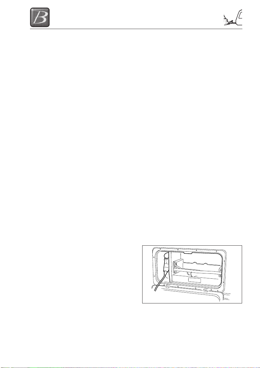
(v) Open the battery box on the nearside of
your caravan and insert the female
connector of the mains connection cable
supplied with your caravan into the inlet
within the battery box as shown below.
(vi) Locate the site supply and remove any
cover from the socket outlet provided at
the supply point. Insert the male plug at
the other end of the flexible orange
supply cable. Switch on the main switch
at the site supply point (if appropriate).
6-1
GETTING STARTED
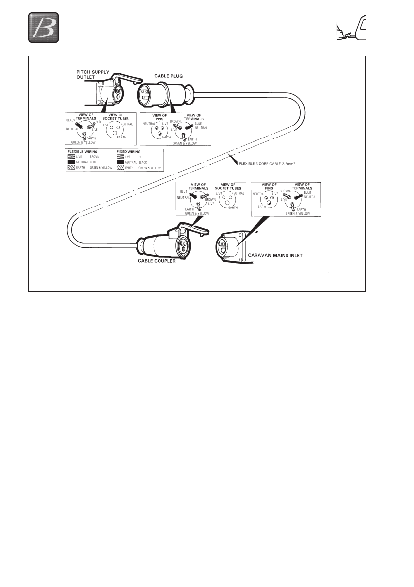
WIRING OF CONNECTING CABLE AND CARAVAN MAINS INLET
WARNING: It is essential that connections are made exactly as shown. If terminal
markings are not in accordance with the above diagram they must be ignored.
(vii) Place any surplus cable under the
caravan. Ensure that the surplus cable is
not coiled up as it could overheat.
(viii) Now switch on the mains isolating switch
within the caravan, this can be found on
the main consumer board, normally
located within the nearside front bed
box.
(ix) Check the RCD is working by pressing
the test button. Once pressed all
electrical lights and appliances should
cease to operate. Reset, and then check
the electrical system is operational.
(x) Finally in order to get your 12V system
operational, ensure the 12V switch
is in the ‘ON’ position. Refer to
index for further details on the control
panel fitted.
DISCONNECTING MAINS SUPPLY
WHEN LEAVING SITE
(i) Switch ‘OFF’ at the caravan mains
isolating switch.
(ii) Remove the male plug from the site
supply.
(iii) Disconnect the female plug from the
caravan and store the cable in an
appropriate locker.
OVERSEAS ELECTRICAL
CONNECTION
Please Note: Connection to a mains voltage
supply OVERSEAS requires particular
attention.
Care must be taken when connecting
supplies abroad since the supplies can be of
REVERSE POLARITY.
The significance of REVERSE POLARITY is
that when equipment is switched off, it may
not be electrically isolated. The only certain
way of making equipment safe is to unplug it.
A means of checking the polarity of the mains
supply when overseas is recommended.
There are available several proprietary
makes of equipment for the purpose.
If it can be achieved, it is preferable to
connect live to live, and neutral to neutral to
maintain full electrical protection.
CHECK all caravan equipment is set-up to
accept the site supply before actually
switching on.
6-2

GETTING STARTED
GAS SAFETY ADVICE
In the event of a suspected gas leak the gas
must be turned off using the isolation valve
on the gas bottle. A competent gas fitter
should then check the system before it is
used/reused.
Regularly check flexible gas hose, joints and
connections for tightness. Finally, make sure
that each gas appliance is working efficiently
to the recommendations of the appliance
manufacturers.
See Index - Ventilation
FACTS ABOUT LPG
• LPG is not poisonous.
•Bi-products are harmless.
• LPG is dangerous if all air and oxygen is
excluded.
• LPG has been given a smell by the
manufacturers in order to identify leaks.
• The gas is heavier than air and therefore
sinks to the lowest point.
AWNING SPACES, LPG AND
APPLIANCE EXHAUST
There is no danger of pollution of an
enclosed awning space from the LPG
exhaust from a refrigerator venting into it.
Space heaters may produce sufficient
exhaust to pollute the awning space, if it is
totally enclosed, from a general comfort,
smell and hygiene point of view. In extreme
cases there could be a build up of carbon
dioxide to a dangerous level. Caravan
owners are advised to allow some fresh air
circulation in the awning space when such
appliances are in use.
Please note: Ventilation holes must be clear
at all times.
LPG GAS SYSTEM
Buccaneer do not recommend the use of any
external cylinders. All cylinders in use should
be within the gas locker provided. If you wish
to utilise a larger cylinder and have this
outside the gas locker then the connecting
hose must not exceed 750mm.
It is recommended that no flammable
material is stored or placed within 300mm of
any open flame. You are advised not to use
any additional gas appliances outside your
caravan.
Please ensure that you have read the
operating instructions for each gas appliance
contained in your Owners Information Pack.
Please ensure that any gas hose left
unconnected is protected from dirt or other
foreign bodies entering the hose.
WARNINGS
• Fresh air circulation should be
allowed below the caravan when
appliances are in use and when flues
terminate below the floor to allow free
evacuation of the products of
combustion. At least three sides of
the underfloor space should always
be kept open and unobstructed
especially by snow. Do not make any
additional openings in the floor.
• Outlet sockets located within the
caravan should only be used with a
dedicated appliance and not an
independent unit.
• No appliance shall be used outside
when connected to an internal outlet.
• Maintain adequate spacing of
combustible materials from sources
of heat.
• Do not use additional independent
gas appliances inside the caravan.
GAS SUPPLY
Your caravan is designed to operate using
either propane or butane liquefied petroleum
gas at 30M/bar. Gas can be obtained from
your caravan dealer. Your caravan is
designed to accept a maximum 2 x 6kg BP
Light gas bottles.
Connection
Make sure that heating and cooking
appliances and gas cylinders are switched
off.
Each gas appliance is connected to its own
gas isolation tap under the cooker. These are
identified on the tap via a label. Below is a
key to identify each label.
To operate the tap the arrow on the tap
shows the direction of flow for the gas. The
6-3
GETTING STARTED
arrow should be pointing towards the
appliance for the appliance to operate. There
will be a small label next to the bank of taps
under the cooker, which is also reproduced
below:
Changing a Gas Cylinder
Before commencing to change a gas cylinder
ensure that the valve on the cylinder is turned
fully off. Turn off all gas operated appliances.
Remove the gas hose from gas cylinder.
Water Heater
Space Heater
Refrigerator
Cooking Appliance
Hob
Gas On/Off
Before refitting a gas cylinder, ensure that all gas
operated appliances are turned off - particularly
after winterisation. Ensure all connections are
secure.
When the cylinder is connected please ensure
that the high
pressure hose is not placed under
any strain.
WARNING: If cylinders other than those
recommended are used, ensure that the
cylinders are adequately supported, do not
block ventilation openings and cannot
cause damage to fixtures and fittings
located in the compartment.
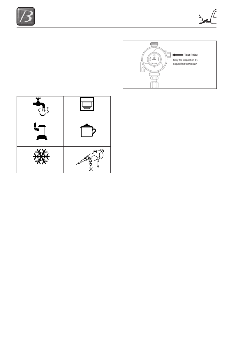
Gas Regulator
Your new Buccaneer caravan has been fitted
with a fully approved gas regulator designed
to operate at a gas pressure of 30Mbar. Your
regulator is fitted with a test point, which is
accessed via the inlet at the side of the
regulator. This access point is only for carrying
out gas pressure tests and should not be used
for any other purpose.
CAUTION: It is strongly recommended that
only Gas Safe Register™ approved gas fitters
carry out any work on your caravan gas
installation.
High Pressure Gas Hoses
You should only connect to this regulator
using a length of approved high-pressure
hose not exceeding 450mm from the gas
cylinder to the regulator. These approved
high-pressure hoses are available from your
Buccaneer Retailer. These hoses are
connected using screw thread fittings, which
will make a seal if connected and tightened
using a spanner. Once the hose is securely
connected turn on the gas tap above the
regulator, then turn on the gas bottle to allow
gas to flow into the caravan.
In order to make all your caravan gas
appliances operational it is necessary to open
each appliance gas tap as detailed in previous
column. All your gas appliances should now
be operational. Instructions on how to use
each appliance are detailed later in your
handbook.
WARNING: Aerosols and highly flammable
liquids must not be stored in the
compartment behind, or adjacent to, any
gas appliance. Some industrial LPG
appliances operate at high pressure and
require a ‘high pressure’ regulator. This
often has an adjusting handle on it. NEVER
use such a regulator on a caravan.
Ventilation holes must be clear at all times.
6-4
GETTING STARTED
WATER SYSTEM
Your new Buccaneer Caravan is fitted with an on board dual water pump system.
When the system is first used or if air is sucked into the system when emptying your water
container:
1. Insert plug into wall socket and close lid to lock plug in place.
2. Place carbon filter which is fitted to the hose into the water container.
3. Insert plug into wall socket and close lid to Switch on the 12V supply to pump.
4. Open the farthest away hot water tap from the pump.
5. When the water is flowing smoothly close hot tap and open the cold tap to expel the
remaining air.
• Repeat points 4 and 5 for the second farthest away tap from the pump, until the closest tap is
finally purged of air.
Note: Following these instructions will maximise the performance of your pump.
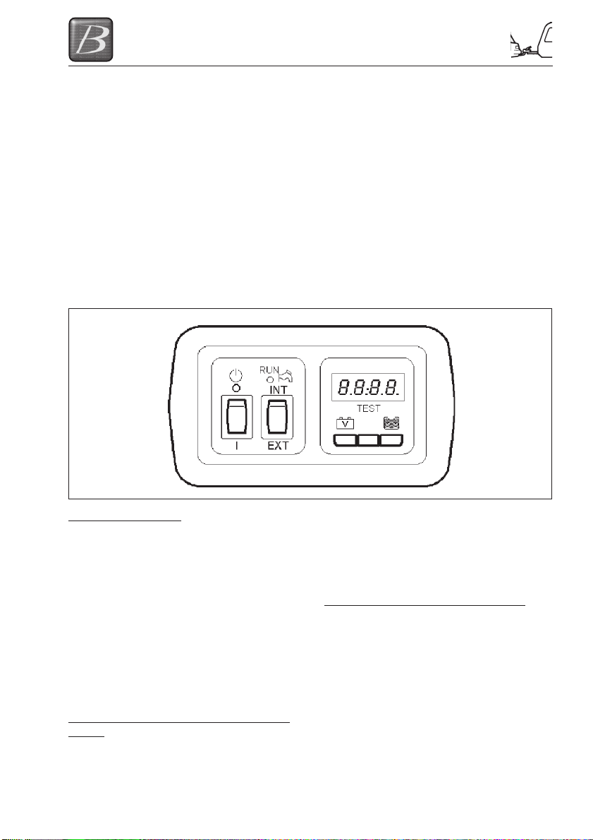
Water system control panel
Filling your water tank:
Ensure all the taps are in the closed position
and master pump switch is in the off position,
and the pump selection switch is in the EXT
position. Then connect your external water
container to the water inlet using the
connection hose supplied. Then place the
master pump switch to the ON position and
the pump will run and start to fill the water
tank from the external water container/supply.
When the tank is full the float switch fitted in
the tank will switch off the pump.
Note: This function is only for filling the
onboard water tank.
Using taps from an external water container/
supply:
Ensure all the taps are in the closed position
and master pump switch is in the off position,
and the pump selection switch is in the
CENTRE position. Then connect your
external water container to the water inlet
using the connection hose supplied. Then
place the master pump switch to the ON
position and the pump will run until the taps
are closed.
Using taps from the onboard water tank:
Ensure all the taps are in the closed position
and master pump switch is in the off position,
and the pump selection switch is in the INT
position. Then connect your external water
container to the water inlet using the
connection hose supplied. Then place the
master pump switch to the ON position and
the pump will run until the taps are closed.
6-5

GETTING STARTED
How to Use Your Aquasource
CAUTION: Do not under any circumstances
connect your caravan to the mains water
supply without the pressure reducer fitted.
Damage will occur to the caravan’s water
system! Max. working inlet pressure: 7 bar.
Static pressure: approx. 0.8 - 1 bar
Connection to your water inlet
(i) Uncoil the hose and screw tap adaptor
to the drinking water stand pipe and plug
in the hose adaptor.
(ii) Raise the lid; clean both the water
socket and the Aquasource plug. Push
the plug into the socket. Turn on the
mains water supply and check for leaks.
Open one of the taps and purge any air
that may be trapped in the water system.
To remove, pull the lower trigger and pull
out the hose plug.
Draining Down Your Water System
(i) It is essential that you drain down your
caravan water system when it is not in
use. This is most important during
winter months to protect against frost
damage.
(ii) Disconnect the water pump and switch
off power supply.
(iii) Remove the water heater fuse from the
switch spur and store in a safe place.
(iv) Open the safety drain valve on the water
heater located next to the water heater.
(v) Open all taps and remove all plugs from
sinks and showers. Lever operated taps
should have the lever put into the up and
central position.
(vi) Open the drain outlets on the outside of
your caravan.
(vii) Ensure the drain tap on your water tank
is in the open position.
(viii) Adjust the level of the caravan to ensure
that the drain outlet is at the lowest point
of the caravan. This will aid the flow of
water to ensure all water is drained off.
(ix) After 30 minutes level the caravan and
prepare it for storage if necessary.
6-6

ELECTRICAL SYSTEM
ELECTRICAL SYSTEM
12v POWER SUPPLY
Battery Installation
Your caravan will be fitted with a BCA Leisure
charging and power distribution unit.
If you wish to install a leisure battery please
ensure that it is placed on the battery tray
supplied with your caravan. Then place the
tray in the battery locker fitted to the side of
your caravan. Connect the battery to the
clamp fittings connected to the connection
leads within the battery box.
The type of leisure battery you should utilise
will depend on how you wish to use your new
caravan. If you are going to only use your
caravan when it is connected to a mains
supply and do not have a motor mover fitted,
then any good standard leisure battery rated
at least 85 ampere-hours at 20 hour
discharge rate is sufficient. However, if you
are going to use your caravan without a
mains connection or have a motor mover
fitted, then an AGM type battery rated at least
85 ampere-hours at 20 hour discharge rate is
recommended.
Battery Maintenance
Your leisure battery should be maintained in
accordance with the manufacturer’s
instructions. For information on the automatic
charging system in your caravan please refer
to ‘Automatic Charging System’ in the index.
Do not charge your leisure battery with any
charger other than that supplied. Failure to
comply may cause damage to your battery. If
you remove your leisure battery, ensure that
it is not placed on a cold surface as the
battery will deteriorate more rapidly than if
stored at a suitable temperature
Generators / Charger
All electrical equipment fitted in your new
caravan can be run from either a controlled
generator or charger whose output is
maintained between 11volts and 14volts.
At least once every 3 years, the caravan
electrical installation should be inspected and
tested, and a report on its condition obtained,
as prescribed in British Standard BS7671.
230v POWER SUPPLY
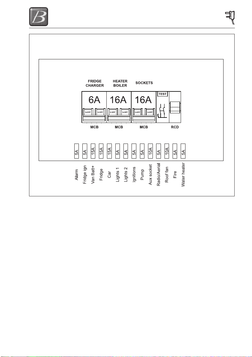
Mains Unit
The Mains Unit replaces the conventional
fuse box. Similar, but larger ones are often
fitted in new houses. The unit, normally
located in the wardrobe, gives overloads and
earth leakage protection for the 230V
electrical supply in your caravan.
For normal operation all switches on the unit
need to be in the ON position. The switches
on the left of the unit are known as MCB’s
(miniature circuit breakers). These take the
place of the conventional fuse but are more
convenient. In the event of a fault the MCB
‘trips’ i.e. automatically moves to the OFF
position. After elimination of the fault the
MCB can be re-set by switching to the ON
position (against the spring pressure in an
upwards direction). If an earth fault develops,
or a person was to touch a live piece of
equipment, the leakage of current to earth
should immediately operate the RCD
(residual current device) and ‘trip’ the main
switch, to the OFF position. This switch can
only be re-set after elimination of the fault.
Please Note: In case of difficulty, consult an
approved electrical installation contractor
(who may be the local electricity board). It is
dangerous to attempt modifications and
additions yourself. Lamp holder-plugs
(bayonet- cap adaptors) should not be used
under any circumstances.
Resetting the RCD
To re-set, operate the switch as for MCB’s.
Periodically, the RCD should be checked by
operating the test button marked ‘T’. The unit
should immediately switch to the OFF
position. If the unit does not switch off then a
qualified electrician should be consulted. If
the unit does switch off, the test is complete
and the switch can be re-set restoring the
supply back to normal.
Please note: Simultaneous operation of all
of the 230V mains electrical equipment may
not be possible. A typical UK caravan site
mains hook-up point provides a maximum
output of 10 amps and on some continental
sites the available output may be as low as 5
amps. If your loading exceeds the site supply
7-1

ELECTRICAL SYSTEM
it may trip the site circuit breaker. Please
check the available mains output with your
site operator. The following items need to be
added together if used simultaneously.
230V mains equipment typical consumption
figures:
• Refrigerator ............................... 0.50 amps
• Charger ..................................... 0.50 amps
• Water heater ............................... 3.9 amps
• Colour TV .................................. 3.33 amps
• Microwave ................................. 4.00 amps
• Air conditioning ......................... 4.00 amps
AUTOMATIC CHARGING SYSTEM
The battery charger will operate automatically
when the caravan is connected to the mains
outlet on a caravan site. The 12V system,
with the exception of the 12V refrigerator and
battery charging, will not operate when the
caravan is connected to the towing vehicle.
CHECK all caravan equipment is set-up to
accept the site supply before actually
switching on.
MAXIMUM BULB RATINGS FOR
INTERNAL LIGHTS
Type of Light Maximum Bulb Rating
Front locker light ............................. 20 watts
Downlighters .................................. 1.2 watts
Reading lights ................................ 1.2 watts
Floor LED ..................................... 0.36 watts
Under locker strip lights 300mm .... 1.2 watts
Under locker strip lights 600mm .... 2.2 watts
Awning lights ................................... 10 watts
Please note: Ensure that you only replace a
blown bulb with one of the same rating.
Never replace a bulb with one with a higher
rating. You should ensure that when fitted, no
bulb is in contact with the surface of the lamp
or shade.
Note: All LED lights can only be replaced
with a new complete unit and not a
replacement bulb.
CAUTION: Do not look directly at LED lights.
7-2
ELECTRICAL SYSTEM
MAINS UNITMAINS UNIT
MAINS UNIT
MAINS UNITMAINS UNIT
7-3
 Loading...