

elddis AUTOQUEST 2019 Handbook

AUTOQUEST
Campervan
OWNERS
HANDBOOK
Issue 1

CONTENTS
WELCOME & INTRODUCTION ............. 1-1
End Of Life Vehicle Directive .................. 1-1
Elddis Technical Approvals...................... 1-2
GENERAL SAFETY ............................... 2-1
Please read before using your
new Campervan. ..................................... 2-1
Proper And Safe Use Of Storage
Areas In Campervans ............................. 2-1
Ventilation ............................................... 2-2
High-Level Ventilation ............................. 2-2
Low-Level Ventilation .............................. 2-2
Ventilation in Separate Bedrooms........... 2-2
Gas Dispersal Holes ............................... 2-2
Fire Safety ............................................... 2-2
Fire Extinguishers ................................... 2-2
In Case Of Fire ........................................ 2-2
Fire Retardant Foams ............................. 2-2
PREPARING FOR THE ROAD............... 3-1
Campervan Weights Explained ............... 3-1
Mass in Running Order ........................... 3-1
Maximum Technically Permissible
Laden Mass ............................................ 3-1
User Payload .......................................... 3-1
Loading ................................................... 3-1
Before Moving Off ................................... 3-1
Pulling Off................................................ 3-2
Bicycle Racks .......................................... 3-2
MOTORWAY HANDLING ....................... 4-1
Best Practice ........................................... 4-1
Speed Limits ........................................... 4-1
Towing Your Campervan ......................... 4-1
ARRIVING ON SITE ............................... 5-1
Check Site Regulations ........................... 5-1
Selecting A Pitch ..................................... 5-1
Lateral Levelling (Side To Side) .............. 5-1
Leveller Jack ........................................... 5-1
Ramp ...................................................... 5-1
GETTING STARTED .............................. 6-1
Electricity ................................................. 6-1
Power Supply Charger ............................ 6-1
12v Systems: .......................................... 6-1
Generator/Charger .................................. 6-1
Electricity Mains Supply .......................... 6-1
Connecting To Mains Supply On
Arrival at Site ........................................... 6-1
Disconnecting Mains Supply When
Leaving Site ............................................ 6-2
Overseas Electrical Connection .............. 6-2
Gas Supply ............................................. 6-3
Connection .............................................. 6-3
Gas Regulator ......................................... 6-3
Gas Operation ......................................... 6-4
Water System.......................................... 6-4
Filling your Fresh Water Tank ................. 6-4
Waste Water Tank ................................... 6-4
Draining Down Your Water System ......... 6-4
GAS SAFETY ADVICE........................... 7-1
Facts about LPG ..................................... 7-1
Awning Spaces, LPG and Appliance
Exhaust ................................................... 7-1
LPG Gas System .................................... 7-1
Guidelines for the Safe Refuelling of
Autogas Vehicles .................................... 7-2
ELECTRICAL SYSTEM .......................... 8-1
Battery Installation .................................. 8-1
Battery Maintenance ............................... 8-1
Generators / Charger .............................. 8-1
230v Power Supply ................................. 8-1
Mains Unit ............................................... 8-1
Resetting the RCD .................................. 8-2
Automatic Charging System ................... 8-2
Maximum Bulb Ratings for Internal Lights8-2
HOW TO USE YOUR CAMPERVAN’S
EQUIPMENT ........................................... 9-1
Control Panel .......................................... 9-2
Vegas Button Control Panel .................... 9-2
Vegas Voltmeter without Water or
Gas Level ................................................ 9-3
Oven, Hob and Grill ................................ 9-4
Safety ...................................................... 9-4
Main Components ................................... 9-5
Before Use .............................................. 9-5
Use of the Burners .................................. 9-6
Use of the Electric Hotplate (if applicable)9-6
Use of the Grill ........................................ 9-7
Use of the Oven ...................................... 9-7
Safe Cooking .......................................... 9-8
Gas Leaks ............................................... 9-9
Temperature Control ............................... 9-9
Putting in Storage ................................. 9-10
Troubleshooting .................................... 9-10
Main Components ................................. 9-12
Switching on the Refrigerator ................ 9-12
Selecting Cooling Level ........................ 9-12
Selecting Night Mode ............................ 9-13
Use of the Freezer Compartment ......... 9-13
While Driving ......................................... 9-13
Switching off the Refrigerator ................ 9-14
Troubleshooting .................................... 9-14
CONTENTS-1
MY2019 Autoquest Campervan

CONTENTS
Microwave (When installed) .................. 9-15
Whale Heating System ......................... 9-16
Whale Space Heater - User Operation . 9-17
Whale Water Heater - User Operation .. 9-18
Whale Heating System -
Troubleshooting .................................... 9-19
Smoke Alarm ......................................... 9-22
Operation .............................................. 9-22
Nuisance Alarms ................................... 9-22
Maintenance ......................................... 9-22
Cleaning your Alarm.............................. 9-22
Carbon Monoxide Alarm ....................... 9-23
Recognising Alarm Signals and
Warnings ............................................... 9-23
Using your Alarm ................................... 9-23
Switching on your CO Alarm ................. 9-23
Re-setting the Alarm ............................. 9-23
Replacement of Batteries ...................... 9-23
Carbon Monoxide Alarm Procedure ...... 9-24
Maintenance of your Alarm ................... 9-24
Rooflights .............................................. 9-25
Standard MPK Rooflight ....................... 9-25
Midi Heki Rooflight ................................ 9-25
Door Flyscreen ...................................... 9-25
Taps ...................................................... 9-26
Kitchen Taps.......................................... 9-26
Internal Doors ....................................... 9-27
Toilet / Washroom Doors ....................... 9-27
Other Internal Doors ............................. 9-27
Magnetic Catches ................................. 9-27
Locker Door Catches (Paddle Latch) .... 9-27
THETFORD C-260 CASSETTE
TOILET RANGE ................................... 9-28
Introduction ........................................... 9-28
Preparing for Use (standard) ................ 9-28
Using the Toilet (standard) .................... 9-28
Emptying ............................................... 9-30
Emptying with Optional Features .......... 9-30
Cleaning and Maintenance ................... 9-31
Toilet Bowl ............................................. 9-31
Waste Holding Tank .............................. 9-31
Cleaning and Maintenance for Optional
Features ................................................ 9-32
Winter Operation ................................... 9-32
Storage ................................................. 9-32
Toilet Unit Malfunctions ......................... 9-32
Wing Omni-directional TV Antenna ....... 9-34
Operating Instructions ........................... 9-34
Changing the slant of the Antenna ........ 9-34
Wiring connections ................................ 9-34
Thule Step ............................................. 9-35
Operation .............................................. 9-35
Safety instructions ................................. 9-35
Maintenance ......................................... 9-35
How To Make Up Your Beds ................. 9-36
SECURITY ............................................ 10-1
Tracker (Option) .................................... 10-1
Campervan Theft .................................. 10-1
CARE OF YOUR CAMPERVAN ........... 11-1
Exterior Body Shell ................................ 11-1
Acrylic Windows .....................................11-1
Window Blinds & Flyscreens .................. 11-1
ABS - Components ................................ 11-1
Interior Walls .......................................... 11-1
Furniture ................................................. 11-1
Carpets, Upholstery And Curtains.......... 11-1
Washroom And Handbasin Fittings ........11-1
Shower Trays ......................................... 11-2
Water Systems ....................................... 11-2
Water Containers ................................... 11-2
Internal Water Systems .......................... 11-2
Thetford Toilet ........................................ 11-3
Changing a Wheel ................................. 11-3
Pre-season Water System Preparation.. 11-4
Getting Ready for the Winter ................. 11-5
STORAGE ............................................ 12-1
Long Term & Winter Storage ................. 12-1
Campervan Covers ............................... 12-1
Battery Maintenance ............................. 12-1
CAMPERVAN WARRANTY COVER ... 13-1
Non Warranty Repairs........................... 13-3
Remedial Work...................................... 13-3
CAMPERVAN CONSTRUCTION -
MAIN COMPONENTS .......................... 14-1
Windows ............................................... 14-1
Insulation ............................................... 14-1
EQUIPMENT LIST ................................ 15-1
Campervan ........................................... 15-1
ELECTRICAL DRAWINGS................... 16-1
Campervan ........................................... 16-1
GENERAL QUESTIONS ...................... 17-1
GLOSSARY .......................................... 18-1
CAMPERVAN ANNUAL SERVICE
RECORD .............................................. 19-1
Annual Habitation Service Records ...... 19-4
CONTENTS-2

CONTENTS
NOTIFICATION OF CHANGE OF
OWNERSHIP ........................................ 20-1
NOTIFICATION OF CHANGE TO
NAME AND ADDRESS ........................ 21-1
INDEX ................................................... 22-1
CONTENTS-3

CONTENTS
CONTENTS-4

INTRODUCTION
WELCOME & INTRODUCTION
Thank you for selecting your new campervan.
Before you drive off, please familiarise
yourself with the campervan and read this
owners’ handbook. This will help you to
obtain the maximum pleasure from your
vehicle and avoid endangering yourself and
others, refer to the Fiat user handbook
supplied with your campervan.
Additional information and detailed appliance
instruction manuals are also contained in
your Owner’s Information Pack.
Your new campervan has been designed
as a recreational vehicle and is intended
for recreational use only. It is not intended
for business use or for permanent
habitation. Elddis accepts no liability if
the campervan is used for any purpose
other than recreational/holiday use. Any
use other than recreational/holiday use
will invalidate your warranty.
Please note: All Elddis campervans are
classified as Grade 3 and therefore meet with
the thermal insulation and heat levels for
specific climatic conditions as specified within
the British and European Standard BS EN
1646 part 1.
By following the instructions provided in this
handbook and maintaining your campervan
in a first class roadworthy condition, you are
sure to have many years of carefree use. To
ensure the very best quality and reliability all
campervan designs and new developments
are rigorously tested. Therefore Elddis will
accept no liability or uphold the warranty if
the campervan is altered or modified in any
way.
IMPORTANT
The serial number of your campervan must
be quoted in all correspondence, it can be
found on a plate fixed next to the chassis
plate within the engine compartment. Your
campervan serial number can also be found
on the NCC certificate that can be found
within your Owner’s Information Pack.
There is also a Fiat serial number on the
chassis cab windscreen, which should be
quoted in any communications with Fiat.
Changing market and supply situations may
prevent us from maintaining the exact
specification details in this guide and we
therefore reserve the right to alter
specifications as materials and conditions
demand and if necessary supply an
alternative.
Enjoy your new campervan.
IMPORTANT: Register your vehicle with
us
In order to fully protect your valuable
purchase, we would kindly ask you to take
a few moments to complete our online
Warranty Registration.
Registering your vehicle will ensure that we
always have the most accurate and up-todate contact information and all of your
vehicle details to hand, should you ever need
our assistance.
Your feedback is incredibly important to us
and helps shape the future of our leisure
vehicles. We would be delighted if you would
also complete our accompanying online
Customer Questionnaire.
Both our Warranty Registration form and
our Customer Questionnaire can be found
on our Homepage: www.elddis.co.uk
End Of Life Vehicle Directive
Your new campervan fully complies with the
European Directive on the End of Life
Vehicles. In order to obtain information on
how to dispose of your campervan at the end
of its life please visit the Fiat website. The
Fiat website contains full details on all Fiat
products together with details of their
environmental and recycling policies. The site
address is www.fiat.co.uk.
1-1

INTRODUCTION
Elddis Technical Approvals
All Elddis campervans have been European
Commission Whole Vehicle Type approved.
In order to ensure your new campervan is
safe to use Elddis are members of and have
been inspected by the following bodies.
NCC who operate a certification scheme to
ensure compliance with the European safety
standards for campervans. National
Inspection Council for Electrical Installation
and Contracting (NICEIC) who carry out an
annual inspection of the Elddis electrical
installations within campervans.
Elddis is an ISO 9001:2015 approved
manufacturer certified by SGS Limited.
Please note: Elddis campervan model year.
Elddis model year starts on the 1st
September and runs to the 31st of August.
1-2

GENERAL SAFETY
GENERAL SAFETY
Please read before using your new
campervan.
In order for you to get the most out of your new
campervan it is necessary for you to be aware
of the following:
(i) Do not obstruct ventilators (See Safety
Section - Ventilation)
(ii) Inspect the flexible gas hose regularly
for deterioration and renew as
necessary, with approved type, as and
in any case no later than the expiry date
stated on the hose.
(iii) It is recommended that you provide a
dry powder fire extinguisher complying
with ISO 7165 of at least 1 KG capacity
by the exit door and a fire blanket next
to the cooker. Ensure you read the
‘advice to occupier label’ fitted to your
campervan.
(iv) Never use portable cooking or heating
equipment inside your campervan. Do
not use your fitted cooking equipment as
heating at any time.
(v) Never allow modification to your gas or
electrical system unless qualified
persons carry them out. A Gas Safe
Register™ approved gas fitter should
carry out all modification to the gas
system. Any modifications carried out on
the electrical system should be carried
out by an electrician on the roll of the
NICEIC or be a member of the ECA.
(vi) Never exceed your campervan’s
Maximum Technical Permissible Laden
Mass.
(vii) Never exceed the front or rear axle
maximum load as specified by the Fiat
weight plate under the bonnet.
(viii) Pull out worktop extensions, where
fitted, are only designed to take
maximum weight of 6kgs.
(ix) Please ensure extra care when young
children use high level bunks and
always use the safety nets and lift up
flaps provided.
(x) Do not leave children under 14 years of
age unattended in your campervan.
(xi) Please ensure all gas appliances are
turned off while you are travelling.
(xii) If you suspect there is a gas leak please
open all the windows then vacate the
campervan. Switch off the gas supply if
it is safe to do so. Then contact your
nearest Elddis Retailer to arrange for
them to check the gas system.
(xiii) Only those seats designated for
travelling should be occupied when the
campervan is in motion.
(xiv) Please note that campervans are
covered by the seat belt regulations,
which came into force in October 2006.
These require children that are under
12 years old and also under 135cm in
height to be seated in either child seats
or on bolster cushions.
(xv) Before travelling in your campervan:
Ensure all the tables have been stored
in their designated table storage
position.
(xvi) Ensure you remove all items from the
microwave before travelling.
(xvii) It is essential that you have securely
closed and locked the habitation door
before setting off on any journey.
(xviii) Care is to be taken when mounting and
dismounting the toilet due to its
elevated height.
Proper And Safe Use Of Storage
Areas In Campervans
The storage areas provided in your
campervan are designed solely for the
purpose of carrying personal possessions;
these areas must not be used:
• As a habitation area (e.g. living, sleeping
or cooking).
• To carry passengers, animals or livestock.
• For the installation (or use) of any LPG
gas operated appliances, (unless supplied
fitted by the manufacturer).
• For carrying LPG gas bottle cylinders,
(unless designated by the manufacturer).
• To carry any flammable liquids, (unless
properly stored, sealed and secured).
• For the operation of an electrical
generator.
• In such a way that the loading exceeds
the payload limit, as defined by the
manufacturer.
• Such that the weight distribution of the
vehicle means non-compliance with the
vehicle axle loads.
2-1

GENERAL SAFETY
VENTILATION
All campervans manufactured by Elddis are
ventilated at both high and low level in
accordance with BS EN 721 Safety
Ventilation. The fixed ventilation points fitted
in your campervan must not be blocked
under any circumstances as your safety may
depend upon them. It is advisable that the
fixed ventilation points are checked and
cleaned (where necessary) on a regular
basis.
High-Level Ventilation
This is always provided by fixed ventilation
within the fitted roof skylight. These roof
skylights should be cleaned annually by use
of a small brush to remove any dust that may
have accumulated around the mesh fitted.
On some roof skylights the mesh can be
easily removed to aid cleaning. On
fan-assisted roof skylights it is essential that
the fan is switched off prior to cleaning.
Low-Level Ventilation
All Elddis campervans have fixed low level
ventilation provided. These ventilators are
covered with plastic covers designed to
prevent them from being obstructed by items
placed within the bed box. These covers can
be removed by undoing the two screws in
order to facilitate cleaning the ventilators,
however these covers must be replaced once
cleaning is completed.
It is essential for your safety that these
ventilators are not blocked at any time.
Ventilation in Separate Bedrooms
In campervans with separated sleeping
areas, separate ventilation is required and is
provided via a roof skylight at high level and
a ventilator at low level within a bed box.
Gas Dispersal Holes
All appliances and gas unions have a gas
dispersal hole within the same compartment.
It is essential that these are not blocked or
made ineffective.
FIRE SAFETY
Fire Extinguishers
It is recommended that a 1 kg (2lb) minimum
capacity dry powder fire extinguisher be
carried inside your campervan at all times. A
pan fire must not have an extinguisher aimed
at it, but must be smothered with a fire
blanket.
In Case Of Fire
(i) Get everyone out of the campervan as
quickly as possible using whichever exit
is quickest including windows. Do not
stop to collect any personal items.
(ii) Raise the alarm. Call the fire brigade.
(iii) Turn off gas container valve if safe to do
so.
Fire Retardant Foams
All campervans are equipped with
Polyurethane (PU) foam which are
combustion modified foam cushions, sprung
mattresses and fire retardent fabric. All
furnishings and fabrics used by Elddis
comply with the Furniture and Furnishings
(Fire Safety) Regulations. In addition all
upholstery is made of fire retardant fabric.
2-2
PREPARING FOR THE ROAD
PREPARING FOR THE ROAD
Before venturing out on to the road with your
campervan, it is important that you prepare
correctly.
CAMPERVAN WEIGHTS EXPLAINED
Mass in Running Order
The weight of your campervan as it leaves
the factory, as new with standard fixtures and
fittings, plus an allowance for the driver of
75kgs, the mass of the fuel (diesel) when the
tank is 90% full and an allowance of 12kg for
a full gas tank.
Maximum Technically Permissible
Laden Mass
The maximum mass the vehicle can be when
fully laden for use on the road.
User Payload
The load margin (payload), this represents
the difference between the Mass in Running
Order and the Maximum Technically
Permissible Laden Mass. It shows the
maximum weight that can be loaded into your
campervan, covering items such as food,
crockery, cutlery, clothing, bedding, etc.
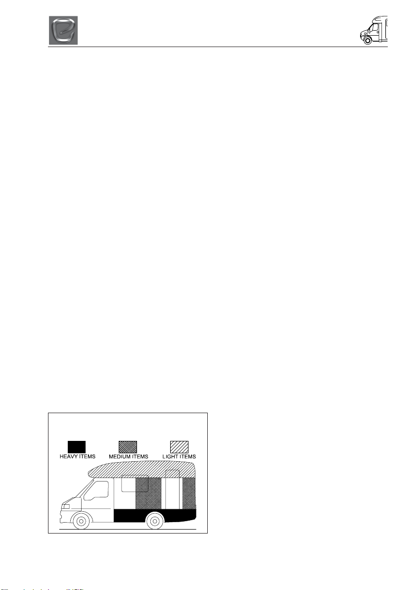
Loading
It should be noted that even weight
distribution is a major factor in making your
campervan an easy and pleasant vehicle to
drive. Care should therefore be taken in
balancing the load, ensuring that heavy
items are well spaced and are in as low a
position as possible, for example, low
cupboards and bed boxes.
SENSIBLE LOADING
HOW TO APPORTION WEIGHT
Note: Light items are considered as clothing
and bedding. It is not recommended to travel
with tinned items in overhead lockers.
IMPORTANT: Do not exceed maximum
technical permissible laden mass for your
campervan.
BEFORE MOVING OFF
Whenever making a journey with your
campervan, either setting off on holiday or
returning home, it is good practice to run
through this simple checklist.
(i) Close and secure all cupboards and
drawers and secure any loose articles.
(ii) Do not store tins, bottles, etc. in
overhead lockers.
(iii) Close and secure all windows and
roof lights.
(iv) Leave all curtains and blinds open to
aid visibility.
(v) Turn off all gas appliances.
(vi) Switch off 240volt supply at source;
disconnect mains cable and store in an
appropriate place.
(vii) Check that the battery is secure.
(viii) Ensure the fridge is on 12V operation
and door lock is set. (Note: the
electrical relays will allow the fridge to
be run on the vehicle battery when the
engine is running.)
(ix) Remove any external fresh water
connections etc.
(x) Make sure any heavy articles are
stored in accordance with the loading
procedure.
(xi) Lock the campervan habitation door.
(xii) Check your external rear view mirrors
and adjust if necessary.
(xiii) If a step is used, ensure it is put away
before moving off.
(xiv) Your new Elddis campervan has been
designed to carry passengers in
designated passenger seats only. The
fitting of a 3-point seat belt can identify
these seats. Any seat not fitted with a 3
point seat belt is not designated as a
passenger seat.
3-1

PREPARING FOR THE ROAD
(xv) Ensure all tables have been stored in
their designated table storage position.
(xvi) Ensure you remove all items from the
microwave (if fitted) before towing.
(xvii) Check all the road lights are
operational.
Pulling Off
• Pull away smoothly.
• Avoid wear and tear on clutch and
transmission by taking extra care.
• Change gears smoothly.
• Try not to jerk the clutch.
Bicycle Racks
Fitting a bicycle rack to the rear panel of a
campervan will affect how weight is
distributed. There are restraints to be aware
of with such fitments.
The maximum loading allowed on the back
panel is 35 kgs including the weight of the
bike rack and bicycles.
The campervan must also be balanced to
take into account the new weight distribution.
Weight must be distributed evenly.
Elddis cannot be held responsible for
problems related to a bicycle rack fitted by a
third party.
3-2

MOTORWAY HANDLING
MOTORWAY HANDLING
Best Practice
To gain the most enjoyment and ensure a
long life for your campervan, the following
should be observed:
• Do not bump kerbs with wheels.
• When overtaking ensure sufficient
clearance is given to other vehicles.
• Your campervan will not accelerate as
quickly as a car, so take this into account
when attempting to overtake other
vehicles.
• Carry out all manoeuvers as smoothly as
possible.
• Use the wing mirror to check your
campervan has cleared the other vehicle.
• Slow down and take care when driving
over raised speed bumps, ‘sleeping
policemen’ or when embarking/
disembarking ferries.
• In high or cross winds, travelling downhill
or in conditions of poor visibility reduce
your speed.
• High-sided vehicles can cause air
buffeting so extra care must be taken
when passing or being passed. Leave as
much space as possible when overtaking
these types of vehicles
Speed Limits
Be sure to observe all statutory speed limits
and adapt your speed to take account of
prevailing weather and road conditions.
Towing Your Campervan
In the unlikely event that you have to tow
your campervan, the towing point is fitted
within the front bumper, behind the
removable flap provided by Fiat. The towing
hook can be found in the tool box supplied by
Fiat, found under the front passenger seat.
4-1

MOTORWAY HANDLING
4-2
ARRIVING ON SITE
ARRIVING ON SITE
CHECK SITE REGULATIONS
On arrival at a campsite, you should always
check the site regulations. This will help avoid
any unnecessary conflict with site
management and other site users.
SELECTING A PITCH
Carefully select where you wish to place your
campervan. The site should be as level as
possible, preferably not under or near trees,
well drained and away from possible boggy
areas. Consider how you will move the
campervan when it is time to leave the site.
On sloping ground it is better to pitch facing
downhill, especially during wet weather.
LATERAL LEVELLING (SIDE TO SIDE)
A quick glance at your pitch should tell you if
you are likely to need side to side leveling i.e.
levelling across the axle. On uneven ground
lateral levelling is accomplished by the use of
a leveler jack or ramp and a spirit level
placed ‘across’ the campervan floor.
LEVELLER JACK
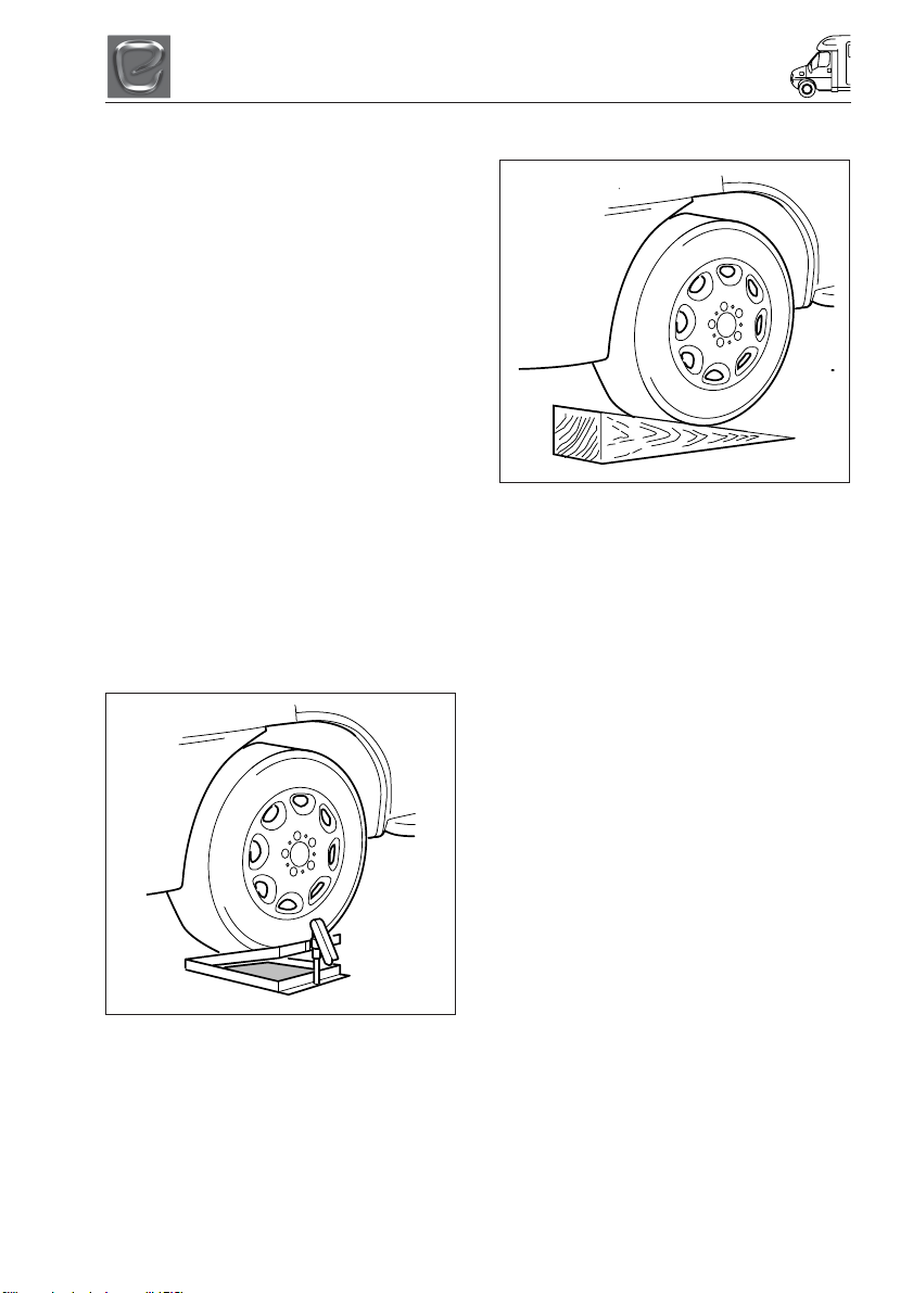
RAMP
Reverse onto your pitch about a foot further
back than you wish to end up. Then place the
levelling ramp in front of the wheel that needs
to be raised.
Place a spirit level parallel to the axle or just
inside the campervan door. It helps to have
two people at this point. One should drive the
campervan very slowly forward moving the
wheel up the ramp and the other should
indicate when the spirit level bubble is in the
middle.
Whichever method you use, once level, apply
the campervan handbrake and chock the
campervan wheel if necessary.
Place the leveller jack, folded flat, in front of
the wheel that is to be raised to level the
axle. Drive the campervan onto the leveler
jack and adjust the height until the spirit level
shows that the campervan is laterally level.
5-1

ARRIVING ON SITE
5-2
GETTING STARTED
GETTING STARTED
You have arrived at your destination and now
want to start to enjoy your new campervan.
The following is a step by step guide to
connecting your services and getting
everything in your campervan working.
ELECTRICITY
Power Supply Charger
Your campervan is fitted with a power supply/
charger. This will charge the leisure battery
“where supplied” when fitted and also power
the 12V systems in addition to your leisure
battery.
A leisure battery must be fitted to the
campervan at all times when in use.
The Charger is fully automatic and will not
overcharge the leisure battery.
12v Systems:
When connected to the 230V site supply the
automatic Power Supply/Charger will charge
the leisure battery and power the 12V
systems.
When the ignition is switched on the 12V
system in the campervan is automatically
switched off, vehicle power is supplied to the
refrigerator.
GENERATOR/CHARGER
When connecting to a generator, always
switch off the RCD, start the generator and
allow running for a few minutes to stabilise.
When this has happened, switch the RCD to
the ON position.
ELECTRICITY MAINS SUPPLY
Your campervan’s main electrical installation
is designed to run on 230V at 50 hertz AC
supply.
CONNECTING TO MAINS SUPPLY ON
ARRIVAL AT SITE
Before connecting the campervan installation
to the mains supply, check that:
(i) The mains supply is suitable for your
installation and appliances, i.e. whether
it is AC or DC and whether it is at the
correct voltage and frequency.
(ii) Your campervan is properly earthed.
Never accept a supply from a socket
outlet or plug having only two pins, or
from a lighting outlet.
(iii) Any residual current device (earth
leakage circuit breaker) in the mains
supply to the campervan has been
tested within the last month. In case of
doubt, consult the site owner or their
agent.
(iv) Make sure that the switch at the site
supply point is off and that all electrical
equipment in the campervan is switched
off by ensuring your campervan mains
isolating switch on the MCB is in the
‘OFF’ position.
Once the above checks have been made:
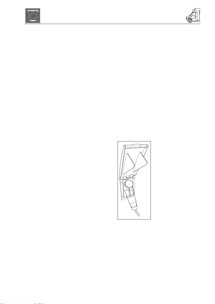
(v) Remove any cover to the electricity inlet
provided on the campervan and insert
the female connector of the flexible
orange supply cable as shown.
(vi) Locate the site
supply and remove any
cover from the socket
outlet provided at the
supply point. Insert the
male plug at the other
end of the flexible orange
supply cable. Switch on
the main switch at the site
supply point (if
appropriate).
(vii) Place any surplus
cable under the
campervan. Ensure that
the surplus cable is not
coiled up as it could
overheat.
(viii) The MCB main electricity supply switch
should be put in the ‘ON’ position.
(ix) Check the RCD is working by pressing
the test button. Once pressed all
electrical lights and appliances should
cease to operate. Reset and then check
the electrical system is operational.
6-1
GETTING STARTED
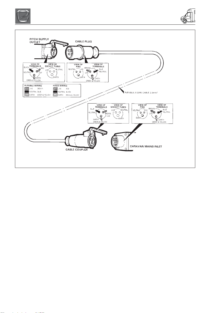
WIRING OF CONNECTING CABLE AND CAMPERVAN MAINS INLET
WARNING: It is essential that connections are made exactly as shown. If terminal
markings are not in accordance with the above diagram they must be ignored.
(vii) Place any surplus cable under the
campervan. Ensure that the surplus
cable is not coiled up as it could
overheat.
(viii) The MCB main electricity supply switch
should be put in the ‘ON’ position.
(ix) Check the RCD is working by pressing
the test button. Once pressed all
electrical lights and appliances should
cease to operate. Reset, and then check
the electrical system is operational.
(x) Finally in order to get your 12V system
operational, ensure the master 12V
switch is in the ‘ON’ position.
DISCONNECTING MAINS SUPPLY
WHEN LEAVING SITE
(i) Switch ‘OFF’ at the campervan mains
isolating switch.
(ii) Remove the male plug from the site
supply.
(iii) Disconnect the female plug from the
campervan and store the cable in an
appropriate locker.
OVERSEAS ELECTRICAL
CONNECTION
Please Note: Connection to a mains voltage
supply OVERSEAS requires particular
attention.
Care must be taken when connecting
supplies abroad since the supplies can be of
REVERSE POLARITY.
The significance of REVERSE POLARITY is
that when equipment is switched off, it may
not be electrically isolated. The only certain
way of making equipment safe is to unplug it.
A means of checking the polarity of the mains
supply when overseas is recommended.
There are available several proprietary
makes of equipment for the purpose.
If it can be achieved, it is preferable to
connect live to live and neutral to neutral to
maintain full electrical protection.
CHECK all campervan equipment is set-up to
accept the site supply before actually
switching on.
6-2
GETTING STARTED
GAS SUPPLY
Your campervan is designed to operate using
either propane or butane liquefied petroleum
gas at 30M/bar. Gas can be obtained from a
LPG filling station. To locate your nearest
station search www.mylpg.eu
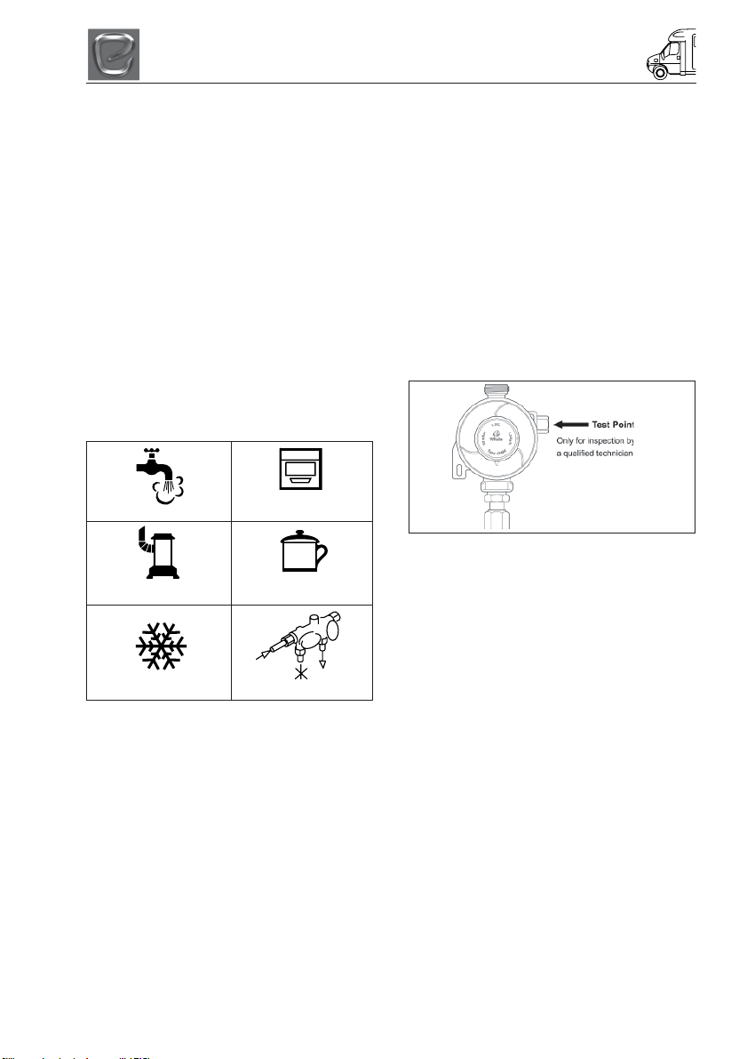
Connection
Make sure that heating and cooking
appliances and gas tank are switched off.
Each gas appliance is connected to its own
gas isolation valve which is adjacent to or
close proximity. These are identified on the
tap via a label. Below is a key to identify each
label.
To operate the tap the arrow on the tap
shows the direction of flow for the gas. The
arrow should be pointing towards the
appliance for the appliance to operate.
Water Heater
Space Heater
Cooking Appliance
Hob
Gas Regulator
Your new campervan has been fitted with a
fully approved gas regulator designed to
operate with Propane gas at a gas pressure
of 30mBar. Your regulator is fitted with a test
point, which is accessed via the inlet at the
side of the regulator. This access point is only
for carrying out gas pressure tests and must
not be used for any other purpose.
Please note: Only Gas Safe RegisterTM or
STGW approved gas fitters can carry out any
work on your campervan gas installation.
This regulator is not designed for vehicle in
motion.
Refrigerator
Gas On/Off
6-3

GETTING STARTED
Gas Operation
In order to make all your campervan gas
appliances operational it is necessary to
open each appliance gas tap as detailed on
the previous page. All your gas appliances
should now be operational. Instructions on
how to use each appliance are detailed later
in your handbook.
WARNING: Aerosols and highly flammable
liquids must not be stored in the
compartment behind, or adjacent to, any
gas appliance. Some industrial LPG
appliances operate at high pressure and
require a ‘high pressure’ regulator. This
often has an adjusting handle on it.
NEVER use such a regulator on a
campervan.
Ventilation holes must be clear at all
times.
WATER SYSTEM
Filling your fresh water tank
Your campervan is fitted with a standard
water inlet which can be filled using a hose
pipe connected to a tap placed into the water
filler point.
Please take care not to over fill your tank it is
advised that someone monitors the water
level in the tank while filling is in progress.
Waste Water Tank
Your new campervan is also fitted with a 45
litre waste water tank. All waste water
excluding the toilet waste will run into the
waste water tank. The level of water in the
tank can be monitored using the control
panel. Opening the grey waste outlet
provided on the outside of the campervan
empties the tank. Open the tap when the
outlet is over a drain and the water will run
out of the tank.
Draining Down Your Water System
(i) It is essential that you drain down your
campervan water system when it is not
in use. This is most important during
winter months to protect against frost
damage
(ii) Disconnect the water pump and switch
off power supply.
(iii) Open the safety drain valve on the water
heater located next to the water heater.
(iv) Open all taps and remove all plugs from
sinks and showers. Lever operated taps
should have the lever put into the up and
central position.
(v) Open both the blue and grey drain
outlets on the outside of your
campervan.
(vi) Adjust the level of the campervan to
ensure that the drain outlet is at the
lowest point of the campervan.
6-4

GAS SAFETY ADVICE
GAS SAFETY ADVICE
In the event of a suspected gas leak the gas
must be turned off using the isolation valve
on the LPG tank. A competent gas fitter
should then check the system before it is
used/reused.
Regularly check flexible gas hose, joints and
connections for tightness. Finally, make sure
that each gas appliance is working efficiently
to the recommendations of the appliance
manufacturers.
See Index - Ventilation
FACTS ABOUT LPG
• LPG is not poisonous.
• Bi-products of incomplete combustion
are harmful to health.
• LPG is dangerous if all air and oxygen is
excluded.
• LPG has been given a smell by the
manufacturers in order to identify leaks.
• The gas is heavier than air and therefore
sinks to the lowest point.
AWNING SPACES, LPG AND
APPLIANCE EXHAUST
Space and Water heaters may produce
sufficient amounts of CO2 to pollute the
awning space, if it is totally enclosed and
therefore MUST NOT BE used on gas when
an awning is attached.
In extreme cases there could be a build up of
carbon dioxide to a dangerous level.
Campervan owners are advised to allow
some fresh air circulation in the awning
space when such appliances are in use.
Please note: Ventilation holes must be clear
at all times.
LPG GAS SYSTEM
Elddis does not recommend the use of any
external cylinders.
It is recommended that no flammable
material is stored or placed within 300mm of
any open flame.
Please ensure that you have read the
operating instructions for each gas appliance
contained in your Owners Information Pack.
WARNINGS
• Fresh air circulation should be
allowed below the campervan when
appliances are in use and when flues
terminate below the floor to allow free
evacuation of the products of
combustion. At least three sides of
the underfloor space should always
be kept open and unobstructed
especially by snow. Do not make any
additional openings in the floor.
• No appliance shall be used outside
when connected to an internal outlet.
• Maintain adequate spacing of
combustible materials from sources
of heat.
• Do not use additional independent
gas appliances inside the campervan.
7-1

GAS SAFETY ADVICE
GUIDELINES FOR THE SAFE
REFUELLING OF AUTOGAS
VEHICLES
Health and Safety of Refuelling
The driver, when pulling up to the Autogas
dispenser, is to apply their handbrake and
switch off the engine.
No ignition sources should be present
including no smoking, no naked flames or
mobile phones.
General Filling Guidelines
For a complete guide to filling an LPG vehicle
with LPG please refer to appendices 1 and 2
of this guidance note.
Note: The vehicle’s LPG tank is fitted with an
automatic stop fill valve set at 80% of the
tanks volume, which should prevent the
vehicle from being overfilled. If an overfill
does occur, put the nozzle out of action and
call an engineer to inspect it. It is
recommended that the driver of the vehicle
should get their vehicle inspected by a
recognised LPG servicer.
Filling Nozzles
There are two types of filling nozzles
commonly used
• LG30 Gas Guard
• V10 DeVisser
TM
TM
Both types of filling nozzle use the Bayonet
type nozzle connection, which should connect
directly on to the vehicle filler point.
Adaptors and Portable LPG Cylinders
Adaptors are not recommended for use at
Autogas tanks. Calor also complies with the
UKLPG guidance and does not allow the
filling of owner used portable refillable LPG
cylinders at Autogas refuelling sites. A copy of
this guidance can be found on the UKLPG
website www.uklpg.org.
Safety Note: When filling the vehicle, you
must always ensure that the nozzle is
correctly fitted and clamped. This should stop
any possible product release due to a poor
connection seal.
First Aid
If any product is released and comes into
contact with you or the customer the
following first aid measures should be used:
Inhalation: Remove the affected person to
fresh air. Keep the patient warm and at rest.
If breathing has stopped administer artificial
respiration. Give external cariac massage if
necessary. If the person is breathing, but
unconscious, place them in the recovery
position. Obtain medical assistance
immediately.
Skin: Burns should be flushed with tepid
water to normalise temperature and until
circulation returns. Cover the burns with
sterile dressings. Do not apply ointments or
powders. Obtain medial assistance
immediately.
Eyes: Cold burns should be flushed
immediately with water at normal
temperature. Hold eyelids apart while
flushing to rinse entire surface of the eye and
lids with water. Cover the eye with a sterile
dressing and obtain medial assistance
immediately.
Filling Instructions
Always check that the nozzle is disconnected
from the vehicle and replaced in the
dispenser holder before the vehicle is driven
away.
Gas Guard
TM
nozzle filling instructions
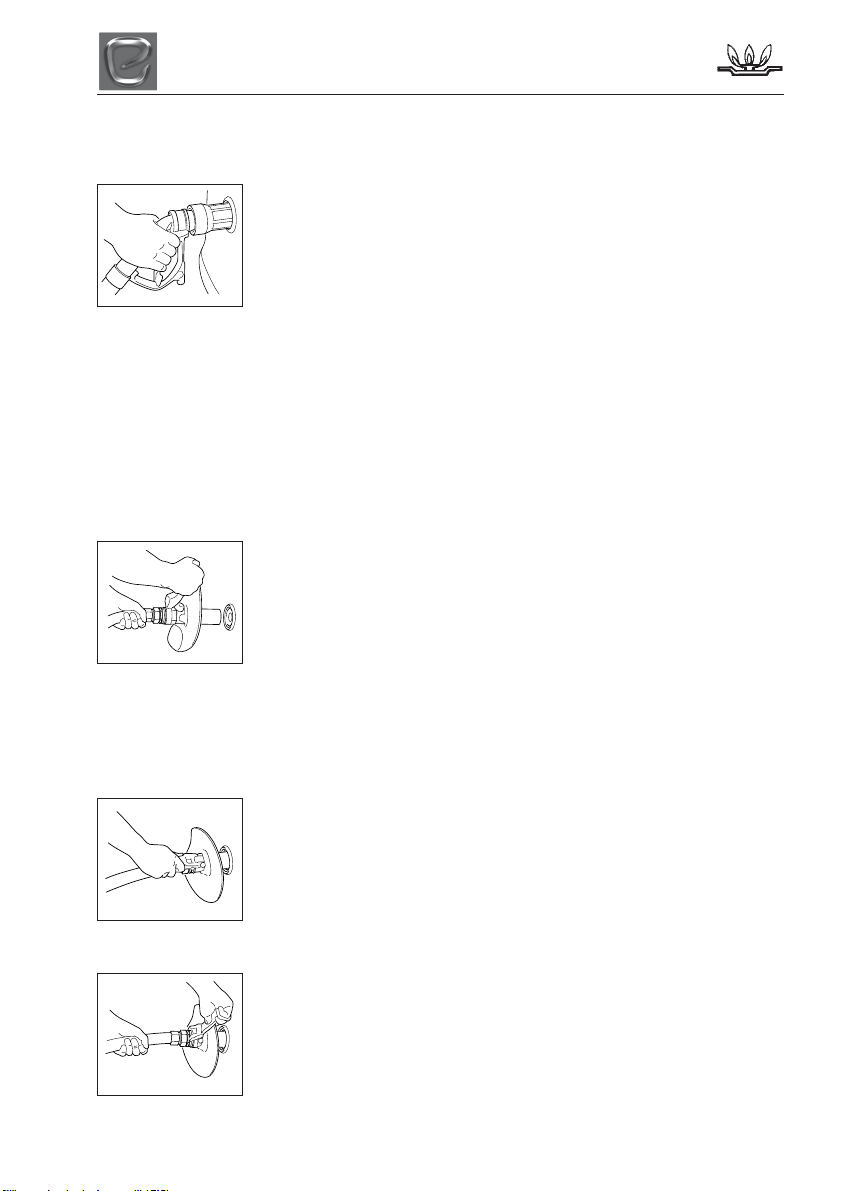
Connecting
1. Push nozzle over the
lugs on the filler valve
and turn barrel quarter
turn clockwise to lock.
Do not squeeze lever
before nozzle is
connected. From this
moment onwards ensure hands are away
from the nozzle.
2. Pull back lever and
latch into place. Ensure
lever is latched
securely.
Push the ‘FILL’ button
dispenser and hold until
the fill is complete or
desired amount reached.
7-2
GAS SAFETY ADVICE
Disconnecting
Ensure hands are away from the nozzle
barrel.
3. When dispensing has
ended, squeeze back
lever and release the
latch, then release the
lever fully. A small
release of gas will occur
as you release the
lever. This is normal! Do not place hands on
barrel until after the gas has released.
4. Turn the barrel anti-clockwise a quarter
turn to release nozzle from the vehicle.
Replace nozzle in holder on dispenser.
De Visser
Ensure De Visser
TM
nozzle filling instructions
TM
nozzles are fitted with
protective nozzle shields. Report to site staff
if missing.
Connecting
1. Hold the hose behind
the nozzle and the
guard, keeping lever
pushed forward with the
handle at the 12 o’clock
position.
Locate the nozzle over the lugs on the filler
valve and turn the lever quarter turn
clockwise to lock.
From this moment ensure hands are away
from the nozzle barrel.
2. Pull back lever
towards hose and latch
into place. Ensure lever
is latched securely.
Push button and hold
until the fill is completed
or desired amount
reached.
Disconnecting
Ensure hands are away
from the nozzle barrel.
3. Hold hose behind
guard and release lever
by pushing forward. (Do
not place hands on the
nozzle until after the
gas has been released.
A small release of gas will occur as you
release the lever. This is normal!
4. Turn lever anti-clockwise quarter turn to
release nozzle from vehicle. Replace nozzle
in holder on dispenser.
7-3

GAS SAFETY ADVICE
7-4

ELECTRICAL SYSTEM
ELECTRICAL SYSTEM
12V POWER SUPPLY
Battery Installation
Your campervan will be fitted with a charging
and power distribution unit.
When installing the leisure battery please
ensure that it is placed on the battery tray
supplied with your campervan. Then place
the tray in the battery locker fitted. Connect
the battery to the clamp fittings connected to
the connection leads within the battery box.
We recommend that you refer to the NCC
approved battery scheme, which can be
found at www.thencc.org.uk.
Battery Maintenance
Storage
Ensure that the leisure battery is fully
charged before placing the vehicle into
storage.
Check the battery state every month, if the
terminal voltage drops below 12.07V then recharging is necessary.
Charging should be carried out in a cool, dry
well ventilated area.
CAUTION: Your Thatcham alarm system is
powered by the leisure battery. Therefore it is
recommended that a battery is installed at all
times. Failure to do so could void your
insurance policy.
Do not place the battery onto cold surfaces
such as concrete as this will affect the
battery’s ability to charge.
Points to remember
• Prolonged discharge causes harmful
sulfation and may damage a battery.
• For peak performance never let a battery
sit discharged for long periods of time.
• Over discharged batteries are
permanently damaged and need to be
replaced.
Note: Do not over discharge the battery. One
of the most common causes of battery failure
is when the battery is discharged below the
recommended level of approximately 12.2v ref table. Discharging a battery below this
figure will cause permanent damage.
Overheating and gassing will occur when reconnected to the mains supply.
12 Volt Battery State of Charge
Good
OK
Warning
Damaged
Good: the battery is in good condition and not in
need of charging
OK: nothing to worry about but put the battery on
charge as soon as you can
Warning: get the battery on charge as soon as you
can. Leave it and the battery will be damaged,
possibly beyond repair
Damaged: Replace battery
12.7V 100%
12.5V 90%
12.42V 80%
12.32V 70%
12.20V 60%
12.06V 50%
11.9V 40%
11.75V 30%
11.58V 20%
11.31V 10%
10.5V 0%
Generators / Charger
All electrical equipment fitted in your new
campervan can be run from either a
controlled generator or charger whose output
is maintained between 11volts and 14volts.
At least once every 3 years, the campervan
electrical installation should be inspected and
tested and a report on its condition obtained,
as prescribed in British Standard BS7671.
230v POWER SUPPLY
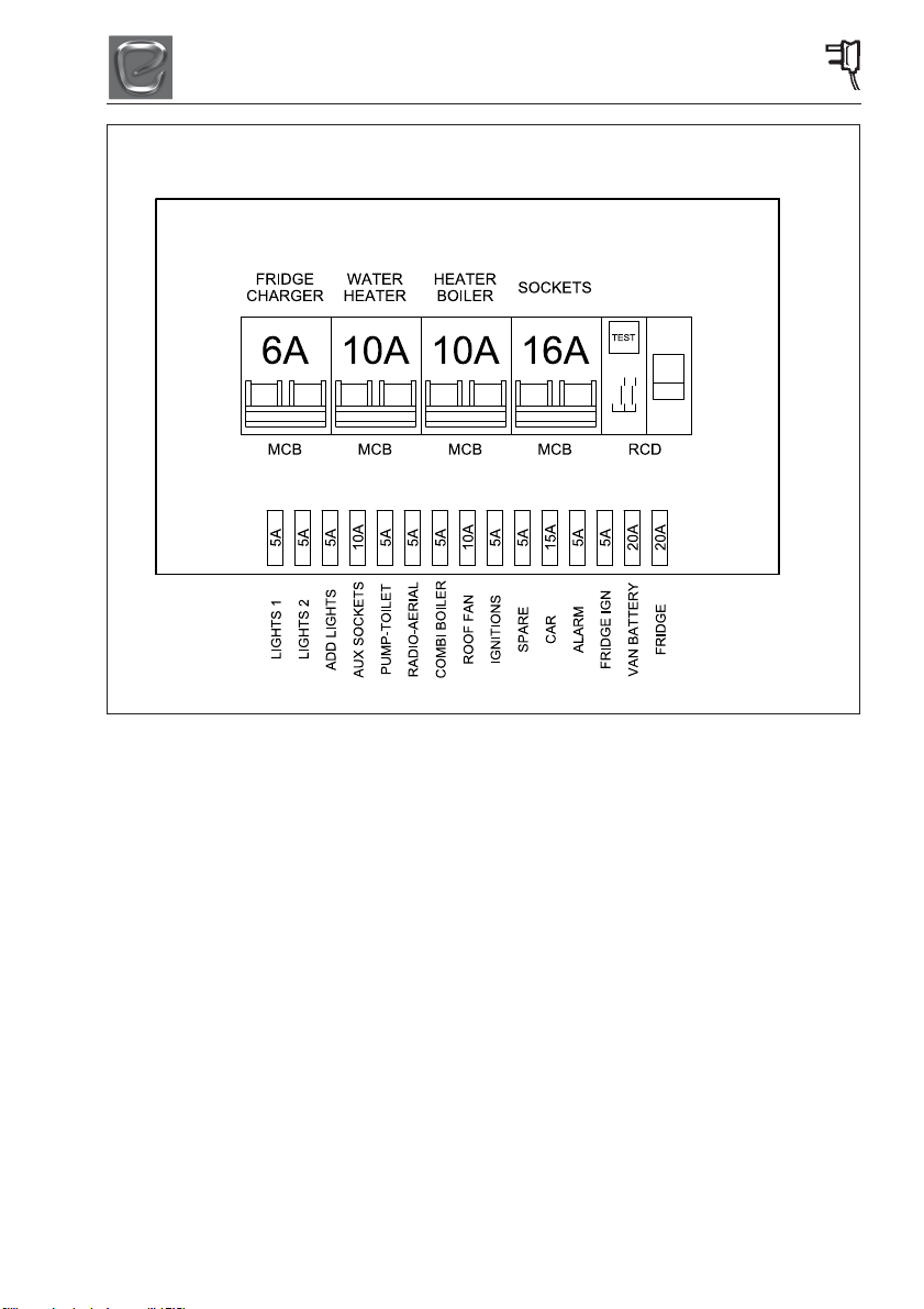
Mains Unit
The Mains Unit replaces the conventional
fuse box. Similar, but larger ones are often
fitted in new houses. The unit, normally
located on the front bed box, gives overloads
and earth leakage protection for the 230V
electrical supply in your campervan.
For normal operation all switches on the unit
need to be in the ON position. The switches
on the left of the unit are known as MCB’s
(miniature circuit breakers). These take the
place of the conventional fuse but are more
8-1

ELECTRICAL SYSTEM
convenient. In the event of a fault the MCB
‘trips’ i.e. automatically moves to the OFF
position. After elimination of the fault the
MCB can be re-set by switching to the ON
position (against the spring pressure in an
upwards direction). If an earth fault develops,
or a person was to touch a live piece of
equipment, the leakage of current to earth
should immediately operate the RCD
(residual current device) and ‘trip’ the main
switch, to the OFF position. This switch can
only be re-set after elimination of the fault.
Please note: In case of difficulty, consult an
approved electrical installation contractor
(who may be the local electricity board). It is
dangerous to attempt modifications and
additions yourself.
CAUTION: Lamp holder-plugs (bayonet- cap
adaptors) should not be used under any
circumstances.
Resetting the RCD
To re-set, operate the switch as for MCB’s.
Periodically, the RCD should be checked by
operating the test button marked ‘T’. The unit
should immediately switch to the OFF
position. If the unit does not switch off then a
qualified electrician should be consulted. If
the unit does switch off, the test is complete
and the switch can be re-set restoring the
supply back to normal.
Please note: Simultaneous operation of all
of the 230V mains electrical equipment may
not be possible. A typical UK site mains hookup point provides a maximum output of 16
amps and on some continental sites the
available output may be as low as 5 amps. If
your loading exceeds the site supply it may
trip the site circuit breaker. Please check the
available mains output with your site
operator. The following items need to be
added together if used simultaneously.
230V mains equipment typical consumption
figures:
• Refrigerator ............................... 0.50 amps
• Charger ..................................... 0.50 amps
• Water heater ............................... 3.9 amps
• Blown air heaters ........................ 8.5 amps
• Colour TV .................................. 3.33 amps
AUTOMATIC CHARGING SYSTEM
The battery charger will operate automatically
when the campervan is connected to the
mains outlet on a campervan site.
Note: The charging unit only charges the
leisure battery not the vehicle battery.
When the campervan engine is running the
12V system will not operate with the
exception of the 12V refrigerator.
Note: When the vehicle is in transit the
engines alternator will charge both the
vehicle and leisure batteries.
CHECK all campervan equipment is set-up to
accept the site supply before actually
switching on.
MAXIMUM BULB RATINGS FOR
INTERNAL LIGHTS
Type of Light Maximum Bulb Rating
Downlighters .................................. 1.2 watts
Reading lights ................................ 0.4 watts
Above locker strip light 500mm ...... 1.2 watts
Above locker strip light 800mm ...... 2.2 watts
Awning lights ..................................... 4 watts
Note: All LED lights can only be replaced
with a new complete unit and not a
replacement bulb.
CAUTION: It is recommended to set the
position of the reading light before switching
on. Do not look directly at LED lights.
8-2
ELECTRICAL SYSTEM
MAINS UNIT - CAMPERVAN
8-3

ELECTRICAL SYSTEM
8-4

HOW TO USE YOUR CAMPERVAN’S EQUIPMENT
HOW TO USE YOUR
CAMPERVAN’S EQUIPMENT
Within this section of your campervans
handbook we will give you brief details on
how to operate all of the campervans
equipment from the gas cooking equipment
to the window blinds. For further details on
the major equipment within your campervan
please read the individual appliance
instructions contained with your user
information pack.
Please note: Before attempting to use any
gas equipment please ensure that the LPG
tank contains gas and the valve is in the on
position. Also ensure the appliance isolation
valves are in the on position as shown in the
gas system section.
Please note: Before attempting to use any
electrical appliance please ensure that you
have connected the mains connection cable
to a mains hook up and that the mains
isolation switch is in the on position. Ensure
the 12V master switch is in the ON position.
This is found in the side of the unit next to the
entrance door.
9-1
HOW TO USE YOUR CAMPERVAN’S EQUIPMENT
W
CONTROL PANEL
Your new campervan is fitted with the control panel shown below.
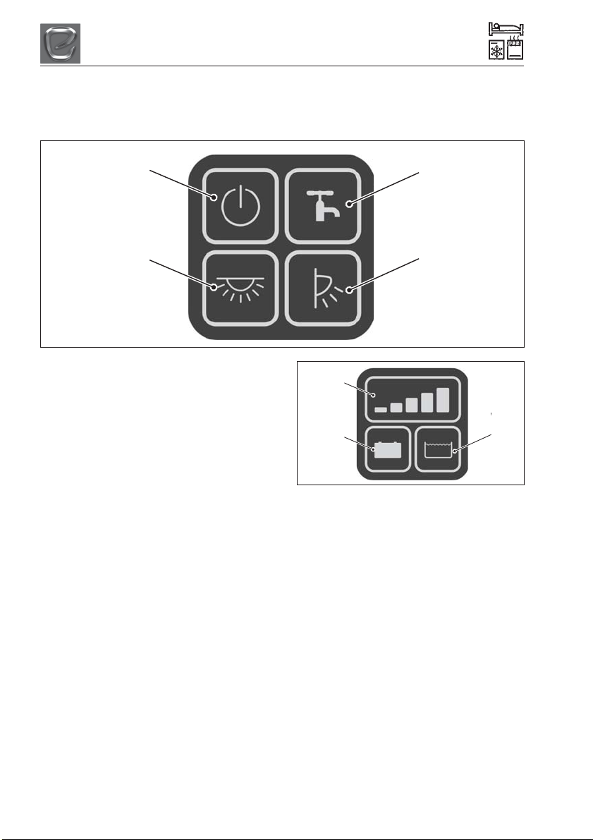
Vegas Button Control Panel
Master Button
Lights Button
Master Button
When the Master Button is pressed, the
control panel will switch power to all nonessential accessories.
• Some features, such as lights, will need
the Master Button to be switched on to
work.
Lights Button
When the Lights Button is pressed, the
control panel will switch power to all the
interior lights.
• If the Master Button is switched off then
this button will not function.
Pump Button
When the Pump Button is pressed, the
control panel will switch power to the water
pumps.
• Holding down the Pump Button forces the
internal pump to run regardless of tank
level. This is so that the user can purge
their water pipes.
Awning Button
When the Awning Button is pressed the
control panel will switch power to the exterior
awning light.
Pump Button
Awning Button
Display
Indicator
Leisure
Battery
Voltage
Button
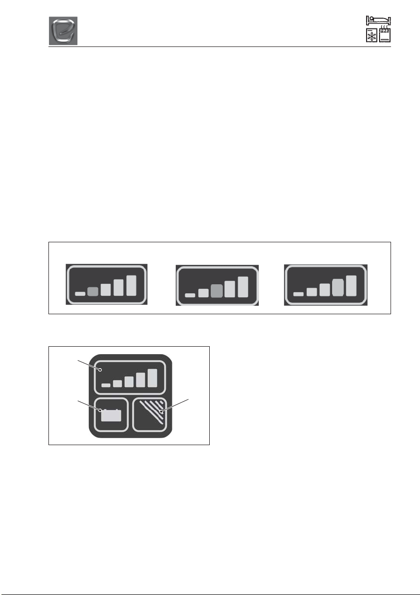
Display Indicator
The Display indicator on the Vegas Voltmeter
Panel is used to display the Leisure Battery
voltage and the Water level, depending on
which button is pressed.
• If a waste tank is fitted, the lowest
indicator will illuminate when the waste
tank is full.
• When the pump is running the 5th
indicator (Green) will illuminate to indicate
that the pump is currently running.
Leisure Battery Voltage Button
When the Leisure Battery Voltage Button is
pressed, the Display Indicator will light up and
display the voltage level of the Leisure
Battery.
Water Level Button
When the Water Level Button is pressed, the
Display Indicator will light up and display the
water level reading inside the water tank.
9-2
Water
Level
Button
HOW TO USE YOUR CAMPERVAN’S EQUIPMENT
Water Level Calibration
Before the Water Level Button is used for the
first time, you will need to calibrate the
Control Panel to your water tank.
• Make sure your water tank is at the
recommended maximum level before
starting the calibration process.
• You will need to re-calibrate the Control
Panel if you change water tank.
Use the following steps to calibrate your
Control Panel.
1. Hold down both the Voltage Button and
Water Level Button for 6 to 8 seconds to
get into calibration mode.
2. When you are in calibration mode, the
Display Indictor will light up depending on
which water probe you ha\ve installed.
Pressure Probe
5-Prong Probe
Vegas Voltmeter without Water or
Gas Level
Display
Indicator
Leisure
Battery
Voltage
Button
Button
not used
3. To cancel calibration mode, press and
hold Leisure Battery Voltage Button for
two seconds.
4. To start the calibration process, press
and hold the Water Level Button for two
seconds.
5. If the calibration process was successful,
the display will flash three times.
• If the calibration process is
successful, the Control Panel will
restart and be ready to use.
6. If the calibration process was
unsuccessful, the display will flash two
times.
• If the calibration process fails, go
back to step 2 to start the calibratio
process again.
Resistive Probe
Leisure Battery Voltage Button
When the Leisure Battery Voltage Button is
pressed, the Display Indicator will light up
and display the voltage level of the Leisure
Battery. The button on the right of the panel
is not used on this panel.
Display Indicator
The Display indicator on the Vegas Voltmeter
Panel is used to display the Leisure Battery
voltage.
ïIf a waste tank is fitted, the lowest indicator
will illuminate when the waste tank is full.
9-3
 Loading...