

elddis 2016 Buccaneer, CRUSADER Owner's Handbook Manual

Buccaneer
Touring Caravan
OWNERS
HANDBOOK
Issue 1

CONTENTS
WELCOME AND INTRODUCTION ........ 1-1
Model Year Designation .......................... 1-1
Buccaneer Technical Approvals .............. 1-1
GENERAL SAFETY ............................... 2-1
Ventilation ............................................... 2-2
High-Level Ventilation ............................. 2-2
Low-Level Ventilation .............................. 2-2
Ventilation in Separate Bedrooms........... 2-2
Gas Dispersal Holes ............................... 2-2
Petrol/Diesel Fumes ................................ 2-2
Fire Safety ............................................... 2-2
Fire Extinguishers ................................... 2-2
In Case Of Fire ........................................ 2-2
Fire Retardant Foams ............................. 2-2
Escape Paths .......................................... 2-2
Your Caravan Payload Explained ........... 2-3
PREPARING FOR THE ROAD............... 3-1
Caravan Towing Vehicle Weight Ratio .... 3-1
Loading ................................................... 3-1
Internal Loading & Checks ...................... 3-1
External Loading & Checks ..................... 3-2
Pre-Tow Checklist & Hitch-Up ................. 3-2
Winterhoff Stabiliser - Hitch Head
Operation ................................................ 3-2
Activating the Stabiliser ........................... 3-2
Checking the Stabiliser ........................... 3-2
Uncoupling .............................................. 3-3
Use of Your Caravans Breakaway Cable 3-4
Handbrake .............................................. 3-5
Cables ..................................................... 3-5
TOWING AND DRIVING ......................... 4-1
Reversing ................................................ 4-1
Speed Limits ........................................... 4-1
Setting Off ............................................... 4-1
Caravan Handling ................................... 4-1
Motorway Driving .................................... 4-2
Towing Covers ........................................ 4-2
Tyre and Wheel Checks .......................... 4-2
ARRIVING ON SITE ............................... 5-1
Check Site Regulations ........................... 5-1
Selecting a Pitch ..................................... 5-1
The E&P Hydraulics Levelsystem ........... 5-1
GETTING STARTED .............................. 6-1
Electricity ................................................. 6-1
Power Supply Charger ............................ 6-1
12v Systems: .......................................... 6-1
Generator/Charger .................................. 6-1
Electricity Mains Supply .......................... 6-1
Connecting To Mains Supply On
Arrival at Site ........................................... 6-1
Disconnecting Mains Supply When
Leaving Site ............................................ 6-2
Overseas Electrical Connection .............. 6-2
Gas Safety Advice................................... 6-3
Facts about LPG ..................................... 6-3
Awning Spaces, LPG and Appliance
Exhaust ................................................... 6-3
LPG Gas System .................................... 6-3
Gas Supply ............................................. 6-4
Connection .............................................. 6-4
Changing a Gas Cylinder ........................ 6-4
Auto Changeover Gas Regulator ............ 6-4
High Pressure Gas Hoses ...................... 6-6
Water System.......................................... 6-7
High Flow Watermaster Pump with
Intelligent Control (IC) ............................. 6-7
Maintenance ........................................... 6-9
Helpful Hints ............................................ 6-9
Troubleshooting .................................... 6-10
Diagnostic Codes .................................. 6-10
Winterising ............................................ 6-10
ELECTRICAL SYSTEM .......................... 7-1
12v Power Supply ................................... 7-1
Battery Installation .................................. 7-1
Battery Maintenance ............................... 7-1
Generators / Charger .............................. 7-1
230v Power Supply ................................. 7-1
Mains Unit ............................................... 7-1
Resetting the RCD .................................. 7-2
Automatic Charging System ................... 7-2
Maximum Bulb Ratings for Internal Lights7-2
HOW TO USE YOUR CARAVAN’S
EQUIPMENT ........................................... 8-1
Control panel ........................................... 8-2
Combined Cooker, Hob, Oven and Grill.. 8-3
Using the Hotplate Gas Burners ............. 8-3
Using the Electric Hotplate ...................... 8-4
Using the Grill ......................................... 8-4
Using the Oven ....................................... 8-5
Oven Temperature Control ...................... 8-5
Refrigerator ............................................. 8-7
Operation ................................................ 8-7
Defrosting ............................................... 8-11
Switching off Refrigerator ....................... 8-11
Winter Operation ................................... 8-12
Alde Heating ......................................... 8-13
Alde 3020 Control Panel ....................... 8-13
Whale Watermaster® Exterior Water
Pump with Intelligent Control® .............. 8-16
CONTENTS-1
MY2016/Buccaneer

CONTENTS
Battery Charger ..................................... 8-24
Smoke Alarm ......................................... 8-24
Nuisance Alarms ................................... 8-25
Battery Replacement ............................ 8-25
Cleaning your alarm .............................. 8-25
Carbon Monoxide Alarm ....................... 8-26
Recognising Alarm Signals and
Warnings ............................................... 8-26
Using your Alarm................................... 8-26
Switching on your CO Alarm ................. 8-26
Re-setting the Alarm ............................. 8-26
Replacement of Batteries ...................... 8-26
Carbon Monoxide Alarm Procedure ...... 8-27
Maintenance of your Alarm ................... 8-27
Thetford Cassette C260S Toilet ............ 8-28
Parts ...................................................... 8-28
Optional Features ................................. 8-28
Preparing for Use (Standard) ................ 8-28
Preparing for Use with Optional
Features ................................................ 8-30
Using the Toilet (Standard).................... 8-30
Using the Toilet with Optional Features. 8-30
Emptying ............................................... 8-30
Emptying with Optional Features .......... 8-31
Cleaning and Maintenance ................... 8-31
Toilet Bowl ............................................. 8-31
Waste Holding Tank .............................. 8-32
Winter Operation ................................... 8-32
Storage ................................................. 8-32
Toilet Unit Malfunctions ......................... 8-33
Rooflights .............................................. 8-34
The Omivent (12v) Rooflight ................. 8-34
Midi Heki Rooflight ................................ 8-34
MPK Rooflight ....................................... 8-35
Windows ............................................... 8-36
Polyplastic Window Opening ................ 8-36
Blinds & Flyscreens .............................. 8-36
Flyscreens ............................................. 8-36
Shower .................................................. 8-36
Taps ...................................................... 8-37
Gas Locker Door ................................... 8-37
Internal Doors ....................................... 8-38
Magnetic Catches ................................. 8-38
Sprung Hinges ...................................... 8-38
High Level Locker ................................. 8-39
Sliding Doors ......................................... 8-39
Bed Make-up ......................................... 8-40
Front Wrap Round Seating (Option) ..... 8-40
Removable Drawer Locker ................... 8-41
Satellite Dish (Optional) ........................ 8-41
Radio/CD with MP3 Connectivity .......... 8-41
Teleco TV Aerial .................................... 8-41
CONTENTS-2
How to use your TV Aerial..................... 8-43
Digital TV set-up Guide ......................... 8-43
Troubleshooting Guide .......................... 8-43
Protect - Autowatch Alarm System ........ 8-45
BPW Intelligent Drive Control (iDc)
System .................................................. 8-46
SECURITY .............................................. 9-1
Caravan Theft ......................................... 9-1
Diamond Standard Wheel Lock .............. 9-2
How to fit your Diamond Standard
Wheel Lock ............................................. 9-2
Hints for using the Diamond Standard
Wheel Lock ............................................. 9-2
Key Card ................................................. 9-2
CRIS - The Caravan Registration and
Identification Scheme .............................. 9-3
Window Etching & Chassis Marking ....... 9-3
Electronic Tagging ................................... 9-3
CARE OF YOUR CARAVAN ................ 10-1
Exterior Cleaning .................................. 10-1
Acrylic Windows .................................... 10-1
Care Instructions for Seitz Windows ..... 10-1
Care Instructions for Seitz Rooflights .... 10-1
Window Blinds & Flyscreens ................. 10-1
Winterisation/Storage ............................ 10-1
Interior Walls ......................................... 10-1
Furniture ................................................ 10-1
Cooking Equipment ............................... 10-2
Soft Furnishings .................................... 10-2
Carpets ................................................. 10-2
Winterisation and Storage ..................... 10-3
Shower Trays, Shower Room and
Wash Basin Fittings .............................. 10-3
Cleaning of all Taps ............................... 10-3
Water Containers .................................. 10-4
Water Systems - Sterilisation ................ 10-4
Thetford Toilet ....................................... 10-5
Chassis Mounted Spare Wheel Carrier 10-6
Tyres ..................................................... 10-6
Pressures .............................................. 10-6
Tyre Wear and Damage ........................ 10-6
Changing a Wheel ................................ 10-6
Jacking up your Buccaneer Caravan .... 10-7
Lubrication ............................................ 10-7
Maintenance of your BPW Chassis ...... 10-8
Procurement of Spare Parts ................. 10-8
Caravan Motor Movers ......................... 10-8
STORAGE ............................................ 11-1
Long Term & Winter Storage .................. 11-1
Caravan Covers ..................................... 11-1
Power Drain ........................................... 11-1

CONTENTS
CARAVAN WARRANTY COVER ......... 12-1
Non Warranty Repairs........................... 12-3
Remedial Work...................................... 12-3
CARAVAN CONSTRUCTION -
MAIN COMPONENTS .......................... 13-1
BPW Chassis ........................................ 13-1
Braking System ..................................... 13-1
Solid Construction Body Shell ............... 13-1
Windows ............................................... 13-1
Insulation ............................................... 13-1
Front Panel and Gas Bottle
Locker Door .......................................... 13-1
Awning Channel .................................... 13-1
EQUIPMENT LIST ................................ 14-1
Buccaneer ............................................. 14-1
WIRING DIAGRAM - BUCCANEER .... 15-1
Road Lights - Buccaneer ...................... 15-2
GENERAL QUESTIONS ...................... 16-1
GLOSSARY .......................................... 17-1
SERVICE DOCUMENTS ...................... 18-1
NOTIFICATION OF CHANGE OF
OWNERSHIP ........................................ 19-1
NOTIFICATION OF CHANGE TO
NAME AND ADDRESS ........................ 20-1
USEFUL ADDRESSES ........................ 21-1
INDEX ................................................... 22-1
CONTENTS-3

CONTENTS
CONTENTS-4

INTRODUCTION
WELCOME AND
INTRODUCTION
Congratulations on choosing a Buccaneer
Touring Caravan.
This Owner’s Handbook has been prepared
for your guidance to help you derive the
greatest amount of pleasure from the use of
your caravan and your leisure time. We
strongly recommend that you read this guide
thoroughly so that you are fully aware of all
the caravan’s features, equipment and
systems.
Additional information and detailed appliance
instruction manuals are also contained in
your Owner’s Information Pack which can be
found within the kit box supplied with your
caravan.
Your new Buccaneer caravan has been
designed as a recreational vehicle and is
intended for recreational use only. It is not
intended for business, hire use or for
permanent habitation. Buccaneer accepts
no liability if the caravan is used for any
purpose other than recreational/holiday
use. Any use other than recreational/
holiday use will invalidate your warranty.
Your caravan has been designed for towing
behind a normal motor car. Additional care
should be exercised when towing with a 4x4
because of the ‘off-road’ nature of the
suspension. Owners should not tow their
touring caravans with commercial vehicles.
When selecting a towing vehicle it is
recommended that you consult the Caravan
Towing Code, which is available from the
NCC.
By following the instructions provided in this
handbook and maintaining your caravan in a
first class roadworthy condition, you are sure
to have many years of carefree use.
To ensure the very best quality and reliability
all touring caravan designs and new
developments are rigorously tested.
Therefore Buccaneer will accept no liability or
uphold the warranty if the caravan is altered
or modified in such a way that would
adversely affect the reliability.
Please note: It is a condition of your
warranty that the caravan must have an
“annual service” carried out by a Buccaneer
approved Retailer / Service Centre or NCC
Approved Workshop or NCC equivalent
standard as set out in this handbook and a
record is kept. Pages are provided in the
back of this guide, for your assistance.
A Buccaneer Approved Retailer / Service
Centre will be able to supply any replacement
parts for your caravan, should the need arise,
and in most cases any accessories you may
require.
Please note: It is not possible to purchase
replacement parts direct from Buccaneer.
Changing market and supply situations may
prevent us from maintaining the exact
specification details in this guide and we
therefore reserve the right to alter
specifications as materials and conditions
demand.
Enjoy your new caravan
Model Year Designation
All Touring caravans manufactured by
Buccaneer are designated by their model
year. The 2016 model year runs from 1st
September 2015 to 31st August 2016.
Buccaneer Technical Approvals
All Buccaneer Caravans have been
European Commission Whole Vehicle Type
Approved via the Vehicle Certification Agency
(VCA).
In order to ensure your new caravan is safe
to use, Buccaneer are members of and have
been inspected by the following bodies.
NCC who operated a certification scheme to
ensure compliance with the European safety
standards for caravans.
National Inspection Council for Electrical
Installation and Contracting (NICEIC) who
carry out an annual inspection of Buccaneer
electrical installations within caravans.
Gas Safe Register™ approved installers
carry out an annual inspection to ensure that
the gas installations carried out by Buccaneer
fully comply with all relevant regulations and
standards.
Buccaneer has also obtained ISO9001:2015
accreditation and this is audited by SGS UK
Limited
1-1

INTRODUCTION
1-2

GENERAL SAFETY
GENERAL SAFETY
Please read before using your new
caravan.
In order for you to get the most out of your
new Buccaneer caravan it is necessary for
you to be aware of the following:
(i) Do not obstruct ventilators and clean
them regularly, it is advisable to clean
and check all the ventilators annually
for blockages and where necessary
rectify any blockages found.
(ii) Inspect the high pressure flexible gas
hose (available from your retailer)
regularly for deterioration and renew
as necessary, with an approved type,
in any case no later than the expiry
date stated on the hose.
(iii) Ensure the gas supply and all
appliances are turned off before towing
your caravan.
(iv) If your caravan has been fitted with a
gas BBQ point it must be only used for
its intended purpose. Do not use a
gas barbeque within an awning.
(v) Never use portable cooking or heating
equipment inside your caravan. Do not
use your fitted cooking equipment as
heating at any time.
(vi) Never allow modification to your gas or
electrical system unless qualified
persons carry them out. All
modification to the gas system must be
carried out by a Gas Safe Register™
approved gas fitter. Any modifications
carried out on the electrical system
must be carried out by an electrician
on the roll of the NICEIC or be a
member of the ECA.
(vii) If you suspect there is a gas leak
please open all the windows then
vacate the caravan. Turn off the gas
container if safe to do so, then contact
your nearest Buccaneer Retailer to
arrange for them to check the gas
system.
(viii) In the interest of safety, replacement
parts for an appliance should conform
to the appliance manufacturer’s
specifications and should be fitted by
them or an authorised agent.
(ix) It is recommended that you provide a
dry powder fire extinguisher complying
with ISO 7165 of at least 1KG capacity
by the exit door and a fire blanket next
to the cooker. Ensure you read the
‘advice to occupier label’ fitted to your
caravan usually found on the inside of
the wardrobe door.
(x) Never exceed your caravans Maximum
Technical Permissible Laden Mass.
(see Caravan Towing Vehicle Weight
Ratio).
(xi) The laden nose weight for your
caravan should not exceed the lower
of the following:
• Towing vehicles maximum nose
weight.
• Tow bar maximum nose weight.
• The caravan’s maximum nose weight
(xii) Ensure heavy and large items are
secured before towing your new
caravan to reduce the risk of damage
being caused while the caravan is in
motion.
(xiii) Pull out worktop extensions, where
fitted, are only designed to take a
maximum weight of 6kgs.
(xiv) Where high level bunks are fitted, care
should be taken when used by
children. The protection against falling
out must be in place when the bunk is
used.
(xv) When your caravan is connected to
your towing vehicle it should be level
or slightly nose down.
(xvi) When your caravan is loaded to its
MTPLM and the weight distributed in
accordance with the handbook, your
caravan is designed to be towed at a
maximum speed of 100kmh/60mph.
(xvii) It is illegal to tow your caravan
whilst it is occupied.
(xviii) Do not leave children under 14 years
of age unattended in your caravan.
(xix) Your vehicles MIRO is calculated with
no water on board. To travel with water
you must take account of the water in
your vehicle payload. 1 litre of water =
1Kg.
2-1

GENERAL SAFETY
VENTILATION
All caravans manufactured by Buccaneer are
ventilated at both high and low level in
accordance with BSEN 721 Safety
Ventilation.
High-Level Ventilation
This is always provided by fixed ventilation
within the fitted roof skylight. These roof
skylights should be cleaned annually by use
of a small brush to remove any dust that may
have accumulated around the mesh fitted.
On some roof skylights the mesh can be
easily removed to aid cleaning. On fanassisted roof skylights it is essential that the
fan is switched off prior to cleaning
Low-Level Ventilation
Low level ventilation is provided within the
living area of your new caravan and these
can be identified by the fitting of a black
cover to prevent them from being obstructed.
This cover must not be removed. In order to
clean the ventilator, remove the cover by
undoing the two screws and clean using a
small brush. It is essential that the cover is
replaced once cleaning is complete.
Ventilation in Separate Bedrooms
In caravans with separated sleeping areas,
separate ventilation is required and is
provided via a roof skylight at high level and
a ventilator at low level within a bed box or
under the fixed bed.
Gas Dispersal Holes
All appliances and gas taps have a gas
dispersal hole nearby. It is essential that
these are not blocked or made ineffective.
Petrol/Diesel Fumes
The fitting of a tail pipe to your exhaust will
reduce the possibility of fumes entering your
caravan through the front fixed ventilation
points.
FIRE SAFETY
Fire Extinguishers
It is recommended that a 1 kg (2lb) minimum
capacity dry powder fire extinguisher be
carried inside your caravan at all times. A
pan fire must not have an extinguisher aimed
at it, but must be smothered with a fire
blanket.
In Case Of Fire
(i) Get everyone out of the caravan as
quickly as possible using whichever exit
is quickest including windows. Do not
stop to collect any personal items.
(ii) Raise the alarm. Call the fire brigade.
(iii) Turn off the gas container valve if safe to
do so.
Fire Retardant Foams
All caravans are equipped with either
Combustion Modified High Resilient
(C.M.H.R.) foam cushions or sprung
mattresses and fire retardent fabric. All
furnishings and fabrics used by Buccaneer
comply with the Furniture and Furnishings
(Fire Safety) Regulations. In addition all
upholstery is made of fire retardant fabric.
Escape Paths
Your new touring caravan has been provided
with escape paths to be used in the event of
an emergency. One of which is always the
main habitation door and others are the large
windows to be used where necessary. Care
must be taken when exiting via a window due
to the potential drop to ground level.
IMPORTANT: Your attention is drawn to
the notice affixed in the caravan’s
wardrobe advising on fire prevention,
ventilation and what to do in case of fire.
2-2

GENERAL SAFETY
YOUR CARAVAN PAYLOAD
EXPLAINED
Definitions
Plated maximum technical
permissible laden mass (PMTPLM)
As specified by Buccaneer and in compliance
with the European Directive on Masses and
dimensions of vehicles.
Actual MTPLM
Maximum mass of the vehicle, which takes
into account operating conditions including,
factors such as the strength of materials,
loading capacity of the tyres etc.
Mass of the caravan in running
order (MIRO)
This is the weight of your caravan as it
leaves our factory plus the following:
A mass of 10kgs per gas cylinder, the
cylinder number is equal to the number
of connections provided at the regulator.
Personal effects payload (PEP)
This is calculated by the following formula:
10L + 10N + 50
L is the body length of the caravan in
meters.
N is the number of berths.
50 is for normal equipment carried in the
caravan, a sample list is given below.
Kettle ................................... 0.5kgs
Bed linen ................................. 6kgs
Crockery ................................. 5kgs
Saucepans .............................. 3kgs
Wastemaster ........................... 6kgs
Aquaroll (empty) ..................... 5kgs
Waste bin ................................. 1kg
Cutlery .................................... 2kgs
To ilet fluid etc ....................... 2.5kgs
Battery .................................. 25kgs
Optional equipment payload (OEP)
This is an amount of weight provided by us
for factory fitted options.
Please note: Any options fitted by the
retailer will reduce the overall payload
available to the customer.
User Payload is the sum of the PEP and
OEP.
Note: It may be possible to upgrade your
Plated MTPLM to the Actual MTPLM up to
the caravan being 3 years old, there is an
administration fee for this service.
Note: Please ensure you never load your
caravan above the plated MTPLM.
Note: Please take care to ensure you have
allowed for the mass of all the items you
intend to take in your caravan.
2-3

GENERAL SAFETY
2-4

PREPARING FOR THE ROAD
PREPARING FOR THE ROAD
CARAVAN TOWING VEHICLE
WEIGHT RATIO
This ratio has a major influence on stability. It
is recommended that:
(i) The laden nose weight for your caravan
should not exceed the lower of the
following:
* Towing vehicles maximum nose
weight,
* Tow bar maximum nose weight
* The caravan’s maximum nose weight.
(ii) The actual laden weight of the caravan
should always be kept as light as
possible. The lighter it is whilst being
towed on a road, the safer the outfit
combination will be.
(iii) What you are able to tow is dependent
on your driving licence.
(iv) If you are a B licence holder you can
only tow a car/caravan combination of
total weight not exceeding 3500kgs and
the cars kerb weight must be greater
than the caravans plated MTPLM.
Note: It is strongly recommended that
the caravan plated MTPLM should not
exceed the cars kerb weight.
(v) If you hold a B + E licence you can tow
up to a combination weight of 7000kgs.
(vi) The greater the actual laden weight of
the caravan in relation to the kerb weight
of the towing vehicle the more careful
and experienced the driver needs to be
and the lower the speed at which
instability could occur.
WARNING: It is strongly recommended
the loaded weight of the caravan does not
exceed the kerb weight of the towing
vehicle.
LOADING
Always lower and secure the jockey wheel
and the four corner steadies (with the brace
provided) before entering the caravan. This
will ensure that the caravan does not tip up
when you are inside.
Please note: Corner steadies should not be
used as a jacking or levelling device.
Internal Loading & Checks
When loading your caravan it is advisable to:
(i) Distribute items evenly over the axle and
as low as possible to optimise road
holding and achieve the best possible
braking effect.
(ii) Do not overload on one side as this will
cause the caravan to lean and affect the
road holding and stability.
(iii) Do not stow tins, bottles or heavy items
in overhead lockers when towing.
(iv) Loose articles should be stowed
securely to avoid movement and
possible damage.
(v) Ensure that all lockers, cupboard doors
and showers doors are closed and room
partitions are secured.
(vi) Secure all bunks (if appropriate).
(vii) Store the main dining table in its transit
position.
(viii) Set the refrigerator for 12V operation if
any fresh food is stored in it and ensure
the door is locked.
(ix) Fully close and lock all windows and
rooflights. Never tow with windows on
night setting.
(x) Leave all curtains and blinds open to
prevent damage in transit. If your
caravan has a rear window this may aid
visibility.
(xi) Ensure you remove all items from the
microwave and cocktail cabinet before
towing.
3-1
PREPARING FOR THE ROAD
External Loading & Checks
(i) Gas cylinders should only be stored,
correctly positioned, and secured in the
gas bottle locker. The gas should be
turned off.
(ii) The leisure battery is stored and
secured in the battery locker box, set
into the tray provided and secured.
(iii) Any external connections (battery
chargers, connecting cables etc), should
be disconnected and stowed.
(iv) Check that all exterior locker doors are
secure and locked.
(v) Secure and lock the main caravan
entrance door.
PRE-TOW CHECKLIST & HITCH-UP
Having loaded the touring caravan and
secured the lockers and main entrance door:
(i) Check touring caravan wheel bolts are
torque tightened to the required level
(See Index - Changing a Wheel).
(ii) Check tyre pressures (Refer to the
Technical Data Sheet) and tyre condition
for roadworthiness.
(iii) Ensure the jockey wheel is down, in
good contact with the ground, clamp
tightly secured, and the caravan
handbrake is fully on.
(iv) Wind up the corner steadies.
(v) Reverse the car close up to the
caravan’s hitch. It is advisable to seek
assistance to guide you so that the car
tow ball aligns with the caravan’s hitch.
(Use of the caravan handbrake is
advised. Extreme caution should be
taken if manoeuvring the caravan down
hill or on wet, slippery surfaces).
(vi) Make sure the jockey wheel height is
sufficient for the hitch head to clear the
towing vehicles tow ball.
(v) Manoeuvre the hitch head over the tow
ball and lower the jockey wheel using
the winding handle, until the hitch head
opening sits comfortably over the tow
bar ball.
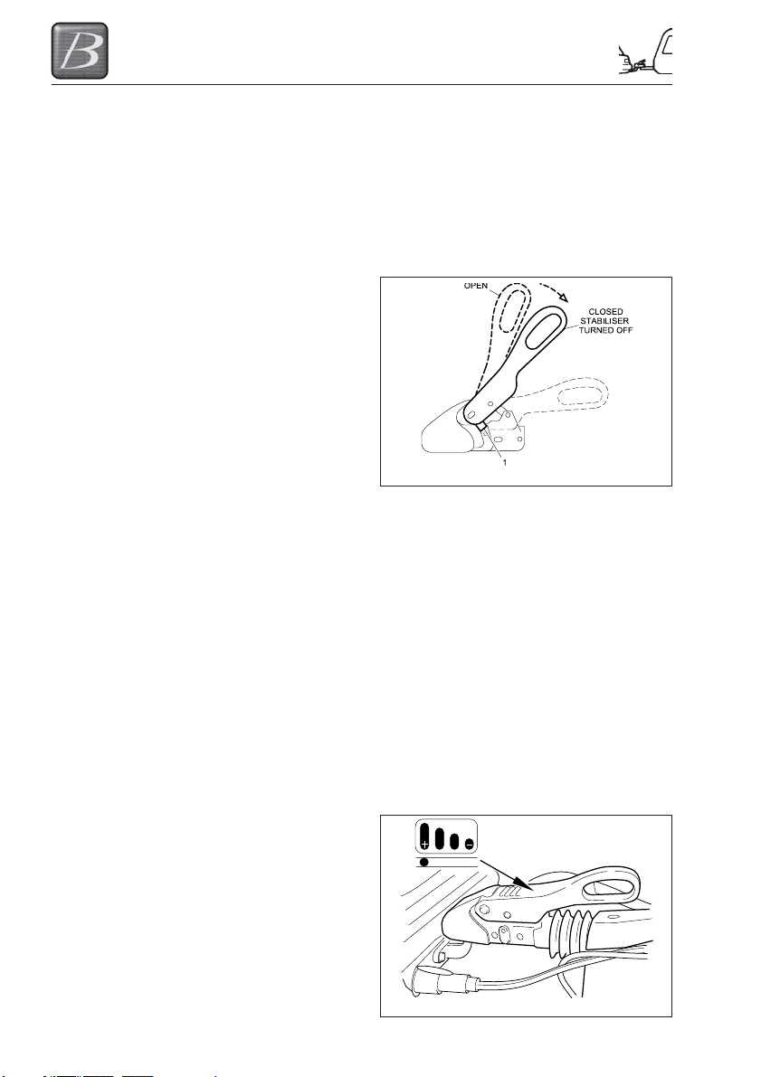
WINTERHOFF STABILISER - HITCH
HEAD OPERATION
Coupling
The opened ball coupling is placed over the
tow ball of the towing vehicle. As the coupling
load is applied to the tow ball the coupling will
automatically close, this is indicated when the
security lugs become parallel on the side of
the housing. (Fig 3.1)
Fig 3-1
Activating the stabiliser
The operating handle will not operate until the
automatic closing function has been engaged.
The handle can now be fully pushed down.
The hitch will remain coupled with the
stabiliser deactivated to facilitate easier
manoeuvring.
Checking the stabiliser
With the caravan coupled to your towing
vehicle and the stabiliser activated, the
condition of the friction linings can be
checked. The wear indicator (as shown in Fig
3.2) is within the top of the operating handle.
The bar graph is marked with (+) and (-)
symbols with (+) indicating good condition of
the pads and (-) indicating that the pads
should be checked.
3-2
Fig 3-2

PREPARING FOR THE ROAD
Disengaging the stabiliser
Lift up the operating handle with care to
release the sprung loaded stabiliser function.
Fig 3-3
Uncoupling
Before uncoupling disconnect the electrical
connections and breakaway cable. Also
check that it is safe to uncouple your caravan
taking into account any gradients. With the
stabiliser function disengaged,
simultaneously pull back and lift the operating
handle, this swings the securing lugs out of
the locked position allowing the operating
handle to be lifted into the fully open position.
Before operating the jockey wheel, which will
lift the caravan free of the tow ball, check that
both caravan and towing vehicle handbrakes
are applied!
If the caravan is not to be used for any
lengthy period of time we recommend the ball
coupling is kept in the closed position. This
can be done easily by pressing the safety ball
into the ball space and slowly closing the
operating lever.
3-3
PREPARING FOR THE ROAD
USE OF YOUR CARAVANS
BREAKAWAY CABLE
The law requires that any trailer with a
MTPLM (GVW) exceeding 750 kg must have
a braking system and it must work. If such a
trailer becomes detached from the tow vehicle
then these brakes must be applied
automatically by way of the breakaway cable.
This breakaway cable is an important part of
the management of the braking system and
when the trailer is built the braking system is
part of the certification process for the safe
use of the trailer - so any replacement parts
must be equivalent to the original parts fitted.
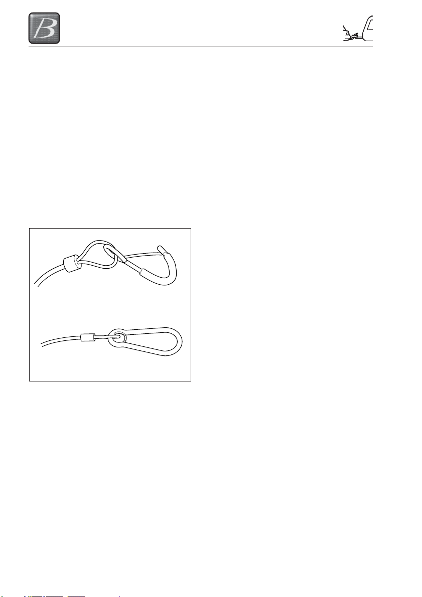
There are two types of breakaway cable in
use in the UK. One uses a spring clip (one of
the Al-Ko versions, the other uses a Karabiner
Spring type clip
Karabiner type clip
clip (available from Al-Ko and BPW).
Looking at the two clips it is easy to see that
there is a difference.
The spring clip type is designed to be hooked
back over the breakaway cable when it is
fitted to the tow vehicle and must always be
used this way.
The Karabiner type is designed to be secured
onto a mounting point on the two vehicle, it
does not need to pass back over the cable to
secure it in place (but can if necessary).
So how should the breakaway cable be
secured to the tow vehicle? In the absence of
specific advice from the manufacturer/supplier
follow these simple guidelines:
Fixed tow ball systems
The cable with spring clip should be passed
behind the towbar assembly (where cable
length is sufficient) and then clipped back on
itself. The cable should be in as straight a
path as possible to ensure correct operation.
Where there is insufficient cable length then
the cable should pass around the base of the
tow ball and then be clipped back on itself.
Detachable tow bar systems
Vehicles with a detachable tow bar system
may have a securing point provided on the
tow bar assembly. This securing point should
be part of the towbar assembly fitted to the
tow vehicle but this securing point may not be
large enough to allow the spring clip type
fastener to pass completely through, do not
be tempted to clip onto the securing point
directly. Where this is the case, or where
there is no hooking point provided, then the
cable should pass around the tow ball
assembly and then clipped back on itself.
Where the towbar provides a securing point
and a Karabiner type fastening is provided,
then this can be secured to the securing
point. Make sure that it is completely closed
to ensure that it operates correctly.
Be careful to check that the cable does not
sag so much that it could drag on the ground
- if it does it may become damaged or catch
on debris on the road surface. Also ensure
that the cable is long enough to allow for any
sharp turns, otherwise the cable may
inadvertently apply the trailer brakes and this
could cause damage to the brake
components.
Remember to check the breakaway cable for
any signs of damage. The cable is designed
to apply the trailer brakes and then snap
once the brakes are applied so any damage
may result in premature failure and the
brakes not being properly applied.
And ... remember ... Many inadvertent
detachments occur at low speed - normally
as a result of the hitch head not being
engaged properly onto the tow ball assembly.
A low speed detachment may not result in the
breakaway cable operating properly - so
ALWAYS check that the head is fully secure
before setting off.
3-4
PREPARING FOR THE ROAD
BEFORE SETTING OFF
(i) Connect the 13 pin plug on the caravan
A-frame to the towing vehicle.
(ii) Check that all tail-lights, brake lights,
road lights and indicators work correctly.
(iii) Ensure that the correct vehicle license /
registration plate is attached to the rear
of the touring caravan.
(iv) Using the jockey wheel lift the tow ball
slightly to check hitch is locked onto the
ball
(v) Wind up the jockey wheel until the wheel
supports locate into the cut out sections
at the base of the winding section.
(vi) Raise and secure the jockey wheel
using the clamp. The jockey wheel
should be parallel to the direction of
travel at all times.
(vii) Check condition of and secure the
breakaway cable to the tow vehicle.
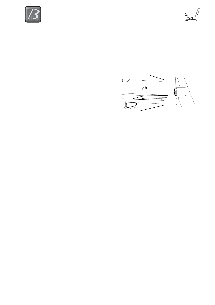
HANDBRAKE
Your caravan is fitted with BPW running gear
and handbrake. It is essential that prior to
towing you ensure that your handbrake is in
the fully off position. This can be confirmed
by ensuring that the handbrake arm is resting
on the blue stop fitted to the side of the A
frame as shown in Fig 3-4 below.
Fig 3-4
CABLES
For peace of mind, you may wish to check
the ability of the cables to be able to cope
with towing the vehicle at extreme angles
before setting off. To do so position the
vehicle at alternate extreme angles and
check that the cables do not pull too tight, are
liable to stretch or become unplugged. No
cables should be allowed to touch the ground
as they will wear and become damaged and
ineffective.
Please Note: If having followed this advice,
you feel you cannot achieve a satisfactory
cable arrangement, consult your caravan or
tow bar supplier or service agent.
3-5

PREPARING FOR THE ROAD
3-6
TOWING AND DRIVING
TOWING AND DRIVING
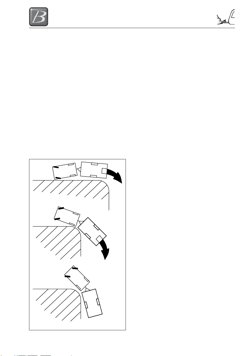
REVERSING
It is advisable to have a second person
assisting when reversing the caravan.
Start practising by choosing a left-hand bend
for ease. Reverse slowly; turning the wheel,
initially the opposite way to the direction you
want the caravan to go.
Now the front of the caravan is nudged out
and is moving the rear in the intended
direction. Take care not to hit the caravan
with the car!
Midways through the manoeuvre, when the
caravan is correctly angled, reduce speed to
a crawl and gradually apply opposite lock.
Make the car follow the caravan round then
finally straighten up.
Please note: Proficiency at reversing can
only be achieved with practice.
SPEED LIMITS
• Always adhere to the speed limits in
force.
• When national speed limits apply, when
towing on a single carriageway, the
speed limit is reduced to 50mph. Dual
carriageway and motorways, the speed
limit is reduced to 60mph.
SETTING OFF
(i) Pull away smoothly in the towing
vehicle. Allow more engine speed to
produce the power to move the
additional weight of the caravan.
(ii) Avoid wear and tear on the clutch and
transmission by taking extra care not to
‘ride’ the clutch.
(iii) Change gears smoothly. Try not to jerk
the clutch.
CARAVAN HANDLING
(i) Allow for the caravan being wider than
the car. Ensure you have a clear view
to the rear. This may require the fitting
of extended mirrors for towing your
caravan.
(ii) Give yourself more room when
cornering to ensure your caravan
wheels do not strike the kerb.
(iii) When passing other vehicles, allow
more than the normal clearance for
driving solo.
(iv) Allow longer to obtain a fast enough
speed to pass other vehicles.
(v) Allow for the vehicle being twice its
normal length. Do not suddenly swing
out.
(vi) Carry out all manoeuvres as smoothly
as possible.
(vii) Use the wing mirror to check the
caravan has clearly passed other road
users when overtaking and changing
lanes.
(viii) Adverse weather conditions may affect
the steering and braking characteristics
of your caravan.
Fig 4-1
4-1

TOWING AND DRIVING
MOTORWAY DRIVING
Important Points:
1. Caravans may not be towed in the
outside lane of a three or four lane
motorway.
2. Reduce speed:
a) In high or cross winds
b) Downhill
c) In poor visibility
3. High sided vehicles cause air buffeting,
so extra care must be taken when
passing or being passed. As much space
as possible should be given to avoid the
drag created by the high sided vehicle.
4. When going uphill, change gear in good
time. If your car is running short of power
or is behind a slower vehicle, keep well
into the nearside and out of the way of
other vehicles. Remember that some hills
can be ascended with relative ease often
pose an unexpected challenge if you
come to a standstill in traffic and then
have to re-start from scratch.
5. When going downhill, take extra care to
ensure you do not gain speed. This can
be avoided by changing down a gear and
reducing speed as you approach the
slope. Don’t leave this gear change too
late. Using low gears throughout the
descent will reduce the strain on the car’s
brakes. For automatics, you may need to
manually change to a lower gear in
anticipation of the effect caused by the
gradient change.
TOWING COVERS
We do not recommend that you tow with
covers on as it can obscure the road lights
fitted.
Tyre and wheel checks
Tyres are an essential part of the safe use of
your caravan and it is important that they are
properly maintained to make sure that they
do what they are intended to do - carry the
load and grip the road as well as bringing you
and your caravan to a safe stop.
So how do we know we have the correct
tyres for our caravan and how do we know
that they are still safe to use?
When your caravan was first manufactured
the tyres fitted were chosen because they
would carry the load that the caravan was
designed to carry.
Note that it may be possible to increase the
maximum technically permissible laden mass
(MTPLM) of the caravan depending on the
capacity of the chassis but it is essential that
the tyres are checked to verify that they are
suitable for the extra loading if this option is
taken. If their loading capacity is less than the
rating necessary for the increased MTPLM,
they will need to be replaced.
Detailed information on the load and speed
rating is marked on the side of the tyre.
Looking at the tyre not only tells us that they
are the right ones for the leisure vehicle, it
also tells us how old the tyre is. It is strongly
recommended that tyres are renewed when
they are five years old and certainly by seven
years. The tyre data is only shown on one
side, so it may be necessary to check the
information on the hidden side.
It is unlikely that caravan tyres will wear out
before they reach the end of their
recommended life, but all tyres deteriorate
over time due to the effects of ultra-violet
radiation and atmospheric ozone, so whilst
the tyre may still seem to be in good
condition with plenty of tread wear left, there
is an increased risk of sudden failure and
they need to be changed due to ageing.
Where the recommended tyre pressure is 50
psi or more, extra care should be observed
as running at such high pressure can make
them more susceptible to wear and damage.
Many of the tyres checked out on the road in
Police checks are in a dangerous condition
and using tyres like this increases the
potential for a tyre failure / blow out or other
incident and could result in a fine and penalty
points being added to your licence.
Check your tyres for cuts / lumps, crazing
and cracks as well as wear (both on the
outside and inside walls) - don’t forget to
check the pressures when the tyres are cold.
For further information about tyres see
www.tyresafe.org/tyre-safety/caravan-tyresafety
4-2

ARRIVING ON SITE
ARRIVING ON SITE
CHECK SITE REGULATIONS
On arrival at a site, you should always check
the site regulations. This will help avoid any
unnecessary conflict with site management
and other site users.
WARNING: Care has to be taken to
prevent grounding when traversing ramps
or other ground obstacles.
SELECTING A PITCH
Carefully select where you wish to place your
caravan. The site should be as level as
possible, preferably not under or near trees,
well drained and away from possible boggy
areas. Consider how you will move the
caravan when it is time to leave the site. On
sloping ground it is better to pitch facing
downhill, especially during wet weather.
THE E&P HYDRAULICS LEVELSYSTEM
Operation
The E&P hydraulics levelling system is an
electrically/hydraulically driven system.
A hydraulic pump is powered by a 12V direct
current motor, which will pump hydraulic oil
through a system of hydraulic hoses, two
hydraulic axle-supports and four hydraulic
corner-supports. This with the aim of
stabilising and levelling the caravan. Mounted
to this pump are the oil reservoir, the valve
block and solenoid (magnetic) valves.
The E&P hydraulics level system is
electronically controlled by an operating
system or so called main unit, which is
mounted on a central location in the caravan.
The level system can be operated either fully
automatically or manually by means of a
built-in control panel and/or (optional) remote
control. In most frequent cases the control
panel is mounted in the sidewall at the
entrance of the caravan.
The jacks have the bearing and levelling
capacity your caravan requires. Each axle
supports has a 180 mm stainless steel foot
plate on a flexible pivot guaranteeing the
greatest firmness possible on any surface.
Using the hydraulic levelsystem
The levelling system is only to be used for
creating a stable and horizontal position for
the caravan.
With the electronic spirit level, the caravan is
adjusted horizontally over its complete width
with the aid of the two axle supports and the
suspension lifted for corresponding stability.
Then the caravan is adjusted horizontally in
the longitudinal direction with the aid of the
four corner supports. The whole caravan will
be stabilised with the help of a pressure
button on the control panel or on the
(optional) remote control.
Specific characteristics of the
hydraulic levelsystem
• Automatically extending the jacks from a
retracted position.
• Automatically retracting the jacks from an
extended position.
• Automatically or manually levelling the
jacks.
5-1
ARRIVING ON SITE
Operating instructions
Before taking into service, the following
points must be observed:
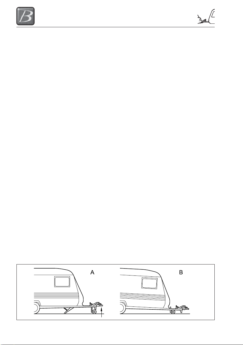
• The noseweight (A) may not exceed the
max. 150 kg.
• Make sure that the ground is sufficiently
even and that there are no holes and/
other obstructions present.
• Place the caravan on a firm footing,
otherwise the axle supports may sink into
the ground.
Note: It is important that when you use the
system the caravan is standing facing slightly
downhill (B).
• Never use the system when there is
anything attached to the caravan, such
as an awning or a canopy.
• Never use the levelsystem in automatic
mode when the caravan is attached to
the vehicle
The following safety precautions must be
observed when positioning the caravan.
• Apply the caravan handbrake securely.
• Make sure that when the system is being
operated, no-one is present in the vicinity
of the caravan.
• Do not use any additional supports
underneath the axle and corner supports.
• Place no blocks during either manual or
automatic levelling.
• Make sure that when levelling is being
carried out, on-one is in the caravan.
• An acoustic signal will be sounded during
the levelling process.
• The levelling program can be stopped at
any time by pressing the ON/OFF button
on the control panel or (optional) remote
control.
WARNING: Before driving off, check to
make sure that all supports have been
withdrawn.
Safety warnings
Not observing the following warnings may
lead to damages to the caravan and/or
serious physical injuries.
• Using the E&P hydraulics levelling
system for other purposes than
supporting the caravan is officially
forbidden according the E&P Hydraulics
Limited warranty.
• This product is exclusively developed as
a levelling system and may not be used
for other work under the caravan such as
changing the tyres.
• When the system is operating, all
persons and animals should keep their
distance.
• Body parts (e.g. hands and eyes) should
never come into contact with released
fluids. Oil leaving the hydraulic levelling
system may be under high pressure and
could cause serious injuries to the skin.
Consult a doctor immediately in case of
accidents.
• The caravan should be parked on a solid,
level and non-slippery surface. The
parking location must be free of holes of
waste and surrounding objects.
• If the caravan is parked on very soft soil,
you must place a support plate under
each jack in order to distribute the
weight.
• Check if the installation of the hydraulic
levelsystem is performed by a skilled
mechanic with sufficient practical
experience and technical E&P hydraulics
training.
5-2
ARRIVING ON SITE
• In case of repairs/malfunctions to the
hydraulic levelsystem: know what you are
doing. Never try to repair it yourself, but
consult your installer or dealer.
• Fully read this user manual, before using
the hydraulic levelling system.
• After deploying the hydraulic levelsystem
ALWAYS make an inspection tour around
the caravan. Just to be sure the caravan
stands stable (all hydraulic jacks are on
the ground).
Control functions
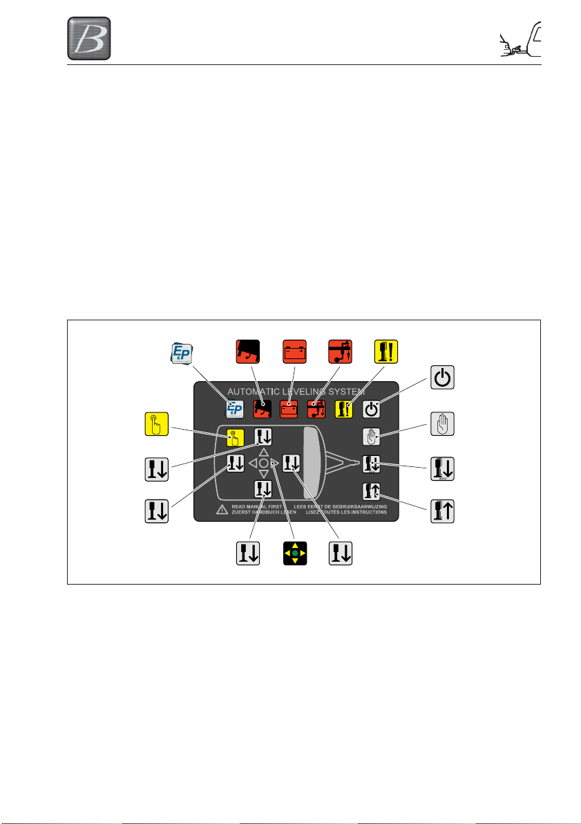
Functions on the control panel
The diagram below shows the appearance of the control panel. By using the control panel (or
remote control) you can operate the hydraulic levelsystem.
16
9
10
11
Function declaration:
(1) LED: Slope too steep
(2) LED: Battery low voltage
(3) LED: Withdraw front wheel
(4) LED: Jacks not (fully) retracted
(5) Button: ON/OFF
(6) Button: Manual mode
(7) Button: Automatic mode
(8) Button: Retract all Jacks
1
13
2
14
3
12
4
5
6
7
8
(9) LED: Manual mode
(10) Button: Left side
(11) Button: Rear side
(12) Button: Front side
(13) Button: Right side
(14) LED: Level indicator
(16) LED: E&P logo
5-3
ARRIVING ON SITE
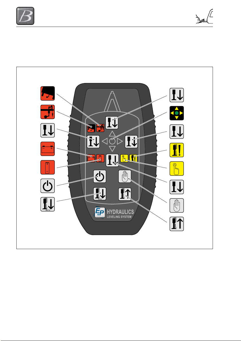
Functions
The diagram below shows the appearance of
the remote control. By using the remote
control you can operate the hydraulic
levelsystem.
1
3
10
2
15
5
7
12
14
13
4
9
11
6
8
Function declaration:
(1) LED: Slope too steep
(2) LED: Battery low voltage
(3) LED: Withdraw front wheel
(4) LED: Jacks not (fully) retracted
(5) Button: ON/OFF
(6) Button: Manual mode
(7) Button: Automatic mode
(8) Button: Retract all Jacks
(9) LED: Manual mode
(10) Button: Left side
(11) Button: Rear side
(12) Button: Front side
(13) Button: Right side
(14) LED: Level indicator
(15) LED: E&P logo
5-4
ARRIVING ON SITE
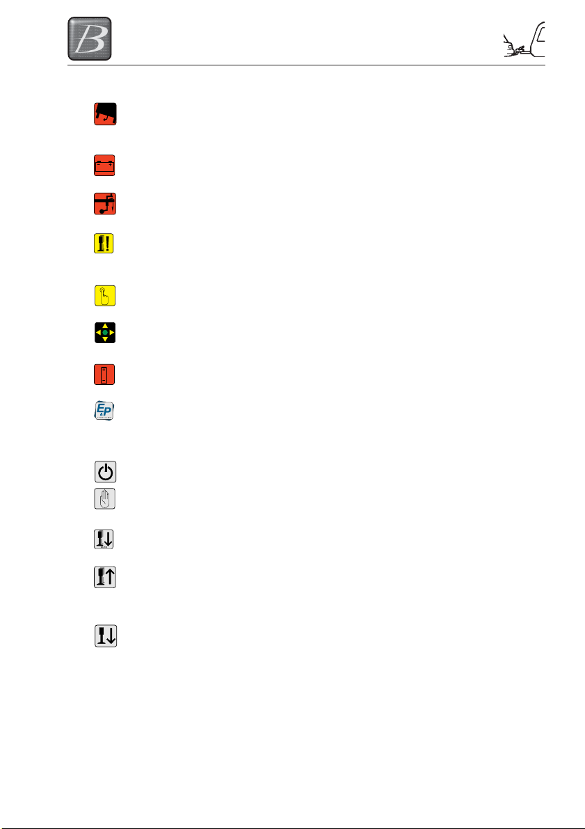
Extensive function declaration
(1) SLOPE TOO STEEP In this position the caravan cannot be levelled (the
(2) BATTERY LOW VOLTAGE The battery is empty of the voltage is too low to be
(3) WITHDRAW FRONT WHEEL The caravan is too high at the front, withdrawn the
(4) JACKS NOT (fully) One or more jacks are extended or not fully
RETRACTED
(9) MANUAL MODE Indicates that the caravan can now be brought to the
(14) LEVEL (zero point) Indicates that the caravan can now be brought to the
(15) BATTERY 9V VOLTAGE The battery voltage of the remote control is too low
(16) E&P LOGO Indicates that the levelsystem is switched on.
(5) ON/OFF Switches the levelsystem on or off.
(6) MANUAL MODE Switches the levelsystem into manual mode for
surface is not even enough) If necessary switch over
to manual mode.
able to work safely.
front wheel and the LED will go out.
retracted.
correct level manually.
correct level.
(only present on the remote control)
(only present on the remote control)
BUTTONS
levelling the caravan.
(7) AUTOMATIC MODE Switches the levelsystem into automatic mode for
AUTO
(8) RETRACT ALL JACKS Automatically retracts all jacks.
(10) LEFT SIDE Controls retracting and extending the left jacks.
(11) REAR SIDE Controls retracting and extending the rear jacks.
(12) FRONT SIDE Controls retracting and extending the front jacks.
(13) RIGHT SIDE Controls retracting and extending the right jacks.
levelling the caravan.
5-5
ARRIVING ON SITE
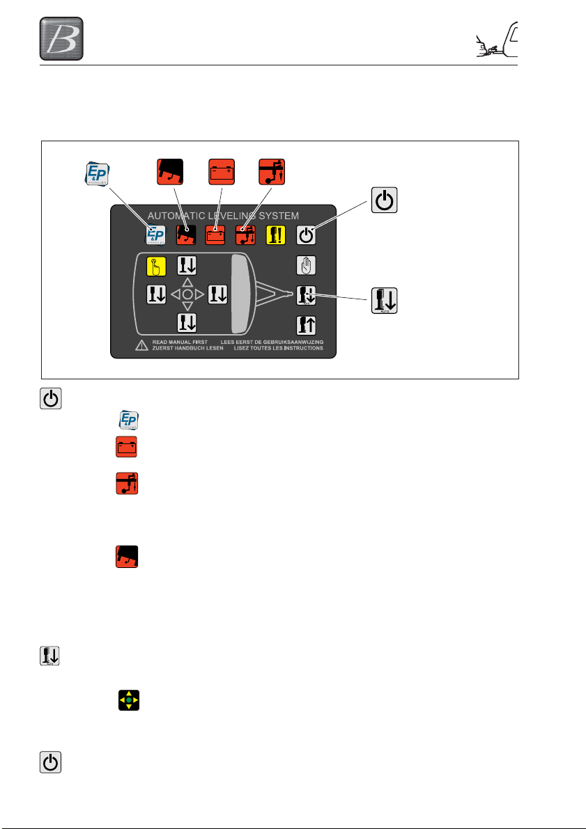
Operating the levelsystem
Automatic levelling
Procedure for automatic deployment/extension of the axle and corner supports.
1
2
Step 1 Press 1x on the button ON/OFF (no.5) to switch the levelsystem ON.
The E&P-logo LED lights up, indicating that the levelsystem is switched on.
When there is insufficient or no battery voltage, the indicator LED “LOW
VOLTAGE” (no.2) lights up.
In automatic levelling, the caravan must be tilted a few degrees forwards.
The system will indicate whether you have positioned the caravan level
enough. If you have not, the indicator LED “FRONT WHEEL” (no.3) lights
up and the system cannot be started automatically. The front wheel must be
wound down.
When the caravan leans too steeply, the indicator LED “SLOPE TOO
STEEP” (no.1) lights up.
REMARK: When the caravan stands too skewed, the caravan cannot be
automatically levelled. You now have two options: Stop the levelling
procedure and place the caravan on a flatter surface and start again with
automatic levelling procedure. Or go further with manual levelling
procedure.
Step 2 Press 1x on the button “AUTOMATIC MODE” (no.7) to start the automatic
AUTO
levelling procedure.
When the levelling procedure is complete, the indicator LED “LEVEL”
(no.14) lights up GREEN.
REMARK: Depending on the angle of the terrain and type of caravan, the
automatic levelling procedure takes about 1 minute.
Step 3 Press 1x on the button “ON/OFF” (no.5) to switch the levelsystem OFF.
3
ON/OFF
(no.5)
AUTOMATIC
MODE
(no.7)
5-6
ARRIVING ON SITE
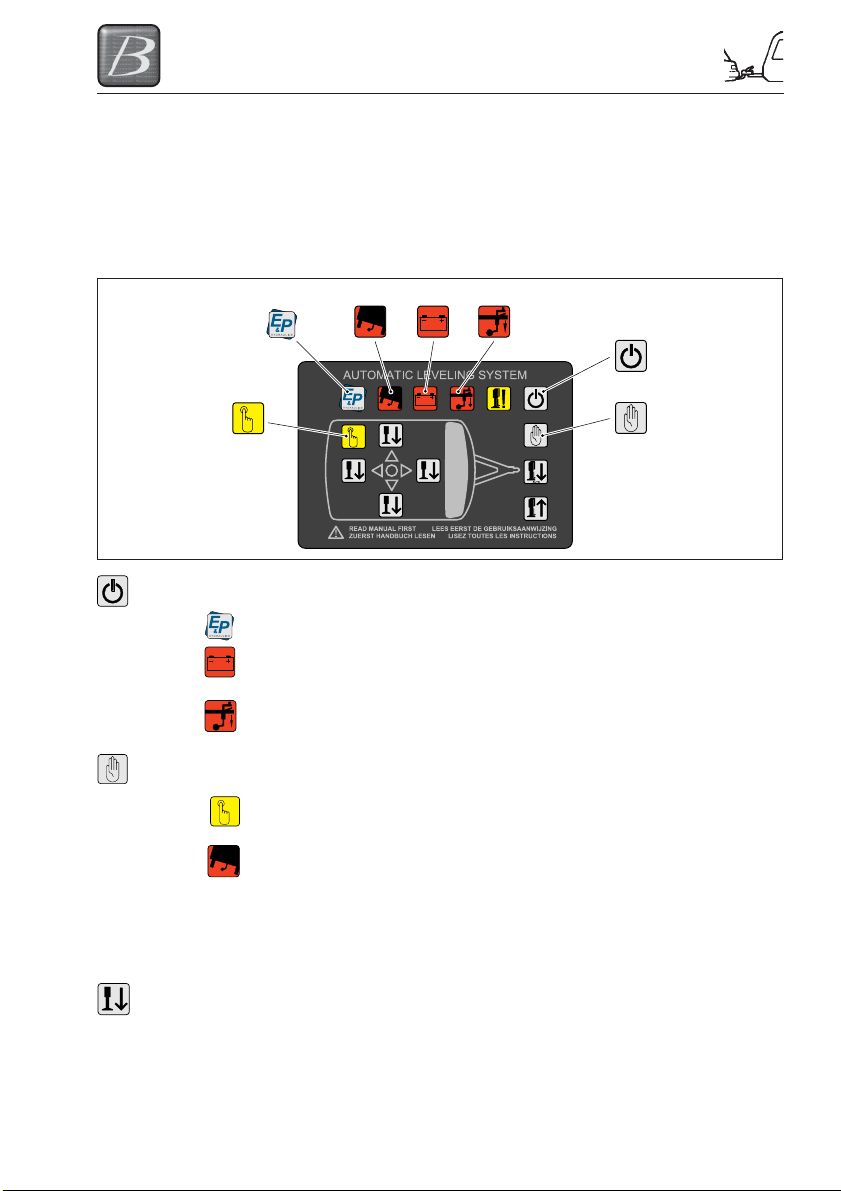
Manual levelling
In below the procedure for manual deployment/extension of the axle and corner supports.
The manual levelling function is mainly used when automatic levelling is not possible due to a
large tilt of the caravan. With the help of this feature it is also possible to change the position of
the caravan; think of your sleeping comfort. Most people prefer to sleep with their head up
slightly. Depending on the orientation of the caravan with this feature you can manually adjust
the angle where necessary.
12 3
ON/OFF
(no.5)
9
Step 1 Press 1x on the button ON/OFF (no.5) to switch the levelsystem ON.
The E&P-logo LED lights up, indicating that the levelsystem is switched on.
When there is insufficient or no battery voltage, the indicator LED “LOW
VOLTAGE” (no.2) lights up.
In manual levelling, the caravan must be tilted a few degrees forwards. The
system will indicate whether you have positioned the caravan level enough.
If you have not, the indicator LED “FRONT WHEEL” (no.3) lights up.
Step 2 Press 1x on the button “MANUAL MODE” (no.6).
The indicator LED “MANUAL MODE” (no.9) lights up, indicating the manual
levelling procedure may begin.
When the caravan leans too steeply, the indicator LED “SLOPE TOO
STEEP” (no.1) lights up, although this LED lights up, you are able to level.
On the side where the caravan is low, fill the space under the axle support
(footplate) with some boards to compensate the difference in height. This
will avoid the risk it is not possible to level the caravan due to a too large
difference in height. In case of too large height difference the hydraulic jacks
may come to the end of their stroke.
Step 3 In most common cases, there lights up one ORANGE arrow on the control
panel (no.14) which indicates on which side the caravan has to be lifted.
Before lifting this side, FIRST lower the other axle-support till it touches the
ground.
MANUAL
MODE
(no.6)
5-7
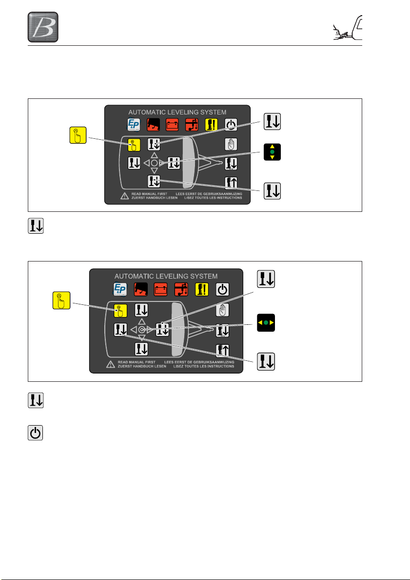
ARRIVING ON SITE
Then the other axle support can be extended by holding button “LEFT
SIDE” (no.10) or “RIGHT SIDE” (no.13) pressed down. The levelling
procedure automatically stops when the caravan is levelled in the left right
direction. The ORANGE arrow level LED (no.14) goes out.
9
Step 4 Press the button “FRONT SIDE” (no.12) and hold it pressed down till the
ORANGE arrow level LED (no.14) goes out, extending of the front corner
supports stops by itself when the caravan is levelled in the front to rear
direction.
9
LEFT SIDE
(no.10)
INDICATOR LED
(no.14)
RIGHT SIDE
(no.13)
FRONT SIDE
(no.12)
INDICATOR LED
(no.14)
REAR SIDE
(no.11)
Step 5 Press the button “REAR SIDE” (no.11) until the corner supports at the rear
Step 6 Press 1x on the button “ON/OFF” (no.5) to switch the levelsystem OFF.
side are touching the ground. Attention: The level system does NOT stop
automatically.
5-8
ARRIVING ON SITE
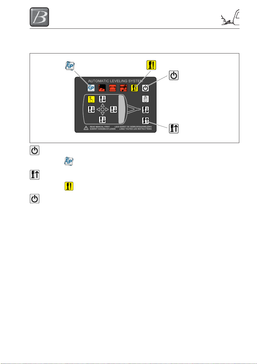
Retracting the jacks
Follow the procedure below to retract the axle and corner supports.
4
ON/OFF
(no.5)
RETRACT ALL
JACKS (no.8)
Step 1 Press 1x on the button “ON/OFF” (no.5) to switch the levelsystem ON.
The “E&P-logo” LED lights up, indicating that the levelsystem is switched
on.
Step 2 Press 1x on the button “RETRACT ALL JACKS” (no.8) once.
The indicator LED “JACKS NOT FULLY RETRACTED” (no.4) goes out
when all jacks have been fully retracted.
Step 3 Press 1x on the button “ON/OFF” (no.5) to switch the levelsystem OFF.
IMPORTANT: Before departure ensure all supports have been retracted.
Extra Extra
Extra functions
Extra Extra
Calibration (setting the zero point)
The calibration procedure described below has already been carried out at your dealer/installer.
You don’t have to perform this procedure by yourself. E&P Hydraulics has decided to include this
chapter as an extra in this manual in case of failure and/or service & repair matters.
Consider setting the zero point** as a condition to make it possible to level the caravan
automatically and/or manually. When this operation, for some reason, has not been done or has
been carried out incorrectly, it is not possible to level the caravan.
**The zero point is the point (level) at which the hydraulic levelling system (in an automatic cycle)
returns.
Start: Manual levelling
Before automatic levelling can be activated, you must set the zero point. For setting the zero
point, you must FIRST perform the manual levelling procedure.
REMARK: Do this by placing a spirit level in the centre of the caravan.
ATTENTION! Never put the rear brackets first to the ground. This in case creating too
much load on the caravan.
5-9
ARRIVING ON SITE
Setting the zero point
Step 1 Press 1x on the button “ON/OFF” (no.5) to switch OFF the levelsystem after manual
Step 2 Press 1x on the button “ON/OFF” (no.5) to switch the levelsystem ON.
Step 3 Press 5x on the button “FRONT SIDE” (no.12)
Step 4 Press 5x on the button “REAR SIDE” (no.11)
Step 5 Press 3x on the button “RETRACT ALL JACKS” (no.8)
Step 6 Press 1x on the button “ON/OFF” (no.5) to switch the levelsystem OFF.
Remote control (optional)
Preface
The procedure described below has already been carried out at your dealer/installer.
Consider programming (setting) the remote control as a condition to make it possible to level the
caravan automatically and/or manually. When this operation, for some reason, has not been
done or has been carried out incorrectly, it is not possible to level the caravan with the remote
control.
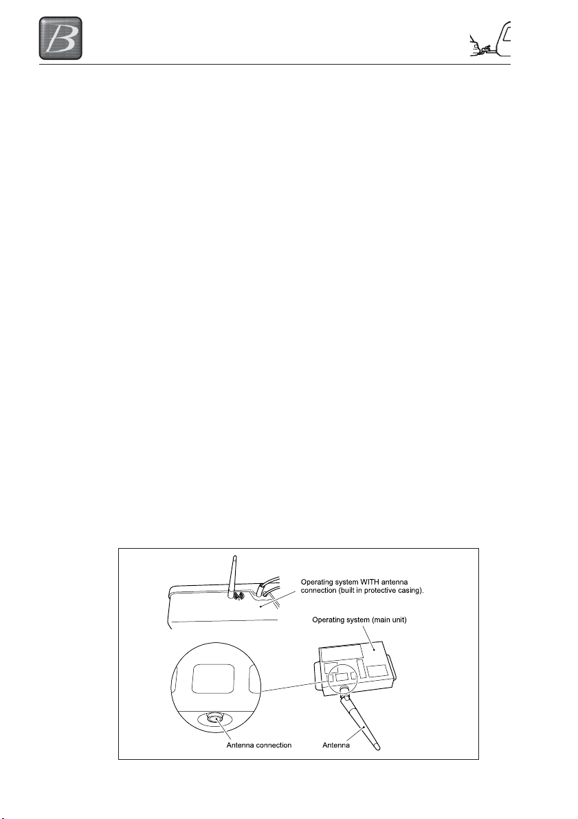
Antenna
Check if there is a antenna connection on the operating system (see below). If this is not the
case, the remote control CANNOT communicate with the hydraulic levelling system. In principle,
the antenna connector and the antenna are always present when you purchase the levelsystem
including a remote control unit.
If you purchased the remote control at a later stage, then you should remember that this antenna
connection on the operating system (main unit) could be missing.
The presence of the antenna is dependent on the acquisition period the of the levelsystem. After
2013, all operating systems have this antenna connector. In this case, the dealer/installer can
directly connect the antenna to the operating system (the antenna is supplied with the remote
control)
Operating system including the antenna connection
levelling.
All LED’s on the control panel light up. (the vehicle stands in zero mode)
The zero point is programmed.
5-10
ARRIVING ON SITE
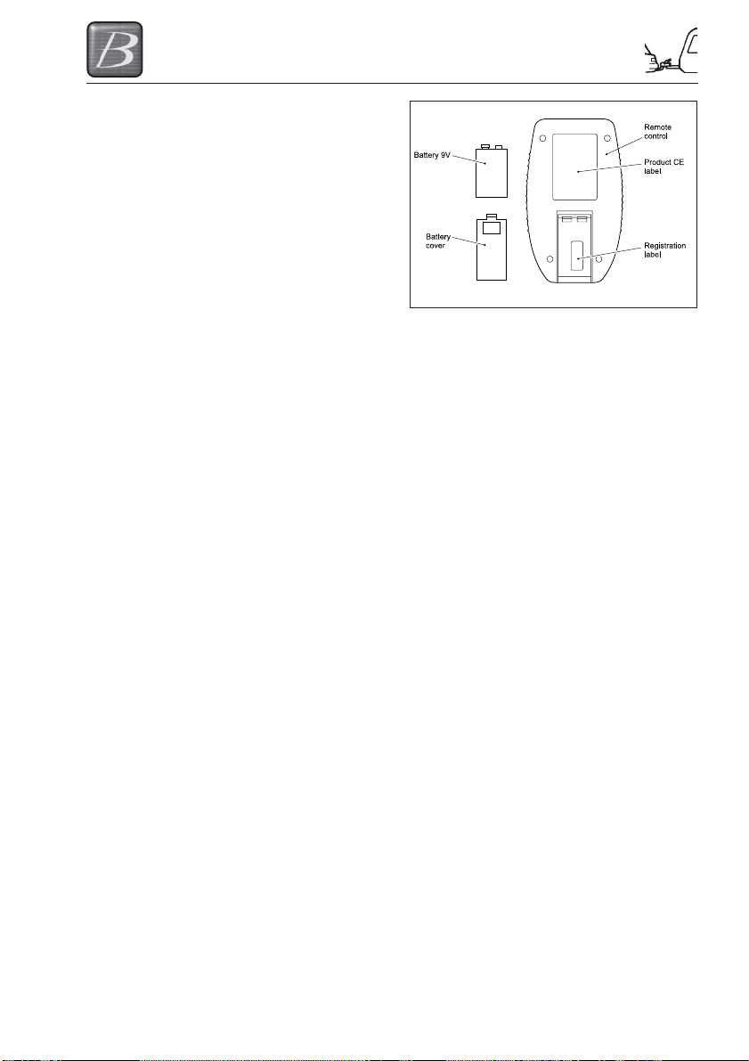
Battery
Remove the battery cover on the rear side of
the remote control by firmly pressing the
cover and then sliding out. Insert the 9V
battery carefully reassemble the battery
cover (in most common cases the battery is
already fitted).
Programming the remote control
Step 1 In order to pair the remote control to the system, remove the fuse (30 Amp) out of the
Step 2 Press the buttons “AUTOMATIC MODE” (no.7) and “RETRACT ALL JACKS” (no.8)
Step 3 Reconnect the fuse to the system.
Putting the remote control into use
After programming the remote control you now have the possibility to operate the levelsystem
with the remote control.
Step 1 Switch the remote control ON by pressing button “ON/OFF” (no.5) for at least 1
cable assembly from the hydraulic levelsystem.
simultaneously.
When done, the Indicator LED (no.14) with the surrounding 4 arrows starts blinking
GREEN/ORANGE rapidly. This means the remote control is looking for its receiver,
mounted within the operating system.
- The pairing process should be made within a certain time (approx. 20 sec)
- The remote control turns off automatically.
- When the Indicator LED (no.14) goes off, the pairing process is complete.
second.
Now the GREEN LED will light up by flashing. As long as you see this LED flashing,
the remote control is searching for contact with the operating system. When contact
is made the flashing stops.
The illumination of one or two ORANGE arrows on the indicator LED (no.14) central
on the control panel shows the position of the caravan.
In the unlikely event that the caravan is already level, then the indicator LED (no.14)
lights up GREEN.
5-11
 Loading...