


Instruction Manual 116/GB - PN. 991198 DOC. TEC.
INSTRUCTION MANUAL
MUX 2700
M U LT I P L E X E R
FOR MORE INFORMATIONS, VISIT THE DEDICATED HiS WEB SITE: www.elconhis.com

IM-ENG-116/GB
TABLE OF CONTENTS
1. INTRODUCTION ................................................................................................. page 2
2. UNPACKING AND STORAGE ............................................................................ “ 3
3. FUNCTIONAL DESCRIPTION ............................................................................ “ 4
3.1 Overview .................................................................................................... “ 4
3.2 Operation ................................................................................................... “ 6
3.3 LED indications ......................................................................................... “ 6
3.4 Power-up sequence ................................................................................... “ 6
3.5 Application guidelines ................................................................................ “ 7
3.6 Hardware architecture ................................................................................ “ 7
3.7 Software architecture ................................................................................. “ 8
4. HART INTERFACE SOLUTIONS OVERVIEW .................................................. “ 9
4.1 Presentation ............................................................................................... “ 9
4.2 1132/CON solution .................................................................................... “ 10
4.3 2108/64 HART D solution .......................................................................... “ 11
4.4 I.S. Integrated solutions (MUX2700 with HiD2000 Intrinsic Safety interfaces) .. “ 12
4.5 Electrical connections ................................................................................. “ 12
5. MAINTENANCE WORKSTATION OVERVIEW.................................................... “ 13
5.1 General ...................................................................................................... “ 13
5.2 Software packages .................................................................................... “ 13
6. MUX 2700 SPECIFICATIONS .......................................................................... “ 14
6.1 General ...................................................................................................... “ 14
6.2 Mechanical ................................................................................................. “ 14
6.3 Supply port ................................................................................................. “ 15
6.4 Signal port (HART) ..................................................................................... “ 15
6.5 Serial Port (RS-485) ................................................................................... “ 15
7. INSTALLATION AND CONFIGURATION ............................................................. “ 17
7.1 Operating environment .............................................................................. “ 17
7.2 DIP-switch configuration ............................................................................ “ 17
7.3 Connections and mounting ........................................................................ “ 19
7.4 Final checks ............................................................................................... “ 19
8. MAINTENANCE AND TROUBLESHOOTING ...................................................... “ 21
8.1 Maintenance .............................................................................................. “ 21
8.2 Off-line self-test procedure ......................................................................... “ 21
8.3 Additional troubleshooting .......................................................................... “ 21
9. QUALITY MANAGEMENT POLICY.................................................................... “ 22
10. WARRANTY..................................................................................................... “ 23
11. ACRONYSM .................................................................................................... “ 24
12. APPENDIX A: MUX 2700 ISOLATION STRUCTURE ................................... “ 25
FOR MORE INFORMATIONS, VISIT THE DEDICATED HiS WEB SITE: www.elconhis.com
WARNING!
This manual is copyright by Elcon Instruments. All rights reserved. No part of manual may be reproduced in part or in
whole without express written consent from Elcon Instruments. Elcon Instruments reserves the right to modify manual
or any part thereof at its discretion without prior notice.
- 1 -

IM-ENG-116/GB
1. INTRODUCTION
This manual is intended to provide guidance for the installation, operation and maintenance of the Mux2700 HART
Signal Multiplexer (HSM) module. To avoid damage, failure or improper operation the contents of this manual
should be read and understood before installing and operating the instrument.
The Mux2700 HSM is a compact, plug-in module which is able to accept up to 32 HART channels and to feed them
into a single, faster communication line, which is in turn to be connected to a suitable Maintenance Workstation.
The Mux2700 module is intended for use as part of the Elcon HART Interface Solutions (H.I.S.), which provides
appropriate interconnection packages for various applications. H.I.S. makes available a wide set of Termination
Boards – with or without integrated isolators – to support different applications and to directly interface with the
main PLC/DCS equipment. The Mux2700 is simply to be inserted in the selected board to get full HART access to
the relevant field devices while preserving the traditional 4/20 mA analogue loop interfaces.
The Mux2700 use the same effective and compact enclosure of the successful HiD series, including the innovative
“Quick Lock” mechanism to easily insert/remove the unit from the Termination Board without the need for any tool.
Key features summary:
• low power consumption , very small size;
• compact and proven HiD enclosure, “Quick Lock” capability;
• high noise immunity, industrial-level EMC compliance;
• two DC-blocking capacitors – non-polarised type – on each signal loop;
• optimal mechanical integration with other HiD solutions;
• fully compatible with existing MUX 1700 solutions;
• very low loop-interference risk (TUV fail-safe approval pending).
Warning !
The Mux2700 module is not certified for intrinsically safe applications and must not be used to directly interface
with hazardous-area located field devices. However, some H.I.S. solutions do allow the mounting of the Mux2700
on the same board where intrinsically safe isolators are located. In this case, the safety-related application areas
must be addressed by trained personnel which is fully acquainted with the principles of intrinsically safe system.
Elcon Instruments has published a complete tutorial entitled “Guide to Intrinsic Safety” covering most aspect of
intrinsic safety. The book can be obtained from Elcon Instruments free of charge.
- 2 -

IM-ENG-116/GB
2. UNPACKING AND STORAGE
Upon receipt of the materials, you should immediately check the integrity of both packaging and contents. In case
of damage due to shipping, the receiver should promptly and properly report to the shipper supplying all necessary
information.
If the instruments are not for immediate use, a check is recommended about the compliance of the units specifications (as indicated on the label) with both order specifications and with the actual application requirements.
In case of storage of instruments and accessories, proper care should be taken to protect them from any possible
damage. Always store instruments in their sealed original packaging until they are installed. In addition, adequate
protection should be provided from:
• humidity and temperature excursions outside the specified range;
• aggressive or polluting atmospheres (e.g. SO2, H2S, mists, salts, smokes, dusts);
• access by insects/rodents that could damage packaging or content;
• mechanical shocks or intense vibrations.
- 3 -

IM-ENG-116/GB
3. FUNCTIONAL DESCRIPTION
3.1 Overview
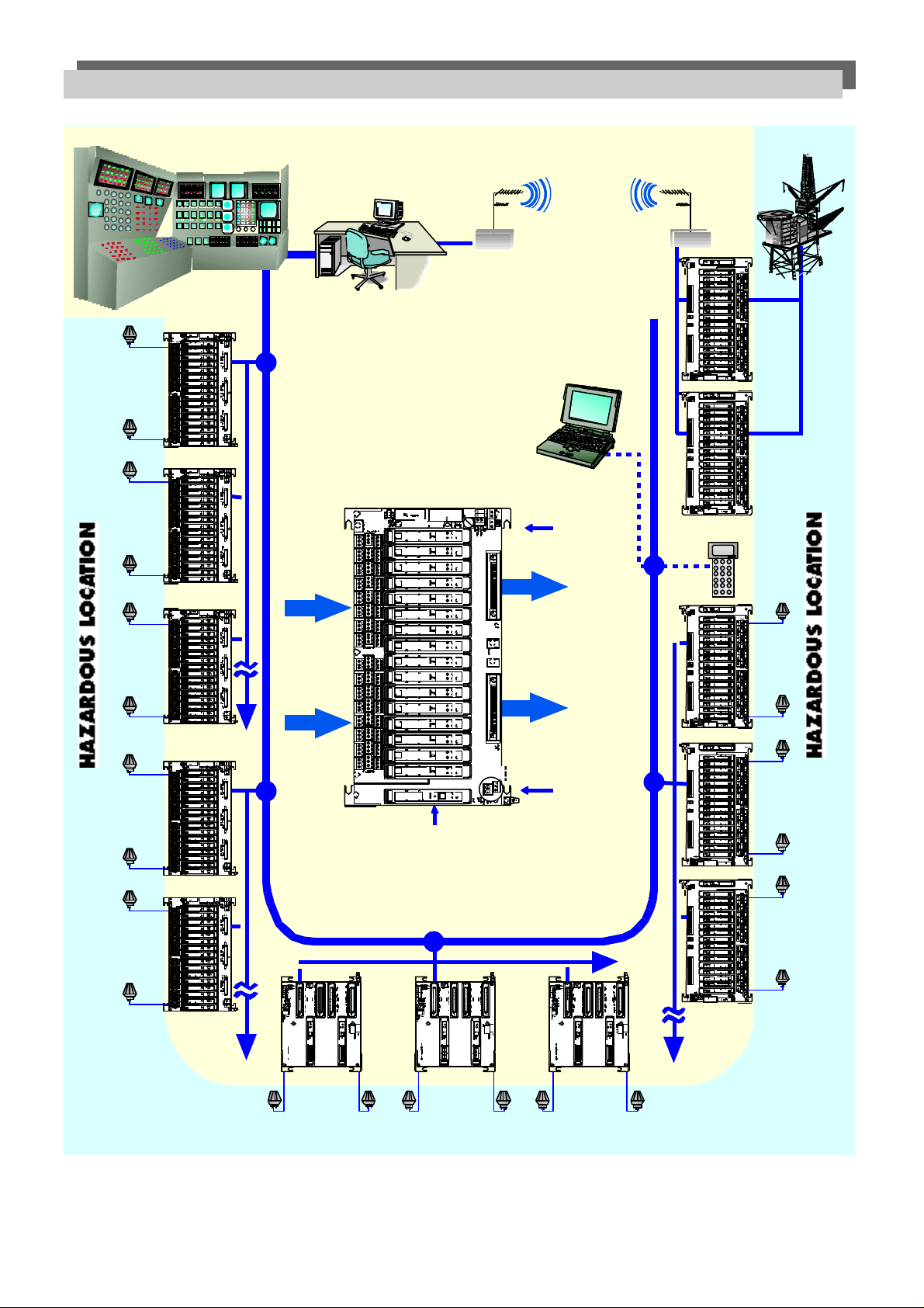
The Mux2700 HART Signal Multiplexer (HSM) provides 32 signal channels for connection to field located, “smart”
transmitters or control devices supporting digital communication according to the HART standard. The Mux2700
acts as a gateway between a Maintenance Workstation (MW) – typically a PC with suitable SW – and the field
instrumentation. The MW connects, in a multi-point configuration, with up to 31 Mux2700 using a fast RS-485 communication channel.
The HART protocol is a widely accepted technique by which standard 4/20 mA field devices can support digital
communication for configuration and maintenance purposes. A modulated, audio-frequency signal (Bell202 FSK) is
in fact superimposed to the analogue current loop providing a 1200 baud, half-duplex communication capability.
The HART protocol, being a widely accepted standard specified up to the application layer, permits an effective
integration, at the Maintenance Workstation level, of field devices from different manufacturers.
The Mux2700 HSM not only uses the HART protocol to communicate with the field devices but also to interface
with the Maintenance Workstation via an RS-485 link. In this way, an highly standardised solution is obtained.
Under the supervision of the Maintenance Workstation, the Mux2700 interrogates each field device, retrieving information which are then stored in an internal data-base. This internal data-base can then be accessed in real-time by
the MW which however, when required, can also directly communicate with any specific field device.
- 4 -
IM-ENG-116/GB
1
up
to
32
1
up
to
32
1
up
to
32
To
DCS - PLC I/O
CARDS
(To Control Room)
TERMINATION BOARD
RS 485
FROM
FIELD
DEVICES
SUPPLY
1
up
to
32
1
up
to
32
1
up
to
32
1
up
to
32
DCS/SCADA SYSTEM
1
up
to
32
1
ZONE 1
II C
up
to
32
CONTROL ROOM
(Hart or Non Hart
Compatible)
Model
2116/HAT/
Model
2116/HAT/
RADIO MODEM
UHF Microwave
P.C. MAINTENANCE WORKSTATION
NON HAZARDOUS LOCATION
PCU # 1
CATALYTIC CRACKER
PORTABLE
NOTEBOOK
or LAPTOP
Model
2116/HAT/
RADIO
MODEM
HHC
Remote instrument
maintenance
monitoring for
unmanned
platform or
remote site
ZONE 1
II C
32
32
32
32
up
up
up
up
Model
1
1
2116/HAT/
to
to
To Further
Boards
Model
1
to
1
to
2116/HAT/
Model
2116/HAT/
PCU # 2
BOILER
• Hazardous Non Hazardous Locations of Smart Instruments
• Local or Remote Instruments Maintenance
• Suitable for Existing Smart Field Device Transmitter, Valves, Mas Flow
• Multiple
• Independent to DCS System
• ISO 9000 Reporting
MUX 2700
PCU # 3 REFORMER
TANK
FARM
To Further
Boards
ZONE 2
II B
To Further
Boards
MUX
MUX
MUX
2700
2700
MUX
2700
2700
MUX
2700
1 up to 32 1 up to 32 1 up to 32
NON HAZARDOUS LOCATION
MUX
2700
ZONE 1
II B
To Further
Boards
FIG. 1
- 5 -
IM-ENG-116/GB
3.2 Operation
The Mux2700 HSM module implements HART protocol commands and acts as a gateway device between the
Maintenance Workstation (MW) and the field devices. It responds to commands received from the MW (RS-485
interface) as a slave device and issues commands to the HART slaves (field channels) acting as either a Primary
or Secondary Master (according to the HART specification).
A modified version of the HART protocol was implemented on the RS-485 physical layer to obtain a fast and reliable communication with the Maintenance Workstation. In this way, standard HART messages can be used by the
MW for an effective, seamless integration of field devices from different manufacturers.
The Mux2700 can continuously poll each connected field device the get the specified primary (or secondary) HART
variable, automatically updating the internal data-base. This is called scan operation, and can be enabled or disabled by the Maintenance Workstation (the Mux are factory set in the “Scan-Off” condition). When in the “Scan-On”
mode, the MW can generate a warning message whenever a field device stop communicating (e.g. because it is
disconnected from the loop).
At power-up, the Mux2700 always performs a locate activity, that is to say, it polls all the 32 channels to find any
connected – and communicating – field device and to rebuild the required, internal access tables. The locate activity can be started also by the Maintenance Workstation, and this is usually required to be able to communicate
with a new field device connected to the Mux after power-up. The locate time can range from 15 to 60 seconds,
depending on the specified retry counts (the Mux are factory set with a retry count = 3, resulting in around one
minute of locate time).
In addition to providing access to the HART-capable field instruments, the Mux2700 module is itself, in all respect,
an HART device with parameters and internal functions available to the user (e.g. Tag, Description and unique DIN
– Device Identification Number).
3.3 LED indications
The information provided by the Mux 2700 LED (mounted at the panel front) is summarised in the following table:
Colour Name Function
Yellow HART TX ongoing HART communication with field devices
Green PWR ON supply indicator (can blink at power-up)
Red FAULT internal fault indication (power-up detection only)
3.4 Power-up sequence
In the following, the normal Mux 2700 power-up sequence is described. This is always the standard power-up
behaviour, unless SW8 (at the panel front) is set into the Test position.
• Immediately after power-up, the Green LED goes immediately On.
• An internal self-test is then performed and, if any problem is detected, the Red LED goes fixed On (on some
Mux versions, the Green LED could blink during self-test).
• The Yellow LED then start blinking, indicating that the Mux 2700 is performing the locate activity, that can last
up to around one minute (N.B. when the field multi-drop option is available and active, the locate time could be
up to15 minutes).
• The Yellow LED should then go Off, unless the scan operation is enabled or the Maintenance Workstation is
directly communicating with a field device.
- 6 -
IM-ENG-116/GB
3.5 Application guidelines
The Mux2700 HSM is not normally intended to be designed by the user in a specific application, but to be used as
part of the Elcon HART Interface Solutions (H.I.S.) offering, which provides appropriate interconnection packages
for a wide range of applications, as well as a set of compatible Maintenance Workstation solutions. This makes the
Mux2700 application straightforward, because most “tricky” interface and compatibility issues have already been
solved, and a ready to use, plug-and-play solution can be provided.
As an example, when “HART filters” are required to ensure the compatibility with a specific PLC/DCS, these are
usually directly integrated at the H.I.S. level.
However, there can be situations, as with “general-purpose”, screw-terminals H.I.S. boards, in which some care in
wiring and installation is required to set-up a working system. An overview of some H.I.S. solutions is presented in
section 4., please also refer to the relevant H.I.S. documentation for more information.
As a general guideline, it is worth noting that the Mux2700 input channels must be connected across the 4/20 mA
loop in such a way as to see parallel resistance not lower than 200 Ω (250 Ω recommended). If this is not the case,
the available HART signal could be too week to guarantee a reliable communication. A problem of this type can be
found with an analogue-input card with a low internal current-sense resistor, or with any loop-connected device
that, in spite of having an high DC resistance, presents too low an impedance on the 4/20 mA loop at HART frequencies (1200 / 2200 Hz).
In addition, it is always recommended to connect the “+” input terminal at higher DC voltage level with respect to
the “–“ input terminal (that will be in many cases at a GND level).
3.6 Hardware architecture
The heart of the Mux2700 HSM module is the microprocessor (CPU). One CPU serial port – together with the
HART modem and the related analogue circuits – implements the physical layer of the HART protocol. A second
CPU serial port is used to drive the opto-isolated RS-485 interface.
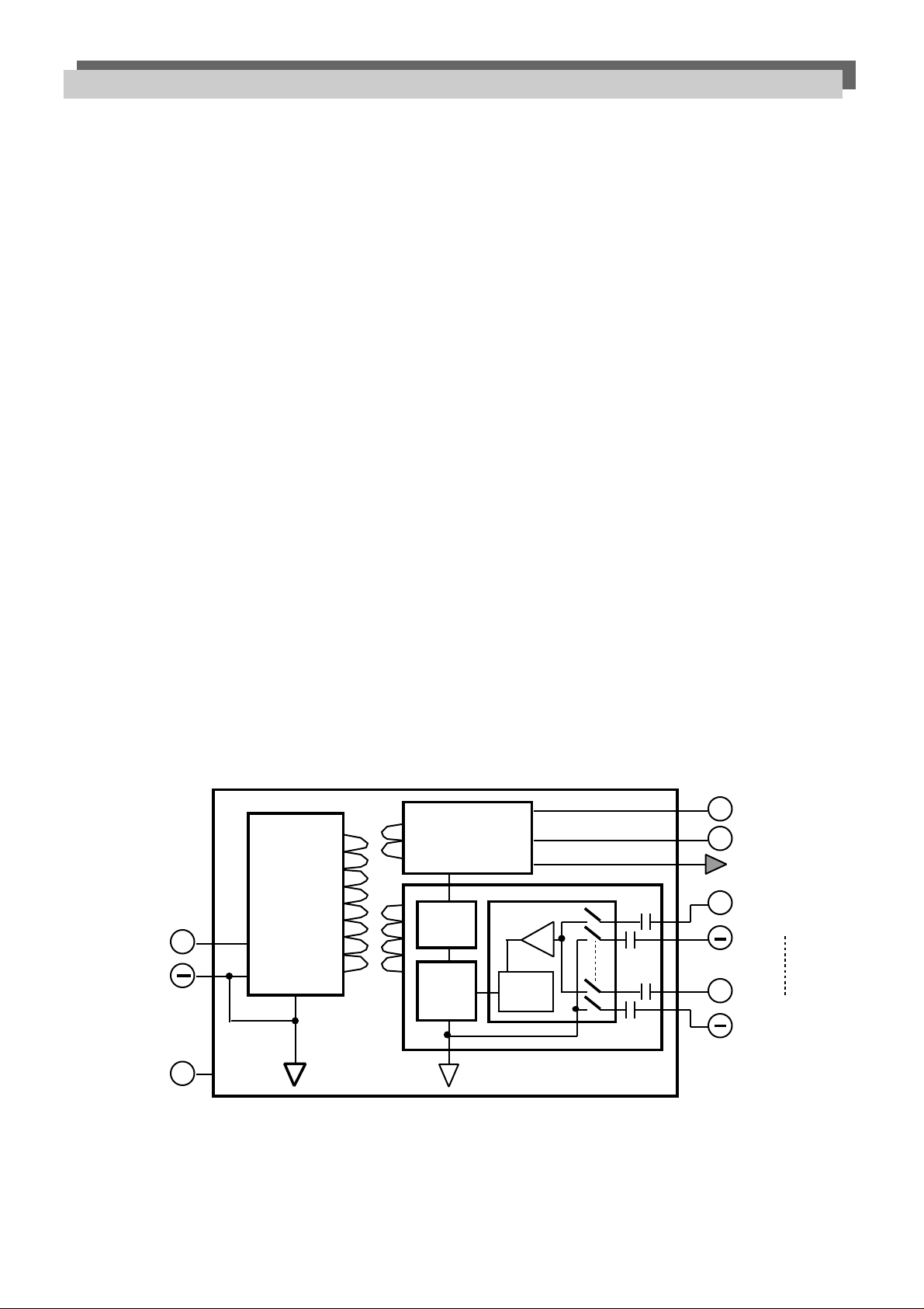
The internal architecture of the Mux2700 Multiplexer is depicted in the following block diagram of Fig. 2. As you can
see, the HART modem is multiplexed on the 32 available field channels to get a cost-effective and compact solution.
A
A31
24V
A1
+
A3
SCREEN
POWER
SUPPLY
UNIT
RS-485
INTERFACE
OPTO
ISOL.
CPU
MUX
HART
MODEM
0.68µF
A
2.2µF
0.68µF
2.2µF
+
+
A30B
A32
C32
CH1
B32
C1
CH32
B1
A4,A5,A6
FIG. 2
- 7 -

IM-ENG-116/GB
A full three-port isolation is also provided. The power supply section is in fact galvanically isolated from both the
analogue multiplexing section and from the RS-485 serial line.
Each input channel is also DC-isolated from the input GND by two non-polarised capacitors. The dual capacitor
solution, usually not to be found on comparable products, avoid the need of having a single common ground for all
input signals. In this way, it is also possible to connect to any “floating” loop without any loss of isolation
In general, the three-port isolation combined with the dual-capacitor approach result in an effective and reliable
solution, with such advantages as:
• undesired ground loops can be easily avoided;
• existing isolation between different ports can be preserved;
• very low risk of disturbing the 4/20 mA loop signal, also in case of fault.
I fact, the Mux2700 architecture is such that any internal single fault never result in any interference with an input
connected 4/20 mA loop. For this reason, the MUX 2700 can be used as a monitoring device within safety-sensitive
applications.
3.7 Software architecture
The Mux2700 HSM is not normally intended to be designed by the user in a specific application, but to be used as
part of the Elcon HART Interface Solutions (H.I.S.) offering, which includes a set of compatible Maintenance
Workstation solutions.
This means that the user doesn’t have to worry about either the internal details of the unit software functions nor
about the specific RS-485 protocol features. In fact, the Maintenance Workstation software make most of these
details “invisible” to user by providing an user-friendly, graphical man-machine interface.
When you have any special need or problem, please contact Elcon for additional information.
- 8 -

IM-ENG-116/GB
4. HART INTERFACE SOLUTIONS OVERVIEW
4.1 Presentation
HART Interface Solutions (H.I.S.) makes available a wide set of Termination Boards to support different applications. There are several styles of interconnection methods available for mounting of the Mux2700 to suit the various
demands of particular installations.These satisfy the basic requirements of:
• general purpose wiring interconnection;
• replacing the function of existing control system termination panels;
• including Intrinsic Safety isolating interfaces.
The details of specific applications can be found in the support documentation for the HART Interface Solutions
(H.I.S.) panels which are custom designed to satisfy these particular needs.
However, the following sections give details of three generic solutions for the mounting of the Mux2700 which are
included to show the scope of these possibilities:
• single Mux2700 mounting on termination panel: 1132/CON-8-H-DS
• multiple Mux2700 mounting on termination panel: 2108/64-HART-D
• Mux2700 integrated with HiD 2000 IS interfaces: 2116/HAT/SACON-HART
- 9 -

IM-ENG-116/GB
JP (1 to 31)
or FUSE
JA
(1 to 32)
JB
(1 to 32)
JP (2 to 32)
or FUSE
4.2 1132/CON solution
281 mm
I.A.C. (INTERFACE ADAPTOR
CARDS CAPABILITY)
DC
SUPPLY
TERMINALS
COMMON
SHD
SHD
SHD
1
2
SPARE
FUSE
RS 485
GND
Bolt
255.5 mm
FIELD CONNECTION
TERMINALS
Selecting Different Input Connections Arrangements
1) LOOP SUPPLY TRANSMITTERS (non individually fused 3) 4-20mA FROM FIELD
inputs) - Install JPA on position 3
- Install jumper JP - Install JPB on position 1
- Install jumper JPA and JPB on position 3 - Connect 4-20mA inputs at terminals
- Connect Tx at terminals +24V (positive) and C (negative) C (positive) and B (negative)
For individually fused loop supply Tx plug TR5 50mA value
fuses in place of JP jumpers (connections remains the same) 4) I/P SMART
- Install JPA on position 1
2) 1-5V FROM FIELD - Install JPB on position 1
- Install JPA and JPB on position 1 - Connect I/P at terminal C (positive) and
- Connect inputs at terminals C (positive) and B (negative) B (negative)
FIG. 3
- 10 -

IM-ENG-116/GB
4.3 2108/64 HART D solution
Elcon I.S. Termination Panel
with pick-off for HART signals (example)
16 channels
16 channels
16 channels
16 channels
24 Vdc
To RS485/RS232
converter
T.B. type 2108/64 HART D
(total 64 ch.)
FIG. 4
General purpose
1-5 V HART signal inputs
(PHOENIX VARIOFACE style)
- 11 -

IM-ENG-116/GB
4.4 I.S. Integrated solutions (MUX 2700 with HiD2000 Intrinsic Safety interfaces)
I.S. FIELD TRANSMITTERS
AND VALVES
FIG. 5A
FIG. 5B
HAZARDOUS AREA
Field
IN Ch. 1
IN
Ch. 2
on Board MUX2700 (up to 32 ch.)
LOOP DIAGRAM (Example of an I.S. integrated solution)
Intrinsic Safety & Termination Cabinet
24 Vdc
24 Vdc
+ 1
4
+ 2
5
HiD 2026
SAFE AREA
PS1+
PS2+
~
~
~
~
MUX 2700
F
F
F
DC
Supply
Bus
+11
14
+12
15
+
to DC
Supply
Bus
Multiplexer
GND
A
B
RS485
(duplicated)
1-5 Volts
J10
DCS I/O
CL 6825
16 AI
4.5 Electrical connections
All H.I.S. electrical connections and wiring should comply with the standards and installation rules (e.g. ISA
RP12.6) applicable in the country of use.
Before powering the Termination Board, verify the polarity and the voltage level of the supply line. The supply voltage must be within the limits specified for the Mux 2700 module.
Warning !
Improper supply connections could seriously damage the Mux 2700 module.
- 12 -

IM-ENG-116/GB
5. MAINTENANCE WORKSTATION OVERVIEW
5.1 General
A Maintenance Workstation (MW) is to be connected to the installed multiplexers to implement the required, HARTrelated configuration and supervision activities. In fact, the Mux2700 basically acts as a gateway between the field
devices and the MW.
The Maintenance Workstation is typically made of a suitable software package loaded on a standard desktop PC
equipped within external RS-232/RS-485 converter. The recommended operating system is Windows NT, but
Windows98/95 is also generally supported. As for required PC features, please refer to the documentation of the
applicable MW software package.
At least one free serial communication line (RS-232) must be available on the Maintenance Workstation to connect
the 232/485 converter. Most MW software packages generally permit the usage of more than one serial line (with
additional 232/485 converters) to increase the total number of accessible field devices.
Up to 31 Mux2700 modules can be connected to a single RS-485 serial line, for a total of 992 accessible field devices. The Maintenance Workstation is usually able to support more serial lines, so it is possible to effectively manage a few thousands of field devices without problems.
The recommended RS-232/RS-485 converter is the MD44 model (Westermo). Other equivalent devices can be
found on the market (e.g. from Keithley) but it is better to check their compatibility with the specific Maintenance
Workstation software.
5.2 Software packages
Several PC software packages are available which include support for the Elcon Mux2700 HSM.
Asset Management Solutions (AMS) from Fisher Rosemount, (www.frco.com/fr/solutions/ams) is a scalable softwa-
re product with full HART abilities, and functionality can be added as required. The “engine” of AMS is the Field
Server which provides access to HART information from any device with a common user interface and supports a
common database. The Universal System Interface is the software driver for an online link from the Field Server to
the Elcon Mux2700. Additional “snap-on” application packages are available for configuration, calibration, maintenance, valve diagnostics etc. to suit customer needs.
Valvelink from Fisher Controls (www.fisher.com) provides an easy-to-use environment for configuring, calibrating
and diagnosing the operating characteristics of Fisher Fieldview instruments such as valve controllers and transducers.
Applied System Technologies Cornerstone family of products is a comprehensive package useful for commissioning, calibration and maintenance management of industrial instruments both in the lab and in the field.
Cornerstone products provide multi-vendor support for all types of HART compatible smart instruments.
Cornerstone creates and maintains a comprehensive instrument database and individual histories of the configuration, test, calibration and maintenance activities performed on each instrument.
Finally, Field Browser from Neles Automation is another package which can directly interface with the Elcon
Mux2700 HSM.
For details about these software packages please refer directly to the supplier mentioned.
- 13 -

IM-ENG-116/GB
6. MUX 2700 SPECIFICATIONS
N.B.: all values are typical unless otherwise specified.
6.1 General
Operating Temperature: 0 to 55 °C (32 to 131 °F)
Storage temperature: -20 to 70 °C (-4 to 158 °F)
Relative humidity (non condensing): 5 to 90 %
EMC: EN50081-2, EN50082-2
Isolation (Supply port to Signal port): 1400 Vac, rms
Isolation (Supply port to Serial port): 1400 Vac, rms
Isolation (Serial port to Signal port): 500 Vac, rms
CE marking carried
6.2 Mechanical
Dimensions: see drawing
Case: HiD style, Policarbonate
Mounting: plug-in on Termination Board (no tool required)
Protection class: IP30
Connectors: 2, plug-in, 40-poles miniature connectors
Hot-plug in: supported
Unit weight: about 140 grams
- 14 -

IM-ENG-116/GB
6.3 Supply port
Supply voltage: 24 Vdc (-15%, +25%)
Supply current: 20 Vdc 32 mA (typical, RS485 quiescent)
24 Vdc 28 mA (typical, RS485 quiescent)
30 Vdc 23 mA (typical, RS485 quiescent)
Protection: internal fuse, not user-serviceable
6.4 Signal port (HART)
Channel number: 32 signal loops
DC-isolation: dual-capacitor isolation on each loop
Allowed common mode voltage: up to 30V
Differential mode clamping: +/- 5.2V (for transient or AC signals)
Receive signal range: 0.12 Vpp < signal < 1,5 Vpp
Receive impedance magnitude: > 5000 Ω
Carrier Detect levels: signal > 0.12 Vpp — CD asserted
signal < 0.080 Vpp — CD not asserted
Transmit signal amplitude : 200 mV (200 Ω load, typical)
500 mV (500 Ω load, typical)
200 Ω load — 150 mV < signal < 250 mV
Carrier stop time < 10 bit time
Device connection type: DC-isolated bus device
Impedance level type: High Impedance device
Data link type: Primary or Secondary Master (configurable)
Field multi-drop support: available on request
For additional, more detailed HART-related specifications, please refer to the HART FSK Physical Layer
Specification Rev.8.0 available from the HART Communication Foundation (HCF_SPEC-54), which the Mux 2700
module is generally compliant with.
Notes :
• To minimise input capacitors size and to get an higher output signal level, the Hart signal transmit section is based
on a current generation technique. For this reasons, the output signal level is proportional to the external load,
which should not exceed 500 Ω to avoid possible cross-talk or saturation problems.
• The specified transmit-signal amplitude is a DC value measured at the centre of a waveform semi-period.
• To maximise allowed cable length and to avoid noise problems, you should avoid to connect to the MUX HART
low impedence devices < 250 Ω.
6.5 Serial port (RS-485)
Line type: RS-485, differential pair plus GND
Line speed: 9600 Baud or 19200 Baud
Line topology: multi-point, master-slave connection
Device type: slave (up to 31 slave Mux can connected to a single master)
Slave addressing range: 1 to 31 (0 reserved)
Protocol type: H-Port (HART based)
Master device: Maintenance Workstation (MW)
Warning !
A suitable RS-232 to RS-485 converter is required to connect the port with a standard PC (see Fig. 6).
As for RS-485 line detailed specifications, please refer to the relevant standard.
- 15 -

IM-ENG-116/GB
SHD
1
SHD
SPARE
FUSE
2
RS-485
Connections
RS 485
GND
B
A
WESTERMO switch settings
to DCS
HART
PROTOCOL
AND 4-20mA
to DCS
See the Westermo Mod. MD-44 DC
instruction manual for details
Selection of data rate
Selection of bits
(8 bits odd parity - 1 stop bit)
Transmission
Termination
19200/9600
11
2-wire
No termination
switch bit
S2
1-2-3
S2
S2
S3
1-2-3-4
4-5
6-7
RS-485
Connections
Supply Line
Cord
RS-485
Connections
RS-232 INRS-485 IN RS-485 OUT
54321
9876
A
to PC
HOST STATION
B
GND
GND
B
A
CABLE PIN
ASSIGNMENT
Female DB9
connector
Pin No.
2 TX
3 RX
5 GND
Female DB9
connector
Pin No.
2 TX
3 RX
5 GND
A
B
GND
OPTIONAL DB9 to
DB25 ADAPTER
DB9
Pin No.
2 TX
3 RX
5 GND
DB25
Pin No.
3 TX
2 RX
7 GND
+
24 Vdc
PC
HOST STATION
RS-232
Modem
Cable
FIG. 6
- 16 -

IM-ENG-116/GB
MUX
2700
ELCON IN STRUMENTS
INTRINSIC SAFETY and SPECIALISTS
Ch.1
RS-485
SERIAL LINE
Ch.32
HART
®
DEVICES
B
A
GND
I
P
I
P
+
7. INSTALLATION AND CONFIGURATION
7.1 Operating environment
The Mux2700 HART Signal Multiplexer module rate on wide temperature and humidity ranges. It is however desirable to limit the environmental stress, so to maximise the expected life time. It is therefore recommended not to operate the unit near the specified high-temperature limit for long periods of time.
In addition, you should remember that high humidity (above 60%), when in conjunction with corrosive atmosphere
and/or temperature stresses, can result in corrosion, with bad effects on connectors contact quality.
The Mux2700 HSM was carefully tested according to the specified EMC (electromagnetic compatibility) standards.
The verifications were either carried out by certified test houses or internally by using equivalent test set-ups.
Comprehensive reports were always used to register test results.
The compliance with the relevant standards is not however such to always guarantee the proper unit behaviour
regardless of the operating environment and of the specific system configuration. The following guidelines are useful minimise this type of risk:
• all system units should carry the CE mark and comply with the related EMC standards;
• when a strong RF noise is expected, use screened and rly grounded I/O cables;
• don’t run I/O cables side by side with potentially noisy system wiring;
• avoid ground loops as much as possible and use proper grounding end earthing techniques.
7.2 DIP-switch configuration
The configuration DIP switches located at the top of the unit as shown in the following drawing. (Fig. 7a-7b and the
address setting tables at page 18).
PWR
ON
FAUL HART TX
MUX
2700
ON OFF
FIG. 7A FIG. 7B
SW1
SW2
SW3
SW4
SW5
SW6
SW7
SW8
ADDRESS
BAUD RATE
TEST
- 17 -

IM-ENG-116/GB
• Address setting
The Mux 2700 module operates as a slave device on a multi-point RS-485 serial line. A unique address is therefore
to be specified for each Mux connected to the same serial line. To set the required address, use the first five switches according to the following table. Please note that the address 0 is reserved and is never to be used.
RS-485 ADDRESS
SW1 SW2 SW3 SW4 SW5
0 OFF OFF OFF OFF OFF
1 ON OFF OFF OFF OFF
2 OFF ON OFF OFF OFF
3 ON ON OFF OFF OFF
4 OFF OFF ON OFF OFF
5 ON OFF ON OFF OFF
6 OFF ON ON OFF OFF
7 ON ON ON OFF OFF
8 OFF OFF OFF ON OFF
9 ON OFF OFF ON OFF
10 OFF ON OFF ON OFF
11 ON ON OFF ON OFF
12 OFF OFF ON ON OFF
13 ON OFF ON ON OFF
14 OFF ON ON ON OFF
15 ON ON ON ON OFF
16 OFF OFF OFF OFF ON
17 ON OFF OFF OFF ON
18 OFF ON OFF OFF ON
19 ON ON OFF OFF ON
20 OFF OFF ON OFF ON
21 ON OFF ON OFF ON
22 OFF ON ON OFF ON
23 ON ON ON OFF ON
24 OFF OFF OFF ON ON
25 ON OFF OFF ON ON
26 OFF ON OFF ON ON
27 ON ON OFF ON ON
28 OFF OFF ON ON ON
29 ON OFF ON ON ON
30 OFF ON ON ON ON
31 ON ON ON ON ON
• Baud-rate setting
The next two switches permit to set the desired serial line baudrate. The same baud-rate must be set also on the RS-232/-RS-485
converter and on the PC RS-232 serial line. Please note that the
remaining SW6/7 configurations are reserved and never to be used.
9600
19200
RS 485 BAUD RATE
SW6
OFF
ON
SW7
OFF
OFF
• SW8 setting
The SW8 switch must be always set to OFF for normal operation. When set to ON, it enables the off-line self-test
mode.
- 18 -

IM-ENG-116/GB
7.3 Connections and mounting
The Mux2700 HSM module is a plug-in unit intended for insertion in a suitable H.I.S. Termination Board.
Therefore, the primary electrical connections (supply, field connection, serial lines) are made at the Termination
Board level. Please refer to the relevant board instruction manual for details.
The Mux2700 box – unlike other HiD-type enclosures – is not mechanically polarised because its different connectors avoid the possibility of wrongly inserting it in an isolator slot. No polarisation prong is therefore to be found on
the bottom of the enclosure.
To mount a new Mux2700 module on the board, proceeds as follow:
• identify the right Mux2700 slot by consulting the relevant documentation;
• carefully align the unit connectors with the board ones, then gently press down module;
• push down the yellow tabs on each side of the module to firmly secure it to the panel.
To remove an installed Mux2700, simply lift the yellow tabs and gently unplug from the panel.
The Mux2700 Multiplexer is an hot plug-in capable module therefore, when required, you can mount it without
disconnecting the power from the relevant Termination Board. At plug-in time, no relevant disturbance is to be
expected on 4/20 mA field signals. Before powering up the unit for the first time, please remember to carefully
check supply voltage level and polarity.
When required, “tag labels” are available to be inserted on the transparent lid located at the top of the module. This
could be useful for general identification purposes.
Mux 1700 note:
The Mux2700 Multiplexer module is a fully functional replacement for the earlier Mux1700 module. The Mux2700
can be fitted to any Termination Board designed to accept the Mux1700 by the usage of the proper mounting adapter, plugged onto the existing MUX2700 connector and them to be ordered separately with code MUXADAPT 27/17
(PN 985845).
The adapter should be first screw-fixed on the Termination Board (screws included). The Mux2700 can then be
mounted onto the adapter following the previously described procedure.
7.4 Final checks
Before applying power and putting the Mux2700 module into operation, carefully check the following:
• On termination board
- supply connections, voltage level and polarity
- field wiring polarity and tags
- serial line (RS-485) wiring, with special care to polarity
• On Mux2700 module
- RS-485 address (between 1 and 31)
- RS-485 baud rate (9600 or 19200)
- SW8 position, (OFF)
• On RS-232/RS-485 converter
- baud rate (9600 or 19200)
- RS-485 connections, with special care to polarity
- RS-232 and supply connections
• On Maintenance Workstation:
- proper software installation and configuration
- baud rate (9600 or 19200).
- RS-232 line operation and connections
- 19 -

IM-ENG-116/GB
Warning !
Please remember that – unless the GND signals at both ends are connected to earth – the RS-485 communication
line needs three wires (differential pair plus GND). It is not recommended to use the cable shield as GND connection (i.e. third wire).
Warning !
Improper supply connections could seriously damage the unit.
RS-485 note:
According to the RS-485 standard you can connected up to 32 devices to a single line of up to 1200 meters (when
your data rate is lower than 100K baud). To get a reliable connection we recommend not to exceed this limits. You
should also verify that the connection cable is compliant with the standard specified requirements (but at low datarates you don’t generally have any problem). Finally, don’t forget that for an RS-485 line a suitable termination resistor is required at both ends, and you should switch it On both on the RS232/RS485 converter and on the farthest
Termination Board panel (i.e. on the last device on the RS-485 bus).
- 20 -

IM-ENG-116/GB
8. MAINTENANCE AND TROUBLESHOOTING
8.1 Maintenance
No periodic maintenance or calibration is required for this product, which is also not intended for direct repair from
the end-user. For these reasons, the Mux 2700 enclosure was not designed to be easily opened (and a special tool
is in fact required at this purpose).
Warning !
Any attempt to open the unit or to directly repair it will make the warranty null and void.
8.2 Off-line self-test procedure
This the first recommended check when there is any doubt about proper Mux2700 operation.
• With the power off – and no connection on the serial line (RS-485) port – set SW8 to the Test position.
• When the Mux2700 is powered, the three LED should light for about 1 second each in sequence (Red, Yellow,
Green…). If this is not the case, the unit should be returned to Elcon for repair.
After having completed the self-test procedure, switch the power off and put SW8 back into the Normal position.
8.3 Additional troubleshooting
When the unit pass the off-line self-test procedure and there are still operational problems, the following checks
should be performed:
• Verify that the power-up sequence – as described in section 3.4 – to get more information about the situation.
When the Red LED is always fixed On at power-up, the unit should be returned to Elcon for repair.
• Repeat the checks described in section 7.4 to identify possible problems.
• When you have signal level problems, verify that the equivalent, parallel network resistance is at least 200 Ω
(250 Ω recommended) as required by the Hart specifications.
• When the communication with the Maintenance Workstation is OK but you can not communicate with the field
devices, check with an oscilloscope the Hart signal level and noise content on the loops.
• With a relevant noise present at the Hart signal level – and when it is not viable to reduce it in any other way –
you can consider the increase of the loop series resistance up to 500 Ω (when compatible with the DC 4/20 mA
loop requirements). In this way, the Hart signal level double, as well as the signal-to-noise ratio
Note:
Elcon technical support is available to advise about special problems or unclear situations. Please always contact
Elcon before returning any suspected defective unit, either in warranty or not.
- 21 -

IM-ENG-116/GB
9. QUALITY MANAGEMENT POLICY
The Elcon mission is to guarantee the highest standards of Quality for the products and services offered and in
Elcon “Quality” means to keep up with customer expectations and to assure the customers’ satisfaction. In practice,
the products must conform with specifications, defects must be prevented and the costs due to non conformance
must be reduced.
In order to achieve these targets Elcon has enlarged the concept of “Customer” and introduced the concept of
Company internal Customer. In this way all those persons that within the Company benefit from other people’s
work or service are considered as if they are the Customer Elcon considers Total Quality as one of the fundamen-
tal factors in achieving its mission. At Elcon the two key elements of Total Quality are “Quality System and
“Continuous Improvement”.
The Elcon Quality Assurance System is the set of organisational structure, responsibilities, procedures, processes and resources for implementing Quality management. Elcon has adopted the standard EN ISO 9001 as reference for its own Quality System. In accordance with this choice our key suppliers also have to comply with a
Quality System conforming to the EN ISO 9000 standard.
This Quality System guarantees confidence in Elcon capability to supply the required Quality and at the same time,
it ensures that Elcon maintains Quality at an optimal cost. Elcon products satisfy Customers and meet the specifications and rules of international standards. Safety, performance, reliability, product documentation and truth in
advertising are the basic principles of product Quality.
Quality in Services is a factor of growing importance to achieve market penetration and Elcon considers service
as an integral part of the Customer package and checks continuously that its services meet Customer’s requirements.
Constant improvement is the foundation of Total Quality. Elcon continuously ensures that the performance of products, services, management and the Quality System, meet customer requirements. Improvement can only be
obtained with the active participation and involvement of all personnel and therefore Elcon management recognises
that the human resources of the company play a vital role in the achievement of its objectives.
- 22 -

IM-ENG-116/GB
10. WARRANTY
• General
Elcon Instruments certifies that all the instruments of their manufacture are immune from defects or loss of essential quality, and whenever they are apparatus, Elcon also guarantees proper operation. The duration of the warranty period is indicated in the order confirmation and starts from the date of delivery or on site test (if required).
Unless otherwise specified the warranty is of 12 months, from delivery date.
The action due to the customer for vices, defects, or loss of quality is subject to the terms of articles 1495,1497
C.C. (Italian Civil Code). The denunciation of the, defect or quality loss must be made by the customer by registered mail, telex, fax, or equivalent written form to be sent to the main office of Elcon Instruments.
• Limits - burdens - obligations
a) The warranty is limited to repairing and substitution, FOB Elcon Instruments factory, of the useless parts, for a
confirmed defect of materials and/or workmanship, free of charge, and the remaining, shipping, dismounting and
mounting expenses (operations that in any case must be done in accordance with the supplier), at the customer’s charge. In no case Elcon Instruments will be held responsible for expenses, for loss of profit and/or damage, direct or indirect, that can be incurred by the customer due to a fault or defect of the material.
b) The warranty ends for instruments or materials damaged by:
- shipment
- storage non conforming to the instruction manual specifications
- incorrect installation
- loss of adequate protection for the type of installation (mechanical, climatic, etc.)
- incorrect application of power supply voltage
- erroneous wiring of the power supply line (applied on input or output measuring circuits)
c) The warranty ends for instruments or materials if repaired, modified, or simply tampered with, even if only in
part, by personnel not authorised by Elcon Instruments and also ends if used in improper way and/or not conforming with the given instructions.
d) The warranty is valid only if payment has been received from the customer in a timely fashion, as per the origi-
nal agreement; otherwise it is void.
e) All parts that are subject to normal wear and inevitable deterioration are excluded from this warranty.
f) In case of having to return the instrument to one of the Elcon Instruments authorised labs for repair, the custo-
mer shall obtain a written authorisation with shipping instructions from Elcon Instruments.
Shipment expenses, all the concerned burdens, and the risk of loss or damage of the returned instrument are
exclusively born by the customer.
The same rules apply also when the instrument needs to be replaced.
g) During the warranty period, the customer will allow any personnel appointed by Elcon Instruments execute con-
trol of the instruments and materials.
h) The customer cannot require cancellation of the contract in reason of vices or defects, but only their elimination
or, when they cannot be repaired, the replacement of the instruments, if available on the market. In case the
replacement is for any reason impossible, Elcon Instruments has the faculty to offer instruments of the same or
equivalent type, quality and efficiency, suitable to the same use.
If the customer refuses such offer without justified motivation he is entitled to reimbursement of the money
already paid or a refund of the real incurred expenses.
i) For items sub-supplied by Elcon Instruments the standard warranty terms as given by the original manufacturer
are applicable.
j) The warranty must be considered for material repaired, substituted on ex works basis.
Such warranty replaces and supersedes any other declared or implicit warranty
- 23 -

IM-ENG-116/GB
11. ACRONYMS
AMS Asset Management Solutions
DCS Distributed Control System
FSK Frequency Shift Keying
®
HART
HHC Hard Held Communication
HIS Elcon HART Interface Solutions
HSM HART Signal Multiplexer
IAC Elcon patented Interface Adapter Card
IS Intrinsic Safety
MM Multiplexer Module
MW Maintenance Workstation
PCC Process Control Unit
PLC Programmable Logic Controller
SCADA Supervisory Control and Data Acquisition
SSMS Smart Signal Multiplexer System
ST Smart Transmitter
TB Termination Board
Highway Addressable Remote Transducer
• Cornerstone is a trademark of Applied System Technologies, Inc.
• HART is a registered trademark of Rosemount Inc.
• Windows is a trademark of Microsoft Corporation.
• AMS Asset Management Solutions is a trademark of Fisher Rosemount.
- 24 -

IM-ENG-116/GB
12. APPENDIX A: MUX 2700 ISOLATION STRUCTURE
12.1 Three-port isolation
The three-port isolation structure of the MUX 2700 is depicted in Fig.8. As you can see, both the 24V supply input
and the RS-485 serial interface are isolated from the HART section, that is to say, from the HART signals on the
field devices. This is full galvanic isolation, implemented either by transformer or by optocoupler.
A
A31
24V
A1
+
A3
SCREEN
POWER
SUPPLY
UNIT
RS-485
INTERFACE
OPTO
ISOL.
CPU
MUX
HART
MODEM
0.68µF
A
2.2µF
0.68µF
2.2µF
+
+
A30B
A32
C32
CH1
B32
C1
CH32
B1
A4,A5,A6
FIG. 8
MUX 2700 ISOLATION STRUCTURE
The galvanic isolation specifications for the MUX 2700 are summarised in the following table:
24V supply Field channels 1400 Vac, rms
24V supply RS-485 serial port 1400 Vac, rms
RS-485 serial port Field channels 500 Vac, rms
MUX 2700 GALVANIC ISOLATION SPECIFICATIONS
12.2 Input-channels isolation
When you look at the field channels, you can see that full galvanic isolation is not implemented. Instead, a series of
non-polarised capacitors are inserted on each external interface line. The purpose of these capacitors is to block
the DC signal component present on each 4-20mA external loop, avoiding both a DC error induced on the loop
and any undesirable ground-loop.
The presence of a non-polarised capacitor in series with both the + and the – terminal of each channel is very convenient for a variety of reasons, as summarised in the following:
• It is possible to sense the HART signal at different DC voltage levels on each channel, as often required when
the same MUX interfaces both Transmitters and I/P devices or in other “mixed” configurations.
• It is not mandatory, to connected the + MUX terminal to the + side of the 4-20 mA current loop (in fact, the MUX
input terminals are basically not polarised).
- 25 -

IM-ENG-116/GB
• As better explained in section 12.4, the MUX can tolerate one or more short-failed input capacitors while still
working properly, the probability of loop interference is also very low for a wide range of internal MUX faults.
The MUX input isolation was designed to allow the highest flexibility in connecting the channels to sense the HART
signal. The max 30 Vdc input voltage (specified between all terminals, both belonging to the same channel or not)
makes it possible to connect any MUX terminal to whatever voltage level can be derived from a 24 Vdc supply,
+20% tolerance included.
The input-channels isolation specifications for the MUX 2700 are summarised in the following table:
Channel number: 32 signal loops (64 terminals)
Channel isolation technique: capacitor isolation, 2 capacitors for each loop
+ terminal capacitor: 0.68 µF, 63V polyester capacitor (non-polarised)
- terminal capacitor: 2.2 µF, 50V non-polarised electrolytic capacitor
Allowed common mode voltage: up to 30V
Max input common-mode voltage: 30 Vdc
(between terminals of different channels)
Max input differential-mode voltage: 30 Vdc
(between terminals of the same channel)
Common mode internal clamping: +/- 10V (for transient or AC signals)
(between terminals of different channels)
Differential mode internal clamping: +/- 5V (for transient or AC signals)
(between terminals of the same channel)
MUX 2700 INPUT ISOLATION SPECIFICATIONS
To avoid any possible damage to the sensitive input circuitry, an internal, zener-diode based clamping network
(Fig. 9) was inserted that operates both on common-mode and on differential-mode transients. This is required
because, for relevant input transient or AC signals, the input capacitors could momentarily couple to the input circuitry with a voltage level higher than the allowed voltage rating (i.e., +/- 5V).
Typically, the clamping network needs only to operate at the MUX unit during plug-in time, when the input capacitors are initially charged. During the capacitors charge time (typically less than 1 ms) the input circuit does in fact
sink a some DC current from the loop, but the induced error on the 4-20 mA signal is so short in time that it is rarely
detected in any situation.
All diodes
are 5V Zeners
+
CHx
+
A
+
CHy
FIG. 9
MUX 2700 INPUT CLAMPING NETWORK
- 26 -

IM-ENG-116/GB
12.3 Galvanic versus capacitive isolation
Having understood the advantages of a full, non-polarised capacitor-based isolation, you must however be aware
that this is not the same as a full galvanic isolation implemented on each channel, which was avoided on the MUX
design due to space constraints and higher manufacturing costs.
In the following, we will try to outline the main differences between the Galvanic and the Capacitive isolation techniques:
• Full, galvanic isolation is associated with clearly specified, solid isolation distances, with reference to the applicable standards. For space reasons, the selected MUX 2700 capacitors are not generally compliant with this requirement.
• Full, galvanic isolation is generally requested to withstand a test voltage starting from 500 Vdc up, while the MUX
2700 capacitor rating is around 60 Vdc only.
• Full, galvanic isolation is generally specified with the lowest possible stray capacitance. For functional reasons
(that is to say, to enable the HART frequency acquisition) the MUX 2700 capacitors are much higher of what is
usually found in a galvanic isolated solution.
Due to the previous considerations, when you connect a MUX2700 to 4-20mA loops that are galvanic isolated from
each other, you loose the full galvanic isolation among the channels. On the other hand , you still have a relevant
advantage with respect to a solution that simply connects the channels with a common point, because you still
have full DC isolation up to the specified voltage and you don’t need to worry about possible ground-loop induced
errors on the 4-20mA signals.
12.4 Safety-related issues
It is important to stress the fact that capacitor-based isolation is not equivalent to a full galvanic isolation, however
this does not mean that the MUX 2700 can be expected, under reasonable fault conditions, to interfere with the
connected 4-20 mA loops. A few application examples can in fact be useful to clarify the situation.
• Galvanic isolated field loops
Let us assume that you connect with 4-20mA loops that are fully galvanic isolated from each other. In this case,
it can be shown that a single shorted input capacitor on each channel, plus any possible additional MUX fault
(apart from shorted input capacitors) does never result in any interference on the 4-20mA loops. In addition, with
a single shorted capacitor on each channel the MUX is still fully functional.
In a more formal term, the probability of any “electrical feedback” of the MUX 2700 on the loops signals is very
low, and you can consider the control system for “fail-safe” applications (this doesn’t mean, however, that the
MUX is fail-safe certified or that it will keep working properly when in a generic “single-fault” condition).
• Common-point field loops
A similar situation can be found when the 4-20mA loops which the MUX 2700 connects to share a common Vdc
connection point, with a current sense resistor < 300 Ohm to GND (Fig. 10) .
As before, it can in fact be shown that a single shorted capacitor on each channel, plus any possible additional
MUX fault (apart from shorted input capacitors) does never result in any interference on the 4/20 mA loops. In
addition, with a single shorted capacitor on each channel the MUX is still fully functional.
- 27 -

IM-ENG-116/GB
R < 300 Ohm
+
Tx
+
24 Vdc
CHx
R
+
A
Tx
+
CHy
FIG. 10
COMMON-POINT FIELD LOOPS CONFIGURATION
As a final remark, we can observe that, whatever is the field-loops isolation or connection, a single capacitor fault
plus any other possible additional fault within the MUX 2700 never results in any errors induced from the MUX 2700
on any 4-20mA loop.
12.5 Conclusions
R
GND
By this note, it was possible to clarify how the MUX 2700 isolation structure is such to guarantee both an high level
of application flexibility and a good reliability and fault tolerance (as for induced errors).
The presence of two series capacitors on each 4-20mA loop was discussed and the advantages of the solution
explained.
Some safety related issues were finally discussed, showing that, with a minimum of application-related analysis,
the MUX 2700 can be designed so to minimise the probability of any electrical feedback on the connected 4-20mA
loops.
- 28 -

IM-ENG-116/GB
12.6 MUX 1700 Differences
Most of the previous considerations still apply to the MUX 1700 Hart multiplexer solution, the design of which is
very similar to the 2700 version. However, some differences are to be taken into account, which is listed in the following.
• Polarised input capacitor
As can be seen in fig 11, the MUX 1700 input capacitor associated with the – terminals is of the polarised type.
Therefore, the application must be designed so that it is not possible, for any – terminal, to go to an higher DC
potential than that any + terminal. If this is not the case, the capacitor on the – terminal could be reverse polarised and could fail (also if, in the short term, it would appear to work properly).
A
A31
24V
A1
+
A3
SCREEN
POWER
SUPPLY
UNIT
RS-485
INTERFACE
OPTO
ISOL.
CPU
MUX
HART
MODEM
1.5µF
+
A
10µF
1µF
+
10µF
+
+
A30B
A32
C32
CH1
B32
C1
CH32
B1
A4,A5,A6
FIG. 11
MUX 1700 ISOLATION STRUCTURE
• Isolation specifications
The galvanic isolation specifications for the MUX 1700 are not as good as the MUX 2700, however this is not
likely to be a problem in almost all the applications
The galvanic isolation specifications for the MUX 1700 are summarised in the following table:
24V supply Field channels 500 Vac, rms
24V supply RS-485 serial port 500 Vac, rms
RS-485 serial port Field channels 250 Vac, rms
MUX 1700 GALVANIC ISOLATION SPECIFICATIONS
• Input capacitors values
The MUX 1700 input capacitors value are larger than the MUX 2700. This has some advantage as for HART
signal levels, but results in a longer capacitor charge time when a unit is plugged-in. However the charging time,
typically < 2ms, is not such to induce any relevant error signal error in most situations.
- 29 -
 Loading...