

Elcomplus RG-1000e User Manual
RG-1000e Remote Gateway
User Guide
October 2017
R2.0

Table of Contents
Table of Contents
Foreword
Revision history
Compliance with international standards
Introduction
1 System purpose
2 System structure
2.1 Technical specification
2.2 Delivery set
3 Operating principles
4 Installation and connection
4.1 Front panel
4.2 Rear panel
4.3 Installation and operation check
5 Examples of using RG-1000e
5.1 Conventional Mode
5.2 Capacity Plus legacy trunking network
5.3 Capacity Plus trunking network with NAI Data (hybrid mode)
2
3
4
5
6
7
8
9
11
17
17
18
18
23
23
27
28
5.4 Capacity Plus Muliti-Site trunking network with NAI
Data (hybrid mode)
5.5 RG-1000e Repeater mode
6 Storage and transportation conditions
7 Manufacturer warranty
7.1 What this warranty covers and for how long
7.2 General provisions
7.3 How to get warranty services
7.4 What this warranty does not cover
7.5 Contacts
Appendix I Pin numberings and diagrams of the interface cables
Appendix II Clamping elements
29
30
31
32
32
32
32
33
33
34
36
RG-1000e Remote Gateway User Guide

Foreword
Disclaimer
The information in this document is carefully examined, and is believed to be entirely reliable. However, no
responsibility is assumed for inaccuracies. Furthermore, Elcomplus LLC reserves the right to make changes to
any products herein to improve readability, function, or design. Elcomplus LLC does not assume any liability
arising out of the applications or use of any product; nor does it cover any license under its patent rights nor the
rights of others.
Trademarks
MOTOROLA SOLUTIONS, the Stylized M logo, MOTOTRBO are registered in the US Patent & Trademark Office.
SmartPTT and RG-1000e are the property of Elcomplus LLC. All other product or service names are the property
of their respective owners.
2
User GuideRG-1000e Remote Gateway
Revision history
Date
Version
Remarks
May, 2017
RG-1000e Remote Gateway, R1.0
Initial version.
July, 2017
RG-1000e Remote Gateway, R1.1
Updated release.
October, 2017
RG-1000e Remote Gateway, R2.0
Updated release. Technical parameters are
updated.
This table describes the changes to the "RG-1000e Remote Gateway" user guide.
3
User GuideRG-1000e Remote Gateway

Compliance with international standards
This device complies with Part 15 Subpart B of the FCC CFR 47 Rules. Operation is subject to the following two
conditions:
(1) this device may not cause harmful interference, and
(2) this device must accept any interference received, including interference that may cause undesired operation.
This device complies with EN55032/CISPR32 EN55024/CISPR24.
This device complies with DIRECTIVE 2011/65/EU (RoHS 2)
This device complies with IEC/EN60950-1.
This device complies with TR EAC 020/2011 "Electromagnetic compatibility of technical means", GOST CISPR32-
2015, GOST CISPR 24-2013.
4
User GuideRG-1000e Remote Gateway

Introduction
This user guide describes the purpose, characteristics, functioning principles, setting up and configuring the RG1000e GATEWAY. This guide is aimed at engineers responsible for the installation and maintenance of SmartPTT
dispatch system and the MOTOTRBO equipment.
It is assumed that users of this guide who will set up the RG-1000e GATEWAY, are familiar with the following:
· The principles of building IP networks and radio networks using MOTOTRBO equipment produced by Motorola,
and
· SmartPTT software developed by Elcomplus.
You should read this user guide before you start using RG-1000e!!!
Improper testing, operation, maintenance, installation, alteration, modification, or adjustment causes
warranty cancellation!!!
5
User GuideRG-1000e Remote Gateway
1 System purpose
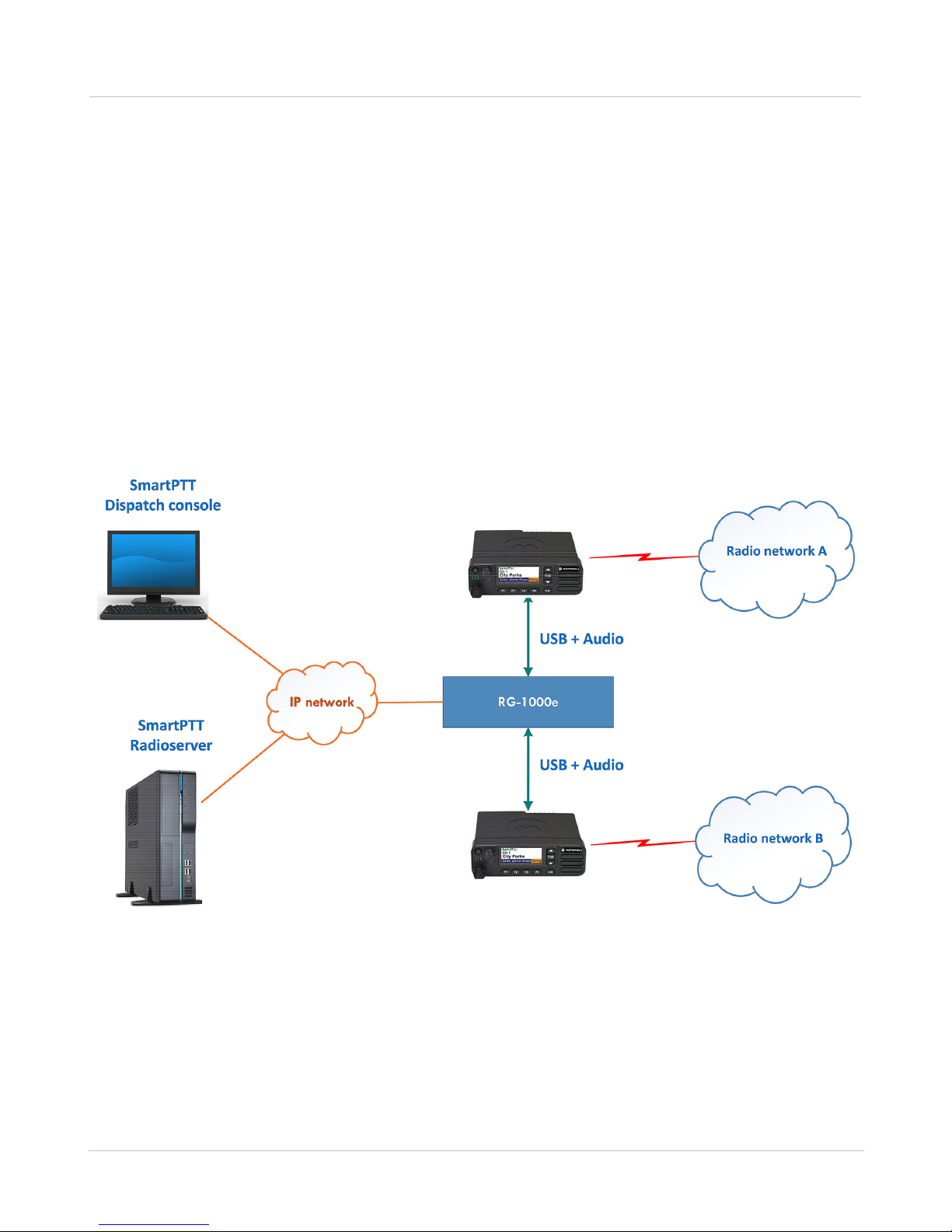
Fig. 1 MOTOTRBO control stations: remote connection to SmartPTT dispatch system
The RG-1000e GATEWAY is used in SmartPTT dispatch systems for remote control of MOTOTRBO control
station(s) or radios through the SmartPTT Radioserver (hereinafter referred to as radioserver) in the corporate IP
network or Internet. It is required to use MOTOTRBO Radios: EMEA region DM46**e, DM44**e, DM46**, DM44**,
DM2600 ; APAC region XiR M8600i, XiR M8600, XiR M6660 ; NA region XPR 5***e, XPR 5***, XPR 2500 ; LA
region DGM 8***e, DGM 5***e, DGM 8***, DGM 5***, DEM500.(*)
The RG-1000e GATEWAY provides the conversion of audio signals and radio control commands to IP packets
and the transmission of these packets over the network.The usage of the RG-1000e GATEWAY is an alternative
to direct connection of control stations to the radioserver via a USB interface.
The figure below shows an example of remote control using an RG-1000e GATEWAY.
6
* Note 1: low tier Mototrbo radios DM1400/DM1600, CM200d/CM300d, DEM300/DEM400, XIR M3188/XIR M3688
can not be used with RG-1000e. The 1st generation of Mototrbo radios can not be usedwith with RG-1000e.
Note 2: due to Mototrbo firmware limitation middle tier radios DM2600/XPR2500/DEM500/XiR6660 can not setup
outgoing All Call. Indicated middle tier radios may receive incoming All Call and play feedback. This limitation may
be eliminated using non-typical TG ID for All Call feature.
User GuideRG-1000e Remote Gateway

2 System structure
The system of remote management of the control station consists of the following components:
· RG-1000e GATEWAY,
· radio connected to the RG-1000e GATEWAY, and
· SmartPTT software based on Client–Server technology.
The RG-1000e GATEWAYs are connected to the SmartPTT server-based application, which manages the RG1000e GATEWAY, and interact with this application. For IP network connection, RG-1000e GATEWAY has the
10BASE-T/100BASE-TX Ethernet interface with auto detection of the cable type. For the interaction between the
system components, the RG-1000e GATEWAY and radioserver get a static IP address and the TCP and
UDP/RTP port numbers, which are used for the radio control commands and audio transmission from the dispatch
console. The RG-1000e GATEWAY can be used in the following cases:
· As a remote dispatcher's workplace outstation in digital networks without repeaters (Direct Mode
communication).
· In the conventional or trunking MOTOTRBO networks, where the direct IP connection to the repeaters is
unavailable.
7
· When the connection to the repeaters in MOTOTRBO networks is based on the hybrid scheme, where the data
interchange is performed via the NAI interface of the repeaters and the voice data transmission—via the pool of the
control stations.
This system offers the following advantages:
· It allows you to organize the dispatching system in the networks, where the direct connection of the dispatching
system to the MOTOTRBO repeaters via the IP network is unavailable.
· It allows you not to place radioserver close to the control stations within the radio network coverage area.
· It allows you to avoid interference and induced noise between neighboring control stations.
When planning the system, it is required to take into account the packet delivery delay in the IP network, which
causes the corresponding radio response delay to the control commands and voice data transmission.
User GuideRG-1000e Remote Gateway
2.1 Technical specification
Network interface parameters
Connector
RJ45
Standard
10BASE-T (IEEE 802.3) / 100BASE-TX (IEEE 802.3u)
Supported TCP/IP protocols
UDP, ICMP, IPv4, ARP
Auto tuning of auto switching
Transmission rate—10/100 Mbps
Operation mode—duplex/half-duplex
Auto detection of the cable type—Auto-MDI/MDI-X
Radio interface parameters
Number of ports for radio connections
Two ports, Port 1 and Port 2 may be used simultaneously, independently
from each other
Voice channel
768 kbps (48 kHz x 16 bits) PCM, duplex
Frequency band of voice channel
20–3600 Hz
IP voice channel coding
64 kbps (G711 A-Law/Mu-Law)
Transport protocol of control channel
UDP and TCP
Required bandwidth for control
channel
From 15 kbps
Transport protocol of voice channel
UDP and RTP
Required bandwidth for voice IP
channel
~128 kbps
Time delay\latency (SmartPTT
Radioserver <-> RG-1000e), ms
Up to 1250 ms one-way (2500 ms round-trip)
Support of radio operation modes
MOTOTRBO radio models
EMEA region DM46**e, DM44**e, DM46**, DM44**, DM2600; APAC
region XiR M8600i, XiR M8600, XiR M6660; NA region XPR 5***e,
XPR 5***, XPR 2500; LA region DGM8***e, DGM 5***e, DGM 8***, DGM
5***, DEM500
Radio operation modes
Digital MOTOTRBO
Analog MOTOTRBO
MOTOTRBO network topologies
Talkaround mode
Single repeater
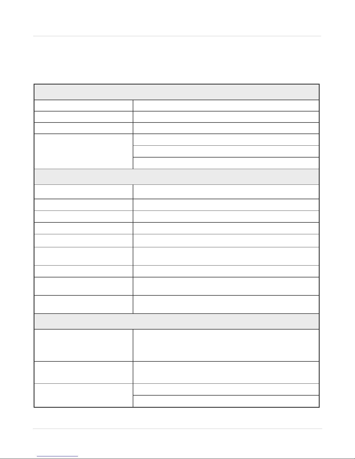
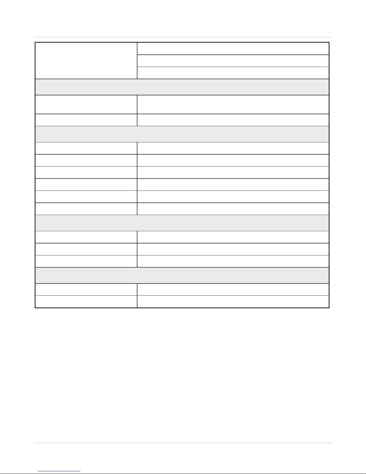
2.1 Technical specification
Technical parameters of the RG-1000e GATEWAY are listed in table 1 below.
Table 1 RG-1000e GATEWAY technical parameters
8
User GuideRG-1000e Remote Gateway
2.1 Technical specification
Multisite conventional network (IP Site Connect)
Single site trunking network (Capacity Plus)
Multisite trunking network (Linked Capacity Plus, Capacity MAX)
Power supply
Supply voltage
11–15.0 VDC, power can be applied via Power socket and\or radio
Radio1 socket and\or radio Radio2 socket
Power consumption
200 mA or less
Design
Dimensions
180x144x30 mm
Ethernet connector
RJ45 8P8C (8 pins)
Radio connector
3M 10126-*** jack (26 pins)
Power connector
Phoenix Con PTSM 0.5-3 (3 pins)
Audio connector
Phoenix Con PTSM 0.5-2 (2 pins)
Terminal connector
USB mini-B jack (4 pins)
Operating conditions
Operating temperature range
–4° to 140°F (–20° to +60°C)
Relative humidity
Up to 85% at 86°F (30°C)
Operating hours
24x7
Control terminal
Interface port
USB 1.0 (12 MBps), Device port
Software
RG-1000e Customer Programming Software (RG-1000e CPS)
· RG-1000e GATEWAY
—1 pcs.,
· interface cable*
—1 pcs.,
· FTP5E cable, 6.56 feet (2 m)
—1 pcs.,
· the following clamping elements of RG-1000e GATEWAY:
o bracket
—2 pcs.,
o M3x6 screw
—4 pcs.,
o M5x10 screw
—2 pcs.,
o 5x20 self-tapping screw
—4 pcs.,
9
2.2 Delivery set
The RG-1000e GATEWAY delivery set includes the following components:
User GuideRG-1000e Remote Gateway

2.2 Delivery set
· USB cable A-miniB, 1 m.
—1 pcs.
10
* The 1st interface cable is included in the RG-1000e GATEWAY delivery set by default (for Mototrbo DM
46**e/DM 44**e, XiR M86**i, DGM 8***e/DGM 5***e radios).
The 2nd interface cable you need to purchase additionally.
Interfaces cables for DM 2600, XiR M6660, XPR 2500, DEM 500 radios will be included in the delivery set by
special request.
User GuideRG-1000e Remote Gateway

11
3 Operating principles
The simplest system configuration includes the remote RG-1000e GATEWAY with one connected control station,
SmartPTT radioserver and the dispatch console.
The dispatch console does not interact directly with the RG-1000e GATEWAY. Instead, the dispatch console
transmits data and audio to the radioserver, which then transmits them to the RG-1000e GATEWAY.
The interaction between the dispatch console and the radioserver is not considered in this document, as it is
described in detail in the corresponding SmartPTT software documentation.
The operating principle of the RG-1000e GATEWAY is based on the following elements:
1. Receiving and transmitting radio control commands intended for the management of the control station.
2. Receiving and transmitting the audio signals.
3. Transforming the radio control commands and audio signals into the asynchronous flow of digital data.
4. Encoding of the asynchronous flow of digital data and its transmission to the radioserver via IP network.
To work through the IP network, the RG-1000e GATEWAY and radioserver must be given static IP addresses.
After the connection is made, the IP communication channel is established that provides the transmission of the
following data via the UDP protocol:
· radio control commands between the control station and the radioserver;
· audio signals from the radio receiver and from the microphone of the dispatch console.
The radioserver may host multiple RG-1000e GATEWAY gateways. Their number is limited only by the license
conditions or by the technical constraints of the communication channels.
To establish the IP communication channels between the RG-1000e GATEWAY and radioserver, the TCP protocol
and UDP/RTP protocols are used. The TCP protocol serves to transmit the radio control commands. The RTP
protocol is used to transmit audio, registration messages (ARS), short text messages (TMS), etc.
To separate the channels on the RG-1000e GATEWAY, each channel is assigned a corresponding IP address
and UDP/TCP port number from a range of 1024...65536. When the IP channels of the RG-1000e GATEWAY have
equal values of IP address and UDP port, the connection is performed in tandem on idle IP channels.
To process the signals of the radio audio path, compression is used in the RG-1000e GATEWAY. The built-in
compressor receives and transmits audio signals using 64 kbps Mu-Law PCM encoding.
Below you will find examples of network topologies and configurations when the RG-1000e GATEWAY and
radioserver are connected. The details about how to connect the radioserver to other equipment or to the dispatch
console are not shown in the examples.
The RG-1000e GATEWAY network interface meets the 10BASE-T (IEEE 802.3) / 100BASE-TX (IEEE 802.3u)
specifications and may be connected to external equipment that meets the same network interface specifications.
Below you will find examples of network topologies and configurations when the RG-1000e GATEWAY and
radioserver are connected. The details about how to connect the radioserver to other equipment or to the dispatch
console are not shown in the examples.
User GuideRG-1000e Remote Gateway
 Loading...