


Model CG60
Model CG60DL
Corrosion Gauge
Operating Instructions
en

en
This product meets the Electromagnetic Compatibility Directive.
The product is Class A, Group 1 ISM equipment according to CISPR 11.
Group 1 ISM product: A produ ct in which there is intentionally generated and/or used conductively coupled radiofrequency energy which is necess ary for the internal functioning of the equipment itself.
Class A product are suitab le for use in all establ ishments other than domesti c and those di rectly conn ected to a low voltage power supply network which supplies buildings used for domestic purposes.
is a registered trademark of Elcometer Limited.
All other trademarks acknowledged.
© Copyright Elcometer Limited. 2011.
All rights reserved. No part of this document may be reproduced, transmitted, transcribed, stored (in a retrieval
system or otherwise) or translated into any language, in any form or by any means (electronic, mechanical, magnetic,
optical, manual or otherwise) without the prior written permission of Elcometer Limited.
A copy of this Instruction Manual is available for download on our Website via www.elcometer.com.
Doc.No. TMA-0498 Issue 01
Text with Cover No: 23225

Contents
1 About your gauge . . . . . . . . . . . . . . . . . . . . . . . . . . . . . . . . . . . . . . . . . . . . . . . . . . . . . . . . . . . . . . . . . . . . . 2
2 The keypad . . . . . . . . . . . . . . . . . . . . . . . . . . . . . . . . . . . . . . . . . . . . . . . . . . . . . . . . . . . . . . . . . . . . . . . . . . . 4
3 Getting started . . . . . . . . . . . . . . . . . . . . . . . . . . . . . . . . . . . . . . . . . . . . . . . . . . . . . . . . . . . . . . . . . . . . . . . . 8
4 The display . . . . . . . . . . . . . . . . . . . . . . . . . . . . . . . . . . . . . . . . . . . . . . . . . . . . . . . . . . . . . . . . . . . . . . . . . . 10
5 Measurement modes. . . . . . . . . . . . . . . . . . . . . . . . . . . . . . . . . . . . . . . . . . . . . . . . . . . . . . . . . . . . . . . . . . 13
6 Setting up the gauge . . . . . . . . . . . . . . . . . . . . . . . . . . . . . . . . . . . . . . . . . . . . . . . . . . . . . . . . . . . . . . . . . . 15
7 Measurement - Taking readings. . . . . . . . . . . . . . . . . . . . . . . . . . . . . . . . . . . . . . . . . . . . . . . . . . . . . . . . . 21
8 Measurement options . . . . . . . . . . . . . . . . . . . . . . . . . . . . . . . . . . . . . . . . . . . . . . . . . . . . . . . . . . . . . . . . . 23
9 Measurement - Recording your readings (CG60DL only) . . . . . . . . . . . . . . . . . . . . . . . . . . . . . . . . . . . . 28
10 Transferring readings to a computer. . . . . . . . . . . . . . . . . . . . . . . . . . . . . . . . . . . . . . . . . . . . . . . . . . . . . 31
11 Storage . . . . . . . . . . . . . . . . . . . . . . . . . . . . . . . . . . . . . . . . . . . . . . . . . . . . . . . . . . . . . . . . . . . . . . . . . . . . . 33
12 Maintenance . . . . . . . . . . . . . . . . . . . . . . . . . . . . . . . . . . . . . . . . . . . . . . . . . . . . . . . . . . . . . . . . . . . . . . . . . 34
13 Technical specification . . . . . . . . . . . . . . . . . . . . . . . . . . . . . . . . . . . . . . . . . . . . . . . . . . . . . . . . . . . . . . . . 34
14 Warranty . . . . . . . . . . . . . . . . . . . . . . . . . . . . . . . . . . . . . . . . . . . . . . . . . . . . . . . . . . . . . . . . . . . . . . . . . . . . 36
15 Spares. . . . . . . . . . . . . . . . . . . . . . . . . . . . . . . . . . . . . . . . . . . . . . . . . . . . . . . . . . . . . . . . . . . . . . . . . . . . . . 38
16 Transducers . . . . . . . . . . . . . . . . . . . . . . . . . . . . . . . . . . . . . . . . . . . . . . . . . . . . . . . . . . . . . . . . . . . . . . . . . 38
17 Condition and preparation of surfaces . . . . . . . . . . . . . . . . . . . . . . . . . . . . . . . . . . . . . . . . . . . . . . . . . . . 43
18 Application notes. . . . . . . . . . . . . . . . . . . . . . . . . . . . . . . . . . . . . . . . . . . . . . . . . . . . . . . . . . . . . . . . . . . . . 43
19 Sound velocities of common materials. . . . . . . . . . . . . . . . . . . . . . . . . . . . . . . . . . . . . . . . . . . . . . . . . . . 46
en
1

en
hank you for purchasing this Model CG60/Model CG60DL Corrosion Gauge. Welcome to Elcometer NDT.
The Elcometer CG60 and CG60DL Co rrosion Gau ges are wo rld beatin g product s. With the purchas e of this
T
gauge you now have access to the worldwide service and support network of Elcometer NDT . For more
information visit our website at www.elcometerndt.com.
1 ABOUT YOUR GAUGE
The Model CG60 and CG60DL Corrosio n Gauges are handheld gauges for fast and accurate meas urement of
material thickness.
The Model CG60 and CG60DL are both capable of measuring the thickness of various materials with accuracy as
high as ± 0.1 mm (± 0.004"). The princi pal advan tage of ultr asonic measu rement over traditio nal methods i s that
ultrasonic measurements can be pe rformed with access to only one side of the material being measured.
The multi-mode feature of t he Model CG60 and CG60DL allows the user to toggle between pulse- echo mode
(standard measurements) and ec ho-echo mode (eliminate paint or co ating thickness).
The Model CG60DL model includes all the features of the Model CG60 model plus a data-logging (memory) facility
which allows readings to be stored in batches before being downloaded to a computer.
This manual describes the operation of the Model CG60 and the Model CG60DL.
1.1 STANDARDS
The Model CG60 and CG60DL Corrosion Gauges ca n be used in accordance with the following Standa rds and
test methods ASTM E 797, EN 14127 & EN 15317.
2

1.2 WHAT THIS BOX CONTAINS
A
Model CG60 Gauge or Model CG60DL Gauge, Bottle of couplant, Battery, 2 x, Carrying case, Test
certificate, Operating instructions, CD with data transfer and data collection software - CG60DL only, RS232
cable and USB to Serial converter CG60DL only
Note: The box does not include a transducer; these must be ordered separately. To order a transducer,
contact Elcometer or your local Elcometer NDT supplier.
en
Elcometer 208 DL
Ultrasonic Thickness Gauge
Data Logger
MODE
MEM
CAL
LRM
SCAN
DUAL
PRB
SEND
CLR
CAL
SEND
MULTI
PRB
0
ON
IN
IN
0
OFF
MM
MM
R
Elcometer 208
Ultrasonic Thickness Gauge
ALRM
CAL
MEM
MODE
SCAN
DUAL
PRB
SEND
CLR
SEND
CAL
MULTI
PRB
MM
0
IN
ON
OFF
0
R
Figure 1. Model CG60 and CG60DL Corrosion Gauges
3

en
2 THE KEYPAD
2.0.1 Model CG60 keypad
The ON/OFF key switches the gauge on or off.
To switch the gauge on, press the ON/OFF key. The gauge will perform a brief test by illuminating all of the
segments in the display. After one second, the display will show the internal software version number and
then the measurement mode ‘P-E’ or ‘E-E’. The display then shows ‘0.00’ (or ‘0.000’ if using imperial units),
indicating the gauge is ready to take readings.
To switch the gauge off press the ON/OFF key. The gauge retains all of its settings even when the power is
off. The gauge also features an ‘auto-power down’ function designed to conserve battery life. If the gauge is
idle for 5 minutes, it will switch itself off.
The PRB-0 key sets the gauge to zero in much the same way that a mechanical micrometer is set to zero.
PRB
If the gauge is not set to zero correctly, all of the measurements that the gauge makes may be in error by
0
some fixed value.
See “Setting up the gauge” on page 15.
When the Model CG60 is taking readings, press the CAL key to adjust calibration.
Calibration adjustment sets the sound-velocity value that the gauge uses when calculating thickness. The
gauge will either calculate the sound-velocity from a sample of the material bei ng measured, or allow a known
velocity value to be entered directly. See “Calibration” on page17.
The IN/MM key toggles between metric (mm) and imperial (inches) units.
IN
IN
This key may be used at any time, whether the gauge is displaying a thickness (MM or IN) or a velocity value
MM
MM
(M/s or IN/µs)
4

The UP arrow/SCAN key has two functions.
When the Model CG60 is in CAL or ALARM mode, press this key to increase numeric values on the display.
An auto-repeat function is built in, so that when the key is held down, numeric values increment at an
increasing rate.
When the Model CG60 is taking readings, this key switches SCAN measurement on and off.
See “Measurement options” on page 23.
The DOWN arrow/Backlight key has two functions.
When the Model CG60 is in the CAL or ALARM mode, press this key to decrease numeric values on the
display. An auto-repeat function is built in, so that when the key is held down, numeric values decrease at an
increasing rate.
When the Model CG60 is taking readings, the DOWN arrow key switches the display backli ght between thre e
settings; on, off and auto.
See “Backlight” on page 27.
The ALRM key has two functions.
Hold down the ALRM key when switching on the Model CG60 to switch the audible beeper on or off.
When the Model CG60 is taking readings, press the ALRM key to toggle the alarm on or off, and to allow the
nominal thickness value to be adjusted.
See “Alarm” on page 24.
The DUAL/MULTI key toggles between pulse-echo measurement mode and echo-echo measurement mode.
DUAL
This enables the user to switch very conveniently between measurement modes depending on application
MULTI
requirements.
See “Measurement options” on page 23.
The SEND key sends the currently displayed thickness measurement to an external storage device via the
RS232 port.
See “Transferring readings to a computer” on page 31.
en
5

en
2.0.2 Model CG60DL keypad
The ON/OFF key switches the gauge on or off.
To switch the gauge on press the ON/OFF key. The gauge will perform a brief test by illuminating all of the
segments in the display. After one second, the display will show the internal software version number, the
current batch location and location status, and then the measurement mode ‘P-E’ or ‘E-E’. The display then
shows ‘0.00’ (or ‘0.000’ if using imperial units), indicating the gauge is ready to take rea dings.
To switch the gauge off press the ON/OFF key. The gauge retains all of its settings even when the power is
off. The gauge also features an ‘auto-power down’ function designed to conserve battery life. If the gauge is
idle for 5 minutes, it will switch itself off.
The PRB-0 key sets the gauge to zero in much the same way that a mechanical micrometer is set to zero.
PRB
If the gauge is not set to zero correctly, all of the measurements that the gauge makes may be in error by
0
some fixed value.
See “Setting up the gauge” on page 15.
When the Model CG60DL is taking readings, press the CAL key to adjust calibration.
Calibration adjustment sets the sound-velocity value that the gauge uses when calculating thickness. The
gauge will either calculate the sound-velocity from a sample of the material bei ng measured, or allow a known
velocity value to be entered directly.
See “Calibration” on page 17.
When the Model CG60DL is taking readings, press the MODE key to adjust the features and settings of the
gauge (alarm, scan, units, P-E/E-E, backlight, and beeper). The MODE key is used in conjunction with the
MODE
arrow and SEND keys to enable/disable the features and settings.
6

The UP arrow key has three functions.
When the gauge is in CAL or ALARM mode, press this key to increase numeric values on the display. An
auto-repeat function is built in, so that when the key is held down, numeric values increment at an increasing
rate. When MODE key has been pressed, the UP arrow key scrolls through the various features and settings
of the gauge.
When the data-logging feature has been activated by pressing the MEM key, pressing the UP arrow key
scrolls through the various files, memory locations, and functions of the data logger.
The DOWN arrow key has three functions.
When the gauge is in the CAL or ALARM mode, press this key to decre ase numeric values on t he display. An
auto-repeat function is built in, so that when the key is held down, numeric values decrease at an increa sing
rate. When MODE key has been pressed, the DOWN arrow key scrolls through the various features and
settings of the gauge.
When the data-logging feature has been activated by pressing the MEM key, pressing the DOWN arro w key
scrolls through the various files, memory locations, and functions of the data logger.
The MEM key enables/disables the data logging feature of the Model CG60DL. This key is used in
conjunction with the UP/DOWN arrows, SEND, and CLR keys. These keys, in combination, control the data
MEM
logging features of the Model CG60DL.
See “Measurement options” on page 23.
The CLR key is used with the data-logging feature of the Model CG60DL. This key clears the contents of an
CLR
entire batch, or individual memory locations. The CLR key is also used to send an obstruct message (ObS t ) to
an individual memory location. The ObSt symbol would indicate that the user was unable to take a reading at
a particular location. See “Measurement options” on page23.
The SEND key is used for sending data to internal memory locations, and external peripheral devices (serial
printer or computer). The SEND key is also used to select data logging functions in the Model CG60DL.
en
7

en
A
3 GETTING STARTED
3.1 FITTING BATTERIES
The Model CG60/CG60DL may be used with dry cell batteries or rechargeable batteries.
2 x LR6 (AA) alkaline batteries are supplied in the kit.
When the battery voltage is low the entire display will start to flash. When
this occurs the batteries should be replaced.
To fit or replace batteries:
1. Locate battery compartment cover (Figure 2) at top of gauge.
2. Unscrew battery compartment cover.
3. Referring to battery polarity instructions on rear of gauge, insert batteries into gauge ensuring correct polarity.
4. Replace battery compartment cover.
Note: Remove the batteries from the gauge if it is to remain unused for a
long period of time. This will prevent damage to the gauge in the event of
malfunction of the batteries.
8
Battery
compartment
cover
Elcometer 208 DL
Ultrasonic Thickness Gauge
Data Logger
MODE
MEM
CAL
LRM
SCAN
DUAL
PRB
SEND
CLR
CAL
SEND
MULTI
PRB
0
ON
IN
IN
0
OFF
MM
MM
R
Figure 2. Fitting batteries

3.2 CHOOSING THE TRANSDUCER
When you purchased your gauge you should have also purchased a suitable transducer for your
application. If you have not yet done so, refer to “Transducers” on page 38, which will help you identify the
correct transducer type. Alternatively contact Elcometer NDT, your local Elcometer NDT supplier or visit
www.elcometerndt.com.
3.3 FITTING THE TRANSDUCER
The transducer (Figure 3) transmits and receives ultrasonic
sound waves that the gauge uses to calculate the thickness of
the material being measured.
The transducer connects to the gauge via the attached cable,
and two coaxial connectors. When using transducers
manufactured by Elcometer NDT, the orientation of the dual
coaxial connectors is not critical; either plug may be fitted to
either socket.
The transducer must be used correctly in order for the gauge to produce accurate, reliable measurements.
Figure 3. Typical Transducer
en
9

en
Figure 4 shows the two semicircles of the wearface and the
barrier separating them.
One of the semicircles transmits ultrasonic sound into the
material being measured, and the other semicircle receives
the sound echoes back into the transducer. When the
transducer is placed against the material being measured, it is
the area directly beneath the centre of the wearface that is
being measured.
3.4 SWITCHING ON/OFF
To switch on or off, press the on/off key The gauge will switch off automatically after 5 minutes of
inactivity.
Figure 4. Transducer - bottom view
4 THE DISPLAY
The display segments for the Model CG60 and the Model CG60DL are
shown in Figure 5.
The following section describes the individual parts of the display and
their meaning.
10
Wearface
INMM/ s
µ
Figure 5. The LCD Display -
Elcometer CG60 and

Display segment Information displayed
INMM/ s
µ
INMM/ s
µ
INMM/ s
µ
The numeric portion of the display consists of 4 complete digits preceded by a leading ‘1’,
and is used to display numeric values, as well as occasional simple words which indicate the
status of various settings. When the gauge is displaying thickness measurements, the
display will hold the last value measured, until a new measurement is made. Additionally,
when the battery voltage is low, the entire display will begin to flash. When this occurs, the
batteries should be replaced.
These eight vertical bars form the Stability Indicator. Only the left-most bar and the und erline
will be on when the gauge is idle. Six or seven of the bars should be on when the gauge is
taking a measurement. If fewer than five bars are on, the gaug e is having dif ficulty achie ving
a stable measurement, and the thickness value displayed could be in error.
Refer to “Read display” on page 22 and “Transducers” on page 38 for information on how to
achieve a stable measurement.
When the + symbol is on and blinking, this indicates that the Model CG60DL is currently
operating in echo-echo (through-paint/coating) mode.
en
11

en
Display segment Information displayed
IN / s
µ
MM
When the MM symbol is on, the gauge is displaying a thickness value in millimetres. The
maximum value displayed is 25.40 millimetres (MM).
12
INMM/ s
µ
INMM/ s
µ
IN / sMM
µ
When the IN symbol is on, the gauge is displaying a thickness value in inches. The
maximum thickness that can be displayed is 1.0000 inches (IN).
When the M symbol is on, in conjunction with the /s symbol, the gauge is displaying a soundvelocity value in metres-per-second (M/S).
When the IN symbol is on, in conjunction with the /µs symbol, the gauge is displaying a
sound-velocity value in inches-per-microsecond (IN/µS).

4.1 FRONT PANEL LIGHTS
Green light illuminates when:
• The alarm mode is active, and
• the measured thickness is greater than the alarm value.
Red light illuminates when:
• The alarm mode is active, and
• the measured thickness is less than the alarm value.
5 MEASUREMENT MODES
Your gauge has two measurement modes, Pulse-Echo and Echo-Echo.
5.1 PULSE-ECHO MODE (P-E)
This mode measures from the initial pulse (sometimes referred to as an artificial zero) to the first echo
(reflection). This mode only requires one reflection and it is therefore the most sensitive mode for measuring
weak reflections (flaws) typically found when measuring heavily corroded metals. If this mode is used to
measure a coated sample, then the thickness of the substrate plus coating will be measured.
Note: Rough surface conditions can have an effect on the overall accuracy in this mod e. If the surface
condition is in question, the pulse-echo mode should be used in conjunction with performing an off block
automatic zero as the temperature gradient changes.
13
en

en
5.2 ECHO-ECHO MODE (E-E)
This mode measures between two reflections. This technique is commonly used to eliminate errors from
surface coatings and also to make measurements in multiple layered materials. The disadvantage is that
two echoes are needed which requires a much stronger echo (reflection).
Note: Echo-echo mode cannot be used for flaw or pit detection. Therefore, inspectors may need to use this
mode in conjunction with the standard coating off (pulse-echo) flaw detection mode for some applications.
Chassis tubing inspectors and sanctioning bodies will typically use the echo-echo mode for tubing with
powder coatings, and pulse-echo mode for tubing without coating. This combination of using both modes is
ideal for very detailed inspections.
To select measurement mode:
Model CG60 Model CG60DL
1. Press ON/OFF key to switch on the gauge.
2. Press DUAL/MULTI key to toggle between the measurement modes. The gauge will display P-E or E-E, depending on which mode the gauge is in.
3. Repeat step 2 until correct mode is displayed.
Selection of measurement mode is now complete.
14
1. Press ON/OFF key to switch on the gauge.
2. Press MODE key to activate features and settings. The gauge will display GAtE P-E or GAtE E-E, depending on which mode the gauge is in.
3. Press SEND key to toggle between the measurement modes.
4. Press MODE key when correct mode is displayed.

6 SETTING UP THE GAUGE
6.1 TRANSDUCER - ZEROING
Setting the zero point of the gauge is important for the same reason that setting the zero on a mechanical
micrometer is important. If the zero point of the gauge is not set correctly, all of the measurements the gauge
makes will be in error by some fixed number. When the zero point of the gauge is set, this fixed error value
is measured and automatically corrected for in all subsequent measurements.
Though the gauge will remember the last zero point, it is generally a good idea to set the zero whenever the
gauge is switched on, as well as any time a different transducer is used. This will ensure that the zero point
of the instrument is always correct. The zero probe routine must be done prior to calibration.
To set the zero point:
1. Plug the transducer into the gauge ensuring that the connectors are fully engaged. Check that the wearface of the transducer is clean and free of any debris.
2. Press ON/OFF key to switch on the gauge.
3. The battery compartment cover on the top end of the gauge acts as a metal ‘probe-disc’. Apply a single droplet of ultrasonic couplant to the face of this disc.
15
en

en
4. Make sure that the gauge is in P-E (pulse-echo mode):
Model CG60 Model CG60DL
1. Press DUAL/MULTI key to toggle measurement mode to P-E.
Note: The Probe-Zero feature is not used in Echo-Echo through-paint mode, and has been disabled. If
the PRB-0 key is pressed, while in this mode, ‘nO’ followed by ‘Prb0’ will be displayed.
4. Press the transducer against the probe-disc, making sure that the transducer is flat against the surface (Figure 6). The display should show some thickness value, and nearly all the bars of the stability indicator should be illuminated.
5. While the transducer is firmly coupled to the probe-disc, press the PRB-0 key on the keypad. The gauge will display ‘Prb0’ while it is calculating the zero point.
6. Remove the transducer from the probe-disc.
Figure 6. Transducer pressed against probe-disc
When setting the zero point, the gauge will always use the sound-velocity value of the built-in probe-disc,
even if some other velocity value has been entered for making actual measurements.
16
1. Press MODE key.
2. Press SEND key to toggle measurement mode to P-E.
3. Press MODE key to confirm selection.
Elcometer 208

Though the gauge will remember the last zero point, it is generally a good idea to set the zero point
whenever the gauge is switched on, as well as any time a different transducer is used. This will ensure that
the zero point of the instrument is always correct.
6.2 CALIBRATION
In order for the gauge to make accurate measurements, it must be set to the correct sound-velocity for the
material being measured.
Different types of material have different sound-velocities. For example, the velocity of sound through steel
is 5918 m/s (about 0.233 in/µs) and the velocity of sound through aluminium is 6350 m/s (about 0.248
in /µs).
If the gauge is not set to the correct sound-velocity, all of the measurements the gauge makes will be
erroneous by some fixed percentage.
There are three methods of calibrating the Model CG60 and Model CG60DL gauges:
One-point
CALIBRATION: This is the simplest and most commonly used calibration procedure - optimising
linearity over large ranges. One-point calibration is carried out using a known thickness.
Two-point
CALIBRATION: This allows for greater accuracy over small ranges. Two-point calibration is carried
out using two known thicknesses.
Known velocity
CALIBRATION: The sound-velocity of the material being measured is entered directly into
the gauge.
Note: Although the gauge has a through-paint/coating feature, one-point and two-point calibrations must be
performed on material with the paint or coating removed. Failure to remove the paint or coating prior to
calibration will result in a multi-material velocity calculation that may be different from the actual material
velocity intended to be measured.
17
en

en
6.2.1 One-point calibration
This procedure requires a sample piece of the material to be measured, the exact thickness of which is
known, e.g. from having been measured by some other means.
1. Press ON/OFF key to switch on the gauge.
1. Set the zero point of the gauge - see “Setting up the gauge” on page 15.
2. Apply couplant to the sample piece.
3. Press the transducer against the sample piece, making sure that the transducer is flat against the
surface of the sample. The display should show some (probably incorrect) thickness value, and nearly
all the bars of the stability indicator should be illuminated.
4. Having achieved a stable reading, remove the transducer. If the displayed thickness changes from the value shown while the transducer was coupled, repeat
step 3 and 4.
5. Press the CAL key. The MM (or IN) symbol should begin flashing.
6. Use the UP and DOWN arrow keys to adjust the displayed thickness up or down, until it matches the known thickness of the sample piece.
7. Press the CAL key again. The M/s (or IN/µs) symbols should begin flashing. The gauge is now displaying the sound-velocity value it has calculated.
8. Press the CAL key once more to exit the calibration mode.
The gauge is now ready to perform measurements.
18

6.2.2 Two-point calibration
This procedure requires that the operator has two known thickness points on the test piece that are
representative of the range to be measured.
1. Set the zero point of the gauge - see “Setting up the gauge” on page 15.
2. Apply couplant to the sample piece.
3. Press the transducer against the sample piece, at the first calibration point, making sure that the
transducer is flat against the surface of the sample. The display should show some (probably
incorrect) thickness value, and nearly all the bars of the stability indicator should be illuminated.
4. Having achieved a stable reading, remove the transducer. If the displayed thickness changes from the value shown while the transducer was coupled, repeat
steps 3 and 4.
5. Press the CAL key. The IN (or MM) symbol should begin flashing.
6. Use the UP and DOWN arrow keys to adjust the displayed thickness up or down, until it matches the thickness of the sample piece.
7. Press the PRB-0 key. The display will flash 1OF2.
8. Repeat steps 3 to 6 on the second calibration point.
9. Press the CAL key again. The M/s (or IN/µs) symbols should begin flashing. The gauge is now displaying the sound-velocity value it has calculated.
10. Press the CAL key once more to exit the calibration mode.
The gauge is now ready to perform measurements within this range.
19
en

en
6.2.3 Known velocity calibration
This procedure requires that the operator knows the sound-velocity of the material to be measured. A table
of common materials and their sound-velocities can be found in “Sound velocities of common materials” on
page 46.
1. Press ON/OFF key to switch on the gauge.
2. Press the CAL key to enter calibration mode. If the MM (or IN) symbol is flashing, press the CAL key again, so that the M/s (or IN/µs) symbols are flashing.
3. Use the UP and DOWN arrow keys to adjust the displayed velocity up or down, until it matche s the sound-velocity of the material to be measured.
4. Press the CAL key once more to exit the calibration mode.
The gauge is now ready to perform measurements.
Note: At any time during the gauge calibration procedure (IN, MM, IN/µs, or M/s flashing in the display),
pressing the PRB-0 key will restore the gauge to the factory default sound-velocity for steel, 5918 m/s
(0.233 in/µs).
To achieve the most accurate measurements possible, it is generally advisable to calibrate the gauge to a
sample piece of known thickness. Material composition (and thus, its sound-velocity) sometimes varies from
lot to lot and from manufacturer to manufacturer. Calibration to a sample of known thickness will ensure that
the gauge is set as closely as possible to the sound-velocity of the material to be measured.
20

7 MEASUREMENT - TAKING READINGS
Disclaimer
Inherent in ultrasonic thickness measurement is the possibility that the instrument will use the second echo
rather than the first echo from the back surface of the material being measured while in standard pulse-echo
mode. This may result in a thickness reading which is TWICE what it should be.
In addition, measurements through very thick paint or coatings while using echo-echo mode may result in
the paint or coating being measured rather than the material intended. The responsibility for proper use of
the instrument and recognition of these types of phenomenon rests solely with the user of the instrument.
7.1 Before you start
• Set the zero point of the gauge.
See “Setting up the gauge” on page 15.
• Calibrate the gauge.
See “Calibration” on page 17.
• Select the correct measurement mode.
See “Measurement options” on page 23.
• Prepare the surface.
See “Condition and preparation of surfaces” on page 43.
21
en

en
7.2 PROCEDURE
7.2.1 Apply couplant
For the gauge to work correctly there must be no air gap between the transducer and the surface of the
material to be measured. This is achieved using a couplant.
Before the transducer is placed on the surface, put a small amount of couplant supplied with the gauge on
the surface of the material. Typically a single drop is sufficient.
7.2.2 Place transducer onto surface of material to be measured
Press the transducer wearface into the couplant. Moderate pressure on the top of the transducer using the
thumb or index finger is sufficient; it is only necessary to keep the transducer stationary and the wearface
seated flat against the surface of the material.
7.2.3 Read display
If six or seven bars of the stability indicator are showing, the display will be reading the correct thickness of
the material directly beneath the transducer.
If the stability indicator has fewer than five bars showing, or the numbers on the display seem erratic, check
to make sure that there is an adequate film of couplant beneath the transducer, and that the transducer is
seated flat against the material. If the condition persists, it may be necessary to select a different transducer
(size or frequency) for the material being measured.
The gauge will perform four measurements every second when the transducer is in contact with the surface
of the material. The display is updated as each reading is taken.
22

7.2.4 Remove transducer from surface
The display will show the last measurement made.
Note: Occasionally, a small film of couplant will be drawn out between the transducer and the surface as
the transducer is removed. When this happens, the gauge may perform a measurement through this
couplant film, resulting in a measurement that is larger or smaller than it should be. This phenomenon is
obvious when one thickness value is observed while the transducer is in place, and another value is
observed after the transducer is removed. If this happens, take the reading again using less couplant.
8 MEASUREMENT OPTIONS
8.1 SCAN MODE
Although the gauge excels at making single point measurements, it is sometimes desirable to examine a
larger region, searching for the thinnest point. The Model CG60 and CG60DL include a feature, called Scan
Mode, which allows it to do just that.
In normal operation, the gauge performs and displays four measurements every second, which is quite
adequate for single measurements. In Scan Mode, however, the gauge performs eight measurements
every second, but does not display them. While the transducer is in contact with the material being
measured, the gauge memorises the lowest measurement it finds. The transducer may be ‘scrubbed’
across a surface, and any brief interruptions in the signal will be ignored. When the transducer loses contact
with the surface for more than a second the gauge will display the lowest value it found.
Note: The Scan mode is not available in echo-echo mode, and has been disabled. If scan mode is selected
while in echo-echo mode, ‘nO’ followed by ‘SCAn’ will be displayed.
23
en

en
8.1.1 To switch scan mode on/off
Elcometer CG60 Elcometer CG60DL
1. Press ON/OFF key to switch on the gauge.
2. Press UP/SCAN key to toggle the status of the Scan mode. The gauge will display SCAn OFF or SCAn On depending on which mode the gauge is in.
3. Repeat step 2 to switch scan mode on or off.
Selection of scan mode is now complete.
8.2 ALARM
The Alarm feature of the Model CG60 and CG60DL allows the user to set an audible and visual alarm when
taking measurements.
If the alarm is switched on, the green light on the front panel of the gauge is illuminated. If the measurement
falls below the value set by the user, a red light shows on the front panel of the gauge and the beeper is
sounded if it is switched on.
Use of the red light and beeper improves the speed and efficiency of the inspection process by eliminating
constant viewing of the reading displayed.
24
1. Press ON/OFF key to switch on the gauge.
2. Press MODE key to activate features and settings.
3. Press UP and DOWN arrow keys to scroll to
SCAn symbol. The gauge will display SCAn
OFF or SCAn On depending on which mode
the gauge is in.
4. Press SEND key to switch scan mode on or off.
5. Press MODE key when finished.

8.2.1 To switch beeper on/off
Elcometer CG60 Elcometer CG60DL
en
1. While the gauge is off, press and hold down ALRM key.
2. Press ON/OFF key to switch on the gauge.
3. Release ALRM key. The gauge will display bEEP OFF or bEEP On depending on whether the beeper is on or off.
4. Repeat steps 1 to 3 to toggle between bEEP ON and bEEP OFF.
Selection of beeper on/off is now complete.
1. Press ON/OFF key to switch on the gauge.
2. Press MODE key to activate features and settings.
3. Press UP or DOWN arrow keys to scroll to
bEEP. The gauge will display bEEP OFF or
bEEP On depending o n whether the beeper is
on or off.
4. Press SEND key to toggle the status of the beeper on/off.
5. Press MODE key when finished.
25

en
8.2.2 To set alarm value and switch alarm on
Elcometer CG60 Elcometer CG60DL
1. Press ON/OFF key to switch on the gauge.
2. Press ALRM key to toggle the status of the alarm until the gauge displays:
ALAr followed by a thickness value and
flashing MM (or IN) symbol.
3. Press UP and DOWN arrow keys to adjust thickness value.
4. Press ALRM key when correct value is displayed.
The alarm value is now set and the alarm is switched on.
8.2.3 To switch alarm off
Repeat the steps in 8.2.2, but select ALAr OFF.
26
1. Press ON/OFF key to switch on the gauge.
2. Press MODE key to activate features and
3. Press UP or DOWN arrow keys to scroll to
4. Press SEND key. The gauge will display:
5. Press UP and DOWN arrow keys to adjust
6. Press SEND key when correct value is
7. Press MODE key.
settings.
ALAr. The gauge will display:
ALAr OFF
A thickness value and flashing MM (or IN)
symbol.
thickness value.
displayed.

8.3 BACKLIGHT
The gauge display includes a backlight. The backlight can be set to one of three modes - on/off/auto.
• ON - backlight is on
• OFF - backlight is off
• AUTO - backlight automatically illuminates while the gauge is making a measurement and switches off
after several seconds (to conserve battery life).
8.3.1 To set backlight mode
Model CG60 Model CG60DL
en
1. Press ON/OFF key to switch on the gauge.
2. Press DOWN key to toggle the status of the backlight. The gauge will display OFF, On or AutO, depending on backlight setting.
3. Repeat step 2 until the correct setting is displayed.
Selection of backlight mode is now complete.
1. Press ON/OFF key to switch on the gauge.
2. Press MODE key to activate features and settings.
3. Press UP and DOWN arrow keys to scroll to the LItE symbol. The gauge will display LItE OFF, LItE On or LItE AutO, depending on backlight setting.
4. Press SEND key until the correct setting is displayed.
5. Press MODE key.
27

en
9 MEASUREMENT - RECORDING YOUR READINGS (CG60DL ONLY)
The Model CG60DL is equipped with a data logging feature. This is a valuable reporting gauge for
inspection purposes. It increases efficiency by reducing the time it takes to manually record the
measurements during the inspection process. The gauge can then be connected to a computer or se rial
printer to save and print the results of the inspection.
The gauge has a memory capacity of 1000 readings. Measurements are stored in up to 10 batches (files),
each consisting of up to 100 readings (memory locations).
9.1 SETTING-UP THE DATA LOGGER
1. Press ON/OFF key to switch on the gauge.
2. Press MEM key to activate the data logger. The display will flash FILE F-01 (or the last batch used). There are 10 batches, numbered F-01 to F-
10.
3. Press the SEND key to enter batch setup. The current batch will be displayed (F-01, F-03, etc.)
4. Press the UP / DOWN arrow keys to scroll to the batch (1-10) that will be used.
5. Press the SEND key once again to select the batch. The display will flash FILE F-04 (or the selected batch).
6. Press the MEM key, to access the memory locations in the batch selected. The display will flash the current memory location (L007, L039, etc.), followed by the status of the
memory location. The memory location can contain one of three possible things:
• a measurement that was previously stored
28

• CLr in the display, indicating that the memory location is empty
• ObSt (obstruct) in the display, indicating that a measurement could not be obtained
7. Press the UP / DOWN arrow keys to advance to the desired memory location.
9.2 STORING A MEASUREMENT
1. Take a measurement and press the SEND key to store a reading in the memory location. The data logger will then automatically advance to the next memory location in sequential order.
2. Repeat step 1 as required.
9.3 DELETING CONTENTS OF A MEMORY LOCATION
The user may require a memory location that is currently full to be over written. The procedure for deleting
(clearing) the contents of the memory location is outlined in the following steps:
Note: This procedure assumes the steps in 9.1 and 9.2 have been completed, and 9.2 is being repeated.
1. Press the UP / DOWN arrow keys to move to the memory location to be cleared. If the memory location is currently full, the display will flash the FuLL symbol.
2. Press the CLR key to delete the contents of the memory location. The display will flash the memory location (L011, L099, etc.) and the CLr symbol.
3. Take another measurement, and press the SEND key to write to the same memory location just cleared.
29
en

en
9.4 DELETING CONTENTS OF AN ENTIRE BATCH
The user may require the contents of an entire batch to be cleared of all measurements. This would allow
the user to start a new list of measurements starting at memory location L001, for example. The procedure
is outlined in the following steps:
1. Press ON/OFF key to switch on the gauge.
2. Press MEM key to activate the data logging functions and settings.
3. Press SEND key to enter batch setup.
4. Press UP / DOWN arrow keys to scroll to the batch that is to be cleared of all measurements.
5. Press SEND key once again to select the batch. The display will flash FILE F-05 (or the batch selected).
6. Press UP / DOWN arrow keys to scroll to the flashing CLr F-05 (or the batch selected).
7. Press SEND key to select the clear batch option. The display will show CLr?
8. Press CLR key to confirm and clear the contents of the entire batch.
9. Press MEM key at any time to exit data logging functions.
9.5 DELETING CONTENTS OF ALL BATCHES
1. Press ON/OFF key to switch on the gauge.
2. Immediately press the CLR key. The display will show CLr?
3. Press CLR key once again to clear all batches.
30
10 TRANSFERRING READINGS TO A COMPUTER
Readings can be transferred from the Model CG60 and Model CG60DL to a computer. The Model CG60
will transfer readings as they are taken. The Model CG60DL will transfer readings as they are taken and
also transfer the contents of its memory.
A data transfer cable is used to connect the gauge to the computer. This cable is supplied with the Model
CG60DL and is available as an optional accessory for the Model CG60 (see “Spares” on page 38).
Elcometer recommends the use of NDT Link available from www.elcometerndt.com but other types of
software may also be used.
10.1 CONNECTING THE DATA TRANSFER CABLE
1. Plug the 9-pin female D-type connector on one end of the data transfer cable into the COM port on the PC, or USB to COM adapter.
2. Plug the jack connector on the other end of the data transfer cable into the RS232 data connection socket on the bottom of the gauge (Figure 7).
3. Start the communications software.
4. Select gauge type Elcometer CG60 or CG60DL.
PRB
IN
IN
0
MM
MM
Figure 7. RS232 data connection socket
ON
OFF
R
RS232 data connection socket
31
en

en
10.1.1 Transferring data
Model CG60
After taking a measurement, press the SEND key to send the measurement to the computer.
Model CG60DL
Follow the instructions in “Measurement options” on page 23
10.1.2 Transferring one batch
1. Connect the gauge to a computer and start the data transfer software - see “Transferring readings to a computer” on page 31.
2. Press ON/OFF key to switch on the gauge.
3. Press MEM key to activate the data logging functions and settings.
4. Press SEND key to enter batch setup.
5. Press UP / DOWN arrow keys to scroll to the batch that is to be sent to the computer.
6. Press SEND key once again to select the batch. The display will flash FILE F-05 (or the batch selected).
7. Press UP / DOWN arrow keys to scroll to LISt F-05 (or the batch selected) flashing on the display.
8. Press the SEND key to send readings to the computer. The display will show buSY during data transfer. Wait until all the data has been transferred.
9. Press the MEM key to exit the data logging functions.
32

10.1.3 Transferring all batches
1. Connect the gauge to a computer and start the data transfer software.
2. Press ON/OFF key to switch on the gauge.
3. Press MEM key to activate the data logging functions and settings.
4. Press UP / DOWN arrow keys to scroll to SEnd ALL flashing on the display.
5. Press the SEND key to send readings to the computer. The display will show buSY during data transfer. Wait until all the data has been transferred.
6. Press the MEM key to exit the data logging functions.
11 STORAGE
The Model CG60/CG60DL gauge has a Liquid Crystal Display. If the display is heated above
50°C (120°F) it may be damaged. This can happen if the gauge is left in a car parked in strong
sunlight.
Always store the gauge in its case when it is not being used.
If the gauge is to remain unused for long periods of time, remove the batteries and store them separately.
This will prevent damage to the gauge in the event of malfunction of the batteries.
33
en

en
12 MAINTENANCE
The Model CG60/CG60DL is designed to give many years reliable service under normal oper ating and
storage conditions.
12.1 Transducer
The transducer will wear with repeated use. Transducer life depends on the number of measurements taken
and the manner in which readings are taken. To extend transducer life, always set the transducer down so
that it is perpendicular to the panel surface. Dragging the transducer along the surface will reduce the life
of the transducer. Replacement transducers are available from your local Elcometer NDT supplier or directly
from Elcometer.
12.2 Faults
The gauge does not contain any user-serviceable components. In the unlikely event of a fault, the gauge
should be returned to your local Elcometer NDT supplier or directly to Elcometer. The warranty will be
invalidated if the instrument has been opened.
13 TECHNICAL SPECIFICATION
13.1 Performance
Range (pulse-echo): 0.63 mm to 500 mm (0.025" to 19.999")
Range (echo-echo): 2.54 mm to 25.4 mm (0.1" to 1.0")
Resolution: 0.01 mm (0.001")
Accuracy: ±0.1 mm (±0.004"), depends on material and conditions
34

Sound-velocity range: 1250 m/s to 10 000 m/s (0.0492 in/μs to 0.3937 in/μs)
Physical Weight: 295 g (10 oz) including batteries
Size: 63.5 mm x 120.6 mm x 31.5 mm (2.5" x 4.5" x 1.24")
Operating temperature: -30°C to 50°C (-20°F to 120°F) (depending upon climatic conditions)
Case: Extruded aluminium body, Nickel plated aluminium end caps
13.2 Keypad
Type: Sealed membrane
Properties: Resistant to water and petroleum products
13.3 Power supply
Type: Internal batteries
Battery type: 2 x LR6 (AA), alkaline
Battery life: 200
a. Alkaline batteries must be disposed of carefully to avoid environmental contamination. Please consult your local
environmental authority for information on disposal i n your region.
Do not dispose of any batteries in fire.
b. Rechargeable batteries can be used if they are charged outside the gauge.
c. Battery life is reduced to approximately 120 hours when using rechargeable batteries. Follow the instructions
provided by the battery manufacturer when charging and disposing of rechargeable batte ries.
c
hours continuous (alkaline dry batteries)
a
dry batteries or rechargeableb equivalents
35
en

en
14 WARRANTY
Elcometer NDT warrants the Model CG60 and Model CG60DL ultrasonic gauges against defects in
materials and workmanship for a period of two years from receipt by the end user.
Additionally, Elcometer NCT warrants transducers and accessories against such defects for a period of 90
days from receipt by the end user. If Elcometer NDT receives notice of such defects during the warranty
period, Elcometer NDT will either, at its option, repair or replace products that prove to be defective. The
warranty will be invalidated if the instrument has been opened.
Should Elcometer NDT be unable to repair or replace the product within a reasonable amount of time, the
customer's alternative exclusive remedy shall be refund of the purchase price upon return of the product.
14.1 Exclusions
The above warranty shall not apply to defects resulting from: improper or inadequate maintenance by the
customer; unauthorised modification or misuse; or operation outside the environment al specifications for
the product.
Elcometer NDT makes no other warranty, either express or implied, with respect to this product. Elcometer
NDT specifically disclaims any implied warranties of merchantability or fitness for a particular purpose.
Some states or provinces do not allow limitations on the duration of an implied warranty, so the above
limitation or exclusion may not apply to you. However, any implied warranty of merchantability or fitness is
limited to the two-year duration of this written warranty.
This warranty gives you specific legal rights, and you may also have other rights, which may vary from
country to country, state to state or province to province.
36

14.2 Obtaining service during warranty period
If your hardware should fail during the warranty period, contact Elcometer NDT and arrange for servicing of
the product. Retain proof of purchase in order to obtain warranty service.
For products that require servicing, Elcometer NDT may use one of the following methods:
• Repair the product
• Replace the product with a re-manufactured unit
• Replace the product with a product of equal or greater performance
• Refund the purchase price.
14.3 After the warranty period
If your hardware should fail after the warranty period, contact Elcometer NDT for details of the services
available, and to arrange for non-warranty service.
37
en

en
15 SPARES
The Model CG60/CG60DL gauge is complete with all the items required to get started and take
measurements (transducers must be ordered separately). Over the life of the gauge replacement items may
be required. The following replacement and optional items are available from your local Elcometer NDT
supplier or directly from Elcometer.
Description Sales Part No.
2.25 MHz 1/4” Potted Side Transducer TX2M25CP-2
5 MHz 1/4” Potted Side Transducer TX5M00CP-4
5 MHz 1/4” Potted Side High Damped Transducer TX5M00CP-10
7 MHz 1/4” Potted Side High Damped Transducer TX7M50CP-6
10 MHz 1/4” Potted Side Transducer TX10M0CP-4
Ultrasonic Couplant, 120 ml (4 oz) TC-24034-1
Ultrasonic Couplant, 360 ml (12 oz) TC-24034-2
Ultrasonic Couplant, High Temperature 340°C (650°F), 60 ml (2 oz) TC-24034-4
Ultrasonic Couplant, High Temperature 480°C (896°F), 60 ml (2 oz) TC-24034-5
A wide range of other transducers are available - see “Transducers” on page 38 for further details.
16 TRANSDUCERS
The Model CG60 and Model CG60DL are capable of performing measurements on a wide range of
materials, from various metals to glass and plastics. Different types of material, however, have different
properties. The following paragraphs highlight the important properties of transducers which should be
considered when assessing a particular measurement task.
38

The best measurement condition is one where sufficient ultrasonic energy is sent into the material being
measured such that a strong, stable echo is received by the gauge.
Several factors affect the strength of ultrasound as it travels. These are outlined below:
16.1 INITIAL SIGNAL STRENGTH
The stronger a signal is to begin with, the stronger its return echo will be. Initial signal strength is largely a
factor of the size of the ultrasound emitter in the transducer. A large emitting area will send more energy
into the material being measured than a small emitting area. Therefore a 6 mm (1/4”) transducer will emit a
stronger signal than a 3 mm (1/8”) transducer.
16.2 ABSORPTION AND SCATTERING
As ultrasound travels through any material, it is partly absorbed. If the materials through which the sound
travels have any grain structure, the sound waves will experience scattering. Both of these effects reduce
the strength of the waves.
Higher frequency ultrasound is absorbed and scattered more than ultrasound of a lower frequency. It may
seem therefore that using a lower frequency transducer might be better in every instance, however low
frequencies are less directional than high frequencies.
16.3 GEOMETRY OF THE TRANSDUCER
The physical constraints of the measuring environment sometimes determine the suitability of a transducer
for a given job. The transducer may simply be too large to be used in confined areas. Also, the surface area
available for contacting with the transducer may be limited. Measuring on a curved surface may require the
use of a transducer with a matching curved wearface.
39
en

en
16.4 TEMPERATURE OF THE MATERIAL
When it is necessary to measure on surfaces that are exceedingly hot, special high-temperature
transducers may be necessary. Additionally, care must be taken when performing a ‘Calibration to Known
Thickness’ with a high temperature application - see “Measuring hot surfaces” on page 44.
16.5 SELECTING THE CORRECT TRANSDUCER
Elcometer NDT have a complete range of transducers to meet your requirements, including:
• A range of frequencies and sizes
• Straight and right angle
• Transducers available as potted or microdot transducers:
Potted transducers - transducer cable is permanently fixed to the transducer head.
Microdot transducers - transducer cable is fixed to the transducer head by a connector - allows
transducer heads to be replaced quickly and easily.
• High temperature transducers - temperature up to 480ºC (896ºF)
When selecting a transducer, it is important to choose one which will best meet your application, taking into
consideration:
• The measurement range
• The type of material to be tested
• The design of the transducer probe type
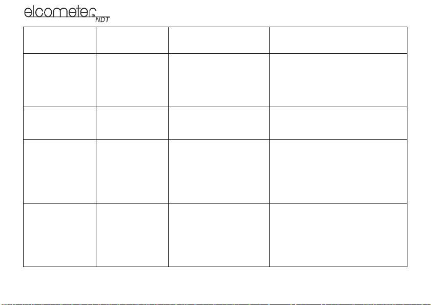
The following table gives guidance on the type of transducer required for a range of measurement tasks:
40

en
Material being
measured
High penetration
plastics and
castings
Corrosion and pit
detection in steel
and cast materials
Material thickness
measured through
a coating
Mode
PULSE-ECHO
(P-E)
PULSE-ECHO
(P-E)
ECHO-ECHO
(E-E)
Transducer type
required
Cast iron - 1MHz to 5MHz
transducer.
Cast aluminium - 10MHz
transducer.
Plastics typically require
lower frequency
transducers depending on
the thickness and makeup of the material.
Typically a 5MHz
transducer or higher is
required.
Special high damped
transducers are required;
typically the 3.5MHz,
5MHz, and 7.5MHz hi
damped transducers.
Notes
Larger diameters offer greater
penetration power because of the
crystal size, for difficult to measure
materials.
Use lower frequencies for greater
penetration and use higher
frequencies for better resolution.
These transducers are suitable for
use in both pulse-echo and echoecho modes. This enables you to
measure overall material thickness
using the Echo-echo mode, and then
switch to pit detection mode (Pulseecho) without changing transducers.
41
en
Material being
measured
Thin materials PULSE-ECHO
High temperature PULSE-ECHO
Noisy material Select a higher frequency
Measuring
extreme
curvatures or
areas of restricted
access
42
Mode
(P-E)
and
ECHO-ECHO
Transducer type
required
High frequency
transducers are required;
typically the 7.5MHz and
10MHz models with extra
resolution.
Special 2.25MHz and 5
MHz High temperature
transducers are required.
transducer to reduce this
noise - 7.5MHz and higher
for better resolution.
Higher frequency
transducers with smaller
diameters are required.
The smallest diameter
uses 3/16" crystals with a
contact area of .250"
Notes
The higher frequencies provide
greater resolution and a lower
minimum thickness rating overall.
Echo-echo mode will eliminate error
caused by temperature variations in
the delay line of the transducer.
Materials such as titanium, stainless
steel, and aluminium may produce
surface noise. This is a signal that
appears at the surface of the
material when using a dual element
delay line probe.

17 CONDITION AND PREPARATION OF SURFACES
The shape and roughness of the test surface are of paramount importance when carrying out ultrasonic
thickness testing. Rough, uneven surfaces may limit the penetration of ultrasound through the material, and
result in unstable, and therefore unreliable, measurements.
The surface being measured should be clean, and free of any small particles, rust, or scale. The presence
of such obstructions will prevent the transducer from seating properly against the surface. Often, a wire
brush or scraper will be helpful in cleaning surfaces. In more extreme cases, rotary sanders or grinding
wheels may be used, though care must be taken to prevent surface gouging, which will inhibit proper
transducer coupling.
Extremely rough surfaces, such as the pebble-like finish of some cast iron, will prove most difficult to
measure. These kinds of surfaces act on the sound beam like frosted glass acts on light, the beam becomes
diffused and scattered in all directions.
In addition to posing obstacles to measurement, rough surfaces contribute to excessive wear of the
transducer, particularly in situations where the transducer is ‘scrubbed’ along the surface.
18 APPLICATION NOTES
18.1 MEASURING TUBING
When measuring a piece of pipe to determine the thickness of the pipe wall, orientation of the transducers
is important.
43
en

en
If the diameter of the pipe is larger than approximately 100 mm (4”), measurements should be made with
the transducer oriented so that the gap in the wearface is perpendicular (at right angles) to the long axis of
the pipe.
If the diameter of the pipe is small, two measurements should be performed, one with the wearface gap
perpendicular to the long axis of the pipe, another with the gap parallel to the long axis of the pipe (Figure
8). The smaller of the two displayed values should then be taken as the thickness at that point.
Perpendicular Parallel
Figure 8. Transducer positioning on small diameter pipe
18.2 MEASURING HOT SURFACES
The velocity of sound through a material depends upon the temperature of the material. As materials heat
up, the velocity of sound in the material decreases. In most applications with surface temperatures less than
approximately 100°C (~200°F), no special procedures are required. At temperatures above 100°C
(~200°F), the change in sound-velocity of the material being measured starts to have a noticeable effect
upon the accuracy of ultrasonic measurement.
At such elevated temperatures, it is recommended that the user perform a calibration procedure (see
“Calibration” on page 17) on a sample piece of known thickness, which is at, or near, the temperature of the
material to be measured. This will allow the gauge to correctly calculate the velocity of sound through the
hot material.
44

When performing measurements on hot surfaces, it may also be necessary to use a high-temperature
transducer. It is recommended that the transducer be left in contact with the surface for as short a time as
needed to acquire a stable measurement. While the transducer is in contact with a hot surface, it will begin
to heat up, and through thermal expansion and other effects, may adversely affect the accuracy of
measurements.
18.3 MEASURING LAMINATED MATERIALS
The density (and therefore sound-velocity) of laminated materials may vary considerably from one piece to
another. Some laminated materials may even exhibit noticeable changes in sound-velocity across a single
surface. The only way to reliably measure such materials is by performing a calibration procedure on a
sample piece of known thickness. Ideally, this sample material should be a part of the same piece being
measured, or at least from the same lamination batch. By calibrating to each test piece individually, the
effects of variation of sound-velocity will be minimised.
An additional consideration when measuring laminates, is that any air gaps or pockets within the laminate
will reflect the ultrasound beam. This will be noticed as a sudden decrease in thickness in an otherwise
regular surface. While this may impede accurate measurement of total material thickness, it does provide
positive indication of air gaps in the laminate.
18.4 MEASURING THROUGH PAINT AND COATINGS
When measuring through paints and coatings the sound-velocity of the paint/coating may be significantly
different from the sound-velocity of the actual material being measured. An example of this would be a mild
steel pipe with approximately 0.6 mm (.025") of coating on the surface. The sound-velocity of the pipe is
5918 m/s (.2330 in/µsec), and the sound-velocity of the paint is 2286 m/s (.0900 in/µsec). If the gauge is
45
en

en
calibrated for mild steel pipe and measures through both materials, the actual coating thickness will appear
to be 2.5 times thicker than it actually is, as a result of the differences in sound-velocity.
The error can be eliminated by using the echo-echo mode to perform measurements for applications such
as these. In echo-echo mode, the paint/coating thickness will be eliminated entirely and the steel will be the
only material measured.
19 SOUND VELOCITIES OF COMMON MATERIALS
Material
Aluminium 6350 0.250 Paraffin 2210 0.087
Bismuth 2184 0.086 Platinum 3962 0.156
Brass 4394 0.173 Plexiglas 2692 0.106
Cadmium 2769 0.109 Polystyrene 2337 0.092
Cast Iron 4572 0.180 (Approx.) Porcelain 5842 0.230 (Approx.)
Constantan 5232 0.206 PVC 2388 0.094
Copper 4674 0.184 Quartz Glass 5639 0.222
Epoxy Resin 2540 0.100 (Approx.) Rubber, Vulcanised 2311 0.091
German Silver 4750 0.187 Silver 3607 0.142
Glass, Crown 5664 0.223 Steel 5918 0.233
Glass, Flint 4267 0.168 Steel, St ainless 5664 0.223
Gold 3251 0.128 Stellite 6985 0.275 (Approx.)
Ice 3988 0.157 Teflon 1422 0.056
Sound
velocity (m/s)
Sound
velocity (in/µs)
Material
Sound
velocity (m/s)
Sound
velocity (in/µs)
46

Material
Iron 5893 0.232 Tin 3327 0.131
Lead 2159 0.085 Titanium 6096 0.240
Magnesium 5791 0.228 Tungsten 5334 0.210
Mercury 1448 0.057 Water 1473 0.058
Nickel 5639 0.222 Zinc 4216 0.166
Nylon 2591 0.102 (Approx.)
Sound
velocity (m/s)
Sound
velocity (in/µs)
Material
Sound
velocity (m/s)
Sound
velocity (in/µs)
en
47
 Loading...