


Models CG70ABDL
& CG70BDL
en
Corrosion Gauge
Operating Instructions
0

en
This product meets the Electromagnetic Compatibility Directive.
The product is Class A, Group 1 ISM equipment according to CISPR 11
Group 1 ISM product: A product in which there is intentionally generated and/or used conductively
coupled radio-frequency energy which is necessary for the internal functioning of the equipme nt
itself.
Class A product are suitable for use in all establishments other than domestic and those directly
connected to a low voltage power supply network which supplies buildings used for domestic
purposes.
Note: In the close presence of some radio transmitters, erroneous readings may be given. If this
occurs tests should be repeated at another location.
These operating instructions are available for download on our website www.elcometerndt.com.
The following trademarks are registered trademarks of Elcometer Limited, Edge Lane, Manchester,
M43 6BU. United Kingdom:
Material Safety Data Sheets for the ultrasonic couplant supplied with the CG70ABDL & CG70BL
and available as an accessory, are available to download via our website:
Elcometer NDT Ultrasonic Couplant Material Safety Data Sheet :
www.elcometerndt.com/images/MSDS/elcometer_ultrasonic_couplant.pdf
Elcometer NDT Ultrasonic Couplant Material Safety Data Sheet :
www.elcometerndt.com/images/MSDS/elcometer_ultrasonic_couplant_hi_temp.pdf
All other trademarks acknowledged. © Elcometer Limited 2011/2012. All rights reserved. No part of
this document may be reproduced, transmitted, transcribed, stored (in a retrieval system or
otherwise) or translated into any language, in any form or by any means (electronic, mechanical,
magnetic, optical, manual or otherwise) without the prior written permission of Elcometer Limited.
TMA-0552 Issue 01
Text with cover: 23708
1

Contents
1 About your Gauge . . . . . . . . . . . . . . . . . . . . . . . . . . . . . . . . . . . . . . . . . . . . . . . . . . . . . . 3
2 The Keypad . . . . . . . . . . . . . . . . . . . . . . . . . . . . . . . . . . . . . . . . . . . . . . . . . . . . . . . . . . . 4
3 Getting Started. . . . . . . . . . . . . . . . . . . . . . . . . . . . . . . . . . . . . . . . . . . . . . . . . . . . . . . . . 5
4 The Menus . . . . . . . . . . . . . . . . . . . . . . . . . . . . . . . . . . . . . . . . . . . . . . . . . . . . . . . . . . . . 5
5 The Measurement Screen. . . . . . . . . . . . . . . . . . . . . . . . . . . . . . . . . . . . . . . . . . . . . . . . 6
6 Measurement - Modes. . . . . . . . . . . . . . . . . . . . . . . . . . . . . . . . . . . . . . . . . . . . . . . . . . 10
7 Setting up the Gauge . . . . . . . . . . . . . . . . . . . . . . . . . . . . . . . . . . . . . . . . . . . . . . . . . . 11
8 Taking Readings . . . . . . . . . . . . . . . . . . . . . . . . . . . . . . . . . . . . . . . . . . . . . . . . . . . . . . 13
9 Gates (CG70ABDL only) . . . . . . . . . . . . . . . . . . . . . . . . . . . . . . . . . . . . . . . . . . . . . . . . 14
10 ThruPaint™ Measurement Technique. . . . . . . . . . . . . . . . . . . . . . . . . . . . . . . . . . . . . 14
11 Measurement - Options. . . . . . . . . . . . . . . . . . . . . . . . . . . . . . . . . . . . . . . . . . . . . . . . . 14
12 Flaw Mode (CG70ABDL only). . . . . . . . . . . . . . . . . . . . . . . . . . . . . . . . . . . . . . . . . . . . 16
13 Measurement - Recording your Readings . . . . . . . . . . . . . . . . . . . . . . . . . . . . . . . . . 17
en
14 Gauge Setups . . . . . . . . . . . . . . . . . . . . . . . . . . . . . . . . . . . . . . . . . . . . . . . . . . . . . . . . 19
15 Data Transfer Software. . . . . . . . . . . . . . . . . . . . . . . . . . . . . . . . . . . . . . . . . . . . . . . . . 20
16 Storage. . . . . . . . . . . . . . . . . . . . . . . . . . . . . . . . . . . . . . . . . . . . . . . . . . . . . . . . . . . . . . 21
17 Maintenance. . . . . . . . . . . . . . . . . . . . . . . . . . . . . . . . . . . . . . . . . . . . . . . . . . . . . . . . . . 21
18 Technical Specification. . . . . . . . . . . . . . . . . . . . . . . . . . . . . . . . . . . . . . . . . . . . . . . . . 22
19 Warranty. . . . . . . . . . . . . . . . . . . . . . . . . . . . . . . . . . . . . . . . . . . . . . . . . . . . . . . . . . . . . 22
20 Spares & Accessories. . . . . . . . . . . . . . . . . . . . . . . . . . . . . . . . . . . . . . . . . . . . . . . . . . 23
21 Condition and preparation of surfaces . . . . . . . . . . . . . . . . . . . . . . . . . . . . . . . . . . . . 24
22 Application. . . . . . . . . . . . . . . . . . . . . . . . . . . . . . . . . . . . . . . . . . . . . . . . . . . . . . . . . . . 24
23 Sound Velocities of Common Materials . . . . . . . . . . . . . . . . . . . . . . . . . . . . . . . . . . . 25
24 THE MENU commands . . . . . . . . . . . . . . . . . . . . . . . . . . . . . . . . . . . . . . . . . . . . . . . . . 25
26 Index. . . . . . . . . . . . . . . . . . . . . . . . . . . . . . . . . . . . . . . . . . . . . . . . . . . . . . . . . . . . . . . . . 28
2

en
Thank you for purchasing this Elcometer NDT product. Welcome to Elcometer NDT.
The CG70 range of Corrosion Gauges are a world beating product. With the purchase of this gauge
you now have access to the worldwide service and support network of Elcometer. For more
information visit our website at www.elcometer.com.
1 ABOUT YOUR GAUGE
The CG70 series are corrosion gauges that measure with extreme versatility. They have the ability
to measure material thickness as well as locating pits, flaws and defects in the material. Based on
the same operating principles as SONAR and are capable of measuring the thickness of various
materials with accuracy as high as 0.01 millimetres (0.001 inches). The principal advantage of
ultrasonic measurement over traditional methods is that ultrasonic measurements can be
performed with access to only one side of the material being measured.
Both models also include a data-logging (memory) facility which allows readings to be stored in
batches before being downloaded to a computer.
Note : Some functions are only applicable to certain models and these are highlighted througho ut
this Instruction Manual
1.1 STANDARDS
Your gauge can be used in accordance with the following Standards and test methods;
ASTM E 797, EN 14127 and EN 15317.
1.2 GAUGE OVERVIEW & WHAT THIS BOX CONTAINS
1
5
1. Transducer connection
3
2. Alarm LEDs
3. Battery compartment cover and zero block
4. Display
4
5. Keypad
6. RS232 Output Socket
2
0(18
&/5
2. (6&
(17(5
08/7,
02'(
&25526, 21* $8*(
0($6
5
6
CG70 series gauge
, Bottle of couplant, Battery (3 x), Carrying case, Test Certificate, Operating
instructions, CD with software to enable you to transfer your readings and settings to and from a
PC, RS232 cable and USB to serial converter.
Note: The box does not include a transducer; these must be ordered separately.
1.3 FEATURES OF THE GAUGE
• Adjustable gain settings.
• Stores up to 64 custom setups for specific applications.
• High speed scan mode of up to 50 readings per second.
• Audible/visual alarm with high and low limit settings.
• RF and RECT A-Scan displays (CG70ABDL only).
• Time based B-Scan display.
3

• Measurement data storage formats: Alpha numeric grid.
0(18
Data can be downloaded to a computer for analysis and storage.
To maximise the benefits of your new Elcometer NDT gauge, please take some time to read
these Operating Instructions. Do not hesitate to contact Elcometer NDT or your Elcom eter
NDT supplier if you have any questions.
1.4 PACKAGING
The gauge is packed inside its carrying case within a cardboard box. Please ensure that the
packaging is disposed of in an environmentally sensitive manner. Consult your Local Environmental
Authority for further guidance.
2 THE KEYPAD
Activates the primary menu structure containing 7 (CG70BDL) & 9
(CG70ABDL) menu tab groups. These tab groups then cont ain sub menu items,
or functions.
Clears a measurement from a log file cell location or set obstruct and back-
&/5
space in an Alpha Edit Box.
en
0($6
2.
(6&
(17(5
08/7,
02'(
Press to start taking measurements. Scroll forwards through the hot menu.
Press to confirm a change or selection. When in measurement mode, enables
or disables the Hot Menu. If your gauge is displaying a grid log, this key toggles
an advance to row number option.
In the MENU, MEAS, and EDIT functions this key acts as a back or escape
function. If your gauge is displaying a grid the ESC key toggles the display
options; RF, RECT (CG70ABDL only) B-SCAN or DIGITS (all models)
Navigation keys.
In menus this key activates list and edit boxes, displays and saves measurements to grid files locations.
Press to select a measurement mode. The measurement modes available
depend on which transducer is being used. See Section 6 “Measurement Modes” on page 10.
Switches the gauge ON or OFF.
4

en
3 GETTING STARTED
3.1 FITTING BATTERIES
Your gauge may be used with dry cell or rechargeable batteries. 3 x LR6 (AA) alkaline batteries are
supplied with this gauge.
When the battery voltage is low the entire display will start to flash. When this occurs the batteries
should be replaced.
To fit or replace batteries:
1. Unscrew battery compartment cover.
2. Referring to battery polarity instructions on rear of gauge, insert batteries.
3. Replace battery compartment cover.
Note: Remove the batteries from the gauge if it is to remain unused for a long period of time. This
will prevent damage to the gauge in the event of malfunction of the batteries.
3.2 FITTING THE TRANSDUCER
The transducer transmits and receives ultrasonic sound
waves that the gauge uses to calculate the thickness of the
material being measured.
The transducer connects to the gauge via the attached
cable, and two coaxial connectors. When using transducers
manufactured by Elcometer, the orientation of the dual
coaxial connectors is not critical; either plug may be fitted to
either socket.
Further information on transducers can be found on the Elcometer NDT Knowledge Centre on
www.elcometerndt.com.
3.3 SWITCHING ON/OFF
To switch on or off, press the on/off key .
The gauge will switch off automatically after 5 minutes of inactivity.
4 THE MENUS
Your gauge has two menu systems:
• Full menu - displays all the functions and settings of the gauge (see also page 25).
• Hot menu - displays a sub-set of functions and settings related to taking measurements.
4.1 FULL MENU
Press once to
0(18 0(18
access the menus...
then press to
scroll to the right along
the sub menu bar and
(6&
to scroll left to
the sub menu you
want.
and scroll
to the desired function
and right
adjust the selected
function
5

4.2 HOT KEY MENU
en
Press once to
0($6 0($6
access the
measurement screen.
The hot menu
functions are
displayed at the
bottom of the reading
screen.
Press to scroll
right along the hot
menu functions and
(6&
to scroll left
Use , ,
and to adjust the
value of the function.
Alternatively, adjust
values by pressing
(17(5
then use ,
, and
to scroll and adjust
values. Press
2.
when finished.
4.3 OVERVIEW
Throughout these instructions menu locations will be described using a simple system to guide the
user. Locations or menu items will be described in the order that they must be navigated to
separated by a "/"
For example, to reach the option “Zero Transducer” MENU/PROBE/ZERO TRANSDUCER wou ld
be written. After adjusting the desired function press MEAS to return to the measurement screen
4.4 SELECTING MENU LANGUAGE
The menus can be displayed in English, Spanish, and German.
1.Select MENU/SETUP/LANGUAGE and adjust
5 THE MEASUREMENT SCREEN
Your gauge has up to four types of measurement screen:
• A-Scan Waveform, RF (CG70ABDL only)
• A-Scan Waveform, RECT (CG70ABDL only)
•B-Scan
•Digits
A-SCAN B-SCAN DIGITS
RF RECT
A-SCAN
6

en
To see the measurement screen, press MEAS.
To select which measurement screen to use, press MENU/DISP/VIEW and then select RF, RECT,
B-SCAN or DIGITS.
5.1 ITEMS COMMON TO ALL MEASUREMENT SCREENS
A number of items are common to all the measurement screens:
A
B
E
F
0.16 0.39 0.61 0.83
DELAY: 0.00 W IDTH: 1.00
MO D E : P-E
G
GATE 1: 0.00 GATE 2: 0.00
THR: 2
GRID :
G A I N : 36
LOC: G9
C
D
A Battery Icon Remaining battery life.
B Repeatability/Stability
Indicator
This indicator is used in conjunction with the digital thickness
values displayed. When all the vertical bars are fully illuminated
and the last digit on the digital thickness value is stable, your
gauge is reliably measuring the value.
C Material Thickness
Value/
The thickness or sound velocity of the material under the
transducer (type depends upon measurement view)
Material Velocity Value
D Units The current measurement units (Metric/English).
E Me asurement View Area RF, RECT, B-SCAN or DIGITS view area.
F Measurement Labels
Bar
G Hot Menu (CG70ABDL
only)
Displays the viewable range and are based on the values of
DELAY/B-START and WIDTH/B-DEPTH
The hot menu contains a selection of the most commonly used
options, allowing you to conveniently adjust these to your needs
while the graphical display is active
7
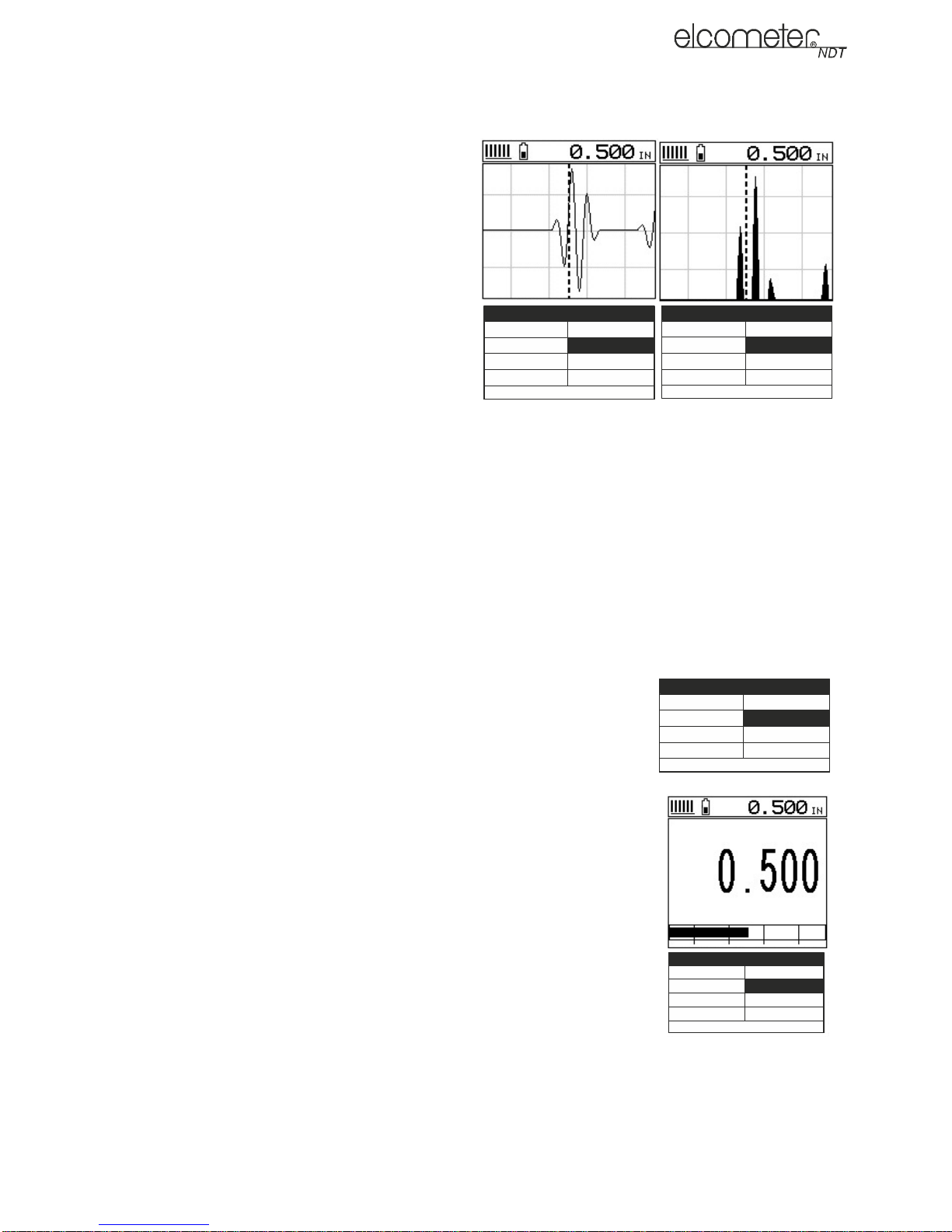
5.2 RF A-SCAN MEASUREMENT SCREEN (CG70ABDL only)
The RF view shows the full sound wave as
received by the gauge. The vertical axis
indicates the amplitude of the received wave
and the horizontal position indicates the time it
is received, which is converted into thickness
units using the material velocity.
The point on the scan that is being used to
calculate the digital thickness reading is
displayed as the vertical dashed line (see
section 9 on gates). The RF screen is used for
gauge setup prior to inspection.
5.3 RECT A-SCAN MEASUREMENT
0.16 0.39 0.61 0.83
0.16 0.39 0.61 0.83
DELAY: 0.00 W IDTH: 1.00
DELAY: 0.00 WIDTH: 1.00
MODE: P-E
MODE : P-E
GATE 1: 0.00 GATE 2: 0.00
GATE 1: 0.00 GATE 2: 0.00
THR: 2
THR: 2
GRID :
GRID :
G AI N : 36
GAIN: 36
LOC: G9
LOC: G9
0.16 0.39 0.61 0.83
DELAY: 0.00 WIDTH: 1.00
MODE : P-E
GATE 1: 0.00 GATE 2: 0.00
THR: 2
GRID :
SCREEN (CG70ABDL only)
The rectified view shows only half of the
waveform, either the positive or negative half depending on the POLARITY selected.
The RECT display is the preferred view for flaw and pit inspections
en
GAIN: 36
LOC: G9
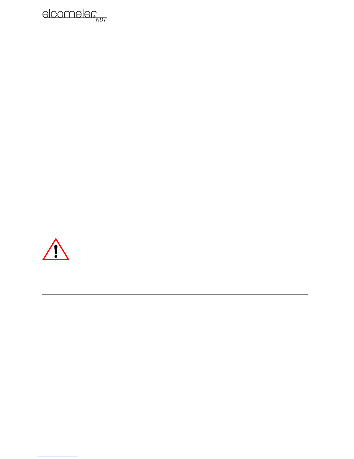
5.4 B-SCAN MEASUREMENT SCREEN
The time-based B-Scan display provides a cross sectional view of the
material being tested. In this example, the top, or accessible side of the
material is represented as 0.00”, and the bottom, or blind surface at
.500”.
This mode is used when you need to inspect the profile of the blind
surface. It can also be a useful view when scanning for pits and flaws.
The B-Scan display is equipped with a scan bar representing the
overall thickness. The scan bar gives the user a visual indication when
a flaw or defect passed over during the scan process.
If you are scanning a pipe, for instance, and pass over a pit during the
process, the scan bar will quickly deflect and alarm you to go back and
search for the defect.
0.16 0.39 0.61 0.83
DELAY: 0.00 WIDTH: 1.00
MODE : P-E
GATE 1: 0.00 GATE 2: 0.00
THR: 2
GRID :
GAIN: 36
LOC: G9
5.5 DIGITS MEASUREMENT SCREEN
The digits display shows the thickness as a value using a large font
size. This view is used typically when the gauge is being used as a
basic thickness gauge. The digits display includes the same scan bar
as the B-Scan display.
5.6 CHANGING THE VIEWABLE RANGE
In RF view, RECT view and B-SCAN view, if the waveform around the
detection point is not visible on the display, use one of the following
methods to adjust the viewable range of the display:
• When in RF view or RECT view, change the values of the DELAY
and WIDTH functions until the measurement falls inside the
0.16 0.39 0.61 0.83
DELAY: 0.00 WIDTH: 1.00
MO D E : P-E
GATE 1: 0.00 GATE 2: 0.00
THR: 2
GRID :
G AI N : 36
LOC: G9
viewable range of the display - see instructions below.
• When in B-SCAN view, change the values of the B-START and B-DEPTH functions until the
measurement falls inside the viewable range of the display. B-START is the equivalent of
DELAY and B-DEPTH is the equivalent of WIDTH and the instructions for changing these
values is identical to those for DELAY and WIDTH - see instructions below.
8

en
• Use the Auto Find function - see ‘Auto Find (CG70ABDL only)” on page 14.
Note: Even if the waveform is outside of the viewable range of the display, a measurement can be
taken and viewed using the DIGITS view.
5.6.1 DELAY AND WIDTH
The DELAY is the thickness value from which the A-Scan display starts on the left of the screen.
The WIDTH is used to adjust the value at the right side of the screen. Using these two parameters
allows the user to zoom in to a specific measurement range and increase the level of detail on the
display. For example, if a wall thickness was nominally 25mm and an operator was assessing for
corrosion on this wall they might set the DELAY to 10mm and the WIDTH to 20mm to fit as much
relevant information on the display as possible.
B-START and B-DEPTH are analogous to DELAY and WIDTH or a B-SCAN display respectively.
DELAY and WIDTH or B-START and B-DEPTH may be adjusted in the hot menu or in the DISP
section of the main menu.
5.6.2 Adjusting DELAY and WIDTH (or B-START and B-DEPTH)
The quickest way to adjust DELAY and WIDTH is directly fr om the hot menu. Alternatively, adjust
the values using the menus:
1. Select MENU/DISP/DELAY or WIDTH and adjust using LEFT and RIGHT or press ENTER to
use the DIGITS EDIT BOX
2. Press OK to set the value
3. Press MEAS to return to the measurement.
5.7 GAIN
The gain (the amplitude of the transmitted pulse) can be adjusted to suit a variety of applications.
To obtain valid readings the gain must be set to the correct level to give reliable return echoes:
• Too much gain may result in erroneous measurements by detecting noise rather than the
material back wall itself.
• Not enough gain may result in intermittent detection. It may also result in lack of detection on
internal flaws, pits, or porosity.
The gain setting on your gauge can be compared to the volume control of a home stereo system.
If you turn it up too much you cannot hear the music clearly. If it is turned down too much, you cannot
hear it at all.
Note: When the echo-echo ThruPaint™ measurement mode is selected, the manual gain feature is
disabled and greyed out in the menu items. In this mode, your gauge switches to an automatic gain
mode (AGC) that optimises the gain setting automatically.
Your gauge has been optimised for a medium gain setting and for the majority of applications it can
be used at this setting. Some applications however may require lower or higher gain settings:
• Lower values might be necessary for noisy or granular cast materials. If the reading becomes
sporadic and will not settle down or resolve on a thickness value.
• Higher values may be necessary when trying to measure a material that is hard to penetra te
(due to the material type, or the overall thickness of the material) and when locating fine pits or
flaws. In these instances, increase the gain until the stability indicator reports a good
measurement.
5.7.1 To Adjust the Gain Value
The quickest way to adjust GAIN is directly from the hot menu. Alternatively, adjust the value using
the menus:
9

1. Select MENU/TUNE/GAIN and adjust using LEFT and RIGHT or press ENTER to use the
DIGITS EDIT BOX
2. Press OK to set the value
3. Press MEAS to return to the measurement screen.
5.8 THRESHOLD (CG70ABDL only)
The threshold is the level of signal amplitude required to trigger a gate and activate the digital
thickness reading. Increasing the threshold value decreases the sensitivity of the gauge as a more
powerful signal is required to trigger the gate. For example on the A-scan display it may be clear
that there is a flaw in the material but the thickness reading is not taking this into account; lowering
the threshold has the effect of increasing the sensitivity of the gauge to a level that the flaw can be
detected. More information on thresholds can be found on the Elcometer NDT Knowledge Centre
on www.elcometerndt.com
5.8.1 To Adjust the Threshold Value
The threshold value may be adjusted from the hot menu when in the P-E GT or E-E measurement
mode.
5.9 GATES (CG70ABDL only)
Your gauge is equipped with gates which control the time measurement process. Further
information on gates can be found on the Elcometer NDT Knowledge Centre on
www.elcometerndt.com.
en
6 MEASUREMENT - MODES
To select the measurement mode, press MULTI MODE until the correct mode is displayed or select
MENU/GATE/MEASURE MODE
Note: The availability of the modes depends upon the type of transducer fitted to the gauge.
6.1 PULSE-ECHO MODE (P-E)
The standard measurement mode providing maximum sensitivity. This general purpose mode
should be used for corrosion and flaw inspections and will measure the total thickness of a material.
6.2 PULSE ECHO WITH GATE MODE (P-E GT) (CG70ABDL only)
Pulse to echo measurement with an adjustable gate for problematic applications. see section 9 on
gates.
6.3 ECHO-ECHO MODE (E-E), THRUPAINT™
This special mode allows the user to measure the material thickness of a substrate underneath a
coating while ignoring the coating thickness by using two echoes from the material back wall. This
mode is useful when the coating thickness makes up a sizeable proportion of a material, but has
the impact of reducing sensitivity so should not be used in pit and flaw inspections.
6.4 FLAW MODE (CG70ABDL only)
The Model CG70ABDL includes a Flaw Mode function which provides basic prove-up flaw detection
using an angle beam transducer. This mode enables inspectors to locate porosity, defects,
inclusions and cracks in a variety of test materials. Further information on the Flaw Mode can be
found on the Elcometer NDT Knowledge Centre on www.elcometerndt.com.
For instructions on how to use the Flaw Mode see ‘Flaw Mode (CG70ABDL only)” on page 16.
10

en
7 SETTING UP THE GAUGE
7.1 SELECTING THE TRANSDUCER TYPE MANUALLY
Follow these steps to select your transducer type.
1. Select MENU/PROBE/TYPE and press ENTER
2. Scroll through the transducer list until the appropriate transducer is
highlighted.
3. Press ENTER to select the transducer.
4. Perform a probe zero
7.2 TRANSDUCER - ZEROING
Setting the zero point for the transducer is important in the same way it
is important for a mechanical micrometer. Zeroing takes into account
slight variations in the manufacturing process for maximum accuracy.
If zeroing is not carried out correctly, the measurements taken by the
gauge will be in error by some fixed value.
To perform a probe zero:
1. Press MEAS to display the measurement screen.
2. Remove all couplant from the face of the transducer and check that the wearface is clean and
free of any debris.
3. Apply a drop of couplant on the transducer and place the
transducer as shown in diagram.
Note: Disregard the value displayed; it is not important. What is
important is accurately performing these steps to ensure reliability
of the zero calculation.
4. Select MENU/PROBE/ZERO TRANSDUCER and press ENTER.
The ZERO TRANSDUCER screen is displayed.
5. Press OK (or ESC to cancel).
When the manual probe zero is completed the measurement
screen is displayed.
6. Remove the transducer from the probe zero disk.
5
Your gauge should now be zeroed.
7.3 CALIBRATING - FOR A MATERIAL
Sound travels through different materials at different speeds, and in
order to measure these materials accurately the correct sound velocity must be programmed into
the gauge. There are three methods of calibrating the gauge.
Known Material Calibration - The material to be measured is selected from a list in the gauge
Known Velocity Calibration - If the material sound velocity is known this may be entered manually
into the gauge.
Known Thickness Calibration - A sample of the material to be inspected is measured using
alternative means and then used to calibrate the gauge.
• One Point calibration is the simplest and most commonly used calibration procedure with best
performance over large measurement ranges
• Two Point calibration uses two samples of different thicknesses, with enhanced accuracy over
small ranges close to the sample thicknesses used
11
0(18
&/5
0($6

For the highest measurement accuracy use the known thickness calibration as this takes into
account variation in material composition, temperature and a variety of other factors.
7.3.1 Known Material Calibration
If the material velocity is unknown, and a sample thickness cannot be taken from the material, you
can choose a material type from a list stored in the gauge. For each material stored in the list there
is a corresponding velocity value.
Note: These velocities will not always be an exact representation of the material being tested. Use
these values only if a close approximation is acceptable.
1. Select MENU/CAL/MATERIAL and press ENTER.
2. Scroll through the material list until the appropriate material is highlighted
3. Press ENTER to select the material type followed by OK.
4. Press MEAS to return to the measurement screen.
7.3.2 Known Velocity Calibration
If the material velocity is known, you can enter the velocity value directly into the gauge. For a list
of the sound velocities of common materials see ‘Sound Velocities of Common Materials” on
page 25
1. Select MENU/CAL/VELOCITY and press ENTER to display the DIGITS EDIT BOX.
2. Adjust to match the material velocity using the LEFT, RIGHT, UP and DOWN arrows then
press OK.
3. Press MEAS to return to the measurement screen.
en
7.3.3 Known Thickness Calibration
If the sound velocity of a material is unknown, a sample with one or two known thicknesses can be
used to determine the sound velocity.
Note: Although the gauge has a ThruPaint™/coating feature, known thickness calibration must be
performed on material with the paint or coating removed.
One-point Calibration: The one point calibration option is most suited for linearity over large
ranges. You should always calibrate on high side of the intended measurement range. For example,
if the measurement range is 2.54 mm to 25.4 mm (.100" to 1.0"), you should calibrate on a known
thickness sample close to 25.4 mm (1.0").
Note: Before you start this calibration procedure, perform a probe zero.
1. Apply a drop of couplant on the transducer and place the transducer in steady contact with the
sample or the material being tested. Be sure that the reading is stable and the repeatability
indicator, in the top left corner of the display, is fully lit and stable.
2. Select MENU/CAL/ONE POINT and press ENTER to display the DIGITS EDIT BOX.
3. Adjust to match the material thickness using the LEFT, RIGHT, UP and DOWN arrows.
4. Press OK to calculate the velocity and return to the measurement screen, or ESC to cancel.
Note: Place the transducer back on the calibration point. The thickness reading should now match
the known thickness but if outside tolerance, repeat the steps above.
Two-point Calibration: For improved accuracy over a smaller measurement range, conduct
one-point calibration followed by a two-point calibration. For example, if the measurement range is
2.03 mm to 6.35 mm (.080" to 0.250"), perform a one point calibration on a known thickness sample
close to 6.35 mm (.250"), followed by a two-point calibration close to 2.03 mm (.080").
Note: Before you start this calibration procedure, perform a probe zero.
12

en
Two - Point calibration
1. Conduct a one point calibration routine as described previously in this section. You should
conduct this routine at the high end of the measurement range
2. Repeat the routine with another sample at the low end of th e mea surement range, exce pt this
time enter the thickness into the TWO POINT area in the CAL menu.
Note: CHECK YOUR CALIBRATION. Place the transducer back on both calibration points. If the
thickness is out of tolerance repeat the steps above.
8 TAKING READINGS
Disclaimer: Inherent in ultrasonic thickness measurement is the possibility that the instrument will
use the second rather than the first echo from the back surface of the material being measured. This
may result in a thickness reading that is TWICE what it should be.
Responsibility for proper use of the instrument and recognition of this phenomenon rests solely with
the user of the instrument.
Other errors may occur from measuring coated materials where the coating is insufficiently bonded
to the material surface. Irregular and inaccurate readings may result. Again, the user is responsible
for proper use and interpretation of the measurements acquired.
8.1 BEFORE YOU START
• Prepare the surface.
• Ensure the correct transducer is selected and set in the gauge.
• Select the correct measurement mode - see ‘Measurement - Modes” on page 10.
• Set the zero point of the transducer - see:
• ‘Transducer - Zeroing” on page 11 and
• Calibrate the gauge - see:
• ‘Calibrating - for a Material” on page 11 and
• Choose the measurement view (DIGITS, RF or RECT, or B-SCAN) - see ‘The Measurement
Screen” on page 6.
8.2 PROCEDURE
1. Apply couplant
For the gauge to work correctly there must be no air gap between the transducer and the
surface of the material to be measured. This is achieved using a couplant.
Before the transducer is placed on the surface, put a small amount of couplant supplied with
the gauge on the surface of the material. Typically a single drop is sufficient.
2. Place transducer onto the surface of the material to be measured
Press the transducer wearface into the couplant. Only moderate pressure is necessary to
keep the transducer stationary and the wearface seated flat against the surface of the
material.
3. Read display
If six or seven bars of the stability indicator are showing, the display will be reading the correct
thickness of the material directly beneath the transducer.
If the stability indicator has fewer than five bars showing, or the numbers on the display seem
erratic, check to make sure that there is an adequate film of couplant beneath the transducer,
and that the transducer is seated flat against the material. If the condition persists, it may be
necessary to:
• adjust the gain, or
• select a different transducer (size or frequency) for the material being measured.
13

The gauge will perform a number of measurements every second when the transducer is in
contact with the surface of the material. The display is updated as each reading is taken.
4. Remove transducer from surface
The display will show the last measurement made.
Note: Occasionally, a small film of couplant will be drawn out between the transducer and the
surface as the transducer is removed. When this happens, the gauge may perform a measurement
through this couplant film. This phenomenon can be seen when one thickness value is observed
while the transducer is in place, and another value is observed after the transducer is remove d. If
this happens, take the reading again using less couplant.
9 GATES (CG70ABDL only)
9.1 INTRODUCTION
The Model CG70ABDL is equipped with gates which control the time measurement process
allowing you to measure a specific region on or between waveforms.
Further information on gates may be found on the Elcometer NDT Knowledge Centre on
www.elcometerndt.com.
en
9.2 ADJUSTING THE GATES
In P-E GT mode one gate is available and may be adjusted from the hot menu. In E-E mode both
gates may be adjusted from the hot menu or alternatively select MENU/GATE.
10 THRUPAINT™ MEASUREMENT T ECHNIQUE
10.1 INTRODUCTION
Your gauge is equipped with a ThruPaint
technique to allow measurement of the material thickness beneath a coating. This is useful for
checking the material thickness of painted object.
ThruPaint
measurement mode using the MULTI MODE key.
Special "High Damped" or Coating Thickness transducers are required for this mode to function.
Further information may be found on the Elcometer NDT Knowledge Centre on
www.elcometerndt.com.
™ capability is available in E-E mode, to activate ThruPaint™ operation select this
™ measurement mode that uses a multiple echo
11 MEASUREMENT - OPTIONS
11.1 AUTO FIND (CG70ABDL only)
When using a scan type display, the DELAY and WIDTH (or B-START and B-DEPTH) must be set
correctly for the waveform to be shown on the display. If these parameters are set up incorrectly
nothing will be seen. The AUTO FIND function solves this problem by automatically adjusting these
parameters so that the relevant part of the waveform is shown on the screen.
To use the AUTO FIND function place the transducer on the material to obtain a reading, select
MENU/UTIL/AUTO FIND.
11.2 HIGH SPEED SCAN
Although your gauge excels at making single point measurements, it is sometimes desirable to
examine a larger region, searching for the thinnest point. The gauge includes a feature, called Scan
Mode, which allows it to do just that.
14

en
This mode increases the overall repetition rate to a maximum of 32 Hz with a high speed screen
refresh rate of 25 times a second.
This feature enables the user to make scanned passes over an arbitrary length of the test material
while still maintaining a reasonable representation of thickne ss over the scanned area or region.
This feature can be used in conjunction with High and Low alarm limit s features to keep track of
both values dynamically.
To enable/disable the high speed Scan Mode:
1. Select MENU/UTIL/SCAN MODE.
2. Use the LEFT and RIGHT arrows to toggle the SCAN MODE on/off.
3. Press MEAS to return to the measurement screen, ready to begin taking readings.
11.3 ALARM MODE
Your gauge includes an Alarm Mode. Set the limits, and if a measurement falls outside of these
limits your gauge will signal an alarm (a red light on the front panel of the instrument and/or an
audible beep).
This feature may be used for a variety of applications to verify the material is within the manufacturer
specifications.
There are two limit values, ALARM LOW and ALARM HIGH. You can choose to activate both or
just one of these values depending on your requirements.
To enable/disable Alarm Mode:
1. Select MENU/UTIL/ALARM STATUS
2. Use the LEFT and RIGHT arrows to toggle the ALARM on/off/audible.
3. Press MEAS to return to the measurement screen, ready to begin taking readings.
To set the Alarm limits:
1. Select MENU/UTIL/ALARM LO LIMIT or ALARM HI LIMIT and press ENTER to display the
DIGITS EDIT BOX.
2. Adjust to suit the measurement application using the LEFT, RIGHT, UP and DOWN arrows.
3. Press OK to set the alarm value and return to the menu screen, or ESC to cancel.
4. Press MEAS to return to the measurement screen.
11.4 POLARITY (CG70ABDL only)
The polarity that your gauge detects on can be set to either positive or negative to obtain the best
detection results depending on the specific measurement conditions of your application. Polarity
affects both the gate (above or below the x axis in the RF A-Scan) and the Rectified A-Scan display
(whether the top or bottom half of the RF display is shown).
For further information refer to the Elcometer NDT Knowledge Centre on www.elcometerndt.com.
To adjust POLARITY:
1. Set the measurement screen view to RF, MENU/DISP/VIEW.
2. Select MENU/TUNE/POLARITY.
11.5 PULSE WIDTH (CG70ABDL only)
Your gauge has an adjustable pulse width option. Pulse width refers to the duration o f time the
pulser is switched on. Pulse width determines the amount of energy transmitted into the material
being tested.
There are three pulse width options:
15

Spike: The Spike option is used for high resolution and general applications and can be considered
as the standard setting.
Thin: When additional energy is needed for more penetration, the Thin option may be necessary.
Wide: When even more energy is needed for more penetration, the Wide option may be necessary.
High frequency applications, where resolution is a requirement, may require the Spike or Thin
settings to achieve optimal results. Low frequency applications, where more penetration is a
requirement, may require the Thin or Wid e settings, offering incr eased penetration. The variety of
transducer frequencies and diameters used in conjunction with the pulse width setting, enable you
to fine tune the gauge to your application needs.
To adjust the Pulse setting:
Select MENU/PROBE/PULSE
12 FLAW MODE (CG70ABDL only)
12.1 INTRODUCTION
Your gauge includes a basic flaw prove up mode. Further in formation on flaw detection can be
found on the Elcometer NDT Knowledge Centre on www.elcometerndt.com.
en
12.2 FLAW MODE VIEW
Feature Description
A
Horizontal gridlines on the display represent
increments of 25% of the full screen height
The thickness reading normally occupying
B
this space is not relevant to flaw detection. It
is replaced by a dashed line
The peak hold symbol is only visible when
flaw mode is set to peak. Indicates the high-
C
est amplitude reflection detected during a
scan. Pressing CLR will reset the position of
the peak hold symbol to zero
Vertical gridlines on the labelled with quad-
D
rant numbers. Unlike thickness mode they do
not correspond to the material thickness
12.3 ENABLING FLAW MODE
To use Flaw Mode, an angle beam transducer and dual lemo to single microdot cable are required.
These are available from Elcometer NDT.
1. Attach the dual lemo to microdot cable and angle beam transducer to the gauge.
2. Select MENU/PROBE/FLAW MODE
3. Use the LEFT and RIGHT arrows to adjust the value of the FLAW MODE function (OFF, ON,
PEAK):
• OFF - Disables Flaw Mode
• ON - Enables Flaw Mode
16

en
• PEAK - Enables the Flaw Mode and Peak Hold options and view. When this option is
enabled, the peak hold symbol is displayed on the right side of the display (to reset to
zero, press CLR).
4. Press MEAS to return to the measurement screen.
Note: When flaw mode is activated, a transducer delay will still be configured from the previously
loaded transducer. This will only affect the position of the starting point from the initial pulse. The
zero delay can be set to zero by loading the default setup located in the setup menu. Alternatively,
you can load a factory flaw mode setup, and begin making any adjustments necessary.
13 MEASUREMENT - RECORDING YOUR READINGS
Your gauge is equipped with a data logger. With a data file open, all your measurements are saved
into the file for later review and download to PC.
13.1 ABOUT THE DATA LOGGER
With a data file open, as you take measurements, the measurement data is stored in files in the
gauge memory in Grid format similar to a spreadsheet format in which each cell is used to store a
reading. Cells are referenced by the row number (1 to 999) and the column label (A to ZZ).
Data logger filename character sets
Any combination of the following characters can be used for file names:
• Numeric characters: 0 - 9
• Alpha Characters: A - Z
• Special Characters: ! ' _ # space / . - ( )
What measurement data is saved
When a measurement is taken (irrespective of log file format), the following information is saved:
• The reading value.
• A screenshot, the nature of which will depend on what view the gauge was in at the time the
reading was taken. For example, if the view was in B-SCAN, then a B-SCAN screenshot will
be saved with the reading. This 'Save Graphics' option can be toggled on/off.
Memory capacity
You can create and save as many data files as required up to the maximum capacity of the gauge
memory (32 Mbit). If you try to create a new file which exceeds the memory capacity, the gauge will
display an error message. Saved data must be deleted in order to make the space available.
.
Save Graphics Option
Memory Capacity
(readings)
On 12 000 +
Off 210 000 +
13.2 CREATING A NEW DATA LOGGER FILE - GRID FORMAT
To create a GRID log data file:
1. Select MENU/DATA/NEW and press ENTER to continue
2. Fill in a name and a note (if desired) for your data logger file
3. Select the size of the grid. Grid positions are denoted by a number and a letter, where the
letter is the column and the number is the row.
Use TOP LEFT and LOWER RIGHT to define the size of the grid. For example, a with the TOP
LEFT set to A001 and LOWER RIGHT C003 would produce a 3x3 grid
17

The grid can have a maximum of 52 columns and 999 rows
4. Set the Auto Increment direction. This option allows you to select which direction the cursor
moves after a reading is stored in terms of compass points. For example NORTH would move
the cursor up a row, and WEST would move a column left.
5. Choose whether to activate SAVE GRAPHICS or not (snapshot of the A OR B scan on
screen).
6. Finally create the log by scrolling to CREATE LOG, pressing ENTER and then OK to confirm.
The measurement grid is now displayed along with the grid name on screen.
13.3 HANDLING LOGGER FILES
Once created, logger files may be opened or closed using the functions "OPEN" and "CLOSE"
Closing logger files places the gauge in immediate mode and will prevent accidental saving of data
into an inappropriate log.
13.4 STORING READINGS IN A DATA LOGGER FILE
1. Create a new data logger file or open an existing file.
The grid is displayed in the lower half of the measurement screen.
Note: Once the file is open, it will remain open until it is closed or another file is opened. If the
gauge is switched off, the file will be opened automatically when the gauge is switched on
again. Press the ENTER key to display the file from the measurement screen.
2. If you want to save the reading to a particular cell location, scroll to the desired cell.
Note: The cell location must be empty. If it already contains a reading and you want to save a
new reading to the same location, refer to the instructions given in ‘Viewing and Deleting
readings” on page 18.
3. Take a reading and then press ENTER.
The reading value is saved in the file at the location selected and the cursor advances to the
next cell according to the rules set for the data logger file:
• If INCR. DIR is set to NORTH, EAST, SOUTH or WEST, the cursor will advance one cell in
the chosen direction. When the cursor reaches the last cell in the row or column it will
return to the other end of the row or column.
Note: If you try to save a reading into a cell location which already contains a reading value, a
warning message is displayed (see Deleting a reading).
4. To advance to a specific row number, press OK enter the row number. Press OK to advance
directly to that row number in the grid log.
5. To toggle the display between DIGITS view and B-SCAN view, press ESC.
6. If you are unable to take a measurement due to the measurement location being physically
inaccessible, press CLR.
The cell location in the data file is marked OBST (Obstruct).
7. The display of the log data file on the measurement screen can be switched on and off:
• To switch off, press MEAS
• To switch on, press ENTER.
en
13.5 VIEWING AND DELETING READINGS
With a data file open:
1. Use the arrows to scroll through the cells in the data file.
As the cursor is moved to a different cell, the display is updated with the display view saved
with the reading (if SAVE GRAPHICS was set to YES). Readings stored in memory are
indicated by MEM in the top left corner of the measurement screen (in place of the bars of the
stability indicator).
18

en
2. To delete a reading, scroll to the cell location, press CLR and then OK (or ESC to cancel).
The reading is deleted and if you wish you can now take another measurement and save the
reading in this cell location.
13.6 EDITING A DATA LOGGER FILE
You can edit the following fields of data files:
• NAME, NOTE, and INCRement DIRection
To edit a file:
1. Open the data file. (Select MENU/DATA/OPEN)
2. Select MENU/DATA/EDIT and press ENTER
The EDIT GRID screen is displayed and lists all the fields which can be edited.
3. Scroll to the field you want to edit, press ENTER and then adjust the contents of the field using
the techniques previously described to create a data file - see page 17.
4. When finished, scroll to SAVE CHANGES, press ENTER and then OK (or ESC to cancel).
13.7 DELETING A DATA LOGGER FILE
1. Select MENU/DATA/DELETE ONE GRID and press ENTER.
The DELETE GRID screen is displayed and lists all the data files stored in your gauge
memory.
2. Scroll through the list until the data file you want to delete is highlighted.
3. Press OK (or ESC to cancel).
The file is deleted.
13.8 DELETING ALL DATA LOGGER FILES
Note: This will delete all the data logger files in gauge memory - use with caution.
1. Select MENU/DATA/DELETE ALL GRIDS
2. Press ENTER and then OK to confirm (or ESC to cancel).
The data logger memory is erased - all files are deleted.
14 GAUGE SETUPS
Your gauge contains 64 configurable preset locations in which you can store custom gauge setups,
each one optimised for a specific measuring application.
These gauge setups can save time when conducting routine inspections of the same job or project.
This feature also helps to eliminate error between two or more users during the setup and
calibration process.
The setups store:
• Measurement mode
• Transducer type
• Gain setting
• Scan mode setting
• Alarm settings
• Display type setting
As well as storing the setups in your gauge, you can also store the setups on a computer and
transfer them bi-directionally using the PC interface software included with the gauge.
The factory supplied setups stored in the gauge cover some of the more typical applications
commonly used with this type of instrument and may be modified freely by the user.
The PC interface software includes a default setup file that can be uploade d to the gauge at any
time to restore factory settings. However, you should consider saving modified setups to an empty
location rather than overwriting the factory setups in your gauge.
19

14.1 OPENING A SETUP
1. Select MENU/SETUP/OPEN and press ENTER to display the SETUP
LIST BOX.
2. Scroll through the list of setups until the required setup is highlighted.
3. Press ENTER to activate the confirmation screen.
4. Press OK to load the setup from memory.
5. Press MEAS to return to the measurement screen.
14.2 SAVING AND EDITING A SETUP
Once the parameters and features have been adjusted for an application,
you can save these setting to a specific setup location for future use.
It is sometimes necessary to rename a previously saved setup, or add
additional comments about a particular setup. The other comments about the project may also be
required for additional documentation purposes.
The following procedures outline the necessary steps for saving and editing a setup:
1. Select MENU/SETUP/SAVE and press ENTER to display the SAVE SETUP EDIT BOX.
2. Scroll to NAME and then press ENTER to edit its value:
• When you have finished, press OK to enter the value.
3. If you want to add a note, repeat step 2 for NOTE.
4. When you have finished, scroll to SAVE SETUP and press ENTER.
The setup list screen is displayed.
5. Scroll through the list of setups until the required location to save the
setup is highlighted.
6. Press OK to activate the confirmation screen.
7. Press OK to save the SETUP, or ESC to cancel.
en
Note: The Name and Note parameters of a Setup can be edited at any time
by repeating the Save Setup routine described above. Therefore, the Save
Setup function can also be considered an Edit Function.
14.3 USING THE DEFAULT SETUP
Your gauge includes a default setup which you can use (as a last resort) if
there are no other setups stored in the gauge. This gives you the ability to
load and modify a basic setup as follows:
1. Select MENU/SETUP/DEFAULT SETUP and press ENTER to activate the confirmation
screen.
2. Press OK to confirm.
3. Press OK again to confirm.
15 DATA TRANSFER SOFTWARE
Software is available which allows data to be transferred from your gauge to a PC. Presently
Elcometer supplies ElcoMaster 2.0™ software for this purpose.
To set-up other types of communications software:
1. Start the communications software.
2. Configure the software using the following parameters:
Data Bits - 8, Parity - None, Stop Bits - 1, Baud Rate 1200 (to print a report), or 9600 to
transfer data file.
Note: A report can be printed to a communications program (i.e. HyperTerminal), or printed to
a serial printer using A4 or 8.5" x 11" paper.
20
en
3. Set the communications software COM port to the port number that the gauge is connected to.
15.1 TRANSFERRING MEASUREMENT DATA TO YOUR COMPUTER
15.1.1 RS-232 Connector
The RS-232 connector, located on the bottom end cap of the gauge, is a 2 pin female Lemo
connector. It is designed to connect directly from the gauge to a standard AT serial port on a PC. A
Lemo to 9 pin serial cable is supplied with the gauge.
Note: This connector is also used to upgrade the gauge with the latest version of firmware.
15.1.2 USB to Serial Converter
Some newer laptop computers do not have standard serial ports. In this case, use the USB to Serial
converter supplied with the gauge.
15.1.3 Computer System Requirements
ElcoMaster 2.0™ is compatible with any Windows computer system running Windows XP or above.
15.1.4 Using the XFER menu
The XFER menu of your gauge is used in conjunction with the ElcoMaster 2.0™ PC software. The
steps below outline the procedure for accessing the XFER menu and basic operation as fo llows:
1. Scroll to the XFER section of the main menu.
2. Press the ENTER key to activate the option selected.
3. Once the Backup or Restore function has been completed, press the MEAS key once to return
to the menu items, or twice to return to the measurement mode.
16 STORAGE
Your gauge has a Liquid Crystal Display. If the display is heated above 50°C (120°F) it
may be damaged. This can happen if the gauge is left in a car parked in strong sunlight.
Always store the gauge in its case when it is not being used.
If the gauge is to remain unused for long periods of time, remove the batteries and store
them separately. This will prevent damage to the gauge in the event of malfunction of
the batteries.
17 MAINTENANCE
You own one of the finest corrosion gauges in the world. If looked after, it will last a lifetime.
17.1 FAULTS
Your gauge is designed to give many years reliable service under normal operating and storage
conditions. The gauge does not contain any user-serviceable components. In the unlikely event of
a fault, the gauge should be returned to your local Elcometer NDT supplier or directly to Elcometer
NDT. The warranty will be invalidated if the instrument has been opened.
17.2 TRANSDUCER
The transducer will wear with repeated use. To extend transducer life, always set the transd ucer
down so that it is perpendicular to the panel surface. Dragging the transducer along the surface will
reduce the life of the transducer. Replacement transducers are available from your local Elcometer
NDT supplier or directly from Elcometer NDT.
21
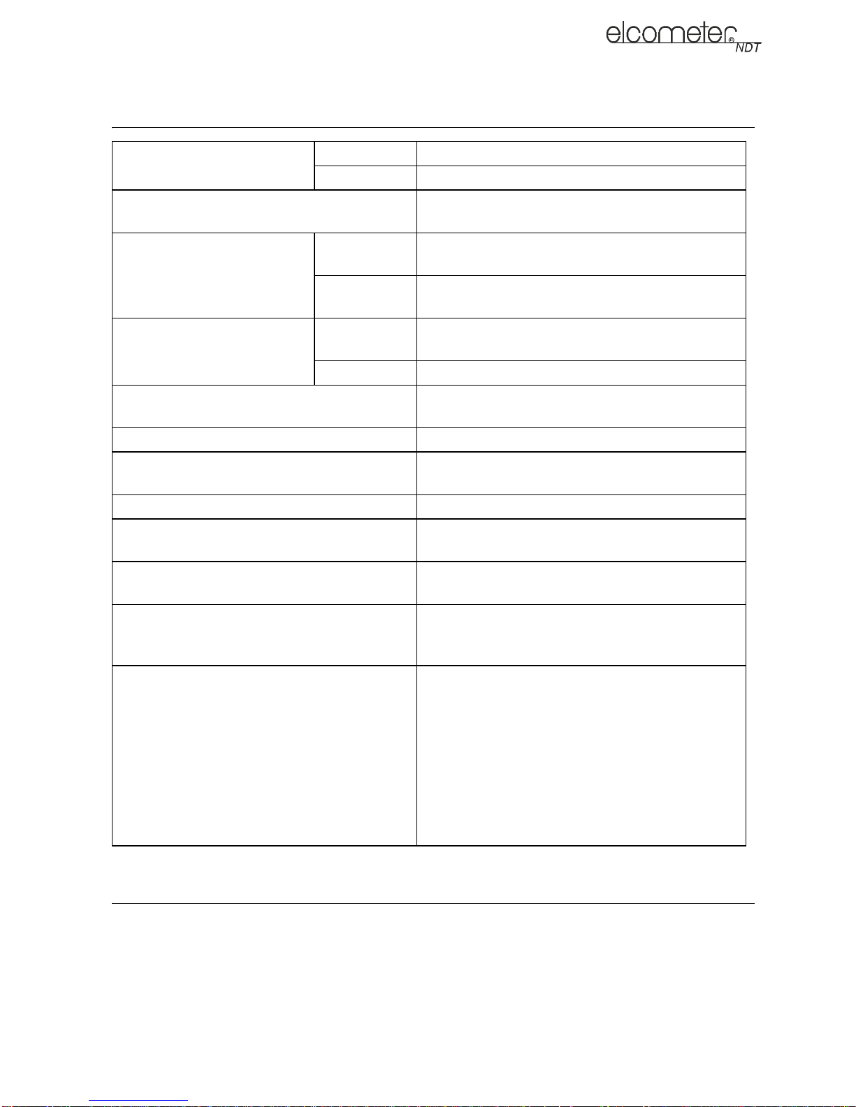
18 TECHNICAL SPECIFICATION
en
Measurement Rate
Manual 4 readings per second
Scan mode 32 readings per second
a
Measuring Range
- Sound Velocity
Measuring Range Thickness
Measurement Resolution
Pulse-Echo
P-E
Echo-Echo
E-E
Sound
Velocity
1250 m/s to 10000 m/s (0.0492 in/µs
in/µs)
0.63 mm to 254 mm (0.025” to 9.999”)
2.54 mm to 102 mm (0.1” to 4.0”)
Range will vary +/- depending on the coating.
1 m/s (0.0001 in/µs)
Thickness 0.01 mm (0.001")
Velocity Calibration Range
1250 m/s to 10000 m/s (0.0492 in/µs
in/µs)
Weight (including batteries) 380 g (13.5 oz)
Dimensions (W x H x D)
63.5 mm x 165 mm x 31.5 mm (2.5” x 6.5” x
1.24”)
Gauge Operating Temperature -10°C to 60°C (14°F to 140°F)
Case
Aluminium case with gasket sealed end caps and
waterproof membrane keypad
to 0.3930
to 0.3937
PC Connection
RS232 serial port. Windows PC interface
software
Backlit VGA greyscale display (240 x 160 pixels).
Display
Viewable area 62 mm x 45.7 mm (2.4” x 1.8”). EL
backlit (on/off/auto).
Three 1.5V AA alkaline or 1.2V rechargeable
cells. Typically operates for 200 hours on alkaline
and 120 hours on rechargeable cells (charger not
included.)
Power Source
Note: Alkaline batteries must be disposed of
carefully to avoid environmental contamination.
Please consult your local environmental authority
for information on disposal in your region. Do not
dispose of any batteries in fire.
a. Measuring Range depends on material, surface conditions and the transducer selected.
19 WARRANTY
Elcometer NDT warrants your gauge against defects in materials and workmanship for a period of
two years from receipt by the end user.
Additionally, Elcometer NDT warrants transducers and accessories against such defects for a
period of 90 days from receipt by th e end user. If Elcometer NDT receives notice of such defects
during the warranty period, Elcometer NDT will either, at its option, repair or replace products that
prove to be defective. The warranty will be invalidated if the instrument has been opened.
22

en
19.1 EXCLUSIONS
The above warranty shall not apply to defects resulting from: improper or inadequate maintenance
by the customer; unauthorised modification or misuse; or operation outside the environmental
specifications for the product.
Elcometer NDT makes no other warranty, either express or implied, with respect to this product.
Elcometer NDT specifically disclaims any implied warranties of merchantability or fitness for a
particular purpose. Some states or provinces do not allow limitations on the duration of an implied
warranty, so the above limitation or exclusion may not apply to you. However, any implied warranty
of merchantability or fitness is limited to the two-year duration of this written warranty.
This warranty gives you specific legal rights, and you may also have other rights, which may vary
from country to country, state to state or province to province.
19.2 OBTAINING SERVICE DURING WARRANTY PERIOD
If your hardware should fail during the warranty period, contact Elcometer NDT and arrange for
servicing of the product. Retain proof of purchase in order to obtain warranty service.
For products that require servicing, Elcometer NDT may use one of the following methods:
• Repair the product
• Replace the product with a re-manufactured unit
• Replace the product with a product of equal or greater performance
• Refund the purchase price.
19.3 AFTER THE WARRANTY PERIOD
If your hardware should fail after the warranty period, contact Elcometer NDT for details of the
services available, and to arrange for non-warranty service.
20 SPARES & ACCESSORIES
20.1 TRANSDUCERS
Elcometer NDT gauges are not
separately.
The transducers listed below are the most commonly used however, Elcometer NDT offer a wide
range of other transducers to suit various applications.
Further information on the transducers available and their applications can be found on the
Elcometer NDT Knowledge Centre on www.elcometerndt.com.
Description Sales Part No.
2.25 MHz 1/4” Potted Side Transducer TX2M25CP-2
5 MHz 1/4” Potted Side Transducer TX5M00CP-4
5 MHz 1/4” P otted Side High Damped Transducer TX5M00CP-10
7 MHz 1/4” P otted Side High Damped Transducer TX7M50CP-6
10 MHz 1/4” Potted Side Transducer TX10M0CP-4
Dual Lemo to Single Microdot Transducer Cable TL-24030-8
2.25 MHz 1/4” Microdot Side Mini Angle Beam Transducer, 45 Degree TF2M25C45M
5 MHz 3/8” Microdot Side Mini Angle Beam Transducer, 60 Degree TF5M00D60M
10 MHz 3/16” Microdot Side Mini Angle Beam Transducer, 70 Degree TF10M0B70M-1
supplied with a transducer as standard - this must be ordered
20.2 CALIBRATION BLOCKS
Elcometer NDT offer a comprehensive range of calibration blocks to suit a wide range of
applications and standards.
23

Selecting the correct calibration block for the application is essential to ensure accurate evaluation.
The form, shape and material of the calibration block should be appropriate for the material being
inspected. Any artificially induced flaw should closely resemble that of the actual flaw being tested
for.
The calibration blocks listed below are a selection of those available - details of the full range can
be found on www.elcometerndt.com
Description Sales Part No.
Calibration Block: 8 Step; 1 - 8mm TW-24005-*
Calibration Block: 10 Step; 2 - 20mm TW-24006-*
Calibration Block: 10 Step; 2.5 - 25mm TW-24007-*
Replace * with S1018 = 1018 Steel Block; A = Aluminium Block; SS = Stainless Steel Block;
T = Titanium Block.
20.3 ULTRASONIC COUPLANT
Each gauge is supplied with a 120ml (4oz) bottle of standard ultrasonic couplant. Replacement
bottles and couplant for high temperature applications are available from your local Elcometer NDT
supplier or directly from Elcometer NDT.
Description Sales Part No.
Ultrasonic Couplant, 120 ml (4 oz) TC-24034-1
Ultrasonic Couplant, 360 ml (12 oz) TC-24034-2
Ultrasonic Couplant, High Temperature 343°C (650°F), 120 ml (4 oz) TC-24034-4X
Ultrasonic Couplant, High Temperature 482°C (900°F), 120 ml (4 oz) TC-24034-5X
en
Note: A wide range of other transducers and accessories is available - see www.elcometerndt.com
for details.
21 CONDITION AND PREPARATION OF SURFACES
Further information can be found on the Elcometer NDT Knowledge Centre on
www.elcometerndt.com.
22 APPLICATION
Further information can be found on the Elcometer NDT Knowledge Centre on
www.elcometerndt.com.
24

en
23 SOUND VELOCITIES OF COMMON MATERIALS
Material
Aluminium 6350 0.250 Paraffin 2210 0.087
Bismuth 2184 0.086 Platinum 3962 0.156
Brass 4394 0.173 Plexiglas 2692 0.106
Cadmium 2769 0.109 Polystyrene 2337 0.092
Cast Iron 4572 0.180
Constantan 5232 0.206 PVC 2388 0.094
Copper 4674 0.184 Quartz Glass 5639 0.222
Epoxy Resin 2540 0.100
German Silver 4750 0.187 Silver 3607 0.142
Glass, Crown 5664 0.223 Steel 5918 0.233
Glass, Flint 4267 0.168 Steel, Stainless 5664 0.223
Gold 3251 0.128 Stellite 6985 0.275
Ice 3988 0.157 Teflon 1422 0.056
Iron 5893 0.232 Tin 3327 0.131
Lead 2159 0.085 Titanium 6096 0.240
Magnesium 5791 0.228 Tungsten 5334 0.210
Mercury 1448 0.057 Water 1473 0.058
Nickel 5639 0.222 Zinc 4216 0.166
Nylon 2591 0.102
Sound velocity
(m/s) (in/µs) (m/s) (in/µs)
(Approx.)
(Approx.)
(Approx.)
Material
Porcelain 5842 0.230
Rubber, Vulcanised
Sound velocity
(Approx.)
2311 0.091
(Approx.)
24 THE MENU COMMANDS
Note : Certain menu commands are not accessible on some CG70 models
Menu Function Description
PRB
(PROBE)
ZERO
TRANSDUCER
Zeros your gauge in much the same way that a mechanical
micrometer is zeroed. If your gauge is not zeroed correctly,
all of the measurements made may be in error by some
fixed value.
TYPE Use this function to select the type of transducer being
used from a chart of transducer types. This provides
increased linearity between transducers.
FLAW MODE Activates the flaw detection mode and view. This feature is
for use with single element angle beam transducers and
used as a general prove-up flaw inspection mode.
PULSE Your gauge has adjustable pulse width for both high
penetration and resolution applications. The pulse width
refers to the duration of time the pulser is on. The options
are SPIKE, THIN, and WIDE.
25

Menu Function Description
en
CAL
(CALIBRATION)
DISP
(DISPLAY)
MATERIAL Select the material velocity from a chart of basic material
types when a known sample thickness, or material velocity
cannot be obtained.
ONE-POINT Performs a single point calibration. This function allows you
to automatically calculate the velocity by entering a known
sample thickness.
TWO-POINT Performs a two-point calibration. This function allows you to
automatically calculate the velocity by entering a second
known sample thickness.
UNITS Toggle between Metric (millimetres) or English (inches)
units.
VELOCITY This function calibrates your gauge by setting the velocity
to a known material velocity.
VIEW Choose between RF wave, RECT (rectified) wave, BSCAN
(cross section), and DIGITS (large digits) views.
DELAY
(B-START)
RANGE
(B-DEPTH)
Adjust where the left side of the display window starts
according to thickness, in inches or millimetres.
Set the overall depth of the viewable measurement area. It
functions a lot like a zoom on a camera.
CONTRAST Adjusts the contrast of the display
BACKLIGHT Select backlight option of OFF, ON or AUTO. In AUTO
mode the backlight is only switched on when the gauge is
making a measurement.
TUNE POLARITY The gauge operates on a zero crossing detection principle.
This feature toggles which stroke of the cycle the crossing
detection uses, either positive or negative.
GAIN Increases or decreases the overall amplitude of the signal.
Gain is similar to the volume control on a stereo receiver.
AGC When operating in E-E mode, the gauge adjusts the gain
automatically. Alternatively, the AGC can be manually
controlled.
GATE GATE 1 Sets the start of the gate, according to time/distance.
GATE 2 Set the start position of gate 2 (E-E mode only)
MEASURE
Select the measurement mode.
MODE
SET UP OPEN Displays a list of factory and user-defined setups currently
stored in memory. These setups can be recalled and used
at any time.
SAVE Save a custom setup that you have modified or created.
DEFAULT
SETUP
Loads a basic default setup. Use only as a last resort if the
setups in your gauge have been corrupted and a computer
is not accessible.
LANGUAGE Select the menu language
26

en
Menu Function Description
DATA NEW Creates a new alpha numeric grid. You can customise the
grid file according to your requirements.
EDIT Modify the parameters of grid files previously saved.
Note: Predefined coordinates cannot be changed once they
have been created.
OPEN Recalls existing grids files from gauge memory.
UTIL
(UTILITIES)
XFER
(TRANSFER)
DELETE ONE
Deletes a selected grid file from memory.
GRID
DELETE ALL
Deletes all files currently stored in memory.
GRID
AUTO FIND Automatically locates the detection point if the
measurement is out of the viewable display area.
SCAN MODE Enables a high speed scan mode that increases the overall
sample rate from 24 to 50 measurements per second,
depending on the current measurement mode used.
ALARM
Toggles alarm mode ON, OFF, or AUDIBLE.
STATUS
ALARM HIGH Sets the HI limit parameter. If the measurement exceeds
this value, a red light will illuminate and the alarm will
sound.
ALARM LOW Sets the LOW limit parameter. If the measurement falls
below this value, a red light will illuminate and the alarm will
sound.
BACKUP
SETUPS
RESTORE
SETUPS
Allows you to backup the setups currently stored in your
gauge to a computer via the RS232 port.
Allows you to restore setups saved on a computer to your
gauge via the RS232 port.
BACKUP GRID Allows you to backup grids files stored in your gauge to a
RESTORE
GRID
ABOUT Provides Elcometer NDT contact information and your
27
computer via the RS232 port.
Allows you to restore grids files saved on a computer to
your gauge via the RS232 port.
gauge software version.
Refer to the help section of your gauge NDT Link software
for a complete electronic manual covering data transfer.

26 INDEX
A
Adjusting the Gates 14
Alarm 15
Auto Find 14
B
Batteries 5
B-SCAN Measurement Screen 8
C
Calibration 11
Calibration One Point 12
Coating Calibration 12
Couplant 13
Cut/Boost 15
D
Data logger 17
Default Setup 20
Delay 9
Deleting readings 18
Digits Measurement Screen 8
Display 6
E
Echo - Echo (E-E) 10
F
Flaw Mode 16
G
Gates 10
Gauge Setups 20
Grid Log 17
O
One Point calibration 11
P
Packaging 4
Peak 17
Polarity 15
Probe Zero 11
Pulse - Echo (P-E) 10
Pulse Width 15
Pulse-Echo Coating (PECT) 10
R
RECT A-Scan Measurement Screen 8
Reset 20
RF A-Scan Measurement Screen 8
S
Saving Data 17
Scan Mode 15
Selecting menu language 6
Spike Pulse 16
Stability Indicator 7
stability indicator 13
Switching On/Off 5
T
Thin Pulse 16
Threshold 10
ThruPaint™ 10
Transducer 5
Transducer delay line 13
Tuning 15
Two Point Calibration 11
H
High Speed Scan 14
K
Known Material Calibration 12
M
Measurement Modes 10
Measurement Procedure 13
Measurement Screens 7
Memory 17
28
V
Viewable Range 8
Viewing Readings 18
W
Wide Pulse 16
Z
Zeroing 11
 Loading...