


User Guide
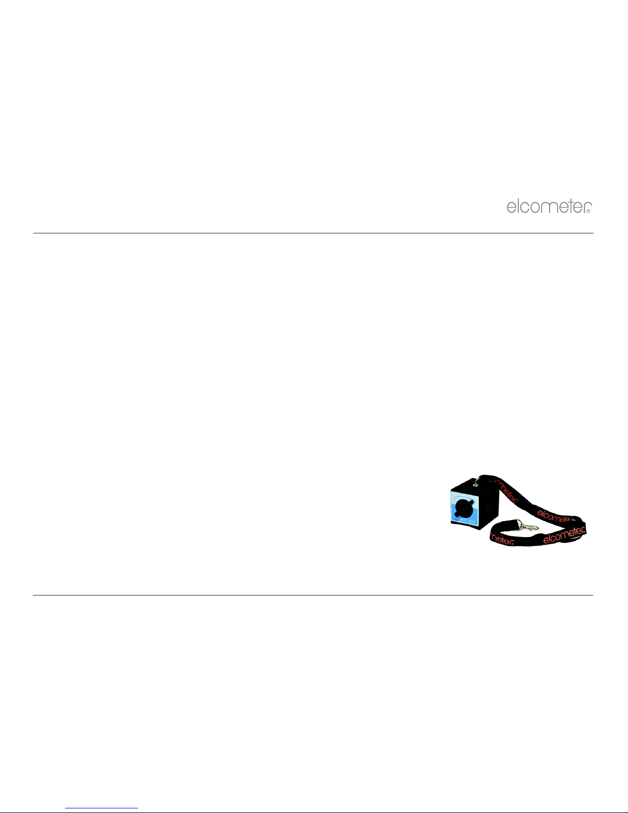
Elcometer 510 Model S
Automatic Adhesion Tester
en
R
www.elcometer.com

1
Gauge Overview
10
Reviewing Batch Data
2
Box Contents
11
Verifying the Gauge Calibration
3
Using the Gauge
12
Menu Structure
4
Getting Started
13
Downloading Data & Upgrading Your Gauge
5
Securing the Dolly
14
Spares & Accessories
6
Attaching the Gauge to the Dolly
15
Adhesives
7
Performing the Test
16
Technical Specification
8
Assessing the Results
17
Legal Notices & Regulatory Information
9
Batching
en
R
www.elcometer.com
For the avoidance of doubt, please refer to the original English language version.
Gauge Dimensions: 260 x 100 x 66mm (10.3 x 3.9 x 2.6").
Gauge Weight: With 10mm, 14.2mm & 20mm Standard Dolly Skirt: 2.9kgs (6.4lbs); With 50mm Standard Dolly Skirt: 3.1kgs (8.3lbs)
Note: Compliance can only be assured if approved accessories are used with this product.
© Elcometer Limited 2014. All rights reserved. No part of this document may be reproduced, transmitted, transcribed, stored (in a retrieval system or otherwise) or translated into any
language, in any form or by any means (electronic, mechanical, magnetic, optical, manual or otherwise) without the prior written permission of Elcometer Limited.
TMA-0595 Issue 02 - Text with cover 24603
Pb
Hg
CONTENTS
1 GAUGE OVERVIEW
www.elcometer.com
2
en
R
a
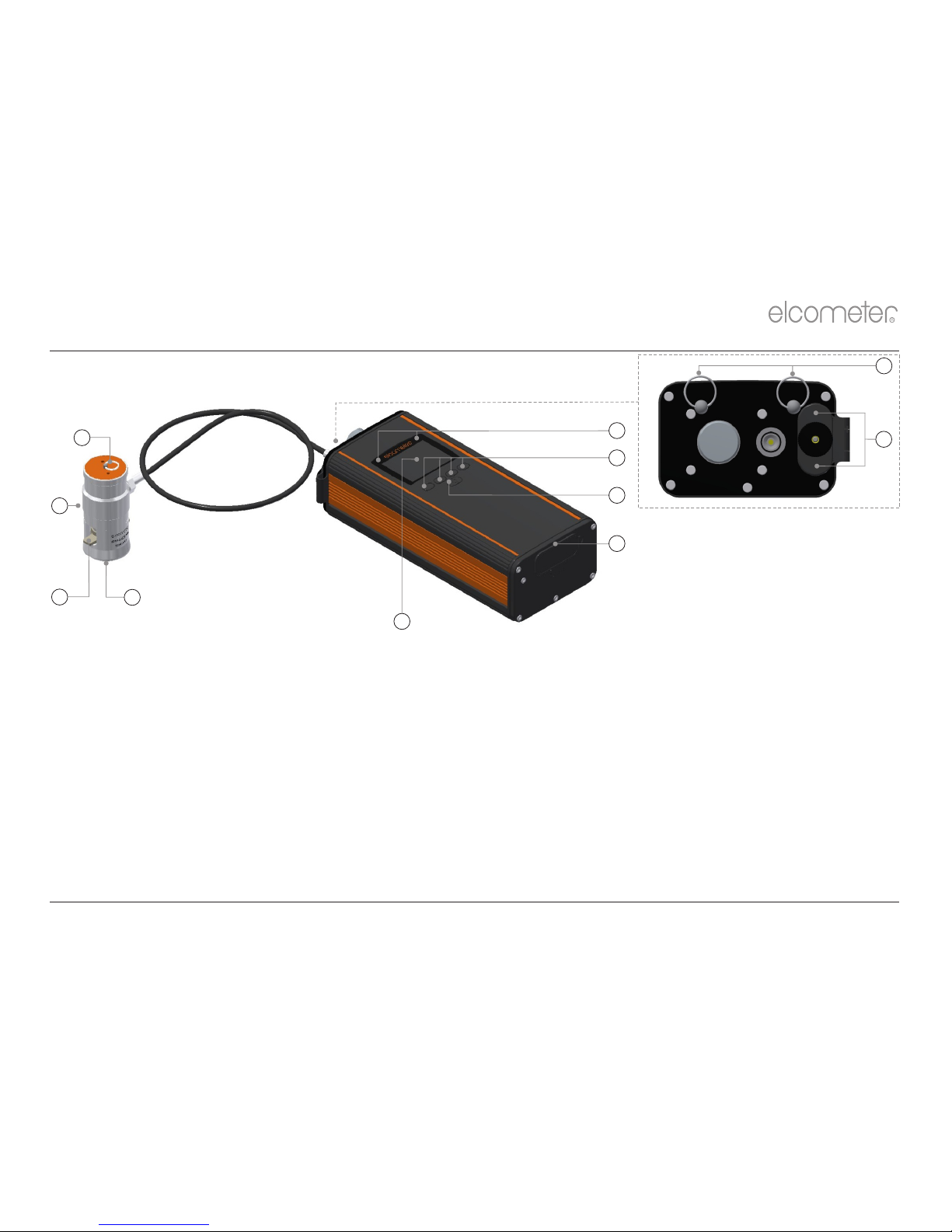
The Standard Actuator Skirt for 20mm dollies is illustrated above. Skirts for other dolly sizes and thin substrates are also available - see Section 14.3 - “Dolly Skirts” on
page 20 for details.
1 Actuator
2 Lanyard Ring
3 Shoulder Strap Connections
4 Battery Compartment
5 LED Indicators - Red (left), Green (right)
6 Multifunction Softkeys
2
1
3
4
5
6
7
8
7 On/Off Key
8 USB Data Output Socket (below cover)
9 LCD Display
a
10 Actuator Skirt
11 Quick Connect Coupling
9
10
11
<
Elcometer 510 Adhesion Tester
<
Actuator Lanyard
<
Standard Epoxy Adhesive (2x15ml tubes)
<
ElcoMaster™ 2.0 Software & USB Cable
<
Abrasive Pad
<
Carry Case
<
16 x AA Rechargeable Batteries
<
Calibration Certificate
<
8 Cell Battery Charger
<
User Guide
<
Shoulder Harness
Additional items in 20mm Kit:
Additional items in 50mm Kit:
<
20mm Dollies (x10)
<
50mm Dollies (x6)
<
20mm Dolly Standard Skirt
<
50mm Dolly Standard Skirt
<
20mm Dolly Cutter & Handle
<
50mm Dolly Cutter with Drill Arbor
2 BOX CONTENTS
www.elcometer.com3
en
R
3 USING THE GAUGE
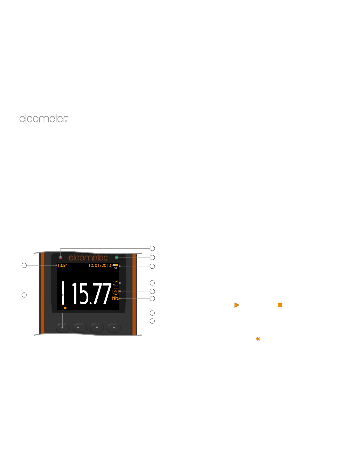
a
Red LED
b
Green LED
c
Power: Batteries (including battery life indicator &
number of pulls remaining)
d-2Pull Rate - MPa/s, psi/s, N/s, Nmm /s
e
Dolly Size - 10mm, 14.2mm, 20mm, 50mm
f
-2
Measurement Units - MPa, psi, Newtons, Nmm
g
b b
Start Test ( ) ; Stop Test ( ) ; Menu Softkey
h
Softkeys
i
Load Bar
j
Date & Time (when enabled and not in batching)
a
g
h
b
is displayed when the gauge is rewinding.
i
j
b
c
d
e
f
3 USING THE GAUGE (continued)
en
R
www.elcometer.com
4
k
Batching On
l
Last Reading (> [greater than] symbolizes ‘Did Not Fail’)
m
Actuator Load Value
n
User Selectable Statistics - 4 rows
o
Batch Name (when in batching)
p
Run Chart - last 20 readings (user selectable)
q
Power: USB
k
n
l
m
o
p
q
4 GETTING STARTED
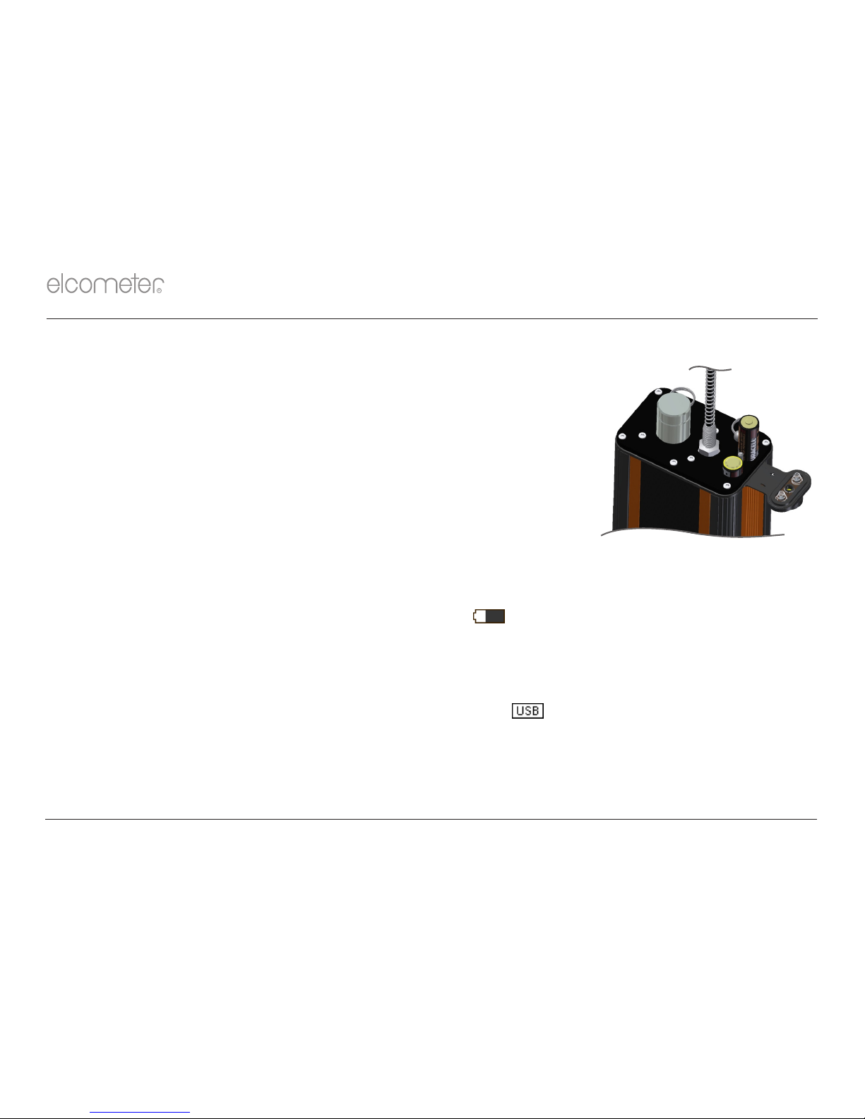
4.1 FITTING THE BATTERIES
Each gauge is supplied with 16 x AA NiMH rechargeable batteries and battery charger.
To insert or replace the batteries:
1 Unscrew the battery cap (turning anti-clockwise) and remove the
battery cover.
2 Insert 8 batteries taking care to ensure correct polarity.
3 Refit the cover and tighten the battery cap.
Each fully charged set of batteries last for approximately will
200 pulls up to 25MPa (3600psi) at 1MPa/s ( psi/s) using a 20mm dolly.145
The battery charger supplied can re-charge a set of 8 cells in approximately 5 hours. Care should be
taken to ensure the correct polarity when fitting the batteries into the charger.
The battery condition is indicated by the battery symbol at the top right of the display. When ( )
there is insufficient charge remaining to perform >100 tests, an indication of the approximate number
of tests remaining - based on pulls to 25MPa (3600psi), using a 20mm dolly - is also displayed below
the battery symbol.
The LCD display can be powered via USB. When connected, is displayed at the top right of the
display allowing various functions to be undertaken including batch setup, review and transfer of data
to PC or mobile device. Pull tests can not be performed using USB as it does not provide suf ficient
power to run the adhesion gauge motor.
en
R
www.elcometer.com5
-
+
+
-

4 GETTING STARTED (continued)
4.2 SELECTING YOUR LANGUAGE
1 Press and hold the ON/OFF button until the Elcometer logo is displayed.
é
2 Press Menu/Setup/Language and select your language using the softkeys.
ê
3 Follow the on screen menus.
To access the language menu when in a foreign language:
1 Switch the gauge OFF.
2 Press and hold the left softkey and switch the gauge ON.
é
3 Select your language using the softkeys.
ê
4.3 SETTING UP THE DISPLAY
A number of screen settings can be defined by the user via Menu/Setup/Screen Settings including:
Ÿ Screen Brightness; This can be set to ‘Manual’ or ‘Auto’ - the brightness is adjusted
automatically using the gauge’s ambient light sensor.
Ÿ Screen Timeout; The display will dim if inactive for more than 15 seconds and will go ‘black’ if
inactive for the period defined. Press any key, or tap the gauge to awaken it. The gauge will also
switch off automatically after 5 minutes of inactivity if ‘Gauge Auto Off’ is enabled via Menu/Setup.
Ÿ Screen Rotation; Using the internal accelerometer, the gauge rotates the display to allow the
user to easily read the pressure value at 0° or 180° orientation (‘Auto Display Rotation’).
en
R
www.elcometer.com
6

The colour LCD display is split into two halves; Top Display and Bottom Display. The user can define
what information is displayed in each half including:
Ÿ Selected Stats; As defined by the user via Display/Statistics/Select Statistics. The user can
choose to view only those selected or view all.
Ÿ Run Chart; A line trend graph of the last 20 measurements which is updated automatically after
each reading.
Ÿ Readings; The last reading is displayed under the current pressure reading and is only updated
when the current reading is saved.
To setup the display:
1 Press Display/Setup Display/Top Display (or Bottom Display as required).
é
2 Use the softkeys to highlight the required option and press ‘Select’.
ê
If ‘None’ is selected for one half and ‘Readings’ or ‘Run Chart’ for the other half, the readings or run
chart will fill the whole the screen. If any other combination of options is selected; the data will be
shown in the top or bottom display as specified.
4.4 SELECTING THE MEASUREMENT UNITS
-2
The Elcometer 510 Model S can display pull test results in MPa, psi, Newtons or Nmm . To select the
measurement units, press Menu/Setup/Units.
4.5 SELECTING THE DOLLY SIZE & PULL RATE
Prior to performing an adhesion test, the appropriate dolly size and pull rate must be selected. The
Elcometer 510 can be used with 10mm, 14.2mm, 20mm and 50mm dollies. As the pull rate is
determined by the dolly size, the dolly size must be selected first.
4 GETTING STARTED (continued)
en
R
www.elcometer.com7
4 GETTING STARTED (continued)
To set the dolly size and pull rate:
1 Press Menu/Dolly Size & Pull Rate.
é
2 Use the softkeys to highlight the required dolly size and press ‘Select’. The ‘Pull Rate’
ê
screen will now appear.
é
3 Use the softkeys to set the pull rate as required and press ‘Ok’ to set.
ê
en
R
www.elcometer.com
8
Dolly Size
Pre-defined Pull Rates
(Only the pull-rates listed below are available for selection)
MPa/s
psi/s
N/s
-2
Nmm /s
10mm
1.00, 2.00, 3.00, 4.00, 5.00
125, 200, 400, 600, 725
80, 160, 235, 315, 395
1.00, 2.00, 3.00, 4.00, 5.00
14.2mm
0.40, 0.70, 1.40, 2.00, 2.50
60, 100, 200, 300, 360
65, 110, 220, 315, 395
0.40, 0.70, 1.40, 2.00, 2.50
20mm
0.20, 0.30, 0.70, 1.00, 1.20
30, 50, 100, 150, 180
65, 95, 220, 315, 380
0.20, 0.30, 0.70, 1.00, 1.20
50mm
0.04, 0.08, 0.12, 0.16, 0.20
5, 8, 16, 24, 30
80, 160, 235, 315, 400
0.04, 0.08, 0.12, 0.16, 0.20
5 SECURING THE DOLLY
5.1 USING 10mm, 14.2mm OR 20mm DOLLIES
1 Prepare the surface of the dolly and the coating where the dolly is to be applied by roughening with
the abrasive pad. Then de-grease and clean both surfaces using a suitable solvent and allow to dry.
®
2 Mix equal quantities of the two part Araldite adhesive and apply a thin, even layer to the prepared
surface of the dolly.
4
®
Araldite adhesive is supplied by Elcometer however, other adhesives can be used - see Section 15
‘Adhesives’ on page 21.
3 Press the dolly firmly onto the prepared test surface and apply pressure to squeeze out excess
adhesive which should then be wiped clean.

en
R
www.elcometer.com9
4 Allow the adhesive to cure - see Section 15 ‘Adhesives’ on page 21.
If testing on vertical surfaces, you may wish to tape the dolly in place during cure.4
5 If required, score the coating around the dolly using the dolly cutter provided.
5.2 TESTING COATINGS ON CONCRETE USING 50mm DOLLIES
When testing coatings on concrete using 50mm dollies, scoring of the coating
down to, or into, the surface of the concrete may be required.
1 If testing on coatings thicker than 0.5 mm (20 mils) use the 50mm dolly cutter and
arbor (mounted in a drill press or hand drill) to cut a “ring” into the concrete.
Ensure that the scoring is perpendicular to the coating and that the test area is not 4
subjected to twisting or torque. To minimise heat and suppress dust, water lubrication
may be required.
2 Follow steps 1-4 in Section 5.1, making sure the dolly is positioned inside the cut
“ring”.
To score coatings thinner than 0.5 mm (20 mils), a sharp knife may be sufficient to carefully score around
the dolly once it has been secured in place by adhesive.
5 SECURING THE DOLLY (continued)
Concrete Substrate
6 ATTACHING THE GAUGE TO THE DOLLY
c
1 Pull up the quick connect coupling, place the actuator (with skirt fitted ) over the
dolly then release the coupling to grip the dolly.
4 The quick connect coupling is not a bayonet fitting. Do not attempt to push the actuator on to
the dolly without lifting the quick connect coupling.
c
Skirts for 10mm, 14.2mm, 20mm and 50mm dollies and thin substrates are available - see Se etails.ction 14.3 ‘Dolly Skirts’ on page 20 for d
en
R
www.elcometer.com
10
6 ATTACHING THE GAUGE TO THE DOLLY (continued)
When testing at height or on vertical surfaces, in order to prevent damage to the surrounding coating or harm to
the user, it may be necessary to use the Magnetic Anchor Clamp accessory, part number T99923797. This
connects to the lanyard ring on the top of the actuator to prevent the actuator from falling when the dolly is pulled
from the substrate.
1 Press and hold the ON/OFF button to switch the gauge on.
2 Ensure that the measurement units, dolly size and pull rate are set as required, see section 4.
3 Press the start softkey (4) to begin the test. Load is applied at the rate defined, displayed
numerically on the screen and illustrated on the load bar.
4 The load continues to increase at the defined rate until either:
a) the dolly pulls off;
b) the gauge maximum pull load / pressure has been reached (eg. 25MPa for a 20mm dolly)
At this point, the gauge re-winds to ‘zero’ and the user is asked if they wish to save the reading.
4 ‘---’ indicates a reading outside of range
4 If the maximum pull load / pressure has been reached, the gauge will not re-wind to ‘zero’ until the default
hold time of 0.5 seconds has elapsed.
4 The gauge re-winds to ‘zero’ at a set rate of 1.5MPa/s or equivalent.
5 Pull up the quick connect coupling to release the dolly and assess the results, see Section 8.
The stop softkey (<) can be pressed at any time during the test. If pressed, the user is asked if they
wish to save the reading and the gauge re-winds to ‘zero’. If saved, the “stopped” reading is included
in the statistics.
Dollies can be reused after cleaning until either the top of the dolly (where it is held in position by the
quick connect coupling) is severely deformed or the dolly surface is no longer flat. Additional dollies
are available from Elcometer or your local supplier - see Section 14.1 - ‘Dollies’ on page 18 for
details.
7 PERFORMING THE TEST

8.1 EXAMINING THE DOLLY
a) Cohesive Failure: The coating fails within the body of a
coating layer leaving the same coating on the surface and on
the dolly face.
b) Adhesive failure: Is a failure at the interface between layers
(intercoat) where one pulls away from the other. The
“coating” on the dolly face will not be the same as that on the
test area.
c) Glue failure: When no coating is present on the dolly it must be
recorded as a failure of the glue. This is normally due to
incorrect or insufficient mixing of the component parts of the
adhesive, incompatibility between the adhesive, the coating,
the dolly, and / or the test surface - see Section 5 - ‘Securing
the Dolly’ on page 8 for more information.
8 ASSESSING THE RESULTS
en
R
www.elcometer.com11
Dolly Face
Substrate
a) 100% Cohesive Failure
b) 100% Adhesive Failure Between Two
Layers
c) Glue Failure
Layer 2
Substrate
Glue
Dolly Face
Key
Layer 1
Layer 3
Many National and International Standards including ISO 4624 & ASTM D4541, require the user to
record not only the pull-off force but also the nature of the fracture by examining the bottom of the dolly
and assessing the adhesive / cohesive failure.

en
R
www.elcometer.com
12
8 ASSESSING THE RESULTS (continued)
8.2 EXAMINING THE DOLLY (COATINGS ON CONCRETE)
When testing coatings on concrete it is common for the adhesive bond
between the coating and the concrete to exceed the strength of the
concrete itself. In this case concrete will be removed from the surface
and will be seen on the coating on the dolly face.
Observing the test area will give additional information about the type of
failure; adhesion and cohesion between different layers of the coating.
Adhesive
Failure
Partial Coating
Failure
Concrete
Failure
Coating
Failure
9 BATCHING
9.1 BATCH FUNCTIONS
The Elcometer 510 Model S gauge can store up to 60 readings in one batch and has the following
batching functions:
Ÿ Batch/New Batch; Create a new batch - see Section 9.2 for further information.
Ÿ Batch/Open Existing Batch; Open an existing batch.
Ÿ Batch/Edit Batch/Clear Batch; Clear all readings within the batch - but leaving all batch header
information.
Ÿ Batch/Review Batch; Review the readings, statistics and batch information - see Section 10 for
further information.
Ÿ Batch/Edit Batch/Delete Batch; Delete the batch entirely from the gauge.

en
R
www.elcometer.com13
9 BATCHING (continued)
Ÿ Batch/Deleted Reading/Delete without Tag; Delete the last reading entirely.
Ÿ Batch/Deleted Reading/Delete with Tag; Delete the last reading but mark it as deleted in the
batch memory.
9.2 CREATING A NEW BATCH
Many Standards require the user to record not only the pull-off force and the nature of the fracture but
also details of the test equipment used; if a support ring was used and its dimensions, if, and by what
means, the coating was cut around the dolly.
This additional information is recorded within the batch header and can be transferred to PC to be
included on any report within ElcoMaster. For further information on ElcoMaster™ 2.0, visit
www.elcometer.com.
To create a new batch select Batch/New Batch and add the following criteria as required:
Ÿ Dolly Size & Pull Rate; (Batch/New Batch/Dolly Size & Pull Rate)
Ÿ Cutting Device; the type of cutting device used, if any, to score the coating around the dolly;
(Batch/New Batch/Cutting Device)
Ÿ The dolly skirt type; (Batch/New Batch/Skirt Type)
- Select ‘20mm Standard’ for Standard Skirt for 10, 14.2 and 20mm dollies;
- Select ‘50mm Standard’ for Standard Skirt for 50mm dollies;
- Select ‘14.2mm Thin Substrate’ for Thin Substrate Skirt for 14.2mm dollies;
- Select ‘20mm Thin Substrate’ for Thin Substrate Skirt for 20mm dollies;
Note: A new batch can not be created if a batch already exists. The existing batch must be deleted first.

en
R
www.elcometer.com
14
9 BATCHING (continued)
Note: The Elcometer 510 dolly skirt has an integrated support ring, therefore
identifying the dolly skirt used records the use of a support / bearing ring as
required by some standards, together with the support ring dimensions - see
Section 14.3 ‘Dolly Skirts’ on page 20 for dimensions.
These details can be added and amended until the first reading has
been stored in the batch after which no changes can be made.
This information is saved in the batch header and can be viewed at any
time via Batch/Review Batch/Batch Information.
Batch Information
Batch 1
Created
Date Last Verified
Time Last Verified
Pull Rate
Dolly Size
Cutting Device
Skirt Type
Back
15:31
28/11/2013
25/11/2013
12:49
1.00 MPa/s
20 mm
Dolly Cutter
20 STD
é
é
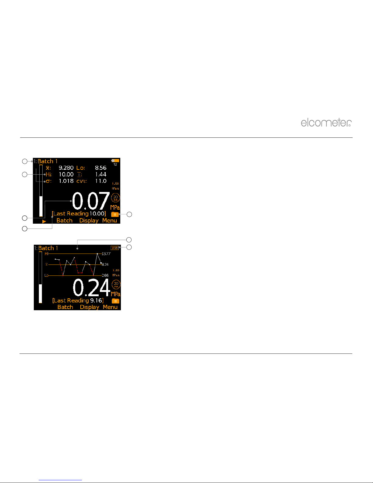
10.1 BATCH STATISTICS (Batch/Review Batch/Statistics)
Displays statistical information for the batch including:
Ÿ Number of readings in the batch ( )
Ÿ Average reading for the batch ( )
Ÿ Lowest reading in the batch ( )
Ÿ Highest reading in the batch ( )
Ÿ Range ( ); the difference between the highest and lowest reading
in the batch
Ÿ Standard Deviation ( )
Ÿ Coefficient of Variation ( )
10 REVIEWING BATCH DATA
Statistics
Batch 1
Back Zoom+
6
4.01
5.99
32.9
7.592
10.00
2.498

en
R
www.elcometer.com
15
Note: The calculation of standard deviation is based on the distribution of individual fracture strength values being
normal, that is forming a normal curve when plotted as a frequency chart. If adhesion values for pulls that are not
completed are included in the calculation, i.e. pulled to a limit value or maximum and not to fracture, the
distribution will not be normal and the standard deviation calculation will not be mathematically correct. For the
purpose of assessing the distribution of values in this case, however, the calculation will be included as though all
the dollies were pulled to coating failure and it should be noted that the resulting calculation is for guidance only .
10.2 BATCH READINGS (Batch/Review Batch/Readings)
Displays all measurement data for each individual reading within the batch including:
Ÿ The reading value;
Ÿ Date and time stamp for each test;
Ÿ Test duration.
Note: The test duration includes the hold time but does not include the time it takes for the gauge to re-wind to ‘zero’.
é
Press the softkeys to scroll through the readings and è to move to the next information screen.
ê
10 REVIEWING BATCH DATA (continued)
Readings
Batch 1
1
2
3
4
5
6
Back
10.02 MPa
5.17 MPa
7.86 MPa
4.01 MPa
8.51 MPa
10.00 MPa
é
é
é
Readings
Batch 1
1
2
3
4
5
6
Back
14:00:39
14:01:06
14:02:05
14:03:57
14:06:33
14:08:41
10/01/14
10/01/14
10/01/14
10/01/14
10/01/14
10/01/14
é
é
é
Readings
Batch 1
1
2
3
4
5
6
Back
31.25 Seconds (s)
31.42 Seconds (s)
30.90 Seconds (s)
32.14 Seconds (s)
31.83 Seconds (s)
31.19 Seconds (s)
é
é
é
15
en
R
www.elcometer.com
16
The Elcometer 510 is factory calibrated. The calibration of the gauge can be verified in
the field using the Elcometer Adhesion Verification Unit (AVU), part number
T99923924C and the Elcometer 510 Verify Calibration wizard, Menu/Verify Calibration.
To verify the calibration:
é
1 Select Menu/Verify Calibration and use the softkeys to highlight the
ê
required the dolly size; 20mm or 50mm. Press ‘Ok’ to select.
2 Switch on the Elcometer AVU and ensure that the appropriate dolly
adaptor is fitted and the measurement units are the same as the
Elcometer 510 (refer to the instructions supplied with the Elcometer AVU).
3 Connect the Elcometer 510 actuator (with skirt fitted) to the Elcometer
AVU dolly adaptor.
4 Press ‘Ok’ on the Elcometer 510 when connected. The Elcometer 510
automatically starts to apply pressure until the first test load is reached.
5 Compare the test load with the reading on the Elcometer AVU display. If the
Elcometer AVU reading is within the acceptable range, displayed in brackets
underneath the test load, press ‘Ok’ to proceed to the next test pressure and
repeat step 4. (If outside the acceptable range, re-calibration is
recommended. Press ‘Escape’ to exit the calibration verification procedure
and contact Elcometer or your local supplier for further information).
6 , if it When the final test load has been reached is within the acceptable range, press ‘Verify’ to update
the gauge or ‘Escape’ to cancel. The date and time of the last verification procedure is recorded against
each batch and can be viewed via Batch/Review Batch/Batch Information.
Note: The acceptable range is based on the ‘system’ accuracy - the accuracy of the Elcometer 510 and Elcometer AVU
unit combined. Measurement verification points: 20mm Dolly; 5, 15 & 25MPa, 50mm Dolly; 0.8, 2.4 & 4.0MPa (or
equivalent units)
11 VERIFYING THE GAUGE CALIBRATION
Verify Calibration
5.00 MPa
(4.72 - 5.28 MPa)
Press Escape To Cancel
Ok To Continue
Escape Ok
en
R
www.elcometer.com17
12 MENU STRUCTURE
Menu
Delete Last Reading
Dolly Size / Pull Rate
Setup
Verify Calibration
About
Reset
Emergency Light
Setup
Language
Time and Date
Beep Volume
Screen Settings
Units
Gauge Auto Off
Time and Date
Set Time
Set Date
Set Format
Display Time and Date
○
Screen Settings
Screen Brightness
Screen Timeout
Opening Screen
Screen Rotation
○
○
Units
MPa
psi
Newtons
2
N/mm
○
○
○
○
○
About
Gauge Information
Contact
Legal
Legal
Legal Notices
Regulatory
Display
Setup Display
Statistics
Setup Display
Top Display
Bottom Display
Top Display
None
Selected Stats
Run Chart
Readings
○
○
○
○
Statistics
Clear Statistics
View Selected
View All
Select Statistics
○
○
○
Select Statistics
Number of Readings
Mean
Lowest Reading
Highest Reading
Range
Standard Deviation
Coefficient of Variation
○
○
○
○
○
○
○
Batch
Memory Free xx.x%
New Batch
Open Existing Batch
Exit Batching
Edit Batch
Review Batch
Deleted Reading
New Batch
Open Batch n
Dolly Size & Pull Rate
Cutting Device
Skirt Type
Dolly Size
10 mm
14.2 mm
20 mm
50 mm
○
○
○
○
Cutting Device
None
Dolly Cutter
Knife
○
○
○
Skirt Type
Standard 20 mm
Standard 50 mm
Thin Substrate 14.2 mm
Thin Substrate 20 mm
○
○
○
○
Edit Batch
Clear Batch
Delete Batch
Review Batch
Statistics
Batch Information
Readings
Deleted Reading
Delete With Tag
Delete Without Tag
○
○
Dolly Size
10 mm
14.2 mm
20 mm
50 mm
○
○
○
○
Pull Rate
x.xx
MPa/s
Regulatory
xxxxx
xxxxx
xxxxx
Bottom Display
None
Selected Stats
Run Chart
Readings
○
○
○
○

R
www.elcometer.com
18
en
13.1 DOWNLOADING DATA USING ELCOMASTER™ 2.0
Using ElcoMaster™ 2.0 - supplied with each gauge, and available as a free download at
elcometer.com - gauges can transmit readings via USB to a PC for archiving and report generation.
For more information on ElcoMaster™ 2.0 visit www.elcometer.com
13.2 UPGRADING YOUR GAUGE
Gauge firmware can be upgraded to the latest version by the User via ElcoMaster™ 2.0, as they
™
become available. ElcoMaster 2.0 will inform the User of any updates when the gauge is connected
to the PC with an internet connection.
13 DOWNLOADING DATA & UPGRADING YOUR GAUGE
14 SPARES & ACCESSORIES
14.1 DOLLIES
The Elcometer 510 can be used with a range of dollies, also referred to as test elements or stubs.
d
10, 14.2, 20 and 50mm diameter dollies are available to purchase as an optional accessory .
10mm: ideal for testing up to 100MPa (14400psi) on very small surface areas.
14.2mm: ideal for testing on small surface areas, for measurements over 25MPa (3600psi) and
suitable for use on some curved surfaces.
20mm: suitable for use on a variety of coatings / substrates.
50mm: Coatings on concrete, cementitious layers and uneven surfaces can be tested more
effectively with the larger 50mm dolly. Our 50mm dollies are also available in stainless
steel as required for testing in accordance with DIN 1048 part 2 and BS EN 12636.
d
Please ensure the appropriate dolly skirt is fitted. See Section 6 - ‘Attaching the Gauge to the Dolly’ and Section 14.3 - ‘Dolly Skirts’ on pages 9 and 20 for
further information.

en
R
www.elcometer.com19
14 SPARES & ACCESSORIES (continued)
Description Sales Part Number
Aluminium Dolly 10mm (x10) T5100010AL-10
Aluminium Dolly 10mm (x100) T5100010AL-100
Aluminium Dolly 14.2mm (x10) T9990014AL-10
Aluminium Dolly 14.2mm (x100) T9990014AL-100
Aluminium Dolly 20mm (x10) T9990020AL-10
Aluminium Dolly 20mm (x100) T9990020AL-100
Aluminium Dolly 50mm (x4) T9990050AL-4
Stainless Steel Dolly 50mm (x4) T9990050SS-4
14.2 DOLLY CUTTERS
Standards or test methods will determine if the Inspector should cut / score around the dolly prior to
test to separate the test area from the rest of the coating; information which should be recorded with
the results.
The Elcometer 510 is supplied with a dolly cutter and handle appropriate for the dolly size included in
the kit. Spare / replacement cutters are available to purchase using the sales part numbers below.
Description For Dolly Sizes (mm) Sales Part Number
Dolly Cutter 14.2mm T9990014CT
Dolly Cutter 20mm T9990020CT
Dolly Cutter 50mm T9990050CT
Dolly cutter handles must be ordered separately - a handle is not supplied with the dolly cutter
accessory.
R
www.elcometer.com
20
en
Description For Dolly Cutter Sales Part Number
Dolly Cutter Handle T9990014CT / T9990020CT T9991420H
Dolly Cutter Arbor T9990050CT T9990050H
14.3 DOLLY SKIRTS
Standard skirts are available for 10mm, 14.2mm and 20mm dollies as well as 50mm dollies. Special
skirts are also available for testing on thin substrate to even out the load, as using a standard skirt on a
thin substrate may cause the substrate to bend or flex during test.
14 SPARES & ACCESSORIES (continued)
Description For Dolly Sizes (mm) Integrated Support Sales Part Number
Ring Dimensions
† ‡
I/D O/D
Standard Skirt 10mm, 14.2mm & 20mm 30mm 40.4mm T999101420S
Thin Substrate Skirt 14.2mm T9990014T16.3mm 40.4mm
Thin Substrate Skirt 20mm T9990020T21mm 40.4mm
Standard Skirt 50mm T9990050S52mm 72mm
14.4 MAGNETIC ANCHOR CLAMP
Ideal when testing at height or on vertical surfaces to prevent damage to
the surrounding coating or harm to the user, the magnetic anchor clamp
connects to the lanyard ring on the top of the actuator to prevent the
actuator from falling when the dolly is pulled from the substrate.
Description Sales Part Number
Magnetic Anchor Clamp Accessory T99923797
† ‡
I/D: Inner Diameter O/D: Outer Diameter

en
R
www.elcometer.com21
15 ADHESIVES
The adhesive supplied with the Elcometer 510 is Araldite Standard, a two-pack epoxy paste which is
®
mixed from approximately equal volumes of the two components. Measurement by eye is sufficient.
When mixed it should be used within one hour. Curing Times: 24 hours at 25°C (77°F);
3 hours at 60°C (140°F)
Araldite is suitable for warm and hot environments. Lower temperatures can require extended curing
®
times of up to 3 days or more. The expiry date of the adhesive should be checked before use.
Adhesive which has expired should not be used.
Unused adhesive must be disposed of as special waste unless it has been fully cured. To dispose of
excess adhesive at the end of its shelf life simply mix the remaining material and allow it to cure before
disposal.
Description Sales Part Number
Araldite Standard Two Part Epoxy Adhesive; 2x15ml Tubes T99912906
®
A Material Safety Data Sheet for adhesive supplied by Elcometer can be downloaded via our website:
Araldite Standard Two Part Epoxy Adhesive: www.elcometer.com/images/MSDS/araldite_epoxy_adhesive.pdf
®
Note: Other suitable adhesives include Loctite Hysol 907 and 3M™ Scotch-Weld™ Epoxy Adhesive.
® ®
The suitability of any adhesive should be determined by the user. Some coatings can be adversely affected by
adhesives. Some adhesives can be contaminated by coating environments, solvents etc.

en
R
www.elcometer.com
22
Dolly Diameter
10mm
14.2mm
20mm
50mm
Operating Range
8 - 100MPa
(1200 - 14400psi)
4 - 50MPa
(600 - 7200psi)
2 - 25MPa
(300 - 3600psi)
0.3 - 4.0MPa
(50 - 580psi)
Operating Temperature
Range
-10 to 50°C (14 to 122°F); Humidity: 0 - 95% RH
Pressure Rating
26MPa (3800psi)
Pressure Resolution
0.01MPa (1psi)
Pressure Accuracy
±1% of full scale
Pull Rate Range
1.0 - 5.0MPa/s
(125 - 725psi/s)
0.4 - 2.5MPa/s
(60 - 360psi/s)
0.2 - 1.2MPa/s
(30 - 180psi/s)
0.04 - 0.20MPa/s
(5 - 30psi/s)
Pull Rate Setting
Resolution
0.1MPa/s
(1psi/s)
0.1MPa/s
(1psi/s)
0.1MPa/s
(1psi/s)
0.01MPa/s
(0.1psi/s)
Pull Rate Display
Resolution
0.01MPa (1psi)
Pull Rate Accuracy
± (2.5% + 0.3 seconds) over time of test
16 TECHNICAL SPECIFICATION

en
R
www.elcometer.com23
Dolly Diameter
10mm
14.2mm
20mm
50mm
Gauge Memory
Up to 60 readings in one batch
Power Supply
e
8 x AA NiMH batteries
Battery Life
200 pulls per charge up to 25MPa (3600psi) at 1MPa/s (150psi/s)
Instrument Weight
2.9kg (6.4lb)
2.9kg (6.4lb)
2.9kg (6.4lb)
3.1kg (8.3lb)
Kit Weight
n/a
n/a
6.1kg (13.5lb)
7.3kg (16.1lb)
Instrument Length
260mm (10.3")
Actuator Height
85mm (3.4")
(10mm skirt fitted)
85mm (3.4")
(14.2mm skirt fitted)
85mm (3.4")
(20mm skirt fitted)
110mm (4.3")
(50mm skirt fitted)
Can be used in accordance with:
ASTM C1583, ASTM D4541, ASTM D7234-12, AS/NZS 1580.408.5, BS 1881-207, DIN 1048-2, EN 1015-12,
EN 12636, EN 13144, EN 1348, EN 1542, EN 24624, ISO 16276-1, ISO 4624, NF T30-606, NF T30-062
16 TECHNICAL SPECIFICATION (continued)
e
The numbe r of pulls rema ining with a ba ttery charge is calculated using the NiHM batteries supplied. Alternative AA batteries (alkaline for example), can be
used but will affect battery performance and the accuracy of the “pulls remaining” indication.

en
R
www.elcometer.com
24
This product meets the Electromagnetic Compatibility Directive
The product is Class B, Group 1 ISM equipment according to CISPR 11
Group 1 ISM product: A product in which there is intentionally generated and/or used conductively coupled radio-frequency energy which is necessary for the internal
functioning of the equipment itself.
Class B product are suitable for use in domestic establishments and in establishments directly connected to a low voltage power supply network which supplies buildings
used for domestic purposes.
The USB is for data transfer only and is not to be connected to the mains via a USB mains adapter.
The ACMA compliance mark can be accessed via: Menu/About/Legal/Regulatory
This device complies with Part 15 of the FCC Rules. Operation is subject to the following two conditions: (1) this device may not cause harmful interference, and (2) this
device must accept any interference received, including interference that may cause undesired operation.
NOTE: This equipment has been tested and found to comply with the limits for a Class B digital device, pursuant to Part 15 of the FCC Rules. These limits are designed
to provide reasonable protection against harmful interference in a residential installation. This equipment generates, uses and can radiate radio frequency energy and, if
not installed and used in accordance with the instructions, may cause harmful interference to radio communications. However, there is no guarantee that interference will
not occur in a particular installation. If this equipment does cause harmful interference to radio or television reception, which can be determined by turning the equipment
off and on, the user is encouraged to try to correct the interference by one or more of the following measures:
-- Reorient or relocate the receiving antenna.
-- Increase the separation between the equipment and receiver.
-- Connect the equipment into an outlet on a circuit different from that to which the receiver is connected
-- Consult the dealer or an experienced radio/TV technician for help.
Modifications not expressly approved by Elcometer Limited could void the user's authority to operate the equipment under FCC rules.
This Class B digital apparatus complies with Canadian ICES-003.
is a registered trademark of Elcometer Limited, Edge Lane, Manchester, M43 6BU. United Kingdom
All other trademarks acknowledged.
R
17 LEGAL NOTICES & REGULATORY INFORMATION

en
R
www.elcometer.com25
 Loading...