

Page 1

R
User Guide
Elcometer 224
Surface Profile Gauge
www.elcometer.com
Page 2
Section
Page
1
Gauge Overview
en-2
2
Box Contents
en-2
3
Using the Gauge
en-3
4
Getting Started
en-4
5
Taking a Reading
en-6
6
Calibrating & Testing the Gauge Calibration
en-7
7
Batching - Model T
en-9
8
Displaying Graphs
en-9
9
Menu Structure - Model B
en-10
10
Menu Structure - Model T
en-11
11
Downloading Data & Upgrading Your Gauge
en-12
12
Technical Specification
en-13
13
Elcometer 224 Separate Probes
en-13
14
Legal Notices & Regulatory Information
en-14
CONTENTS
R
Pb
These operation instructions are a short User Guide only. A copy of both this Instruction Manual and an English
language extended version are available for download on our website elcometer.com. For the avoidance of doubt,
please refer to the original English language version.
Gauge Dimensions: Integral: 168 x 73 x 37mm (6.61 x 2.87 x 1.46")
Separate: 141 x 73 x 37mm (5.55 x 2.87 x 1.46")
Gauge Weight: Integral: 218g (7.69oz) including batteries
Separate: 161g (5.68oz) including batteries
Applicable Patents: GB2505193, US9261345
© Elcometer Limited 2012 - 201 . All rights reserved. No part of this document may be reproduced, transmitted, 9
transcribed, stored (in a retrieval system or otherwise) or translated into any language, in any form or by any
means (electronic, mechanical, magnetic, optical, manual or otherwise) without the prior written permission of
Elcometer Limited.
en-1
Hg
www.elcometer.com
Page 3
1 GAUGE OVERVIEW
<
Elcometer 224 Surface Profile Gauge
<
Calibration Test Foils; Nominal Values 125 & 500µm and
a
Glass Zero Tile (Integral gauges)
<
a
Probe Protection Cap (Integral gauges)
<
Wrist Harness
<
Protective Case (Model B)
<
Transit Case (Model T)
<
1 x Screen Protector
<
2 x AA Batteries
<
®
USB Cable & ElcoMaster Software (Model T)
<
Test Certificate
<
User Guide
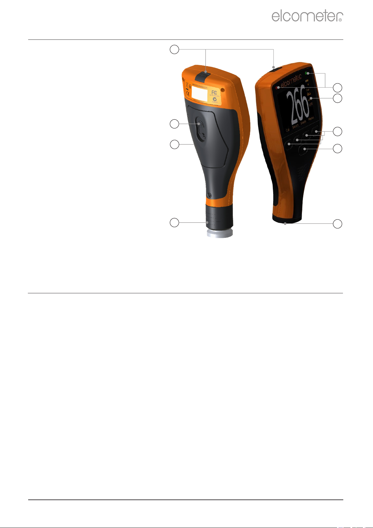
1 LED Indicators -
Red (left), Green (right)
R
9
2 Colour Screen
3 Multifunction Softkeys
4 On/Off Key
5 Separate Probe
Connection
6 Internal Probe
7 Wrist Strap Connection
8 Battery Compartment
(¼ turn open/close)
9 USB Data Output Socket
(below cover)
1
2
8
3
7
6
4
5
2 BOX CONTENTS
a
For separate gauges, the test foils, glass zero tile and probe protection cap are supplied with the
separate probe.
www.elcometer.com
en-2
Page 4
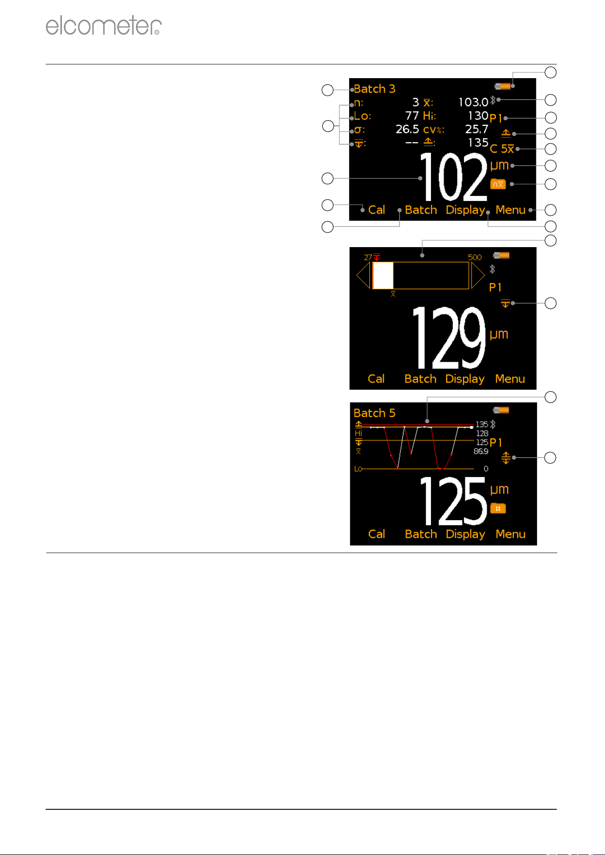
Model
a
Battery Life Indicator
BT
b
Bluetooth On - Grey: not
connected; Orange: connected
T
c
Probe Scale
BT
d
Upper Limit On
T
e
#
Measurement Mode
BT
f
Units of Measurement -
µm, mils, mm, inch
BT
g
Batch Type -
normal, counted average
T
h
Menu Softkey
BT
i
Display Softkey
BT
j
Batch Softkey
BT
k
Calibration Softkey
BT
l
Reading Value
BT
m
User Selectable Statistics -
4 rows
BT
n
Batch Name (when in Batching)
T
o
Bar Graph - highest, lowest &
average reading
BT
p
Lower Limit On
T
p
Run Chart - last 20 readings
TrUpper & Lower Limits On
T
R
3 USING THE GAUGE
a
n
b
m
l
c
d
e
f
g
k
j
h
i
o
p
q
r
4 GETTING STARTED
4.1 ENSURING YOUR GAUGE HAS THE LATEST FIRMWARE &
UPGRADING YOUR GAUGE
To ensure that your gauge has the most up-to-date gauge firmware,
allowing you to benefit from the latest features and functionality, we
recommend that the gauge is connected to ElcoMaster on a regular
basis and before first use.
Simply connect the gauge via USB to an internet connected computer
running ElcoMaster using the ‘Connect Gauge’ feature. If a later
version of the gauge firmware is available, ‘Update Gauge’ will be
displayed to the right of the gauge details. Click ‘Update Gauge’ to
install the latest firmware.
#
The icon displayed depends on the measurement mode selected. If ‘Immediate’ mode is selected, no
icon is displayed. See Section 4.4 ‘Selecting the Measurement Mode’ on page en-4 for further
information.
en-3
®
®
www.elcometer.com
Page 5
4 GETTING STARTED (continued)
Icon Displayed
Measurement Mode
None
continued...
Immediate: Allows the users to take single measurements
which are displayed on the gauge (Model B & T) and saved
into the batch memory (Model T only).
Note: This mode allows gauges to be used and measurements to be taken
in the same way as older Elcometer 224 models.
4.2 SELECTING YOUR LANGUAGE
1 Press and hold the / button until the Elcometer logo is ON OFF
displayed.
2 Select your language using the softkeys.
é
ê
3 Follow the on screen menus.
To access the language menu when in a foreign language:
1 Switch the gauge .OFF
2 Press and hold the left softkey and switch the gauge .ON
3 Select your language using the softkeys.
é
ê
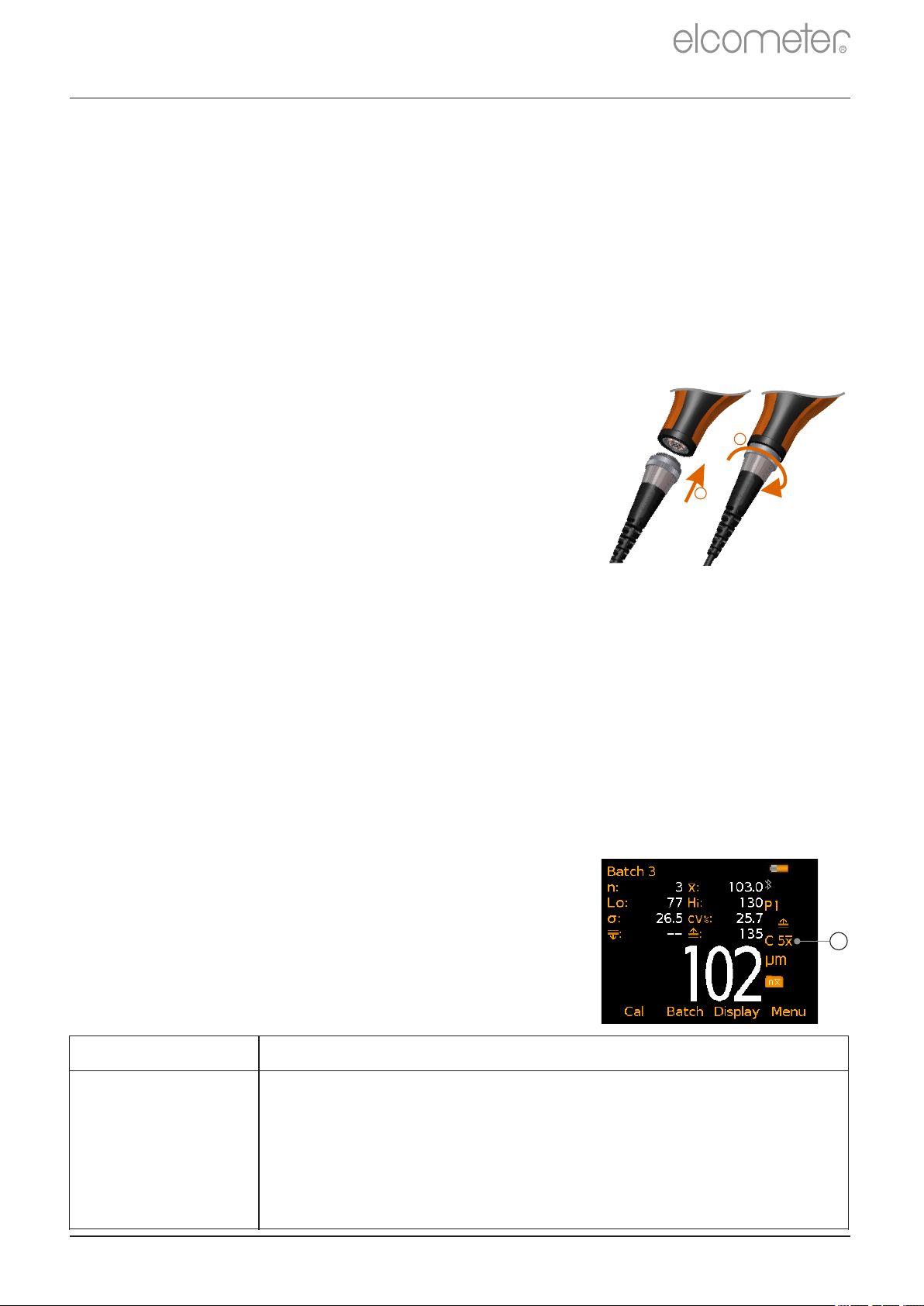
4.3 CONNECTING THE PROBE -
R
SEPARATE GAUGES ONLY
1 Rotate the probe plug to align the pins.
2
2 Screw in the collar - clockwise.
1
See Section 13 ‘ Elcometer 224 Separate Probes’
on page en-13 for details of the probes available.
4.4 SELECTING THE MEASUREMENT MODE
The Elcometer 224 has a choice of three measurement modes;
‘Immediate’, ‘Custom’ and ‘Standards’ - see the table below for an
explanation of the different modes available. The mode selected
depends on which International Standard the user is working in
accordance with.
To select the measurement mode:
1 Press Menu/Setup/Measurement Mode or when in batching
(Model T only), Batch/New Batch/Measurement Mode.
2 Use the softkeys to select the required measurement mode.
é
ê
The measurement mode selected and in use, is
indicated by the icon shown on the right of the
display (a). If no icon is displayed, ‘Immediate’
Mode is in use.
www.elcometer.com
a
en-4
Page 6

R
Icon Displayed
Measurement Mode
C 5x, C 10x
C 5H, C 10H
C 5L, C 10L
Custom: The user can choose to take either 5 or 10
readings and can choose to display on the gauge
(Model B & T) and save into the batch memory (Model T
only), the mean/average, highest or lowest measurement
of each set of readings.
Standards:
Select from AS 3894.5, ASTM 4417-B or SANS 5772
AS
AS 3894.5 (Australian Standard):
The user is prompted to take 10 readings. The lowest 5 readings are
discarded and the mean/average measurement of the remaining 5
readings is displayed on the gauge (Model B & T) and saved into the
batch memory (Model T only).
ASTM x
ASTM H
ASTM 4417-B (American Society for Testing & Materials):
The user is prompted to take 10 readings and can choose to display
on the gauge (Model B & T) and save into the batch memory
(Model T only), the mean/average or highest measurement of each
set of 10 readings.
SANS
SANS 5772 (South African National Standard):
The user is prompted to take 5 readings and the mean/average
measurement of each set of 5 readings is displayed on the gauge
(Model B & T) and saved into the batch memory (Model T only).
Note: When using ‘Custom’ or ‘Standards’ mode, only the mean/average, highest or lowest
measurement as specified for each set of 5 or 10 readings is saved in the batch
memory. The individual readings are not stored. This also applies when using ‘Live
®
Readings’ mode in ElcoMaster to transmit readings from a gauge to a PC to be
®
stored in a batch within ElcoMaster .
4 GETTING STARTED (continued)
When ‘Custom’ or ‘Standards’ measurement mode is selected:
4 The circles indicate the number of readings
out of the set of predefined readings which
a
are to be taken (a). In this example, 3 out of
the 10 readings have been taken.
4 The value of the last reading taken is
b
displayed on screen in grey, below the
reading circles (b).
4 When the last of the predefined number of
readings has been taken, the
c
mean/average, highest or lowest
measurement (as selected by the user) is
en-5
displayed (c).
www.elcometer.com
Page 7

ü
DO
•
Hold the probe by the probe sleeve.
•
Firmly place the probe onto the surface
•
Allow the sleeve to make contact with the surface - to improve
accuracy.
û
DO NOT
•
Drag the probe over the surface
•
Bang the probe down hard onto the surface
•
Swing the probe by its cable
5 TAKING A READING
1 Hold the probe by its sleeve
2 To take a reading, bring the probe down onto the surface whilst
holding it perpendicular
3 For subsequent readings, lift the probe off and then replace it
onto the surface
R
4 To accurately assess the surface profile 5-10 readings should be
taken over a surface area of 150mm (6 sq. in.). The average of
2
these readings will indicate the surface profile peak-to-valley
height of that area.
4 When using ‘Immediate’ mode, users can pre-define the number of readings
using the counted average function. When in batching (Model T), press
Batch/New Batch/Batch Type, select “Counted Average” and set the number of
readings as required. The average of this pre-defined number will be saved into
the batch, but the individual readings within the counted average are not saved.
When not in batching (Model B & T), press Display/Statistics/Counted Average
and set the number of readings as required. When using counted average, the
gauge switches between displaying statistics based on individual readings to
statistics based on the counted average, as each set of reading are taken.
4 The display will dim if inactive for more than 15 seconds and will go ‘black’ if
inactive for the period defined in Menu/Setup/Screen Settings/Screen Timeout.
Press any key or tap the gauge to awaken it.
4 The gauge will switch off automatically after 5 minutes of inactivity.
4 - - - indicates reading outside range of probe.
www.elcometer.com
en-6
Page 8

R
6 CALIBRATING AND TESTING THE GAUGE CALIBRATION
6.1 CALIBRATING THE GAUGE
Adjusting the calibration of the gauge is the process of zeroing the
gauge on a smooth glass zero tile. Calibration foils can be used to
check the accuracy of the gauge across its measurement range.
The Elcometer 224 Model T has a choice of calibration methods as
detailed below. The Elcometer 224 Model B uses the Zero calibration
method.
4 Zero Calibration: A simple method for calibrating on the smooth
glass zero tile. Simply place the probe on the glass tile and the
gauge will adjust the calibration accordingly.
4 2 Point Calibration: This is a more accurate method of calibrating
the gauge than the Zero method as it requires the user to
calibrate the gauge using a foil and the smooth glass zero tile.
4 Tip Change Calibration: The precision manufactured probe tip will
wear after continued use. Re-calibration is required after a tip
replacement to ensure the continued accuracy of the gauge - see
Section 6.2 on page en-8 for further information.
To calibrate the gauge:
1 Press the Cal softkey.
2 Use the softkeys to select the required calibration method
é
ê
(Model T only).
3 Follow the on-screen instructions.
After continued use, the surface of the glass zero tile will begin to
wear. If a repeatable zero can not be obtained the tile should be
replaced.
Description Part Number
Glass Zero Tile T22420072
en-7
www.elcometer.com
Page 9

6 CALIBRATING AND TESTING THE GAUGE CALIBRATION
6.2 CALIBRATING THE GAUGE AFTER PROBE TIP REPLACEMENT
The precision manufactured probe tip will wear after continued use.
This is a consumable item which can be replaced by the user.
Description Part Number
Replacement Probe Tips (x2) with Fixing Tool T22420053
Replacement Probe Tips (x5) T22420095
Re-calibration is required after a tip replacement to ensure the
continued accuracy of the gauge.
To re-calibrate after tip replacement:
1 Press the Cal softkey.
2 Select “Tip Change Calibration” (Model T only).
R
3 Follow the on-screen instructions.
6.3 TESTING THE GAUGE CALIBRATION (MODEL T)
The calibration can be checked at any time without affecting any
statistics or batch memory by following the procedure below and
comparing the reading value displayed with the glass zero or
measured foil value.
To test the gauge calibration:
1 Press the Cal softkey.
2 Select “Test Calibration” and follow the on-screen instructions.
3 When prompted, either place the probe on to the glass zero tile or
on the centre of the foil resting on the glass tile, making sure the
pin goes through the hole in the centre of the foil.
www.elcometer.com
90°
en-8
Page 10

R
7 BATCHING - MODEL T
1 To use the Batching memory facility, press the Batch softkey
2 Select “New Batch” or “Open Existing Batch” to add readings
3 Copy and review batch data
4 Select “Edit Batch” to rename, clear readings from or delete a
batch
5 Fixed Batch Size allows users to pre-define the number of
readings to be stored in a batch.
Once all readings have been taken the gauge automatically
opens a new batch with a link
to the original batch name. For Example NewBatch_1 becomes
NewBatch_2, NewBatch_3, etc.
4 Save each reading into memory or store the average of a pre-defined number of
readings using the Counted Average function.
8 DISPLAYING GRAPHS
8.1 BAR GRAPH (MODEL B & T)
The Bar Graph displays an analogue
representation of the thickness value
together with the highest, lowest and
average reading as measurements are
taken. To display the Bar Graph:
1 Press the Display softkey and select
“Readings & Bar Graph”
4 If a reading is outside set limits, the white bar and the reading value turn red.
8.2 RUN CHART (MODEL T)
To display the Run Chart of the last 20
readings:
1 Press the Batch softkey
2 Select “New Batch” or “Open Existing
Batch”
3 Press the Display softkey and select
“Readings & Run Chart”.
4 Red points signify a reading outside the batch’s limits (if set).
en-9
www.elcometer.com
Page 11

8 DISPLAYING GRAPHS (continued)
8.3 BATCH GRAPH (MODEL T)
To display the Batch Graph:
1 Select the appropriate batch name
from Batch/Review Batch
2 Select “Batch Graph”.
4 Red columns signify a reading outside the
batch’s limits (if set).
4 Press the Zoom softkey followed by ç or è to
review individual readings as required.
R
9 MENU STRUCTURE - MODEL B
Menu
Display
Data
Last Five Readings
Calibration
¡
¡
¡
Clear Statistics
View Selected
View All
Select Statistics
Counted Average
Number of Readings
Mean
Lowest Reading
Highest Reading
Standard Deviation
Coefficient of Variation
Statistics
Select Statistics
Delete Last Reading
Setup
About
Reset
Emergency Light
Clear Statistics
Readings Only
Readings & Selected Stats
Readings & Bar Graph
Statistics
50.5 µm
52.3 µm
51.0 µm
51.8 µm
¡
¡
¡
¡
¡
¡
51.5 µm
Escape Delete Ok
Pressing the Cal Softkey
starts the calibration process
Measurement Mode
Units
Language
Beep Volume
Screen Settings
Gauge Auto Off
Gauge Information
Probe Information
Contact
Legal
Setup
About
Measurement Mode
Immediate
Custom
Standards
¡
µm
mm
mils
inch
Screen Brightness
Screen Timeout
Auto Display Rotation
Opening Screen
Patents
Legal Notices
Regulatory
Units
Screen Settings
Legal
¡
¡
¡
¡
¡
¡
¡
¡
¡
www.elcometer.com
en-10
Page 12

R
10 MENU STRUCTURE - MODEL T
¡¡¡
Measurement Mode
Immediate
Custom
Standards
Setup
Measurement Mode
Units
Language
Units
Time and Date
¡¡¡
mmµminch
Beep Volume
¡
mils
¡
Screen Settings
Gauge Auto Off
Time and Date
Set Time
Set Date
¡
Set Limits
Set Upper
Enable Limits
Set Lower
¡
Set Format
Display Time and Date
Set Nominal
¡
¡
Screen Settings
Screen Timeout
Screen Brightness
Opening Screen
Auto Display Rotation
¡
Bluetooth
Bluetooth ID xxxxxx
Enable Bluetooth
Bluetooth Code xxxxxx
A
¡¡¡
Legal
Patents
About
Contact
Probe Information
Legal
Gauge Information
¡
Legal Notices
Regulatory
New Batch
Open Batch 1
Rename Batch 1
Calibrate
¡¡¡
Measurement Mode
Custom
Immediate
Batch Type
Batch Limits
Measurement Mode
Batch Type
Standards
Edit Batch
Fixed Batch Size
¡
Normal
Rename Batch
¡
Counted Average
Review Batch
Delete Batch
Clear Batch
¡
Batch Limits
Set Upper
Set Lower
Enable Limits
Batch 1
Statistics
Batch Information
Calibration Information
¡
Set Nominal
Readings
Graph
¡
¡
Deleted Reading
Delete With Tag
Delete Without Tag
Menu
Delete Last Reading
Setup
Set Limits
Bluetooth
Reset
About
Emergency Light
Display
Clear Statistics
Readings Only
Readings & Selected Stats
Readings & Run Chart
Readings & Bar Graph
Batch Graph
Statistics
Statistics
Batch
Memory Free
Exit Batching
New Batch
Open Existing Batch
Counted Average
View Selected
Select Statistics
Clear Statistics
View All
Select Statistics
Calibration
Review Batch
Deleted Reading
Copy Batch
Edit Batch
¡¡¡¡¡
Mean
Number of Readings
Lowest Reading
¡¡¡
¡¡¡
Number Below Limit
Coefficient of Variation
Low Limit Value
Highest Reading
Standard Deviation
High Limit Value
Nominal Value
Number Above Limit
Tip Change Calibration
Zero Calibration
2 Point Calibration
Calibration Lock
Test Calibration
en-11
www.elcometer.com
Page 13

11 DOWNLOADING DATA & UPGRADING YOUR GAUGE
11.1 USING ELCOMASTER
1 Using ElcoMaster - supplied with the Elcometer 224 Model T,
®
®
and available as a free download at elcometer.com - all gauges
R
can transmit readings to a PC for archiving and report
generation. Data can be transferred via Bluetooth (Model T) or
USB. For more information on ElcoMaster visit
®
®
www.elcometer.com.
2 All Elcometer 224 gauge firmware can be upgraded to the latest
versions, as they become available. Elcometer 224 B & T models
can be upgraded by the User via ElcoMaster .
3 ElcoMaster will inform you of any updates when the gauge is
®
®
connected to the PC with an internet connection.
11.2 USING ELCOMASTER MOBILE APPS (MODEL T)
®
Ideal when out in the field or on-site, live readings can be stored
directly onto a mobile device and saved into batches. Inspection data
can be transferred from mobile to PC for further analysis and
reporting.
Compatible with smart phones
and tablets running Android 2.1
or above. To install, download
via www.elcometer.com or using
the Google Play™ Store app,
and follow the on screen
instructions.
Made for iPhone 6 Plus, iPhone
6, iPhone 5s, iPhone 5c, iPhone
5, iPhone 4s, iPhone 4, iPad Air
2, iPad mini 3, iPad Air, iPad mini
2, iPad (3rd and 4th generation),
iPad mini, iPad 2, and iPod touch
(4th and 5th generation). To
install, download via
www.elcometer.com or the App
www.elcometer.com
Store, and follow the on screen
instructions.
en-12
Page 14

Battery
Type
2 x AA batteries, rechargeable batteries
can also be used
Operating
Temperature
-10 to 50°C (14 to 122°F)
Relative
Humidity
0 to 95%
Gauge
Dimensions
Separate: 14.1 x 7.30 x 3.70cm (5.55 x 2.87 x 1.46")
Integral: 16.8 x 7.30 x 3.70cm (5.61 x 2.87 x 1.46")
Gauge Weight
(with supplied
batteries)
Integral: 218g (7.69oz)
Separate: 161g (5.68oz)
Can be used in accordance with:
ASTM D 4417-B, SANS 5772, US Navy NSI 009-32,
US Navy PPI 63101-000
R
12 TECHNICAL SPECIFICATION
13 ELCOMETER 224 SEPARATE PROBES
A choice of flat or convex surface profile
probes, ideal for measuring profile on
external curved surfaces such as pipelines
etc, are available for Elcometer 224
Separate Gauges, with either standard or
armoured metal reinforced heavy duty
cables.
All Elcometer 224 Surface Profile Probes have an accuracy of ±5% or
±5μm (±0.2mil) and are supplied with a glass zero plate, calibration
test foils; nominal values 125μm (5.0mils) & 508μm (20mils) and an
Elcometer test certificate.
Description Part Number
Flat Surface Probe; Standard Cable T224C500US
Flat Surface Probe; Armoured Cable T224C500UARM
Convex Surface Probe ; Standard Cable T224C500UX
Convex Surface Probe ; Armoured Cable T224C500UXARM
˄
˄
˄
Applicable Patents: GB2505193, US9261345
en-13
www.elcometer.com
Page 15

14 LEGAL NOTICES & REGULATORY INFORMATION
Declaration of Conformity:
Elcometer 224 Model B complies with the requirements of the following EU Directives:
2014/30/EU Electromagnetic Compatibility
2011/65/EU Restriction of the use of certain hazardous substances
Elcometer 224 Model T complies with the requirements of the following EU Directives:
2014/53/EU Radio Equipment
2011/65/EU Restriction of the use of certain hazardous substances
Declarations of Conformity are available to download via:
Model B: www.elcometer.com/images/stories/PDFs/Datasheets/Declaration_of_Conformity/English/DoC_224C_B.pdf
Model T: www.elcometer.com/images/stories/PDFs/Datasheets/Declaration_of_Conformity/English/DoC_224C_T.pdf
Operational Frequency Band: 2,402 - 2,480 MHz
Maximum Transmitted Power: <4 dBm
This product is Class B, Group 1 ISM equipment according to CISPR 11.
Class B product: Suitable for use in domestic establishments and in establishments directly connected to a low voltage power
supply network which supplies buildings used for domestic purposes.
Group 1 ISM product: A product in which there is intentionally generated and/or used conductively coupled radio-frequency
energy which is necessary for the internal functioning of the equipment itself.
The USB is for data transfer only and is not to be connected to the mains via a USB mains adapter.
This device complies with Part 15 of the FCC Rules. Operation is subject to the following two conditions: (1) this device may
not cause harmful interference, and (2) this device must accept any interference received, including interference that may
cause undesired operation.
The ACMA compliance mark can be accessed via: Menu/About/Legal/Regulatory
Elcometer 224 Model T: The Giteki mark, its product identification code, the FCC ID and Bluetooth SIG QDID can be
accessed via: Menu/About/Legal/Regulatory
NOTE: This equipment has been tested and found to comply with the limits for a Class B digital device, pursuant to Part 15 of
the FCC Rules. These limits are designed to provide reasonable protection against harmful interference in a residential
installation. This equipment generates, uses and can radiate radio frequency energy and, if not installed and used in
accordance with the instructions, may cause harmful interference to radio communications. However, there is no guarantee
that interference will not occur in a particular installation. If this equipment does cause harmful interference to radio or
television reception, which can be determined by turning the equipment off and on, the user is encouraged to try to correct the
interference by one or more of the following measures:
-- Reorient or relocate the receiving antenna.
-- Increase the separation between the equipment and receiver.
-- Connect the equipment into an outlet on a circuit different from that to which the receiver is connected
-- Consult the dealer or an experienced radio/TV technician for help.
To satisfy FCC RF Exposure requirements for mobile and base station transmission devices, a separation distance of 20 cm
or more should be maintained between the antenna of this device and persons during operation. To ensure compliance,
operation at closer than this distance is not recommended. The antenna(s) used for this transmitter must not be co-located or
operating in conjunction with any other antenna or transmitter.
Modifications not expressly approved by Elcometer Limited could void the user’s authority to operate the equipment under
FCC rules.
This device complies with Industry Canada license exempt RSS standard(s). Operation is subject to the following two
conditions: (1) this device may not cause interference, and (2) this device must accept any interference, including interference
that may cause undesired operation of the device.
This Class B digital apparatus complies with CAN ICES-3 (B)/NMB-3(B).
R
and ElcoMaster are registered trademarks of Elcometer Limited, Edge Lane,
Manchester, M43 6BU. United Kingdom
are trademarks owned by Bluetooth SIG Inc and licensed to Elcometer Limited.
Elcometer 224 Model T: Made for iPhone 6 Plus, iPhone 6, iPhone 5s, iPhone 5c, iPhone 5, iPhone 4s, iPhone 4, iPad Air 2,
iPad mini 3, iPad Air, iPad mini 2, iPad (3rd and 4th generation), iPad mini, iPad 2, and iPod touch (4th and 5th generation).
“Made for iPod,” ”Made for iPhone,” and “Made for iPad” mean that an electronic accessory has been designed to connect
specifically to iPod, iPhone, or iPad, respectively, and has been certified by the developer to meet Apple performance
standards. Apple is not responsible for the operation of this device or its compliance with safety and regulatory standards.
Please note that the use of this accessory with iPod, iPhone, or iPad may affect wireless performance.
iPad, iPhone, and iPod touch are trademarks of Apple Inc., registered in the U.S. and other countries.
App Store is a trademark of Apple Inc., registered in the U.S. and other countries.
Google Play is a trademark of Google Inc.
All other trademarks acknowledged.
®
R
The Elcometer 224 is packed in a cardboard package. Please ensure that all packaging is disposed of in an environmentally
sensitive manner. Consult your local Environmental Authority for further guidance.
Head-Office: Elcometer Limited, Edge Lane, Manchester, M43 6BU, United Kingdom.
www.elcometer.com
en-14
Page 16

R
TMA-0523 Issue 08 - Text with cover 23302
 Loading...