

Page 1
www.elcom.eu
Wonder Series
W-615
User Manual
Version 1.0
Page 2
About this Manual
Thank you for purchasing Wonder Series Touch Terminal. This terminal offers highly enhanced
features, with easy connection to various optional devices for optimal performance. This user
manual describes how to setup and connect your terminal.
Copyright
© Copyright 2017
All rights reserved. This product and related documentation are protected by copyright and
are distributed under licenses restricting their use, copying, and distribution. No part of this
documentation may be reproduced in any form by any means without prior written authorization of
the manufacturer and its licensors, if any.
Safety Information
Before you Proceed:
• Read the safety notices and the User Manual carefully before using the product.
• Keep the box and packaging in case the product needs to be shipped in the future.
• Follow the product and warning label instructions.
• Any changes or modications that do not follow the instructions in this manual will void this
product’s warranty.
Power Supply Safety Notes:
• To avoid electric shocks, disconnect the power cord from the electrical outlet before
relocating the system.
• Make sure the voltage of the power outlet conforms within voltage range of the terminal.
Failure to comply may cause the electric shock or damage to the terminal. If you are not
sure of the electricity voltage that you are using, consult your local electricity company.
• To avoid re or electric shocks, do not overload electric power outlets.
• Protect the power cord from being walked on or pinched particularly at plug, convenience
receptacles, and the point where they exit from the apparatus.
Operating Instructions
• Keep this manual for future reference.
• Keep this equipment from moisture and dust.
• Place the equipment on a stable surface before setting it up.
2
Page 3

• If there is any of the following situation arise, notify a qualied service technician
immediately:
◊ The power cord or plug is damaged.
◊ Liquid has been spilt on to the equipment.
◊ The equipment has been dropped and damaged.
◊ The equipment does not function normally.
• Do not block any ventilation openings to prevent the equipment from overheat.
• Do not leave the equipment in a non air-conditioned environment where the storage
temperature may go above 70°C (158°F), as this can cause damage to the equipment.
Maintenance
• Gently wipe screen with a clean soft hair lens brush, or a lint-free cloth.
• Do not apply pressure to the screen while cleaning.
• Do not spray any liquid directly onto the screen or the casing of the terminal.
• Chemical cleaners have been reported to cause damage on the screen of the terminal.
Warning and Attention
• The technical descriptions and specications of the equipment are subject to change without
notice.
• For safety reasons, wear gloves when assembling the product.
• Risk of explosion if battery is replaced by an incorrect type.
• Dispose of used batteries according to the instructions.
Patent
Patent pending.
CE Statement
• A Class III equipment with an enclosure made of HB material and using a non-special
connector for the a.c./d.c. input has to have a marking stating the following: “Use only
power supplies listed in the user instructions” or “For applicable power supplies see user
instructions”. This statement shall also be in the user-instructions.
• If product with laser module, the class of laser should be mentioned. The warning as
attachment.
3
Page 4

Federal Communications (FCC Statement)
This device complies with FCC Rules Part 15. Operation is subject to the following two conditions:
• This device may not cause harmful interference.
• This device must accept any interference received including interference that may cause
undesirable operation.
This equipment has been tested and found to comply within the limit of a Class A digital
device, pursuant to Part 15 of the FCC Rules. These limits are designed to provide
reasonable protection against harmful interference in a residential installation. This
equipment generates, uses and can radiate radio frequency energy and, if not installed and
used in accordance with the manufacturer’s instructions, may cause harmful interference to
radio communications. However, there is no guarantee that interference will not occur in a
particular installation. If this equipment does cause harmful interference to radio or television
reception, which can be determined by switching the equipment on and off, the user is
encouraged to try to correct the interference by one or more of the following measures:
• Reorient or relocate the interference receiving antenna.
• Increase the distance of separation between the equipment and interference receiver.
• Connect the equipment to a power outlet on a circuit different from that to which the
interference receiver is connected.
• Consult the dealer or an experienced radio/TV technician for help.
Warning
The use of shielded cables for connection of the monitor to the graphics card is required to assure
compliance with FCC regulations. Changes or modications to this unit not expressly approved by
the party responsible for compliance could void the user’s authority to operate this equipment.
4
Page 5

CB/LVD Statement
• A Class III equipment with an enclosure made of HB material and using a non-special
connector for the a.c./d.c. input has to have a marking stating the following: “Use only
power supplies listed in the user instructions” or “For applicable power supplies see user
instructions”. This statement shall also be in the user-instructions.
• If product with laser module, the class of laser should be mentioned. The warning as
attachment.
CCC Statement
此为A级产品,在生活环境中,该产品可能会造成无线电干扰。在这种情况下,可能需要用户对干扰
采取切实可行的措施。
BSMI Statement
• 接螢幕與顯示卡所使用的防磁纜線必須確實遵守FCC規範。未獲廠商明確同意而擅自變更或修
改本裝置,可能導致使用者的使用權限失效,而無法繼續操作本設備。
• 警告使用者:這是甲
使用者會被要求採取某些適當的對策。
類的資訊產品,在居住的環境中使用時,可能成射頻干擾,在這種情況
WEEE Notice
The WEEE logo (shown at the left) on the product or on its box indicates that this product must
not be disposed of or dumped with your other household waste. You are liable to dispose of
all your electronic or electrical waste equipment by relocating over to the specied collection
point for recycling of such hazardous waste. Isolated collection and proper recovery of your
electronic and electrical waste equipment at the time of disposal will allow us to help conserving
natural resources. Moreover, proper recycling of the electronic and electrical waste equipment
will ensure safety of human health and environment. For more information about electronic and
electrical waste equipment disposal, recovery, and collection points, please contact your local
city center, household waste disposal service, shop from where you purchased the equipment, or
manufacturer of the equipment.
5
Page 6

Contents
Chapter 1: Introduction ............................................................ 8
Package Contents .................................................................................... 8
Overview of Wonder Series ..................................................................... 9
Front View ...................................................................................................9
Rear View ....................................................................................................9
Physical Dimensions .................................................................................11
Specications ......................................................................................... 15
Touch Terminal Specications ...................................................................15
Peripherals Specications .........................................................................16
Chapter 2: Preparing For the Installation ............................. 20
System Default Settings ........................................................................ 21
Main Board Jumper Setting and Connector Denition ..................... 22
W-615 .......................................................................................................22
Voltage Output Denition ...................................................................... 24
W-615 ........................................................................................................24
Setting the LCD Brightness .................................................................. 25
W-615 .......................................................................................................25
Setting the Serial Port (COM 1) Voltage ............................................... 26
Chapter 3: Hardware Installation .......................................... 27
Installing the Power Cord, Power Adapter, and Network Cable ........ 27
Installing the Customer Display (Optional) ......................................... 28
Installing the Secondary LCD Display (Optional) ............................... 29
Installing the Identication Reader (Optional) .................................... 30
Installing the VESA Mount (Optional) .................................................. 31
6
Page 7

Chapter 4: Frequently Asked Questions (FAQ) ................... 32
Question 1: ............................................................................................. 32
How do I clear CMOS? ........................................................................... 32
7
Page 8
INTRODUCTION
INTRODUCTION
Chapter 1
Introduction
Congratulations on your purchase of this Touch Terminal. Your easy-to-use POS terminal is
designed to help you enhance your business exibility by offering superior customer experience.
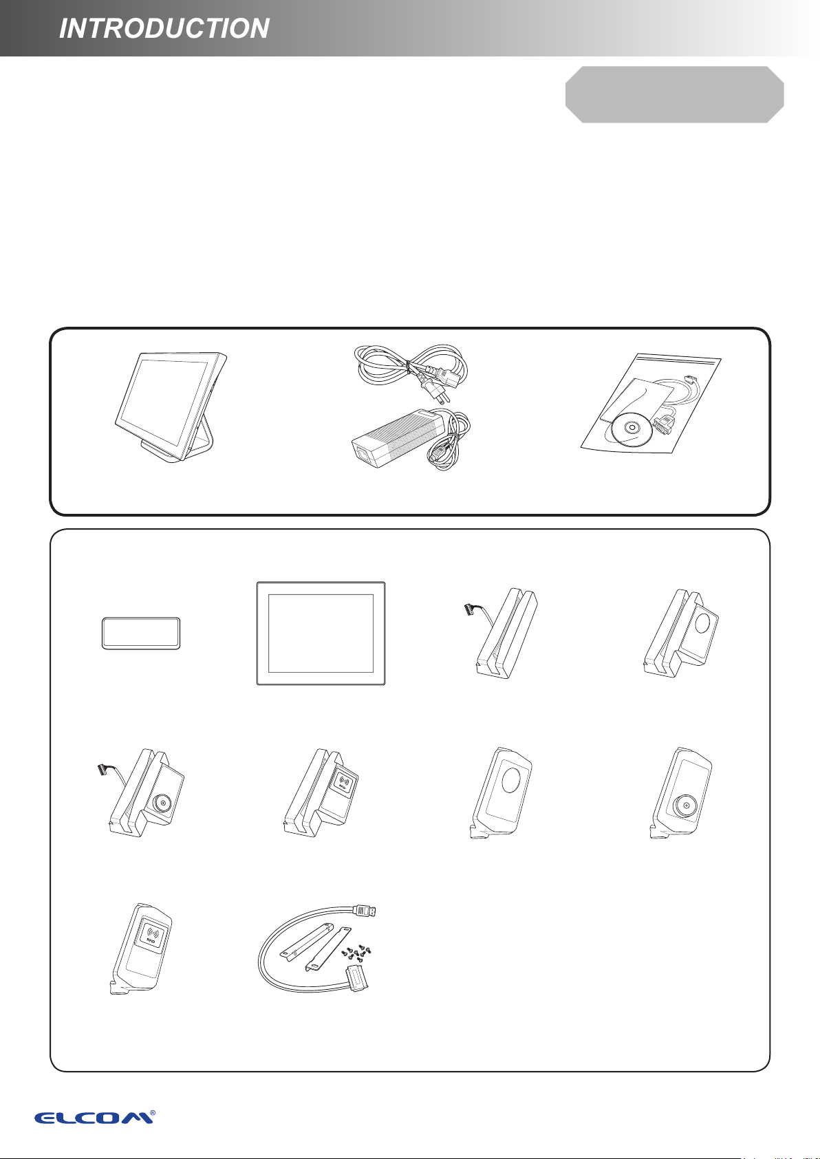
Chapter 1: Introduction
Package Contents
Before setting up your Touch Terminal, check that the package contains the following items. If any
of the items is missing or damaged, contact your vendor immediately.
Quick
Installation Guide
Touch Terminal
Optional Accessories
Customer Display
(VFD)
MSR + iButton
Identication Reader
Power Cord & Adapter
Secondary LCD
Display (10"/15”)
MSR + RFID
Identication Reader
MSR Reader MSR + Fingerprint
Fingerprint
Identication Reader
Accessory Kit
Identication Reader
iButton Identication
Reader
RFID Identication
Reader
Secondary Hard Disk
Drive Installation Kit
8
Page 9

INTRODUCTIONINTRODUCTION
INTRODUCTION
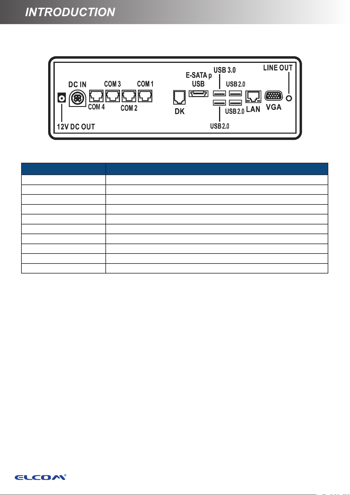
Overview of Wonder Series
The gures in this section illustrate the components (including input and output ports) located at
the front and rear of your Touch Terminal.
Front View
Rear View
Standard Type
Standard Type
9
Page 10
INTRODUCTION
INTRODUCTION
I/O Ports
Item Description
DC OUT jack 12V DC power output
DC IN jack 24V DC power input
COM ports COM1/2/3/4 connectors
DK port Cash Drawer output
E-SATAp port E-SATA + USB connector
USB2.0 ports USB2.0 connectors
USB3.0 ports USB3.0 connectors
LAN port Gigabit LAN connector
VGA port VGA output connector
Line Out port Audio line output connector
10
Page 11

INTRODUCTIONINTRODUCTION
INTRODUCTION
Physical Dimensions
Standard Display
11
Page 12

INTRODUCTION
INTRODUCTION
VFD Customer Display
12
Page 13

INTRODUCTIONINTRODUCTION
INTRODUCTION
10” Secondary LCD Display
13
Page 14

INTRODUCTION
INTRODUCTION
15” Secondary LCD Display
14
Page 15

INTRODUCTIONINTRODUCTION
INTRODUCTION
Specications
Touch Terminal Specications
Model number
LCD & Touch Panel
LCD Panel 15” LED-backlit display
Resolution 1024 x 768 (default)
Brightness 250 cd/m
Touch Screen Flat Projected Capacitive Touch (USB)
System Conguration
®
CPU
Intel
Chipset SoC
Main Memory 204Pin DDR3L RAM *1 slots, up to 8GB
Storage 1 x 2.5” SATA HDD or 1 x 2.5" SSD
I/O Ports
USB2.0 3
USB3.0 1
Celeron® J1900 2.0GHz/2.4GHz (burst) (Quad-core)
2
Wonder 615
eSATAp/USB2.0 combo 1
RJ45 COM 4
Gigabit Ethernet 1
Line out 1
Speaker 1
VGA 1
1
RJ12 cash drawer
DC12V out 1
DC24V in 1
Powering System
Power Supply
Power Button 1 x System on/off trigger
(Dual cash drawer support, 12V/24V selectable,
OPOS driver support)
External DC power adapter. AC100 to 240V full range.
( DC19V / 65W )
Physical Dimensions
Dimension (L x W x D) 323*370*200mm
15
Page 16

INTRODUCTION
INTRODUCTION
Model number
Safety & Environment
Product Certication CE / FCC / CB / LVD certicated
Operation Temperature 0°C to 40°C
Storage Temperature -25°C to 70°C
Wonder 615
O/S Compatibility
Windows 7/ POSReady 7 / Windows 10/ Linux Kernel 3.0 or above
Peripherals Specications
2nd LCD Display
Model no. KEKLC-3314A
LCD Panel 10” LED backlight
Touch N/A
Resolution 1024x768
Aspect Ratio 4:3
Viewing Angle 85° (H) / 85° (V)
Response Time 25ms (typical)
Contrast Ratio 500:1 (typical)
Brightness 350 nits
Interface USB
Power Supply 2-port USB Power Cable
16
Page 17

INTRODUCTIONINTRODUCTION
INTRODUCTION
15" LCD Display
Model no. KEKLC-3316A
LCD Panel 15"
Touch N/A
Resolution 1024x768
Aspect Ratio 4:3
Viewing Angle 80° (H) / 80° (V)
Response Time 8ms (typical)
Contrast Ratio 600:1
Brightness 250 cd/m2
Interface VGA
Power Supply 12V DC / 1.5A
Vacuum Fluorescent Display (VFD)
Model no. KMOTK-0091A
Display Method Vacuum Fluorescent Display (VFD)
Brightness 500-1000 cd/m2
Number of characters 40(20 columns x 2 lines)
Character size
6.75 (H) X 3.75 (W) mm
Character format 5 x 7 dot matrix, cursor
Character type 95 Alphanumeric, 32 International characters
Dot size 0.55 (W) X 0.75 (H) mm
Viewing Angle Max. 90°
Horizontal Rotation Max.355°
Interface RS232
17
Page 18

INTRODUCTION
INTRODUCTION
Single Identication Reader
MSR Reader
Model no. IE-10L
ISO Track 1/2/3 single/dual/ triple tracks of magnetic card, support ANSI/
MSR
ISO Standards7810, 7811 1/5, 7812 & 7813. USB HID Keyboard mode
interface
Fingerprint
Identication Reader
Model no. IE-10
Biometric
Fingerprint
Recognizer
iButton Detector
RFID Reader
NFC Reader
iButton Identication
Digital Personal U. are .U 4500B (Optical Type / Blue Light) Module.
Size: Approx. 57.7mm * 35.8mm*11.0mm.
Compatible with USB 1.1 / 2.0 (Full Speed).
USB HID Keyboard mode interface.
Dallas DS1990A compliment / With leading / ending programming
function.
USB HID Keyboard mode interface.
Frequency 13.56MHz.
ISO14443A card type MIFARE® 1K/4K/8K card type.
Read only.
USB HID Keyboard mode interface.
Frequency 13.56MHz.
ISO14443A, ISO1443B, ISO15693, PicoTag read UID and data, Felica
read UID.
MIFARE®:1-3cm, IS15693:2-4cm.
USB HID Keyboard mode interface.
Reader
RFID Identication
Reader
18
Page 19

INTRODUCTIONINTRODUCTION
INTRODUCTION
2-in-1 Identication Reader
MSR + Fingerprint
Identication Reader
Model no. IE-20
MSR
Biometric
Fingerprint
Recognizer
RFID reader
iButton Detector
Identication Reader
ISO Track 1/2/3 single/dual/ triple tracks of magnetic card, support ANSI/
ISO Standards7810, 7811 1/5, 7812 & 7813. USB HID Keyboard mode
interface
Digital Personal U. are .U 4500B (Optical Type / Blue Light) Module
Size: Approx. 57.7mm * 35.8mm*11.0mm Compatible with USB 1.1 / 2.0
(Full Speed). USB HID Keyboard mode interface
Frequency 13.56MHz. ISO14443A card type MIFARE® 1K/4K/8K card
type. Read only. USB HID Keyboard mode interface
Dallas DS1990A compliment / With leading / ending programming
function. USB HID Keyboard mode interface
MSR + iButton
MSR + Fingerprint
Identication Reader
19
Page 20

PREPARING FOR THE INSTALLATION
PREPARING FOR THE INSTALLATION
Chapter 2
Preparing For the Installation
Before you start installing Touch Terminal, read the following instructions.
• Wonder Series do not support PCI slot.
• Do not insert or remove any device or component from the Wonder Series while the power is
turned on.
• If using Wonder Series in a dusty environment, clean the Touch Terminal regularly.
• Only USB devices are Hot Swap capable. Be sure to turn off the power of the touch terminal
and the device before making any connection or disconnection.
• The spill proof design of Wonder Series conforms to IP65 standard (Front panel only).
• A bug may be found when installing Windows 2000 from a USB CDROM. When this occurs,
please go to the Microsoft website at http://support.microsoft.com/kb/838921 and nd the
solution.
• Always seek the help of authorized service personnel in disassembling the terminal. The
manufacturer will not be held responsible in the event of damage caused by an unauthorized
person.
• Before installation or disassembling of the terminal, ensure that the power is turned off.
Otherwise, electric shock may occur and may void the warranty.
• For systems preloaded with WEPOS/POSReady/Windows Embedded on the HDD (O/S
pre-installed as an option), the manufacturer provides an optional recovery DVD with the
preloaded operating system delivered with the Touch Terminal. The System Integrator
shall take care of software restoration after an OS recovery. A manufacturer-supplied USB
interface COMBO drive will be required for such action. Other brands of COMBO drive may
require a specic driver different from what is supported in the recovery DVD. Please use
the recovery DVD for rescue operation only. Using it otherwise may wipe out whatever
is stored in the HDD. All upgrade device drivers needed for manual installation are
available in the subfolder “\drivers” in the OS recovered HDD. Then follow the instructions
from your system integrator for software recovery.
• For SoC limitation, the W-615 is required to install at least one DDR3 memory module before
booting up the operating system. Be sure to install it in the DDR3 channel 1 socket.
20
Page 21

PREPARING FOR THE INSTALLATIONPREPARING FOR THE INSTALLATION
PREPARING FOR THE INSTALLATION
System Default Settings
The following is the information on default settings for Touch Terminal serial ports.
W-615
COM1 COM2 COM3 COM4 COM5 COM6
3F8 2F8 3E8 2E8 2F0 2E0
IRQ4 IRQ3 IRQ5 IRQ10 IRQ5 IRQ10
21
Page 22

PREPARING FOR THE INSTALLATION
PREPARING FOR THE INSTALLATION
Main Board Jumper Setting and Connector
Denition
W-615
Connector/Jumper Description
LINE OUT Audio line output connector
VGA VGA output
LAN1 LAN connector
USB1 USB2.0 *2 connector
USB2 USB3.0 *1 connector USB2.0 *1 connector
ESATA1 E-SATA + USB connector
CASHDRAW1 Cash Drawer output
COM1 COM1 connector
COM2 COM2 connector
COM3 COM3 connector
COM4 COM4 connector
DC24 24V DC power input
DC12 12V DC power output
JUSB1 USB port for USB Touch
JUSB2 USB port for POS input device
JUSB3 USB port for POS input device
22
Page 23

PREPARING FOR THE INSTALLATIONPREPARING FOR THE INSTALLATION
PREPARING FOR THE INSTALLATION
CN1 COM6 connector for RS-232 POS input device
123
123
123
123
135
246
135
246
135
LVDS1 2x15 LVDS connector
SPK_R1 Speaker connector
SPK_L1 Speaker connector
CONVERTER1 LED backlight inverter connector
SATA1 SATA Connector
SO-DIMM1 DDR3/DDR3L SO-DIMM
S2 Power Button Connector
LCD Panel Power Selection
JP1
Pin 1-2 Short/Closed
Pin 2-3 Short/Closed
JP2/ JP3/ JP6/ JP7/ JP8 : USB Power Selection
Pin 1-2 Short/Closed
Pin 2-3 Short/Closed
JP4: Clear CMOS Contents
Pin 1-2 Short/Closed
Pin 2-3 Short/Closed
JP9: Cash Drawer Power Selection
Pin 1-2 Short/Closed
Pin 2-3 Short/Closed
JP11 : COM 2 D-SUB PIN9 VOLTAGE SELECT
1-2=0V / R1
3-4=+5V
5-6=+12V
JP12: COM 3 D-SUB PIN9 VOLTAGE SELECT
3.3V
5V
5VSB
5V
Normal
Clear CMOS
24V
12V
Default = 0V
1-2=0V / R1
3-4=+5V
5-6=+12V
JP13: COM 4 D-SUB PIN9 VOLTAGE SELECT
1-2=0V / R1
3-4=+5V
246
5-6=+12V
Default = 0V
Default = 0V
23
Page 24

PREPARING FOR THE INSTALLATION
PREPARING FOR THE INSTALLATION
Voltage Output Denition
W-615
Connector with Voltage Output Location Power Support
th
COM 1 for extension interface (9
COM 2 for extension interface (9
COM 3 for extension interface (9
COM 4 for extension interface (9th PIN of DB-9) Main Board
Standard USB2.0 Ports
PIN of DB-9) Main Board
th
PIN of DB-9) Main Board
th
PIN of DB-9) Main Board
Main Board, Signal
Convergence Board;
Power Switch Board
DC5V/DC12V
Select by BIOS
DC5V/DC12V
Select by jumper
DC5V/DC12V
Select by jumper
DC5V/DC12V
Select by jumper
DC5V / 500mA
24
Page 25

PREPARING FOR THE INSTALLATIONPREPARING FOR THE INSTALLATION
PREPARING FOR THE INSTALLATION
Setting the LCD Brightness
W-615
1.Press <F2> when system boot. Select <Advanced> tab, then select <Video conguration>.
2.Select <Brightness Control Level> to adjust LCD brightess level.
25
Page 26

HARDWARE INSTALLATION
PREPARING FOR THE INSTALLATION
Setting the Serial Port (COM 1) Voltage
1. Press <F2> when system boot. Select <Advanced>
tab, then select <S10 FINTEK F81866A>.
2. Select <Voltage Selectore, then click <OK>
26
Page 27

HARDWARE INSTALLATIONPREPARING FOR THE INSTALLATION
HARDWARE INSTALLATION
Chapter 3
Hardware Installation
Installing the Power Cord, Power Adapter, and
Network Cable
1. Place the Touch Terminal on a soft and at surface, with the LCD panel facing down.
Remove the cable compartment cover. (a)
2. Connect the network cable to the LAN port. Then connect the power adapter to the DC IN
jack. (b)
3. Route the power adapter and the network cable through the cable compartment. (c)
4. Align and install the cable compartment. (d)
5. Connect the power adapter to the power cord. Then plug the other end of the power cord to
an electrical outlet. (e)
6. Connect the network cable to a hub or switch. (f)
e
Be sure to turn off the power of the Touch Terminal before making any
connection or disconnection.
f
c
b
a
d
• When removing the power adapter, be sure to hold the
end of power adapter rmly and pull it out.
27
Page 28

HARDWARE INSTALLATION
HARDWARE INSTALLATION
Installing the Customer Display (Optional)
Be sure to turn off the power of the Touch Terminal before making any
connection or disconnection.
To congure the COM port voltage setting to +5V, refer to "Main Board Jumper
Setting and Connector Denition" on page 23
1. Place the Touch Terminal on a soft and at surface, with the LCD panel facing down.
Remove the cable compartment cover. (a)
2. Remove the four screws on the stand. (b)
3. Remove the stand. (C)
4. Remove the supportive tape from the stand. (d)
5. Remove the four screws on the stand cover. (e)
6. Remove the stand cover. (f)
7. Align and install the customer display into the four threaded standoffs on the stand. (g)
8. Secure the customer display to the stand with the four screw nuts. (h)
9. Route the customer display’s interface cable through the cable guides on the stand and
through the cable compartment as illustrated. (i)
10. Connect the customer display’s interface cable to the RJ-45 COM port on Touch Terminal. (j)
a
b
c
d
f
h
g
i
e
j
11. Reverse steps 6 through 1 to complete installing the customer display.
28
Page 29

HARDWARE INSTALLATIONHARDWARE INSTALLATION
HARDWARE INSTALLATION
Installing the Secondary LCD Display (Optional)
Be sure to turn off the power of the Touch Terminal before making any
connection or disconnection.
1. Place the Touch Terminal on a soft and at surface, with the LCD panel facing down.
Remove the cable compartment cover. (a)
2. Remove the four screws on the stand. (b)
3. Remove the stand. (C)
4. Remove the supportive tape from the stand. (d)
5. Remove the four screws on the stand cover. (e)
6. Remove the stand cover. (f)
7. Align and install the secondary LCD display into the four threaded standoffs on the stand. (g)
8. Secure the secondary LCD display to the stand with the four screw nuts. (h)
9. Route the secondary LCD display’s power cable and USB cable through the cable guides on
the stand as illustrated. (i)
10. Connect the secondary LCD display’s power cable and USB cable to the corresponding
ports on Touch Terminal. (j)
a
b
c
d
f
h
g
i
e
j
11. Reverse steps 6 through 1 to complete installing the secondary LCD display.
29
Page 30

HARDWARE INSTALLATION
HARDWARE INSTALLATION
HARDWARE INSTALLATION
31
Installing the VESA Mount (Optional)
NOTE:
• Use only wall mount kits approved by the manufacturer. Wall mount kits are sold
separately.
• The Touch Terminal device is compatible with a VESA mounting hole pattern of
75x75mm.
1. Place the Touch Terminal on a soft and at surface, with the LCD panel facing down.
Remove the cable compartment cover. (a)
2. Remove the four screws on the stand. (b)
3. Remove the stand. (c)
4. Align and install the mount bracket on the back of the Touch Terminal. (d)
5. Secure the mount bracket to the Touch Terminal with the four screws. (e)
6. Drill four small holes on the mounting location and insert the plastic washers into the holes. (f)
7. Align by the screw holes and then install the wall bracket on the wall. (g)
8. Secure the wall bracket to the wall with the four supplied screws. (h)
9. Align and hook the Touch Terminal to the wall bracket, and then push down to secure it into
place. (i)
a
b
c
d
e
f
h
i
g
10. Replace the cable compartment cover for storing the stand assembly. (a)
Be sure to turn off the power of the Touch Terminal before making any
connection or disconnection.
1. Remove the identication reader compartment cover. (a)
2. Firmly connect the identication reader connector into the slot inside the compartment. (b)
3. Align and install the identication reader onto its compartment. (c)
4. Secure the identication reader to the Touch Terminal using the two screws. (d)
b
d
c
a
30
Page 31

HARDWARE INSTALLATION
Installing the VESA Mount (Optional)
NOTE:
• Use only wall mount kits approved by the manufacturer. Wall mount kits are sold
separately.
• The Touch Terminal device is compatible with a VESA mounting hole pattern of
75x75mm.
1. Place the Touch Terminal on a soft and at surface, with the LCD panel facing down.
Remove the cable compartment cover. (a)
2. Remove the four screws on the stand. (b)
3. Remove the stand. (c)
4. Align and install the mount bracket on the back of the Touch Terminal. (d)
5. Secure the mount bracket to the Touch Terminal with the four screws. (e)
6. Drill four small holes on the mounting location and insert the plastic washers into the holes. (f)
7. Align by the screw holes and then install the wall bracket on the wall. (g)
8. Secure the wall bracket to the wall with the four supplied screws. (h)
9. Align and hook the Touch Terminal to the wall bracket, and then push down to secure it into
place. (i)
a
b
c
e
i
d
f
g
h
10. Replace the cable compartment cover for storing the stand assembly. (a)
31
Page 32

<CHAPTER TITLE>
HARDWARE INSTALLATION
Chapter 4
123
Frequently Asked Questions (FAQ)
Question 1: How do I clear CMOS?
W-615
Answer: To clear CMOS, do the following:
1. Turn off power and pull out the power cord.
2. Insert the jumper cap to clear CMOS PIN and remove the jumper cap
from clear CMOS PIN. (Remark)
3. Switch on the power again.
4. Press F2 to enter CMOS setting and load optimized defaults.
5. Save changes and reboot the system.
Remark
JP4: Clear CMOS Contents
Pin 1-2 Short/Closed
Pin 2-3 Short/Closed
32
Normal
Clear CMOS
 Loading...