

Page 1

Modular transfer system
TLM 2000
User Manual
&
Maintenance guide
Translation of the original manual, version 02 / I02-121
Page 2

I02-121 User manual & maintenance guide Version 02 (translation of the original manual)
of TLM 2000
Table of contents
1. General information ........................................................................................................................ 1
1.1 Important remarks ............................................................................................................... 1
1.2 Applicable standards ............................................................................................................ 1
1.3 Applications ......................................................................................................................... 1
1.4 Conditions of use ................................................................................................................. 1
1.5 Safety instructions ............................................................................................................... 2
1.6 Safety instructions regarding the motor .............................................................................. 2
1.7 Additional information ......................................................................................................... 2
2. Technical specifications ................................................................................................................... 3
3. Commissioning ................................................................................................................................ 3
4. Maintenance.................................................................................................................................... 5
5. Changing the motor ....................................................................................................................... 14
5.1. Chain drive ......................................................................................................................... 14
5.2 Direct drive ......................................................................................................................... 17
6. changing the chain ........................................................................................................................ 21
7. Changing the flat belt .................................................................................................................... 24
8. Responsability ............................................................................................................................... 26
9. Customer service ........................................................................................................................... 26
10. Appendix ........................................................................................................................................ 28
10.1. Maintenance schedule ................................................................................................... 28
10.2 Quality and environmental commitment : ISO certifications ........................................ 29
10.3 Spare parts list ................................................................................................................ 30
10.4 Wearing parts list for maintenance................................................................................ 30
Page 3

I02-121 User manual & maintenance guide Version 02 (translation of the original manual)
of TLM 2000
Version tracking:
Version
Date
Description of modifications
Prepared by
Approved by
00
04/06/13
Initial (translation)
S. GUILLAUD-BATAILLE
01
01/10/15
-
S. GUILLAUD-
BATAILLE
-
02
19/09/18
Upgrade of the safety instructions + 2015
edition of ISO 9001 and 14001 standards:
deletion of expired certificates
S. MAIRET
S. MAIRET
Page 4

I02-121 User manual & maintenance guide Version 02 (translation of the original manual)
of TLM 2000 Page 1 sur 41
1. GENERAL INFORMATION
1.1 Important remarks
The following instructions will be used as technical documentation for the manufacturer of the
final machine. elcom is the supplier of this TLM 2000 transfer system sub-assembly .
The manufacturer of the final machine must make sure that:
- All safety equipment is provided and functional,
- Regular checks are carried out,
- All danger (pinching, squashing) due to moving parts is controlled,
- The documentation is complete.
1.2 Applicable standards
According to the 2006/42/CE European directive, elcom transfer systems are considered as partly
completed machines. They are therefore not subject to an EC declaration of conformity but are
the subject of a declaration of incorporation. The latter is transmitted at the time of delivery,
accompanied by the exploded view of the motorized equipment.
However, the following standards are taken into account during the design and the manufacturing
of the elcom transfer systems:
– The European Machinery Directive 2006/42/CE
– The European Low Voltage Directive73/23/CE
elcom ensures an adequate follow-up and products quality formalized by the ISO 9001
certification.
For environmental reasons, elcom also meets the requirements of the ISO 14001 standards.
1.3 Applications
The elements of the linear TLM 2000 transfer systems are designed to carry and position
workpiece carriers according to the end customers’ configuration.
They are intended to be incorporated the customers' production line.
1.4 Conditions of use
The elements of the TLM 2000 transfer systems are suited for a use in normal industrial areas
such as a final assembly plant or equivalent, in a dry environment.
They are not suited for transporting materials such as sand, balls or grain.
The maximum load applicable on the transfer system is mentioned in the catalog and must never
be ignored.
To ensure a proper functioning of the transfer system on a maximum period of time, you must
follow this advice:
- Use temperature between 0 and 40°C (30 and 140°F),
- Avoid dusty or smoky atmosphere,
- Avoid accumulation of sharp objects on the transfer system,
- Avoid setting the machine in direct exposition to UV rays.
Page 5

I02-121 User manual & maintenance guide Version 02 (translation of the original manual)
of TLM 2000 Page 2 sur 41
1.5 Safety instructions
Safety rules regarding transfer systems, especially the ones concerning the electrical
devices, must be followed during all the use phases: mounting, transport, production.
Disregarding these rules would be regarded as a wrong use of the machine.
Using the transfer system in an explosive atmosphere can have a negative impact on
the transfer system and is strongly discouraged.
Never perform any maintenance on your own. Another worker must be present at all
time in order to shut the power down or perform first aid actions if needed.
Changing the motor position or removing security parts must only be done when the
transfer system is unplugged from any power supply.
When carrying maintenance or handling tasks while the transfer system is operating
(belt tension setting), take care not to slide your hand between the belt and the belt
support in order to avoid any accident.
All the different types of positioning units include several mobile parts driven by
pneumatic cylinders. Therefore, they must be well protected in the end-user
machine in order to avoid any risks of pinching or squashing. We recommend
mounting a protective housing around it. In case of manual shift, the final machine
can not be used without the protections installed at the indexing and stop station
1.6 Safety instructions regarding the motor
In case of a power failure, turn off the transfer system: it could restart automatically
when the power comes back, which could cause damages and even injuries to the
operator.
1.7 Additional information
These instructions aim at ensuring the safety of the people and the proper functioning of the
transfer system. If you wish to use the transfer system in any other conditions, please do not
hesitate to contact us.
Other information is available on our website, in the documentation section.
http://elcom-automation.com/transfers/documentation
Page 6

I02-121 User manual & maintenance guide Version 02 (translation of the original manual)
of TLM 2000 Page 3 sur 41
2. TECHNICAL SPECIFICATIONS
- Maximum load on a workpiece carrier: 10 kg
- Maximum accumulated load on the transfer system: 100 kg for a maximum 6 m unit.
- Electrical power supply of the motors: 380V three-phase
- Motor power: V 9 m /min = 0.25 Kw
(V = belt speed) V 15 m /min = 0.37 Kw
V 19 m /min = 0.55 Kw
Air pressure supply = 5 to 6 bars
Every cylinder must be equipped with a flow limiter.
- Sound emission < 70 dB
- Weight of each part: See our catalogue Modular Transfer Systems & Flat belt conveyors.
http://elcom-automation.com/transfers/documentation
Warning: All load exceedance can lead to a premature wear of the belt or any other
parts.
3. COMMISSIONING
3.1 Receipt
When receiving the transfer system, check if the packaging has not suffered any damage
and that the machine is in perfect conditions.
The transfer system can be supplied in kit; it then needs to be assembled.
3.2 Transfer elements
When handling the equipment and parts, take special care to avoid shocks.
1. Assemble the parts according to the lay-out of the line with the delivered fastening
parts,
2. Level perfectly the conveying units while checking that the belts are properly laid on the
belt guide,
Page 7

I02-121 User manual & maintenance guide Version 02 (translation of the original manual)
of TLM 2000 Page 4 sur 41
3. Ensure the perfect stability of the whole line. To achieve this and according to the lay-
out of the line, it may be necessary to perform ground fastenings,
4. Check the settings of the motor magneto-thermic circuit breakers,
5. Check the running direction of the belt without any load,
6. Adjust the cams and the selectors using a workpiece carrier,
7. Start the transfer system with all the workpiece carriers on.
3.3 Stopper
1. Place the stopper right in the middle of the two profiles of the system,
2. Adjust the sensor for the detection of the workpiece carriers,
3. Adjust the flow control units.
3.4 Positioning unit
1. Put the positioning unit right in the middle of the two profiles of the system,
2. Adjust the sensor for the detection of the workpiece carriers,
3. Check on the high position that the pins of the workpiece carrier are free,
4. Lubricate the positioning units fingers with a fine layer of grease (see Maintenance),
5. Adjust the flow controllers.
Note: For the heavy positioning unit, check the lubrication of the drawer (see
Maintenance).
All the different types of positioning unit include several mobile parts driven by
pneumatic cylinders. Therefore, they must be well protected on the end-user
machine in order to avoid any risk of pinching or squashing. We recommend
mounting a protective housing.
3.5 Workpiece carrier
1. Check that the springs of the pins located under the carrier are working properly.
2. Check that no part goes over the lower surface of the workpiece carrier.
Page 8
I02-121 User manual & maintenance guide Version 02 (translation of the original manual)
of TLM 2000 Page 5 sur 41
4. MAINTENANCE
General visual check
Approximately every 500 hours, check the following points to ensure the proper functioning of
the transfer system:
Belt wear
Regularly verify visually the state of the belt and especially the welding area.
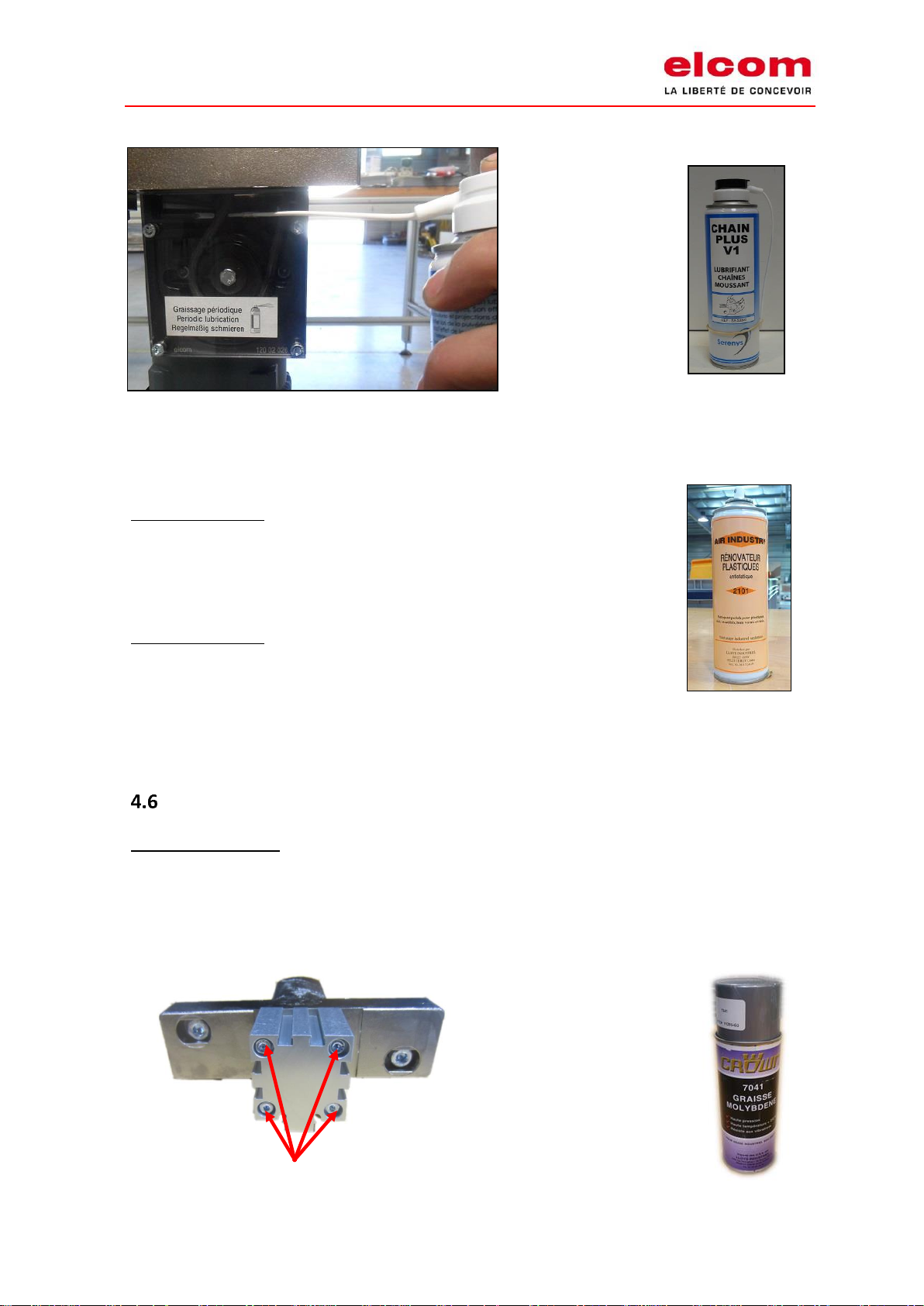
Passageways of the workpiece carriers
The friction of the pins while operating can make some marks appear. Those marks may over the
long term require the part replacement.
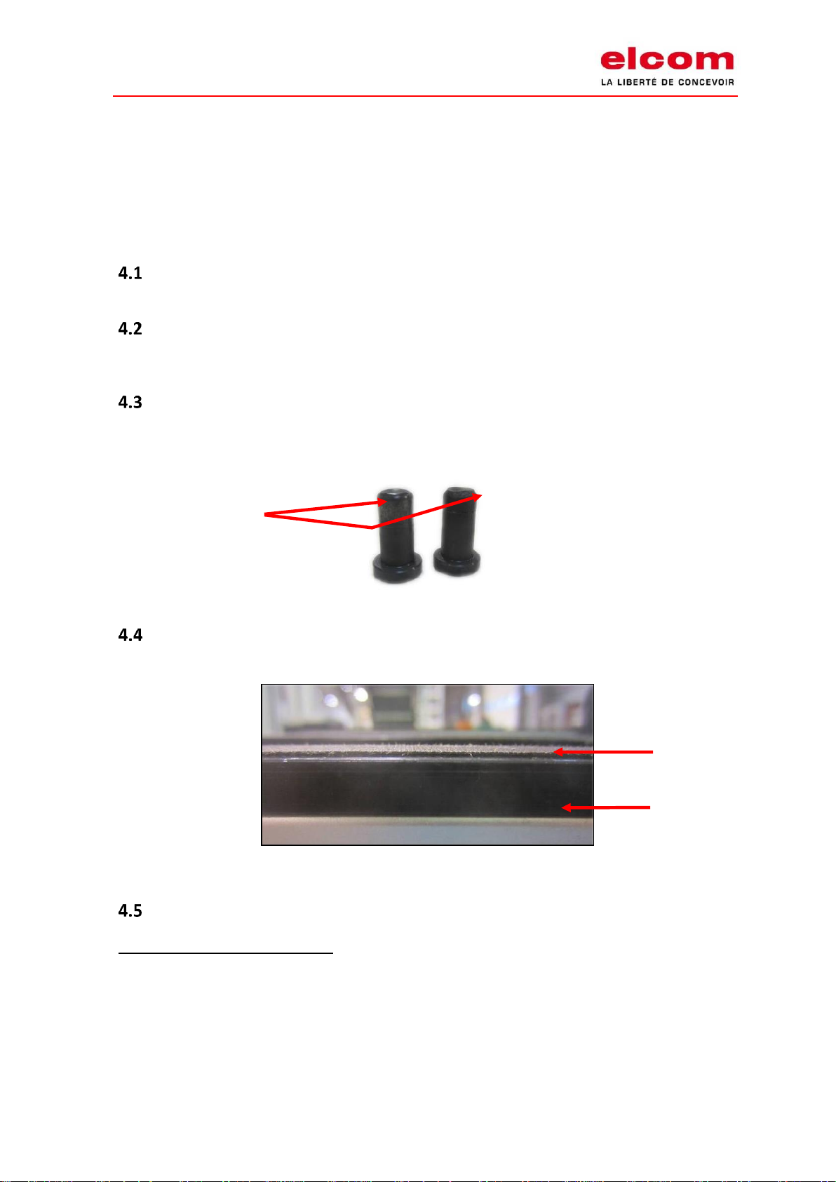
Pins
Pins are sensitive to wear, especially if the load is heavy on the workpiece carrier. Wear can be
noticed as soon as a loss of efficiency in the guiding of the workpiece carrier occurs.
Wear of the belt guide
Belt guide must be replaced as soon as wear marks or friction on the belt start to appear.
Transfer parts
After the first 100 hours of use:
Lubricate the chain. No disassembly is needed for this operation.
Use the grease ref. 800 00 006 (Chain plus V1 spray).
Wear area of the pins
Belt
Belt guide
Page 9
I02-121 User manual & maintenance guide Version 02 (translation of the original manual)
of TLM 2000 Page 6 sur 41
For direct conveying units, no lubrication is necessary.
Every 200 hours:
Remove dust from of the whole system.
Use the product ref. 800 00 003 (Polish plastics Air Industry 2101).
Every 500 hours:
Lubricate the chain.
For direct conveying units, no lubrication is necessary.
Check visually the wear of the belts.
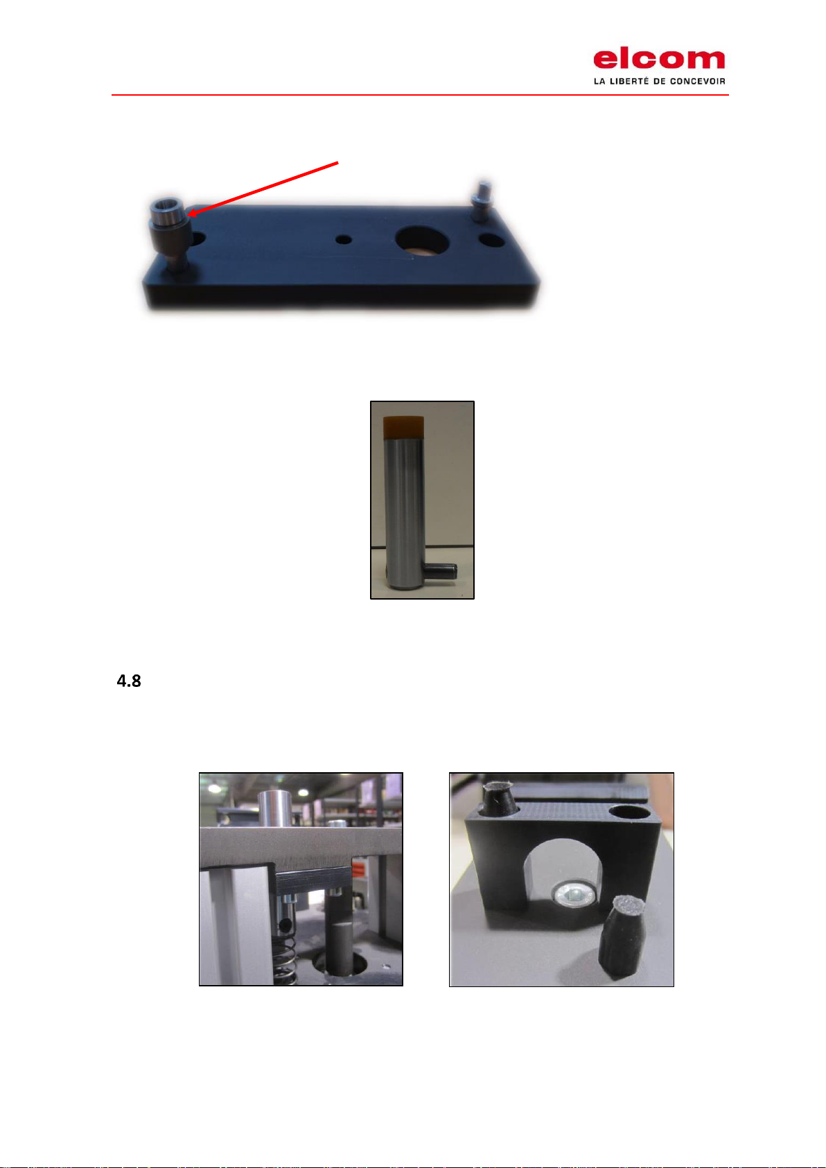
Stoppers
Every 1,000 hours:
Lubricate the rod of the stopper ref. 120 23 011
Use the grease ref. 800 00 002 (Crown ref. 7041 spray).
Page 10

I02-121 User manual & maintenance guide Version 02 (translation of the original manual)
of TLM 2000 Page 7 sur 41
To lubricate the cylinder without removing the stopper from the system, remove the four screws
mentioned above to take out the rod and cylinder set.
Positioning unit
All types except heavy positioning unit.
Every 1,000 hours:
Lubricate the positioning unit fingers with a film of grease.
Use grease ref. 800 00 002 (Crown ref. 7041 spray).
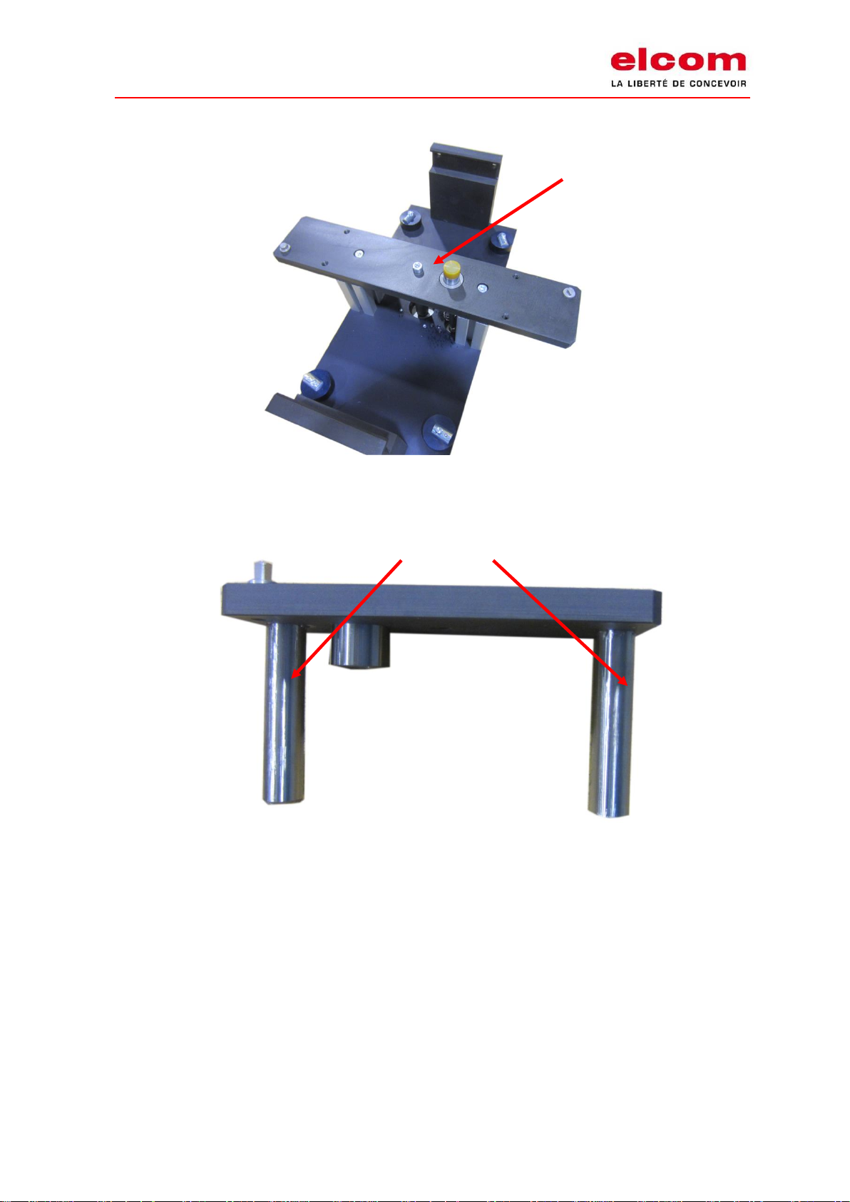
Check the lubrication of the guiding shafts
To reach the guiding shafts, remove the central fastening screw from the plate to release it from
the positioning unit without removing the positioning unit from the transfer system.
Page 11
I02-121 User manual & maintenance guide Version 02 (translation of the original manual)
of TLM 2000 Page 8 sur 41
Plate fastening screw
Guiding shafts to lubricate
Page 12
I02-121 User manual & maintenance guide Version 02 (translation of the original manual)
of TLM 2000 Page 9 sur 41
For a quick lubrication of the guiding shafts, it is also possible to access them, without any
disassembly, only by pulling the plate.
Changing the pins (locating/centering pins)
Extract the previous pins from the press.
Install the new pins in the press while using a bush of a workpiece carrier ref. 120 03 006 as a
support (insert the pin in the bush and then place them on the positioning unit plate).
Pins
Page 13
I02-121 User manual & maintenance guide Version 02 (translation of the original manual)
of TLM 2000 Page 10 sur 41
Lubricate the positioning unit finger with a film of grease.
Case of a damped stopper
It is possible to replace the damping rubber stoppers. Remove the 4 screws to access the U-shape
part including the stoppers.
Bush (ref. 120 03 006)
Page 14
I02-121 User manual & maintenance guide Version 02 (translation of the original manual)
of TLM 2000 Page 11 sur 41
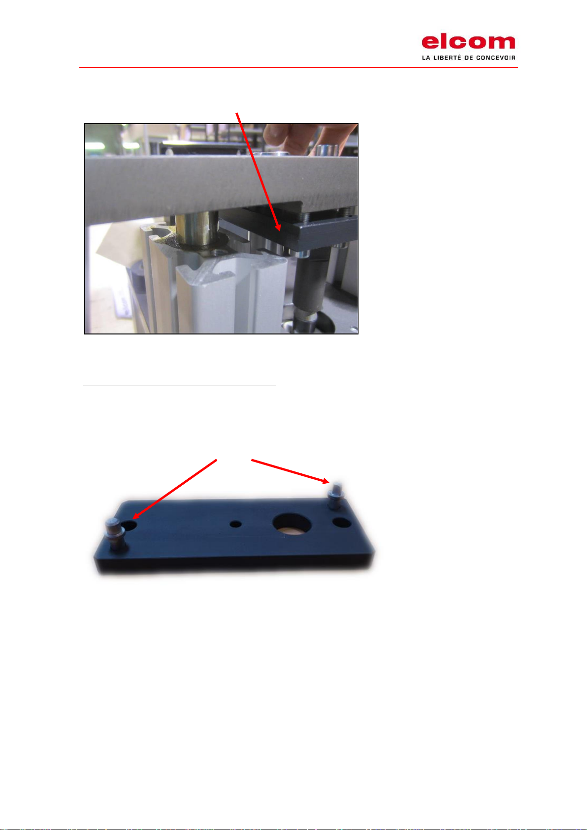
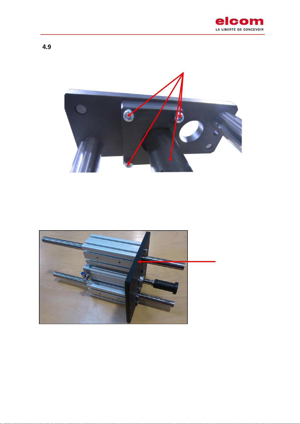
Lift positioning unit
The operating mode remains the same as the standard positioning unit. It is not necessary to
disassemble the lift positioning unit from the transfer system for this maintenance.
Release the plate to access the guiding shafts and cylinder by removing the fastening screws.
In order to centre the guiding shafts on the plate, the centering device ref. 800 15 001 can be
used.
Plate
Page 15

I02-121 User manual & maintenance guide Version 02 (translation of the original manual)
of TLM 2000 Page 12 sur 41
Heavy positioning unit
For the maintenance of the heavy positioning unit, it is necessary to remove it from the transfer
system.
Every 1,000 hours:
Then, remove the screws located underneath the heavy positioning unit to access the drawer.
Lubricate the drawer (inside and outside) ref. 120 08 010 (grease Gulf Crown EP2).
Centering device
Page 16

I02-121 User manual & maintenance guide Version 02 (translation of the original manual)
of TLM 2000 Page 13 sur 41
Lubricate the positioning unit finger with a film of grease.
Use the grease ref. 800 00 002 (Crown ref. 7041 spray).
Drawer
Support block
Support block
Drawer
Page 17

I02-121 User manual & maintenance guide Version 02 (translation of the original manual)
of TLM 2000 Page 14 sur 41
Changing the pins (locating/centering)
Extract the previous pins from the press.
Install the new pins in the press while using a bush of a workpiece carrier ref. 120 03 006 as a
support (insert the pin in the bush and then place them on the positioning unit plate).
Other transfer parts
The others parts of the transfer system do not need any maintenance. A visual check, looking for
wear or broken parts is recommended from time to time.
5. CHANGING THE MOTOR
5.1. Chain drive
Remove the cap.
Loosened screws
Cap
Loosened screws
Page 18

I02-121 User manual & maintenance guide Version 02 (translation of the original manual)
of TLM 2000 Page 15 sur 41
Remove the flange, the chain tensioner and the spring.
Flange
Loosened screws
Tensioner
Spring
Page 19

I02-121 User manual & maintenance guide Version 02 (translation of the original manual)
of TLM 2000 Page 16 sur 41
Space out the motor shaft on the sprocket side.
Shaft
Page 20

I02-121 User manual & maintenance guide Version 02 (translation of the original manual)
of TLM 2000 Page 17 sur 41
Loosen the four screws fastening the motor on the block.
For reassembly, follow the previous steps in reverse order. Do not forget to lubricate the shaft.
Put the cap on the new motor.
Lubricate the chain (see Maintenance).
5.2 Direct drive
Disassembly
Remove the screw CHC M5x30 holding the locking clip.
Block ref. 120 02 025
Screws
Page 21

I02-121 User manual & maintenance guide Version 02 (translation of the original manual)
of TLM 2000 Page 18 sur 41
Slide the motor and the plate on the motor shaft to remove it.
Locking clip
Plate
Shaft
Page 22

I02-121 User manual & maintenance guide Version 02 (translation of the original manual)
of TLM 2000 Page 19 sur 41
Remove the plate by loosening the screws.
Reassembly
Lubricate the shaft.
Fasten the plate on the motor with the four screws.
Install the motor on the motor shaft.
Align the groove of the anti-rotation axis with the slot of the plate.
Slide the whole until the locking clip is perfectly positioned in countersink of the plate.
Screws
Plate
Page 23

I02-121 User manual & maintenance guide Version 02 (translation of the original manual)
of TLM 2000 Page 20 sur 41
Anti-rotation axis:
Widest gap on the side of the plate.
Tighten the screw CHC M5x30 holding the locking clip ref. 12011007.
Screw
Page 24

I02-121 User manual & maintenance guide Version 02 (translation of the original manual)
of TLM 2000 Page 21 sur 41
6. CHANGING THE CHAIN
Take the protecting cover off.
Remove the chain tensioner and the spring.
Remove the chain cover ref. 120 02 015.
Space out the motor shaft on the sprocket side.
Tension er
Spring (ref. 120 02 209)
Chain cover
Page 25

I02-121 User manual & maintenance guide Version 02 (translation of the original manual)
of TLM 2000 Page 22 sur 41
Cut the chain.
Shaft
Page 26

I02-121 User manual & maintenance guide Version 02 (translation of the original manual)
of TLM 2000 Page 23 sur 41
Mount a new chain with a quick release system (pay attention to the mounting direction of the
quick release system).
To reassemble, follow the previous steps in reverse order.
Lubricate the chain (see Maintenance).
Quick release system
Page 27

I02-121 User manual & maintenance guide Version 02 (translation of the original manual)
of TLM 2000 Page 24 sur 41
7. CHANGING THE FLAT BELT
Calculate the belt required length for a single
unit:
[(L-100) x 2 + 173] x 0.98
L = total length of the transfer system, including
the return.
Cut the first bevel.
Trace the zero point.
Cut the right length.
Cut the second bevel with the same bevelling
device.
Do not forget to take the length of the bevel into account when calculating the
length of the belt. The superposition of this length must be subtracted from the
total length.
Place the belt on the transfer system.
a) Pull
b) Push
Belt position
Belt position
Driving direction
Driving direction
Page 28

I02-121 User manual & maintenance guide Version 02 (translation of the original manual)
of TLM 2000 Page 25 sur 41
Stretch the belt until the bevels are juxtaposed.
Clean both sides of the bevels with alcohol.
Spray glue on both sides of the bevels (Glue expiration date: 1 month after opening. We advise
you to write the opening date on the glue bottle. Do not keep it later than one month after this
date).
Place the thermic press correctly aligned with the belt.
Fasten the belt on the press.
Use 2 belt pieces to align perfectly the 2 bevels.
Close the press and let warm up for 35 minutes at 120°C (250°F).
Page 29

I02-121 User manual & maintenance guide Version 02 (translation of the original manual)
of TLM 2000 Page 26 sur 41
Let the thermic press cool down for 30 minutes.
Remove excess glue with some abrasive paper.
Loosen the belt.
8. RESPONSABILITY
elcom cannot be held responsible for any damages or harms due to non-authorized modification
of any parts, especially the safety parts.
Only original components can be used for maintenance or fixing.
elcom cannot be held responsible for any malfunction if some spare parts have been used without
the validation of elcom.
elcom reserves the right to make improvements and technical modifications without any further
notice.
9. CUSTOMER SERVICE
Do not hesitate to contact us for any question or advice. We will be glad to assist you.
Tel: + 33 (0)4 74 43 99 61
E-mail: elcom@elcom.fr
Page 30

I02-121 User manual & maintenance guide Version 02 (translation of the original manual)
of TLM 2000 Page 27 sur 41
Address : 1 rue Isaac Asimov
ZAC de la Maladière
38300 Bourgoin-Jallieu
France
Page 31

I02-121 User manual & maintenance guide Version 02 (translation of the original manual)
of TLM 2000 Page 28 sur 41
Prior to any contact, please note down the serial number of the transfer system. This number can
be found on the transfer system sticker.
10. APPENDIX
10.1. Maintenance schedule
Maintenance of the modular transfer system TLM 2000
Frequency
Action
Component
Chapter
After the first 100 hours
To lubricate
Chain
4.1
200 hours
To dust
Transfer parts
4.1
500 hours
To check
Belt - Belt guide - Workpiece carriers
4.1
500 hours
To lubricate
Chain
4.1
1,000 hours
To lubricate
Stoppers
4.2
1,000 hours
To lubricate
Positioning units (shafts and cylinder)
4.3
1,000 hours
To lubricate
Heavy positioning units (shaft, drawer and cylinder)
4.5
Page 32

I02-121 User manual & maintenance guide Version 02 (translation of the original manual)
of TLM 2000 Page 29 sur 41
10.2 Quality and environmental commitment : ISO certifications
Our company is recognized according to the following ISO standards and their respective evolutions
since our first certification:
- Quality Management through ISO 9001 [since 2002]
- Environmental Management through ISO 14001 [since 2013]
All our current certificates are available for download in French, English and German on our website
http://elcom-automation.com/
Page 33

I02-121 User manual & maintenance guide Version 02 (translation of the original manual)
of TLM 2000 Page 30 sur 41
10.3 Spare parts list
Emergency spare parts
12000201
Belt 25 x 1.6 - Bande 25 x 1.6
12002015
Chain cover - Cache chaîne
12002019
Driving shaft - Arbre moteur
12002020
Driving sprocket - Pignon moteur
12002026
Cap -Flasque
12002027
Chain tensioner - Tendeur
12002029
Cover - Capot
12002032
Steel pulley 200 -Poulie 200 acier
12002033
Washer - Rondelle
12002035
Seal - Joint d'étanchéité flasque
12002036
Seal - Joint d'étanchéité flasque
12002040
Cap - Flasque
12002041
Cover -Capot
12002042
Chain tensioner - Tendeur
12002204
ASA 25/3 Chain - Chaîne + attache
12003003
Guide pin - Pion guidage
12003201
Spring - Ressort
12034201
Belt 12.5x1.5 - Bande retour 180°
11003201
Spring diam. 0.3 - Ressort diam. 0.3 -
80000004
Glue 40g - Colle 40g
10.4 Wearing parts list for maintenance
12000001
Belt guide -Guide bande
12000002
Cover - Cache
12000201
Belt - Bande 25 x 1.6
12000201A
Belt beveling - Biseautage bande
12001002
Idling block 200 moulded - Bloc renvoi 200 moulé
12001004
Idling pulley 200 - Poulie renvoi 200
12001005
Cover - Capot
12002003
Pulley washer - Rondelle poulie
12002015
chain cover - Cache chaine
12002019
Driving shaft - Arbre moteur
12002020
Driving sprocket - Pignon moteur
12002024
Washer - Rondelle
12002025
Driving block 200 moulded- Bloc entraînement 200 moulé
12002026
Cap - Flasque
Page 34

I02-121 User manual & maintenance guide Version 02 (translation of the original manual)
of TLM 2000 Page 31 sur 41
12002027
Chain tensioner - Tendeur
12002028
Pulley shaft 200 - Axe poulie 200
12002029
Cover -Capot
12002030
Protection cover - Plaque
12002031
Guide belt end - Cale
12002032
Steel pulley 200 - Poulie 200 acier
12002033
Washer - Rondelle
12002035
Seal - Joint d'étanchéité flasque
12002036
Seal - Joint d'étanchéité flasque
12002040
Cap - Flasque
12002041
Cover - Capot
12002042
Chain tensioner - Tendeur
12002043
Chain cover - Cache chaine avec pente
12002101A
Shaft diam.20 chromium steel - Arbre diam.20 acier chromé
12002202
Ball bearing 6004ZZ - Roulement 6004ZZ
12002204
ASA 25/3 Chain - Chaine + attache
12002204SF
Endless chain - Chaine sans fin
12002205A
Motor 9m - Moteur 9m 220V 1.27A .400V 0.73A
12002205B
Motor 15m - Moteur 15m 220V 2.15A .400V 1.23A
12002205C
Motor 19 m - Moteur 19m 220V 2.45A .400V 1.42A
12002205D
Seal for WA20 - Joint pour WA20
12002206
Bolt - Clavette
12002207
Bolt - Clavette
12002208
Axis screw - Vis axe
12002209
Spring - Ressort
12003003
Guide pin - Pion guidage
12003003I
Stainless steel pin - Pion inox
12003006
Bush - Canon
12003201
Spring - Ressort
12003203
Cap Diam.10 - Cache Diam.10
12003204
Cap Diam.15 - Cache Diam.15
12003205
Shock absorber -Tampon
12003206
Tampon 90 shore - Tampon 90 shore
12004002
Hook - Crochet
12004003
Positioning unit guide - Guide indexage
12004008
Spacer - Entretoise fixation
12004009
Positioning unit plate spacer - Entretoise plaque indexage
12004009F
Festo pos. unit plate spacer - Entretoise plaque indexage Festo
12004012
Positioning unit stopper rod - Tige butée indexage
12004013
Position. unit stopper finger - Doigt butee indexage
12004013F
Festo pos. unit stopper finger - Doigt butée indexage Festo
Page 35

I02-121 User manual & maintenance guide Version 02 (translation of the original manual)
of TLM 2000 Page 32 sur 41
12004014
Rod modification - Retouche tige
12004202
Cylinder 50-20 - Vérin 50-20
12005005
Rod rubbering - Caoutchoutage butée
12005006
Stopper rod -Tige butée
12005007
Finger - Doigt
12005007F
Festo finger - Doigt Festo
12005201
Bush 179 CSE 20 L - Canon 179 CSE 20 L
12005203
Cylinder 32-10 - Vérin 32-10
12006001
Jonction support - Support de liaison
12006002
Rail - Rail
12006003
Rail - Rail
12006005
Plate - Plaque
12006006
Left cover -Cache gauche
12006010
Right cover - Cache droit
12006011
Selector SG-SD – Sélecteur SG-SD
12006012
Selector EG-ED -Sélecteur EG-ED
12006013
Cam support -Support came
12007001
Selector - Left - Sélecteur gauche
12007001F
Festo Selector - Left - Sélecteur gauche Festo
12007002
Selector – right - Sélecteur droit
12007002F
Festo Selector - Left - Sélecteur droit Festo
12007003
Guide - Guide
12007004
Guide - Guide
12007007
Carter - Carter
12007008
Cam ED-SG - Came EG-SD
12007009
Cam ED-SG - Came ED-SG
12007201
Cylinder 20-10 - Vérin 20-10
12007201F
Festo Cylinder 20-10 - Vérin 20-10 Festo
12008001
Wedge - Coin
12008002
Shaft - Axe
12008003
Guide - Guide
12008004
Base support - Support base
12008007
Cylinder holder -Support vérin
12008008
Bush - Palier
12008009
Push rod - Poussoir
12008009F
Festo Push rod - Poussoir Festo
12008010
Complete cam - Came + butée assemblée
12008011
Support - Support broche à patin
12008201
Shaft 1007 32x100 - Bague
12008202
Cylinder 40-60 - Vérin 40-60
12008202F
Festo Cylinder 40-60 -Vérin 40-60 Festo
Page 36

I02-121 User manual & maintenance guide Version 02 (translation of the original manual)
of TLM 2000 Page 33 sur 41
12008203
Screw stopper 524-10 - Broche à patin
12010000
Support détecteur 200 - Sensor bracket 200
12011001
Support - Support
12011002
SEW plate - Plaque SEW
12011003
Motovario Plate – Plaque Motovario
12011007
Action spindle - Axe blocage
12011008
Middle pulley - Poulie intermédiaire
12011009
Housing -Carter
12011010
Driving pulley - Poulie moteur
12011011
Motor shaft - Arbre moteur
12011013
Moulded support nozzle - Embout support moulé
12011014
Moulded nozzle - Embout moulé
12011201
Cap - Bouchon
12011202
Securing clips - Circlips
12011203
Belt 25 x 1.8 - Bande 25 x 1.8
12015001
Spacer 200 - Entretoise 200
12017001
Short cam SD 200 -Came courte SD 200
12017002
Short cam SG 200 - Came courte SG 200
12018002
Double junction guide - Guide double jonction
12021001
Double cam 200 - Came double 200
12021002
Spacer - Entretoise
12021003
Selector - Sélecteur
12021004
Guide -Guide
12021201
Rotating cylinder - Vérin rotatif
12022002
Half junction guide G - Guide demi-jonction G
12022003
Half junction guide D - Guide demi jonction D
12023001
Lift pos. unit plate 200 - Plaque de base index. haut 200
12023002
Guide for rod stopper - Guide tige butée haute
12023005
Finger start for spring stopper - Ebauche butée ress. et ind. haut
12023006
Centering pin - Pion centreur
12023007
Locating pin -Pion locating
12023008
Cylinder nozzle - Embout vérin
12023009
Coupling - Accouplement
12023010
2 shafts 25 lift positon. unit - 2 Arbres 25 indexage haut
12023011
Rod for spring stopper - Tige butée ress.et ind. haut
12023201
Bush 179 CSE 20 long - Canon
12023202
Cylinder diam. 50 - Vérin diam. 50
12023202F
Cylinder diam. 50 - Vérin diam. 50
12023301
Profile bush guide - Guidage douille 25
12025001
Finger - Doigt butée à ressort
12025001F
Festo Finger - Doigt Festo butée à ressort
Page 37

I02-121 User manual & maintenance guide Version 02 (translation of the original manual)
of TLM 2000 Page 34 sur 41
12025002
Spring guide - Cale ressort
12025201
Stopper spring - Ressort butée
12027001
Swivelling end - Butée retournement
12027002
Guide for swivelling 200 - Guide retournement 200
12027003
Plate - Plaque retour. 200 90°
12027004
Cylinder holder - Support vérin
12027004F
Festo Cylinder hoder – Support vérin Festo
12027005
Plate - Plaque butée retournement
12027101
Plate support - Support plaque
12028004
Plate - Plaque
12028005
Plate - Plaque
12028006
Centering axle -Centreur
12028007
Swivelling guide 180° - Guide retournement 180°
12028008
Finger - Doigt
12028009
Ramp -Positionneur
12028101
Ramp support - Support positionneur
12028102
Ramp holder - Montant support positionneur
12028201
Coupling - Accouplement
12028202
Cylinder -Vérin
12028203
Cylinder - Vérin
12030002
Anti-bouncing back device L- Anti-retour G
12030003
Anti-bouncing back device R - Anti-retour D
12031001
Cap - Flasque
12031002
Pulley - Poulie
12031003
Plate holder - support plaque
12031004
Plate - Plaque
12031005
Shaft - Arbre
12031202
Screw axle - Vis axe
12031203
Belt - Bande
12032001
Rod holder - Support tige
12032002
Finger - Doigt
12032002F
Festo Finger Festo - Doigt Festo
12032003
Rod - Tige
12032004
Short stopper rubbering - Caoutchoutage butée courte
12032005
Rod - Tige butée
12032006
Bush - Canon
12032007
Rod support -Support tige
12032008
Rod - Tige
12032009
Finger - Doigt
12032010
Push rod Ø8x2 - Poussoir Ø8x2
12032201
Cylinder 20-10 - Vérin 20-10
Page 38

I02-121 User manual & maintenance guide Version 02 (translation of the original manual)
of TLM 2000 Page 35 sur 41
12032201F
Cylinder 20-10 - Vérin 20-10
12032203
Spring - Ressort
12033001
Plate - Plaque
12033001F
Festo plate -Plaque FESTO
12033002
Positioning unit plate - Plaque indexage
12033003
Stand - Pieds
12033004
Cylinder holder - Support vérin
12033005
Cylinder finger - Doigt vérin
12033006
Mobile strong base - Chariot
12033007
Guide - Guide
12033008
Guide - Guide
12033201
Vérin - Cylinder
12033201F
Vérin - Cylinder
12034001
External guide - Guide extérieur
12034002
Lateral plate 1 - Plaque latérale 1
12034003
Lateral plate 2 - Plaque latérale 2
12034004
Main plate - Plaque de base
12034005
Central guide -Guide central
12054201
Spring for positioning unit - Ressort butée indexage
12061001
Plastic base U 200*200 - Embase U 200X200
12061001T
Plastic base U 200*200 with shock absorbers- Embase U 200x200 Tampon
12061002
Plate U 200X200 - Plaque U 200X200
12062201
Screw - Vis
12063001
Plastic base M 200*200 - Embase M 200X200
12063002
Plate 200*200 - Plaque M 200X200
12064001
Positio ning unit plate - Plaque indexage
12064002
Plate - Plaque
12064003
Centering pin - Pion centrage
12064004
Locating pin - Pion locating
12064005
Rod - Tige
12064006
Finger - Doigt
12064006F
Festo finger - Doigt FESTO
12064007
Positioning unit plate - Plaque d'indexage
12064008
Ramp - Rampe
12064009
Push rod - Poussoir
12064010
Cover - Capot
12064201
Cylinder - Verin
12064202
Shock absorber - Tampon
12065002
Stopper support 200 - Support butée 200
12065002F
Festo stopper support 200 - Support butée 200 Festo
12065003
Rod - Tige
Page 39

I02-121 User manual & maintenance guide Version 02 (translation of the original manual)
of TLM 2000 Page 36 sur 41
12065004
Stopper support 200 - Support butée 200
12065004F
Festo stopper support 200 - Support butée 200 Festo
12065005
Push rod - Poussoir
12065006
Bush - Canon
12065201
Cylinder - Vérin
12065202
Shock absorber - Tampon
12066001
Positioning unit plate 200 - Plaque indexage haut 200
12066002F
Adapter plate for Festo cylinder - Plaque adaptation vérin FESTO
12066003
Guide - Guide
12066004
Positioning plate - Plaque d'indexage
12066005
Cover - Capot
12066006
Housing - Boîtier
12066007
Ramp - Rampe
12070001
Spacer -Entretoise
12072001
Plate - Plaque
12072002
Spacer - Entretoise
12361004
Detection bar L 120 - Plaquette Lg 120
12362001
Workpiece carrier plastic base 200x300 - Embase palette 200x300
12362001T
Workpiece carrier base 200x300 shock absorber -Embase U 200x300 Tampon
12362002
Aluminium plate 200x300 - Plaque palette 200x300
12364001
Positioning unit plate - Plaque d'indexage
12366001
Positioning unit plate - Plaque d'indexage
12373001
Platic base 200x300 Multidirectional - 200x300 bidirection
12562001
Plastic base 200x250 - Embase palette 200x250
12562001T
Plastic base 200x250 shock absorber - Embase U 200x250 Tampon
12562002
Aluminum plate 200x250 - Plaque palette 200x250
12564001
Positioning unit plate - Plaque d'indexage
12566001
Positioning unit plate - Plaque d'indexage
12573001
Workpiece carrier plastic base 200x250 M - Embase palette 200x250 bidirection
13001002 MOULE
Idling block 300 moulded - Bloc renvoi 300
13001004
Idling pulley 300 - Poulie renvoi 300
13001005
Cover - Capot
13002015
Chain cover 300 - Cache chaine 300
13002025
Driving bloc 300 moulded - Bloc entrainement 300 moulé
13002028
Pulley shaft 300 - Axe poulie 300
13002032
Pulley 300 - Poulie 300 acier
13002043
Chain cover - Cache chaine avec pente
13006002
Rail 300 - Rail 300
13006003
Rail 300 - Rail 300
13006006
Wedge for ball - Cale bille porteuse
13006201
Ball ref: 5500 - Bille porteuse Réf : 5500
Page 40

I02-121 User manual & maintenance guide Version 02 (translation of the original manual)
of TLM 2000 Page 37 sur 41
13007004
Guide 300 - Guide 300
13017001
Cam SD - Came SD
13017002
Cam SG - Came SG
13017003
Cam SD - Came SD
13017004
Cam SD - Came SD
13017005
Cam SG - Came SG
13017006
Cam SG - Came SG
13017007
Cam SD - Came SD
13017008
Cam SG - Came SG
13021001
Double cam - Came double
13021002
Double cam - Came double
13021101
Cam support - Support came
13021102
Cam support - Support came
13023001
Lift pos. unit plate 300 - Plaque base index. haut 300
13027001
Stopper - Butée
13027002
Guide – Guide
13027003
Plate - Plaque
13027101
Plate support - Support plaque
13028004
Plate - Plaque
13028005
Plate - Plaque
13032101
Short stopper support - Support butée courte
13033001
Positioning unit plate - Plaque indexage
13033002
Plate - Plaque
13033002F
Plate - Plaque
13033003
Finger - Doigt
13033003F
Festo Finger - Doigt Festo
13033004
Cylinder holder - Support vérin
13033005
Washer - Rondelle
13033006
Stand - Pied
13033007
Guide - Guide
13033008
Base - Socle
13033201
Cylinder - Vérin
13033201F
Cylinder – Vérin
13034001
External guide - Guide extérieur
13034002
Lateral plate 1 - Plaque latérale 1
13034003
Lateral plate 2 - Plaque latérale 2
13034004
Main plate - Plaque de base
13034005
Central guide - Guide central
13061001
Plastic base U 300x300 - Embase U 300x300
13061001T
Plastic base U 300x300 shock absorber - Embase U 300x300 Tampon
13061002
Plate U 300x300 - Plaque U 300x300
Page 41

I02-121 User manual & maintenance guide Version 02 (translation of the original manual)
of TLM 2000 Page 38 sur 41
13063001
Plastic base M 300x300 - Embase M 300x300
13063002
Plate M 300x300 - Plaque M 300x300
13064001
Positioning unit 300 top plate - Plaque indexage 300
13064002
Plate - Plaque
13064003
Strong plate 300 - Plaque renfort 300
13064004
Positioning unit plate - Plaque d'indexage
13065003
Stopper support 300 - Support butée 300
13065003F
Stopper support 300 F - Support butée 300 F
13066001
Positioning unit plate - Plaque indexage haut 300
13066002
Positioning unit plate - Plaque d'indexage
13433001
Positioning unit plate - Plaque indexage
13462001
Plastic base 300x400 - Embase 300x400
13462001T
Plastic base 300x400 shock absorber - Embase U 300x400 Tampon
13462002
Plate 300x400 - Plaque 300x400
13464001
Positioning unit plate - Plaque d'indexage
13466001
Positioning unit plate - Plaque d'indexage
13473001
Plastic base 300x400 - Embase 300x400
13473002
Plate 300x400 - Plaque 300x400
14001002 MOULE
Idling block 400 moulded - Bloc renvoi 400
14001004
Idling pulley 400 - Poulie renvoi 400
14001005
Cover - Capot
14002015
Chain cover 400 - Cache chaine 400
14002025
Driving unit 400 -Bloc entrainement 400
14002028
Pulley axle 400 - Axe poulie 400
14002032
Steel pulley 400 - Poulie 400 acier
14002043
Chain cover - Cache chaine avec pente
14003004
Cap - Capsule
14003005
Detection bar - Plaquette
14003006
Bush - Canon
14004002
Hook - Crochet
14004003
Guide rod -Tige guidage
14004006
Pin - Pion
14004007
Locating pin - Pion locating
14006001
Ramp - Rampe
14006002
Rail 400 - Rail 400
14006003
Rail 400 - Rail 400
14006004
Brace EG/SD - Equerre EG/SD
14006005
Brace ED/SG Equerre ED/SG
14007004
Guide 400 - Guide 400
14011004
Fixed support - Embout
14011006
Nozzle support - Embout support
Page 42

I02-121 User manual & maintenance guide Version 02 (translation of the original manual)
of TLM 2000 Page 39 sur 41
14011008
Pulley - Poulie
14011009
Housing - Carter
14011011
Shaft - Arbre
14017001
Cam SD Came SD
14017002
Cam SG - Came SG
14017003
Cam SD - Came SD
14017004
Came SD - Came SD
14017005
Came SG - Came SG
14017006
Came SG - Came SG
14017007
Came SD - Came SD
14017008
Came SG - Came SG
14017101
Cam support - Support came
14021001
Double cam - Came double
14021002
Double cam - Came double
14021101
Cam support - Support came
14023001
Lift pos. unit plate 400 - Plaque base indexage haut 400
14027001
Swivelling end - Butée
14027002
Guide - Guide
14027003
Plate - Plaque
14027101
Plate support - Support plaque
14028004
Plate - Plaque
14028005
Plate - Plaque
14031003
Support plate - Plaque support
14031004
Shaft - Arbre
14031005
Spacer - Entretoise
14032101
Short stopper support - Support butée courte
14033001
Press positioning plate - Plaque indexage presse
14033002
Plate - Plaque
14033002F
Plate -Plaque
14033003
Guide - Guide
14033004
Base - Socle
14034001
External guide - Guide extérieur
14034002
Lateral plate 1 - Plaque latérale 1
14034003
Lateral plate 2 - Plaque latérale 2
14034004
Base plate - Plaque de base
14034005
Central guide - Guide central
14034006
Cover - Capot
14034007
Cap - Flasque
14034101
Ball support - Support bille
14061001
Plastic base U 400x400 - Embase U 400x400
14061001T
Plastic base U 400x400 shock absorber - Embase U 400x400 Tampon
Page 43

I02-121 User manual & maintenance guide Version 02 (translation of the original manual)
of TLM 2000 Page 40 sur 41
14061002
Plate U 400x400 - Plaque U 400x400
14061004
Detection bar L 170 Plaquette Lg 170
14063001
Plastic base M 400x400 - Embase M 400x400
14063002
Plate M 400x400 - Plaque M 400x400
14064001
Positioning plate 400 - Plaque indexage 400
14064002
Plate - Plaque
14064003
Additional plate 400 - Plaque renfort 400
14064004
Positioning plate - Plaque d'indexage
14065002
Stopper support 400 - Support butée 400
14065003
Stopper support 400 - Support butée 400
14065003F
Stopper support 400 F - Support butée 400 F
14066001
Lift positioning unit plate 400 - Plaque indexage haut 400
14066002
Positioning plate - Plaque d'indexage
14071001
Main plate 400x400 - Plaque de base 400x400
14071002
Suspension plate 400x400 - Plaque d’accrochage 400x400
14303001
Workpiece carrier plastic base 400x300 - Embase palette 400x300
14303002
Aluminium plate U 400x300 - Plaque palette 400x300
14361001
Plastic base U 400x300 - Embase U 400x300
14361002
Aluminium plate U 400x300 - Plaque U 400x300
14561001
Plastic base 400x500 - Embase 400x500
14561002
Plate 400x500 - Plaque U 400 X 500
14561003
Detection bar - Plaquette
20010201
Inductive sensor M12x100 - Détecteur vérin butée, index.
20010202
Sensor for cylinder, lift pos. - Détecteur vérin indexage haut
20020001
Housing - Boîtier
20020002
Cover - Capot
20020003
Sensor - Détecteur
80000001
Bevelling device - Appareil à biseauter
80000002
Lubricant for stopper & p.unit - Graisse pour butée et index.
80000003
Lubricant for stopper & p.unit - Produit dépoussièrant
80000004
Glue 40g - Colle 40g
80000005
Thermic press - Presse chauffante
80000006
Chain lubricant - Graisse pour chaîne
80000007
Plate - Plaque
80000008
Grinding disc for bevelling- Disque à biseauter
80000009
Lubricant for TLM 1000 conical torque- Graisse pour couple conique TLM 1000
80001000A
Mechanical parts for tensioner - Pièces mécaniques tensionneur
80001001
Plate - Plaque
80001002
Support - Support
80001003
Deck - Platine
80001004
Spacer - Entretoise
Page 44

I02-121 User manual & maintenance guide Version 02 (translation of the original manual)
of TLM 2000 Page 41 sur 41
80001005
Spacer - Entretoise
80002001
Fixed flange - Bride fixe
80002002
Loose flange - Bride mobile
80002003
Gear reducer support - Support réducteur
80002004
Flange - Bride
80002005
Chain guide - Guide chaine
80002006
Wedge - Cale
80002007
Chain guide - Guide chaine
80002008
Flange - Bride
80002009
Cam - Came
80002010
Base - Embase
80002011
Base -Semelle
80002012
Screed - Chape
80002013
Square lever - Carré de manoeuvre
80002014
Washer - Rondelle
80002015
Knurled screw - Vis moletée
80002016
Clamp modification - Modification pince
80011001
Chain guide - Guide chaine
80011002
Plate - Plaque
80011003
Loose flange - Bride mobile
80011004
Fixed flange - Bride fixe
80011005
Gear reducer support - Support réducteur
80011006
Threaded rod - Tige filetée
80011201
Reducer tools + shaft - Réducteur outillage + arbre
80011202
Sprocket tools - Pignon outillage
80011203
Crank tool - Manivelle outillage
80016001
Cylindrical extraction nut - Ecrou cylindrique d'extraction
80016201
Screw M16 Length 200/200 Head H - Vis M16 lg200/200 Tête H
90000101
Cover lub. kit - Capot kit lub.
90000102
Nozzle - Buse
90000103
Straight connector - Raccord droit
90000105
Curved connector - Raccord coudé
90000106
Cartridge - Cartouche
90000107
Motor - Moteur
90000108
Batteries pack - Pack piles
90000109
Fastening clip A 105 - Perma Clip A 105
 Loading...