

Page 1
1dB
12dB12dB
X X X X
X1X1
RED621Y
Verteiler / Abzweiger
Bedienungs- und
Montageanleitung
Operating and
assembly instructions
6LE000764A
e
z
Sicherheitshinweise
e
Einbau und Montage elektrischer Geräte dürfen
nur durch Elektrofachkräfte erfolgen.
Bei Nichtbeachten der Anleitung können Schäden am Gerät, Brand oder andere Gefahren entstehen.
Bei Installation und Leitungsverlegung die für
SELV-Stromkreise geltenden Vorschriften und
Normen einhalten.
Diese Anleitung ist Bestandteil des Produktes
und muss beim Endkunden verbleiben.
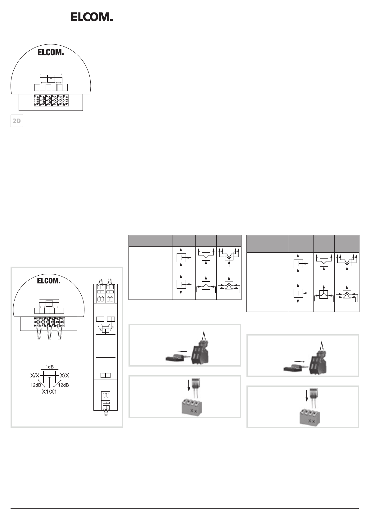
Geräteaufbau (Bilder 1, 2 und 3)
Funktion
Video-Verteiler werden zur Abzweigung, Verteilung oder zur Einkopplung der Video-Busleitung
verwendet.
Safety instructions
z
Electrical equipment may only be installed and
assembled by qualied electricians.
Failure to comply with these instructions may
result in damage to the device, re or other
hazards.
When installing and laying cables, always comply with the applicable regulations and standards for SELV electrical circuits.
These instructions are an integral component
of the product and must be retained by the end
user.
Design and layout of the device (Figures 1, 2 and 3)
Function
Video distributors are used for branching, distribution or coupling of the video bus cable.
RED61..Y, RED62..Y
Verteiler UP/REG 2Draht
Distributor ush-mounted/RMD
2-wire
1
RED621Y
Verteiler / Abzweiger
1dB
12dB12dB
X X X X
X1X1
(2)
(1) (2)
(4)
X X X X
12dB
ELCOM.
RED611Y
Verteiler / Abzweiger
1dB
X1 X1
(4)
12dB
Anschluss
Verteiler/Abzweiger
(1)(3) Anschlussklemmen X1/X1
- Abzweigung von der 2Draht Stammleitung
(2)(4) Anschlussklemmen X/X
- durchgeschleifte 2Draht Stammleitung
Verteiler 2- und 4fach
(1)(3) Anschlussklemmen X1/X1
- Eingang bei Verwendung als Verteiler
- Ausgang bei Verwendung als Einkoppler
(2)(4) Anschlussklemmen X/X
- Ausgang bei Verwendung als Verteiler
- Eingang bei Verwendung als Einkoppler
Verwendung
Verteiler/
Abzweiger
Verteiler
2fach
Verteiler
4fach
Verteilung (Abzweig)
Verzweigung des
Strangs
Einkopplung
Von Türstationen,
Etagen-, Flur- (Laubengang) und Wohnungs-Türstationen
Terminator (Abschlusswiderstand)
Nicht belegte Anschlüsse (X/X) sind durch Aufstecken eines Terminators abzuschließen.
1. Drücken
2. Einstecken
Bild 4: REG Anschlussklemmen
Einstecken
Connection
Distributor/branch
(1)(3) Connecting terminals X1/X1
- Branching of the 2-wire trunk cable
(2)(4) Connecting terminals X/X
- Looped 2-wire trunk cable
Distributor 2- and 4gang
(1)(3) Connecting terminals X1/X1
- Input when used as a distributor
- Output when used as a coupling
(2)(4) Connecting terminals X/X
- Input when used as a distributor
- Output when used as a coupling
Use
Distributor/
branch
Distributor
2gang
Distributor
4gang
Distribution (branch)
Branching of line
Coupling
From door stations,
oor door stations,
hallway (pergola) door
stations and apartment door stations
Terminator (terminating resistor)
Terminate unassigned connections (X/X) by attaching a terminator.
1. Press
2. Plug in
Figure 4: RMD connecting terminals
Plug in
(3)
Bild 5: UP Anschlussklemmen
Figure 5: Flush-mounted connecting terminals
Elcom Kommunikation GmbH - Gottfried-Leibniz-Str.1 - D-74172 Neckarsulm - www.elcom.de - 6LE000764A - 08/2015
Page 2
2
ELCOM.
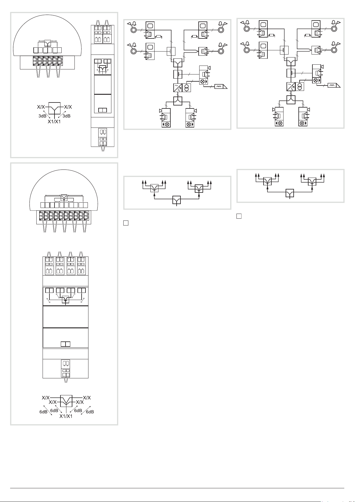
RED622Y
2-fach Verteiler
3dB3dB
X X X X
X1X1
(2) (1) (2)
(4)
(4)
X X X X
3dB
ELCOM.
RED612Y
2-fach Verteiler
X1 X1
3dB
2
2
2
2
2
2
2
2
2
2 2
2
2
4
2
2
2
2
2
2
2
2
2
2
2 2
ze
2
2
4
2
4
Bild 6: Verteilung und Einkopplung mit Verteilern
Für mehr als 4 Aus- oder Eingänge werden Video-Verteiler kaskadiert. Die Ausgänge der ersten
(3)
Video-Verteiler werden mit den Eingängen der
weiteren Video-Verteiler verbunden (Bild 7). Die
3
ELCOM.
RED624Y
4-fach Verteiler
X XX X X XX X
6dB6dB
6dB 6dB
X1X1
Dämpfungen der Video-Verteiler addieren sich
hierbei.
4fach 4fach
2fach
Bild 7: 2Draht – Verteiler, kaskadiert
Dämpfungsberechnung und Schleifenwider-
standsmessung siehe Bedienungsanleitung
(2) (2) (1) (2) (2)
Bus Strangversorgung.
4
Figure 6: Distribution and coupling with distributors
Video distributors are cascaded for more than 4
inputs or outputs. The outputs of the rst video
distributors are connected to the inputs of the additional video distributors (Figure 7). The attenuations of the video distributors are added together.
Figure 7: 2-wire distributor, cascaded
For attenuation calculation and loop resistance
measurement see bus line power supply operating instructions.
4
4gang 4gang
2gang
4
Technical data
(4)
(4)
X X X X X X X X
6dB
(4)
6dB 6dB
ELCOM.
RED614Y
4-fach Verteiler
X1 X1
(3)
(4)
6dB
Technische Daten
Betriebsspannung 24 V=
Schutzart IP20
Relative Feuchte 0 ... 65 % (keine Betauung)
Betriebstemperatur -5 … +45 °C
Lager-/Transporttemperatur -20 … +60 °C
Anschlussklemmen Steckklemmen
Maximaler Leiterdurchmesser 0,8 mm
Verteiler/Abzweiger RED611Y, RED621Y
Durchgangsdämpfung 1 dB
Abzweigdämpfung 12 dB
Abmessungen B x H x T
UP Gerät 51 x 42 x 16 mm
REG Gerät 17,5 x 94 x 58 mm, 1 TE
Verteiler 2fach RED612Y, RED622Y
Verteilerdämpfung 3 dB
UP Gerät 51 x 42 x 16 mm
REG Gerät 17,5 x 94 x 58 mm, 1 TE
Verteiler 4fach RED614Y, RED624Y
Verteilerdämpfung 6 dB
UP Gerät 51 x 42 x 16 mm
REG Gerät 35 x 94 x 58 mm, 2 TE
Gewährleistung
Technische und formale Änderungen am Produkt,
soweit sie dem technischen Fortschritt dienen,
behalten wir uns vor.
Wir leisten Gewähr im Rahmen der gesetzlichen
Bestimmungen.
Im Servicefall bitte an den Anlagenerrichter wenden.
Operating voltage 24 V=
Degree of protection IP 20
Relative humidity 0 ... 65 % (no condensation)
Operating temperature -5 … +45 °C
Storage/transport temperature -20 … +60 °C
Connecting terminals plug-in terminals
Maximum conductor diameter 0.8 mm
Distributor//branch RED611Y, RED621Y
Transmission loss 1 dB
Branch attenuation 12 dB
Dimensions W x H x D
Flush-mounted device 51 x 42 x 16 mm
RMD device 17.5 x 94 x 58 mm, 1 module
Distributor 2gang RED612Y, RED622Y
Distributor attenuation 3 dB
Flush-mounted device 51 x 42 x 16 mm
RMD device 17.5 x 94 x 58 mm, 1 module
Distributor 4gang RED614Y, RED624Y
Distributor attenuation 6 dB
Flush-mounted device 51 x 42 x 16 mm
RMD device 35 x 94 x 58 mm, 2 modules
Warranty
We reserve the right to realise technical and formal
changes to the product in the interest of technical
progress.
Our products are under guarantee within the scope
of the statutory provisions.
In case of service issues, please contact your systems‘ engineer.
6LE000764A - 08/2015Elcom Kommunikation GmbH - Gottfried-Leibniz-Str.1 - D-74172 Neckarsulm - www.elcom.de -
 Loading...