


Elcold Frysere Hobro ApS
Løgstørvej 81 Hørby 9500 Hobro Denmark
Phone +45 9657 2222 Fax +45 9852 4685
Email elcold@elcold.com www.elcold.com
i.c. graphics cph

User Instructions
Pro* Frost
Low Temperature Freezers Model PRO/XLT

SAFETY INFORMATIONS
The PRO/XLT freezers contains environmentally friendly but flammable refigerants. It means
danger of explosion if for any reason the refigerants are allowed to escape from the system.
The refigeration system must never be accessed by unauthorized personal.
When transporting and installing the unit, ensure that no part of the tubing system is damaged.
If the tubing is damaged and leak occurs, avoid any ignition sources and naked flames near
the unit, and ventilate the room immediately.
In order to avoid formation of flammable gas/air mixtures an case of a leak from the refigera
tion system, the room where the unit is placed must have a volume of minimum 40 m3 cor
-
responding to a surface area of approx. 4 m2 in a room with normal ceiling height.
WARNING!!!
The ventilation openings must never be covered or blocked.
Never use a stream or water cleaning device during cleaning or defrosting in order to avoid
short circuits in the electrical system.
Do not place any electrical devices in the freezer.
Products containing flammable gasses and explosives must not be stored in the freezer.
-
User Instructions Low Temperature Freezers Model PRO/XLT
2

USER INSTRUCTIONS
Congratulations on your new low temperature freezer. We trust that it will serve you
for many years to come. In order to gain
optimum benefit from your freezer, please
read the following instructions thoroughly
and act accordingly. The low-temperature
freezers are used for freezing and long-term
storing of food products, medical preparations ( vaccines, blood plasm, ect.) and
other biological products.
1. Environmental protection and disposal.
The packaging is designed to protect the
appliance and its components during
transportation, and it is made of recyclable
materials.
• Please return the packaging to an
official collection point for recycling.
• Old appliances contain reusable
materials and should not be disposed
of together with household refuse.
• Remove the spring-action hinges from
the appliance, in order to prevent
children from being entrapped in the
appliance.
• Ensure that no part of the refrigeration
tubing is damaged as the refrigerant
in the appliance risks escaping to the
environment.
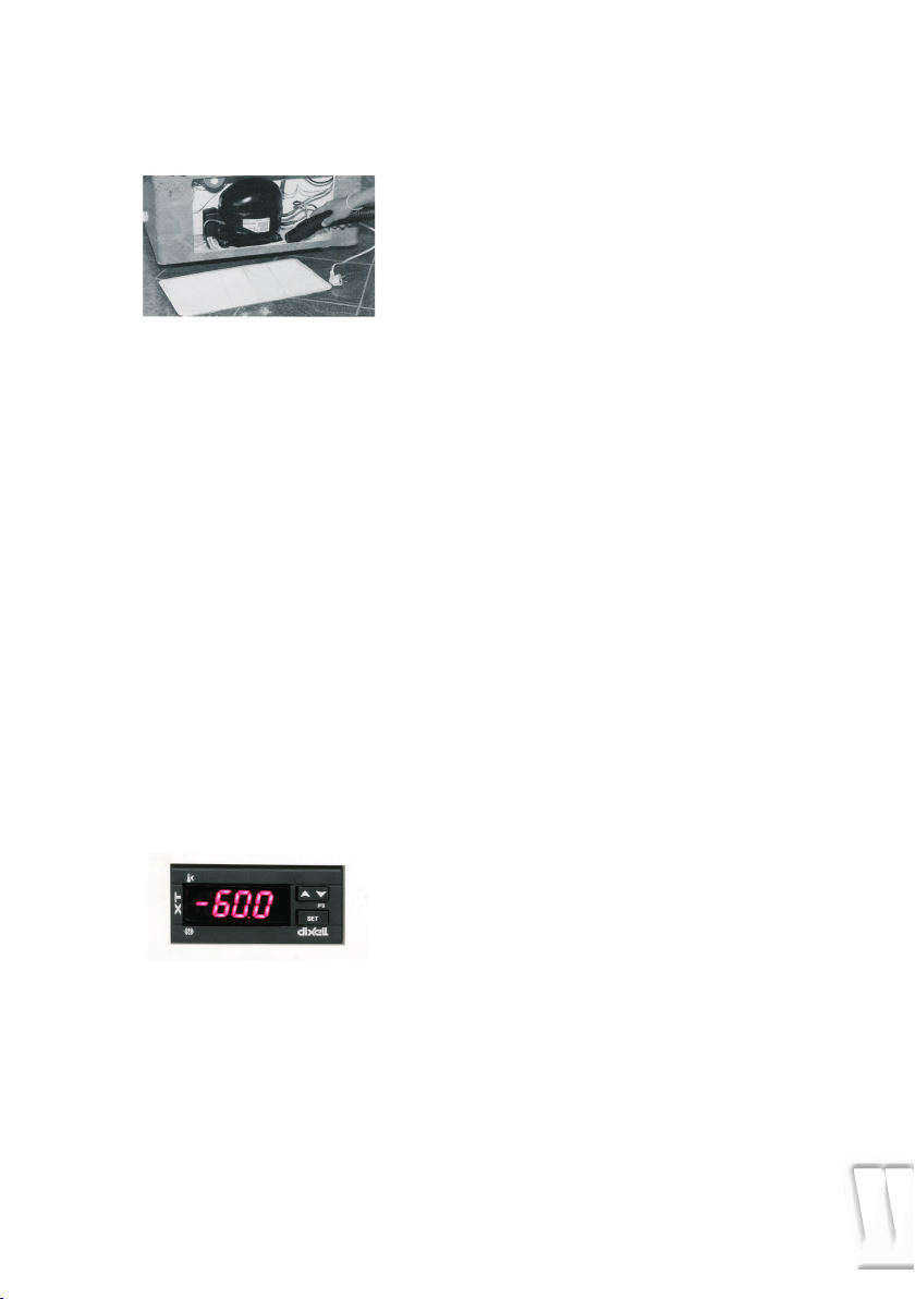
• Information about refrigerant type
and amount will be found on the type
plate on the rear of the appliance
(Fig. 1).
2. Safety instructions.
• In order to prevent injuries and or
damage to the appliance, it should
be unpacked and set up by min. two
people.
• If upon unpacking the appliance is
found damaged, do not connect to
the mains, but contact the supplier.
•
Interference with or repair to the
appliance should only be carried out
by authorized personnel, in order to
avoid any injuries. (contact the sup plier for further information).
• Never put naked flames or other igni tion sources inside the appliance.
• Never touch the freezers interior or
GB
products in the freezer when the
freezer is operating. Use gloves or alike
in order to avoid injuries (frost-bite).
• Keep the key to the appliance away
from the appliance and out of the
reach of children.
3. IMPORTANT NOTE !!!
• The type of refrigerant in the –60°C
freezers, is a mixture of different
flammable hydrocarbons.
These freezers are designed and
tested according to the EN 378 stan dard, under clause A3 room and L3
refrigerants, this means that the
volume of the room where the freezers
is placed must have a volume of mini mum 40m
4m
height.
4. Connection to the mains.
• For safety reasons the appliance must
be earthed. If you are in any doubt,
please contact an authorized electri
cian.
• The appliance should be left for 5
hours before it is connected to the
mains. If the appliance is connected
before that, there is a risk of damaging
the compressor.
• If for any reason the appliance is
disconnected from the mains, please
wait 10 minutes before re-connecting.
The electronic starting device needs
this time to cool down, before a safe
re-start can be made.
5. Before use.
• Before use, the interior of the appli ance should be cleaned with a mild
soap solution, and wiped off with a dry
clean cloth. Never use any kind of
solvent or other chemicals.
3
corresponding to approx.
2
in a room with a normal floor
User Instructions Low Temperature Freezers Model PRO/XLT
3

6. Setting up the freezer.
The freezer should not be placed where it
might be splashed with water, in extreme
high humidity or in direct sunlight. Any of
these factors may lead to a reduction in
performance and shorten the life span of
the components. The freezer should be
placed on a horizontal level, and should
not be placed close to a heating appliance
or heating tubes. Allow a minimum of 50mm
(2”) clearance on the side and the back.
The side with the ventilation grill should have
a clearance of at least 100 mm (4”) in order
to allow the heat from the compressor
motor to dissipate. Underneath the appli
ance there should be a gap of 15 mm ap
-
prox. (1⁄2”). On a soft surface, e.g. carpet,
it may be necessary to ensure the correct
distance by means of spacers.
7. Electrical supply.
The electrical supply should always be in
accordance with the rating plate on the
back of the freezer.
The supply must always be in accordance
with the law and regulations regarding
electrical safety, if any doubts contact your
supplier.
there is an electricity supply to the plug or if
the fuse is blown. If not please go to trouble
shooting page 6. 18.
9.Operating the freezer
The empty freezer should be switched on
for at least 5-6 hours prior to loading of the
freezer. The freezer should not be loaded
above the inside walls which is also the load
line limit.
Please note: After the lid has been opened,
there will be a vacuum created inside the
freezer due to the low temperatures. Wait a
few minutes before trying to reopen the lid
otherwise the handle could be damaged.
10.Defrosting.
In order for the freezer to work to its maxi
mum efficiency the cabinet should be de
-
frosted when a approx. 2mm thick ice layer
has formed inside the cabinet.
The ice layer is easily removed with a plastic
or wooden scraper.
Never use a sharp metal
object which might will cause damage to
the inner liner.
The defrosting frequency is determined
mainly by two factors the usage pattern
(number of lid openings) and the relative
humidity. Excess water can be drained out
by using the drain water outlet on the front
of the freezer.
Fig. 1
8. Starting Up.
In case the compressor does not start when
the freezer has been plugged in, the electri
cal supply may not be in order. Check if
User Instructions Low Temperature Freezers Model PRO/XLT
11.Cleaning.
Cleaning should be done when needed.
When used in a dirty environment it might
be necessary to remove the compressor
compartment grill, and clean the compres
sor compartment eventually with a vacuum
cleaner.
If the cleaning process is neglected there
is a risk that the performance of the freezer
will be effected, and even damage to the
4
-
compressor could occur due to overheating.
12. Storage.
If the freezer is stored for a period of time,
the lid should be kept open for free circula
tion of air inside the cabinet in order to
avoid corrosion of the inner liner.
13. Temperature control PRO/XLT- freezers.
The temperature inside the freezer is con
trolled by the electronic controller in the
front grill. The controller has a digital readout
of the temperature inside the cabinet. and
the option of changing the temperature
inside the cabinet.
14. External voltage and temperature alarm.
Optionally the freezer can be equipped with
a battery operated alarm box with connections for external alarm for voltage failure
and temperature alarm. The battery should
be exchanged every two years.
Please note! When commissioning the
freezer, the battery must be turned into its
correct position.
15.Dixell controller.
16. Functions.
How to see the set point:
1.Press and immediately release the SET key,
the display will now show the set point value.
2.Press and immediately release the SET key
or wait for 5 seconds to display the probe
value again.
How to lock and unlock the keyboard
1.Press the up and down keys simultaneously
for more than 3.seconds.
How to change the set point
1.Press the SET key for more than 3.seconds
to change the set point value.
2.The set point value will be displayed and
the LED starts flashing.
3.To change the set point value, push the up
or down arrow.
4. To memorise the new setting press the SET
key again or wait 15 seconds for the controller to return to normal display of the probe
temperature.
17. Setting the controllers offset value
The LAB/ULT freezer is designed for long time
and safe storage of sensitive products.
In some situations the PRO/XLT freezer is also
used for other applications like in laboratories for different low temperature test.
Depending on the actual situation it might
be necessary to change the controllers off
set value in order to get a correspondence
between the reading on the display and the
actual temperature inside the cabinet.
The factory setting is an offset of 2 dgr.C.
The offset can be adjusted in the following
way.
Unlock the keyboard.
Enter the programming mode by pressing
the SET and arrow down keys for 3 seconds.
Select the parameter “Opb” by pressing
arrow up or down key.
Press the SET key to display its value.
Use arrow up or down to change its value.
The offset can be adjusted to +/- 12 dgr .C
Press SET to store the new value.
Press SET + arrow up or wait 15 seconds
without pressing any key. The new value will
now be stored.
For more detailed information about
programming the Dixell controllers please
consult the attached manuals.
User Instructions Low Temperature Freezers Model PRO/XLT
5

18. Trouble shooting.
The appliance is not operating. Please
check:
Is the electrical plug connected to the
mains (wall socket)? Has the fuse blown?
The temperature inside the appliance is too
high. Please check:
Is the Dixell controller set to the correct
temperature?
Has an excess amount of ice formed inside
the appliance?
The appliance is operating continuously.
Please check:
Is the ambient temperature to high?
Has the appliance recently been loaded
with a large amount of warm products?
If you have checked the above points
and the appliance is still not working as
expected, please contact your local dealer
for further advice.
19. LN 2 or LCO 2 back-up
On the rear side of the cabinet there is a
label and a marking, where it is possible to
insert either a temperature probe or a backup LN2 or LCO2 supply.
The inner and outer skins are pre-drilled.
IMPORTANT NOTE !!!
Do not attempt to drill or in other way make
access to the freezers interior other places
than at the marking, there is a risk of
damaging the freezers tubing system,
resulting in a leakage with inflammable
gasses.
Back-up inlet
User Instructions Low Temperature Freezers Model PRO/XLT
6

DIXELL XT111C FOR PRO/XLT MODELS
XT111C
Single Stage Digital Controller
For Temperature
GENERAL WARNING
Please read before using this
manual
• This manual is part of the product and
should be kept near the instrument for
easy and quick reference.
• The instrument shall not be used for
purposes different from those de
scribed hereunder. It cannot be used
as a safety device.
• Check the application limits before
proceeding.
Safety Precautions
• Check the supply voltage is correct
before connecting the instrument.
• Do not expose to water or moisture:
use the controller only within the
operating limits avoiding sudden
temperature changes with high at-
mospheric humidity to prevent forma tion of condensation
• Warning: disconnect all electrical con nections before any kind of mainte nance
• The instrument must not be opened.
• In case of failure or faulty operation
send the instrument back to the dis tributor with a detailed description of
the fault.
• Consider the maximum current which
can be applied to each relay (see
Technical Data).
• Ensure that the wires for probes, loads
and the power supply are separated
and far enough from each other,
without crossing or intertwining.
• In case of applications in industrial
environments, the use of mains filters
(our mod. FT1) in parallel with
inductive loads could be useful.
GENERAL DESCRIPTION
The XT110C and XT111C are single-stage
ON/OFF controllers for temperature,
humidity and pressure applications with
direct or inverse action, user-selectable.
The analogue input type can be set by
parameter between the following,
according to the model:
- PTC, NTC;
- PTC, NTC, Pt100, Thermocouple J, K, S;
- 4÷20mA, 0÷1V, 0÷10V.
FIRST INSTALLATION
Probe setting
The pre-set probe
type is written on the
label of the
instrument, see
picture. If it is
different from theprobe that has be used,
set the probe following procedure below
How to set the probe.
1. Enter the programming menu by
pressing the SET+ n for 3s.
2. Select the Pbc (Probe configuration)
parameter and push the SET key.
3. Set the kind of probe:
a. Controller for temperature: Pt=
Pt100, J = J thermocouple, c = K
thermocouple,
S = S thermocouple;
Ptc = PTC; ntc = ntc
b. Controller with current or
voltage inputs: cur=4÷20mA, 0-
1= 0÷1V, 10= 0÷10V
4. Push the SET key to confirm it.
5. Switch the controller
off and on again
NOTE: Before proceeding check and, if
necessary; set with appropriate values the
Minimum Set Points (LS1 e LS2) and
Maximum Set Points (US1 e US2). See
also the paragraphs concerning the
programming.
User Instructions Low Temperature Freezers Model PRO/XLT
7

Front panel commands
SET:
To display and modify target set point; in
programming mode it selects a parameter
or confirm an operation.
TO SWITCH THE INSTRUMENT ON/OFF: If the
function is enabled (par. onF=yES), by press
ing the SET key for more than 4s the control
ler is switched OFF. To switch the instrument
on again press the SET key.
o UP:
in programming mode it browses the param
eter codes or increases the displayed value.
Hold it pressed for a faster change
n DOWN:
in programming mode it browses the pa
rameter codes or decreases the displayed
value. Hold it pressed for a faster change
KEY COMBINATIONS:
o + n To lock & unlock the keyboard.
SET + n To enter in programming mode.
SET + o To return to the room temperature
display.
Use of LEDS
A series of light points on the front panels
is used to monitor the loads controlled by
the instrument. Each LED function is
described in the following table.
LED
MOD
FUNCTION
E
Output relay enabled
ON
LED
LED
E.S.
1
2
- Programming Phase (flashing
flashing
with LED2)
flash-
- Programming Phase (flashing
ing
with LED1)
Energy saving activated by
ON
digital input
ON
- ALARM signal
- In “Pr2” indicates the
parameter is also present in
“Pr1”
TO see THE SETPOINT
SET
1. Push and release the
key to see the Set point
value;
2. To come back to the normal
display push again the
or wait 10s.
TO CHANGE THE SETPOINT
SET
1. Hold pushed the SET key
for 3s to change the Set
point value;
2. The value of the set point will
be displayed and the LED1 & 2
start blinking;
3. To change the Set value push
the o or n arrows within 10s.
4. To memorise the new set point
-
value push the
SET key again or
wait 10 s.
TO enter the parameters list “Pr1”
To enter the parameter list “Pr1” (user
accessible parameters) operate as follows:
1. Push for 3s the
SET + n keys
(LED1 & 2 start blinking).
2. The controller will display the
SET
first parameter present in the
Pr1 menu..
TO ENTER the parameters list “Pr2”
The “Pr2” parameter list contains the
configuration parameters. A security code
is required to enter it.
1. Enter the “
Pr1” level, see above
paragraph.
2. Select “
press the “
3. The “
Pr2” parameter and
SET” key.
PAS” flashing message is
displayed, shortly followed by
“
0 - -” with a flashing zero.
4. Use o or n to input the security
code in the flashing digit; con
firm the figure by pressing “
The security code is “321”.
5. If the security code is correct
the access to “Pr2” is enabled
by pressing “
SET” on the last
digit.
SET
SET key
SET”.
User Instructions Low Temperature Freezers Model PRO/XLT
8

Another possibility is the following:
After switching ON the instrument, within 30
seconds, push SET + n keys together for 3s:
the Pr2 menu will be entered.
HOW TO MOVE A PARAMETER FROM THE
“PR2” MENU TO “PR1” AND VICEVERSA.
Each parameter present in “
can be removed or put into “
level, by pressing “
SET + n”.
Pr2” MENU
Pr1”, user
In “Pr2” when a parameter is present in
“Pr1” the LED is on.
HOW TO CHANGE a parameter
To change a parameter value operates as
follows:
1. Enter the Programming mode
2. Select the required parameter.
3. Press the “
SET” key to display its value.
4. Use “UP” or “DOWN” to change its value.
5. Press “
SET” to store the new value and
move to the following parameter.
TO EXIT: Press SET + UP or wait 15s
without pressing a key.
NOTE: the set value is stored even when the
procedure is exited by waiting the timeout
to expire.
HOW TO LOCK THE KEYBOARD
1. Keep pressed for more than 3 s the the
o and n keys.
2. The “POF” message will be displayed
and the keyboard will be locked. At this
point it will be possible only to see the
set point or the MAX o Min temperature
stored
3. If a key is pressed more than 3s the
“POF” message will be displayed.
TO UNLOCK THE KEYBOARD
Keep pressed together for more than 3s
the the o and n keys, till the “Pon” message
will be displayed.
ON/OFF function
TO SWITCH THE INSTRUMENT ON/OFF:
If the function is enabled (par. onF=yES),
by pressing the SET key for more than 4s
the controller is switched OFF. To switch the
instrument on again press the SET key.
PROBES AND MEASURING RANGE
Pro Down Scale Full Scale
be
NTC -40˚C/-40˚F
PTC
-50˚C/-58˚F
Pt10
-200˚C/-328˚F
0
TcK
0˚C/32˚F
TcJ
0˚C/32˚F
TcS
0˚C/32˚F
110˚C/230˚F
150˚C/302˚F
600˚C/1112˚F
1300˚C/1999˚F
600˚C/1112˚F
1400˚C/1999˚F
List of Parameters
REGULATION
Hy1
Differential: (-Full Sc. / Full Sc.) Intervention
differential for set point. It can be set with
positive value or with negative value.
The kind of action (direct or inverse) de
pends on the S1C
parameter (in or di).
LS1
Minimum set point: (Down Sc.÷ Set) Sets the
minimum acceptable value for the set point.
US1 Maximum set point: (Set÷ Full Sc.) Sets
the maximum acceptable value for set
point.
S1C
Action type: S1C=in inverse action (heat-
ing/ humidifying/increase pressure);
direct action (cooling /dehumidifying/de
S1C=dir
-
crease pressure).
AC
Anti-short cycle delay: (0÷250 sec) Minimum
time between the switching off and the fol
-
lowing switching on
on
Minimum time a stage stays switched ON
(0÷250 sec)
ono:
Minimum time between 2 following switching
ON of the same load (0÷120 min).
User Instructions Low Temperature Freezers Model PRO/XLT
9

ALARMS
ALC
Temperature alarms configuration:
it determines if alarms are relative to set point or
referred to absolute values.
rE relative to set point; Ab absolute temperature
ALL
Minimum alarm:
with ALC=rE: relative to set point, (0÷|Down
Sc.-Set|) this value is subtracted from the set
point. The alarm signal is
enabled when the probe values goes below
the “SET-ALL” value.
with ALC=Ab absolute value, minimum
alarm is enabled when the probe values
goes below the “ALL” value.
ALU
Maximum alarm:
with ALC=rE: alarm relative to set point,
(0÷|Full Sc.-Set|) Maximum alarm is en
abled when the probe values exceeds the
“SET+ALU” value.
with ALC=Ab: absolute alarm, (Set÷Full Sc.)
Maximum alarm is enabled when the probe
values exceeds the “ALU” value.
ALH
Differential for alarm recovery: (0,1÷Full
scale) the alarm recovers when probe value
is higher than Alarm value + ALH.
ALd
Alarm delay:(0÷999 min) time interval be-
tween the detection of an alarm condition
and alarm signalling.
dAO
Delay of alarm at start-up: (0÷23.5h) time
interval between the detection of the alarm
condition after instrument power on and
alarm signalling.
So1
Relay status with faulty probe: So1
=oFF open;
So1=on closed.
tbA
Status of alarm relay after pushing a key.
(XT111C only):
oFF = relay disabled; on = relay enabled.
AS
Alarm relay configuration (XT111C only):
cL = 4-6 terminals open with alarm; oP = 4-6
terminals closed with alarm.
PROBES AND DISPLAY
LCI
Start of scale, only with current or voltage
input: (-1999÷1999) Adjustment of read out
corresponding to 4mA or 0V input signal.
UCI
End of scale, only with current or voltage
input: (-1999÷1999) Adjustment of read out
corresponding to 20mA
or 1V or 10V input signal.
oPb
Probe calibration: (-999÷999) allows to adjust
possible offset of the probe.
rES
Decimal point ON/OFF: (rES=in OFF; rES=dE
ON; rES= cE with 2 decimal points, only for
current or voltage input) select
the resolution of the controller.
NOTE: the decimal point selection is not
available on models with thermocouple
input.
UdM
Measurement unit: it depends on models:
for temperature:°C = Celsius; °F = Fahrenheit.
with 4÷20mA, 0÷1V, 0÷10V input : 0= °C;
1= °F, 2= %RH, 3=bar, 4=PSI, 5=no measure-
ment unit.
PbC
Probe selection: it sets the kind of probe. It
depends on models
for temperature NTC/PTC: Ptc = PTC; ntc =
ntc.
for temperature standard: Pt= Pt100, J = J
thermocouple,
c = K thermocouple, S = S
thermocouple; Ptc = PTC; ntc = ntc.
with 4÷20mA, 0÷1V, 0÷10V input:
cur=4÷20mA, 0-1= 0÷1V, 10= 0÷10V.
P3F
Third wire presence for Pt100 probe: for using
2 or 3 wires Pt100 probes: no = 2 wires probe;
yES = 3 wires probe.
User Instructions Low Temperature Freezers Model PRO/XLT
10

DIGITAL INPUT
HES
Set point change during during the Energy
Saving cycle: (Down Sc./Full Sc.) sets the
variation of the set point during the Energy
Saving cycle.
i1F
Digital input operating mode:
configure the digital input function:
c-H
= to invert the kind of action: direct -
reverse;
oFF = to switch the controller off.; AUS = Not
used; HES = Energy Saving;
EAL = generic external alarm; bAL = serious
external alarm: it switches off the loads.
i1P
Digital input polarity:
CL: the digital input is activated by
closing the contact;
OP: the digital input is activated by
opening the contact
did
Digital input alarm delay: (0÷255 min) delay
between the detection of the external
alarm condition (i1F= EAL or i1F = bAL) and
its signalling.
OTHER
Adr
RS485 serial address (0÷247) identifies the
instrument within a control or supervising
system.
onF
Swithching ON/OFF enabling from keyboard:
(no = disabled; yES=enabled) It permits the
switching ON/OFF of the instrument by press
ing the SET key for more than 4s.
Ptb
Parameters table: (read only) Shows the
code of the parameters map.
rEL
Software release: (read only)
Pr2
To access the Pr2 parameter programming
menu.
Installation and mounting
Instrument XT110C and XT111C shall be
mounted on vertical panel, in a 29x71 mm
hole, and fixed using the special brackets
supplied.
PANEL
BRACKET
(PUSH TO RELEASE)
To obtain an IP65 protection grade use the
front panel rubber gasket (mod. RG-C) as
shown in figure.
The temperature range allowed for correct
operation is 0÷60 °C. Avoid places subject
to strong vibrations, corrosive gases, exces
sive dirt or humidity. The same recommen
dations apply to probes. Let air circulate by
the cooling holes.
Electrical connections
The instruments are provided with screw
terminal block to connect cables with a
cross section up to 2,5 mm². Before con
necting cables make sure the power supply
complies with the instrument’s requirements.
Separate the input connection cables from
the power supply cables, from the outputs
and the power connections. Do not exceed
the maximum current allowed on each
relay, in case of heavier loads use a suitable
external relay.
Serial connections
All models can be connected to the
monitoring and supervising system XJ500
using the serial port. The external XJ485
serial module to interface the instrument
with the monitoring and supervising system
XJ500 is required.
The standard ModBus RTU protocol it is
used.
NOTE: Instruments with current or voltage
input and 230V or 115V supply, cannot be
connected to the XJ485 serial module.
-
-
-
User Instructions Low Temperature Freezers Model PRO/XLT
11

How to use the HOT KEY
How to program a hot key from the
instrument (UPLOAD)
1. Program one controller with the front
keypad.
2. When the controller is ON, insert the
“Hot key” and push o key; the “uPL”
message appears followed a by
flashing “
End”
3. Push “SET” key and the End will stop
flashing.
4. Turn OFF the instrument remove the
“Hot Key”, then turn it ON again.
NOTE: the “Err” message is displayed for
failed programming. In this case push
again o key if you want to restart the
upload again or remove the “Hot key”
to abort the operation.
HOW TO PROGRAM AN INSTRUMENT USING A
HOT KEY (DOWNLOAD)
1. Turn OFF the instrument.
2. Insert a programmed “Hot Key” into the
5 PIN receptacle and then turn the Con troller ON.
3. Automatically the parameter list of the
“Hot Key” is downloaded into the
Controller memory, the “
is blinking followed a by flashing “
doL” message
End”.
4. After 10 seconds the instrument will restart
working with the new parameters.
5. Remove the “Hot Key”..
NOTE: the message “Err” is displayed for
failed programming. In this case turn the
unit off and then on if you want to restart
the download again or remove the “
Hot
key” to abort the operation.
digital input
XT110C and XT111C have 1 free contact
digital input. It is programmable in 5
different configurations by the “
i1F”
parameter.
invert the kind of action: heatingcooling
(I1F = C-H)
This function allows to invert the regulation
of the controller: from direct to inverse and
viceversa.
REMOTE ON/OFF (I1F = OFF)
This function allows to switch ON and OFF
the instrument.
GENERIC ALARM (i1F = EaL)
As soon as the digital input is activated the
unit will wait for “did” time delay before
signalling the “EAL” alarm message. The
outputs status don’t change. The alarm
stops just after the digital input is deactivated.
serious alarm mode (I1F = BAL)
When the digital input is activated, the unit
will wait for “did” delay before signalling the
“bAL” alarm message. The relay outputs are
switched OFF. The alarm will stop as soon as
the digital input is de-activated.
energy saving (I1F = HES)
The Energy Saving function allows to change
the set point1 value as the result of the SET1
+ HES (parameter) sum. This function is enabled until the digital input is activated.
ALARM SIGNALS
Mess-
Cause Outputs
age
“PFo”
“PFc”
“HA”
“LA”
“EAL”
“bAL”
Probe broken
or absence
Probe short
circuited
Maximum
alarm
Minimum
alarm
External alarm
Alarm output ON;
Output according
to Parameter “So1”
Alarm output ON;
Output according
to Parameter “So1”
Alarm output ON;
Other outputs
unchanged
Alarm output ON;
Other outputs
unchanged
Output unchanged
Output OFFSerious
external alarm
alarm relay status (XT111c)
Status of the
AS = CL AS = oP
instrument
Instrument off
Normal operating
Alarm present
4-6 closed
4-6 closed
4-6 closed
4-6 open
4-6 open 4-6 closed
Silencing buzzer / alarm relay output
Once the alarm signal is detected the buzzer, if present, can be disabled by pressing
any key.
User Instructions Low Temperature Freezers Model PRO/XLT
12
XT111C: the alarm relay status depends on the tbA parameter: with tbA=yES the relay is disabled by pressing any key, with tbA=no the alarm relay remains enabled as long as the alarm
lasts. The display signal remains as long as the alarm condition remains.
Alarm recovery: Probe alarms “PFo”, “PFc” start few seconds after the fault in the probe; they
automatically stop few seconds after the probe restarts normal operation. Check connections
before replacing the probe. Max. and min. alarms “
as the variable returns to normal values. Alarms “
HA” and “LA” automatically stop as soon
bAL” and “EAL” recover as soon as the digital
input is disabled.
Technical data
Housing: self extinguishing ABS.
Case: frontal 32x74 mm; depth 60mm;
Mounting: panel mounting in a 71x29 mm panel cut-out.
Protection: IP20.
Frontal protection: IP65 with frontal gasket RG-C (optional).
Connections: Screw terminal block £ 2,5 mm² heat-resistant wiring.
Power supply: 12Vac/dc, ±10% or: 24Vac/dc ± 10% or 230Vac ± 10%, 50/60Hz
or 110Vac, ± 10%, 50/60Hz
Power absorption: 3VA max.
Display: 3 1⁄2 digits, red LED
Inputs: according to the order: NTC/PTC or NTC/PTC /Pt100/Thermo
couple J, K, S or 4÷20mA/ 0÷1V / 0÷10V
Relay outputs: Load relay SPDT 8(3)A, 250Vac
Alarm: (XT111C) relay SPDT 8(3)A, 250Vac
Other output: buzzer (optional)
Kind of action: 1B; Pollution grade: normal, Software class: A.
Data storing: on the non-volatile memory (EEPROM).
Operating temperature: 0÷60 °C (32÷140°F).
Storage temperature: -30÷85 °C (-22÷185°F).
Relative humidity: 20÷85% (no condensing)
Measuring and regulation range: according to the probe
Controller Accuracy a 25°C: better than ±0,5% of full scale
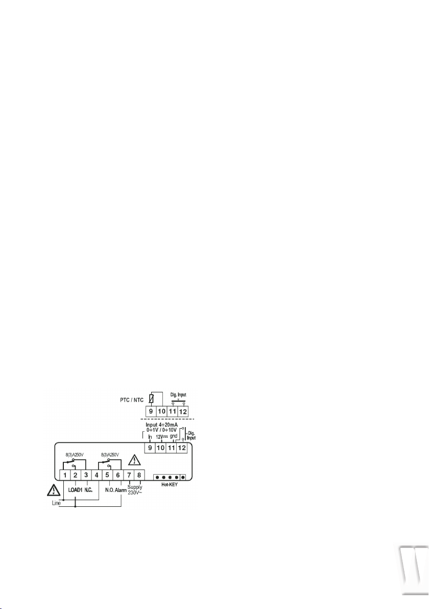
CONNECTIONS
XT111C - 230V AC OR 115V AC
Probe: Pt100 = 91-11 (10); Thermocouple
J, K, S = 9(+) -11 (-)
115Vac Supply: 7-8
User Instructions Low Temperature Freezers Model PRO/XLT
13

DEFAULT SETTING VALUES
Set
Hy1
LS1
US1
S1C
Ac
on
ono
Set point
Differential
Minimum set point
Maximum setpoint
Action type output
Anti-short cycle delay
Minimum time a stage stays switched ON
Minimum time between 2 following switching
ON of the same load
ALC
ALL
ALU
ALH
ALd
dAO
So1
tba¹
AS¹
Lci²
Uci²
OPb
rES
UdM
PbC
P3F
HES
i1F
i1P
did
Adr
OnF
Ptb
rEL
Pr2
Alarm configuration
Minimum alarm (ALC=rE)
(ALC=Ab)
Maximum alarm (ALC=rE)
(ALC=Ab)
Alarm recovery differential
Alarm delay
Alarm delay at start up
Output status with faulty pr.
Alarm relay disabling
Alarm relay polarity
Start scale with current or voltage input
End scale with current or voltage input
Probe calibration
Resolution
Measurement unit
(temp.)
(current/voltage)
Kind of probe
3rd wire presence
Energy saving differential
Digital inputconfiguration
Digital input polarity
Alarm delay for dig. input
Serial adress
oFF function enabling
Parameter table
Software release
To access the Pr2
LS1+US1
-Full Sc./Full Sc.
Down Sc./Set
Set/Full Sc.
in=Inverse; dir=directed
0 -250 sec.
0 -250 sec.
0 -120 min.
rE=relat.; Ab=absolute
0 +[Start Sc.-Set].
Start Sc.+ALu
0 +[Full Sc.-Set]
ALL+Full scale
0 -Full scale
0 -999 min
0 -23h 50 min
oFF=open on=closed
no; yES
CL + oP
-1999 -1999
-1999 -1999
-Full Sc./Full Sc.
in=NO; dE=0,1; cE=0,01
°C=°C; °F;
0=°C; 1=°F; 2=HR; 3=bar;
4=PSI; 5=off
PT=Pt100; J=tcJ; c=tck;
S=tcS; Ptc=PTC; ntc=NTC;
0-1=0-1V; 10=0+10V;
cur=0-20mA
no=2 wires;
yES=3wires
Down SC./Full Sc.
c-H/oFF/AuS/HES/EAL/bAL
cL=closed; oP=open
0-120 m
0-247
no=not enabled;
yES=enabled
Readable only
Readable only
Readable only
COD Name Range °C/°F Lev
0/32
-1/-2
min
max
in
0
0
0
rE
10.0/ 20
10.0/ 20
2.0/4
15
1.3
oFF
yES
oP
various
various
0.0
in
various
various
no
0.0
EAL
cL
0
1
no
--
--
321
-
Pr1
Pr2
Pr2
Pr2
Pr2
Pr2
Pr2
Pr2
Pr2
Pr2
Pr2
Pr2
Pr2
Pr2
Pr2
Pr2
Pr1
Pr1
Pr1
Pr2
Pr1
Pr1
Pr2
Pr2
Pr2
Pr2
Pr2
Pr2
Pr2
Pr2
Pr2
Pr1
User Instructions Low Temperature Freezers Model PRO/XLT
14

Factory settings PRO/XLT models.
Ambient temperature
Net volume
Net volume
Height with 50 mm castors
Height with open lid
Width
Insulation thickness
Depth excl. handle and hinges
Power consumption at +25˚ C
Fuse
Temeprature range
Noise level
Weight
˚C
litres
cu. ft.
mm
mm
mm
mm
mm
Watts
A
˚C
dBa
kg
+15˚ to +25˚
130
4,6
920
1620
720
100
730
330
10
-30˚ to -60˚
< 51
53
+15˚ to +25˚
230
8,1
920
1620
1050
100
730
410
10
-30˚ to -60˚
< 51
68
+15˚ to +25˚
300
10,6
920
1620
1300
100
730
560
10
-30˚ to -60˚
< 51
78
PRO 11/11 XLT PRO 21/21 XLT PRO 31/31 XLT
PRO/XLT
PRO 60/60 XLTPRO 41/41 XLT
+15˚ to +25˚
360
12,8
920
1620
1500
100
730
610
10
-30˚ to -60˚
< 51
89
+15˚ to +25˚
485
17,3
920
1620
1700
80
730
610
10
-30˚ to -60˚
< 51
95
Description
Regulation
Set point
Different (Hysteresis)
Minimum set point
Maximum set point
Action type output 1
Anti-short cycle delay
Minimum time a stage stays switched on
Minimum time between 2 following
switching ON of the same load
Alarm and safety
Alarm configuration
Minimum alarm
Maximum alarm
Alarm recovery differential
Alarm delay
Alarm delay at start up
Alarm relay disabling
Alarm relay polarity
Out1 status with faulty pr.
Other
Probe calibration
Resolution
Measurement unit (temp.)
Kind of probe
3rd. wire presence
Energy saving differencial
Digital input configuration
Digital input polarity
Alarm delay for dig. input
Serial address
oFF function enabling
Label
Set
Hy1
LS1
US1
S1C
Ac
on
ono
-60
Food
-60
1,5
-60
-45
in
0
0
0
ALC
ALL
ALU
ALH
Ald
dAO
tbA
AS
So1
Opb
rES
udM
Pbc
P3F
HES
i1F
i1P
did
Adr
OnF
re
5,0
20,0
2,0
60
10,0
on
OP
OFF
5
De
C
Pt
YES
0
EAL
cL
0
1
NO
Dixell XT111C
-65
Research
-65
0,7
-65
-45
in
0
0
0
re
3,0
10,0
2,0
5
8,0
on
OP
OFF
2
De
C
Pt
YES
0
EAL
cL
0
1
NO
Technical specifications:
15
User Instructions Low Temperature Freezers Model PRO/XLT

Wiring diagrams
Censor
Power supply
230V
50/60 HZ
User Instructions Low Temperature Freezers Model PRO/XLT
Censor
Power supply
230V
50/60 HZ
16

User Instructions Low Temperature Freezers Model PRO/XLT
17
 Loading...